JP2007250967A - Plasma treating apparatus and method, and focus ring - Google Patents
Plasma treating apparatus and method, and focus ring Download PDFInfo
- Publication number
- JP2007250967A JP2007250967A JP2006074372A JP2006074372A JP2007250967A JP 2007250967 A JP2007250967 A JP 2007250967A JP 2006074372 A JP2006074372 A JP 2006074372A JP 2006074372 A JP2006074372 A JP 2006074372A JP 2007250967 A JP2007250967 A JP 2007250967A
- Authority
- JP
- Japan
- Prior art keywords
- ring portion
- mounting table
- substrate
- plasma processing
- semiconductor wafer
- Prior art date
- Legal status (The legal status is an assumption and is not a legal conclusion. Google has not performed a legal analysis and makes no representation as to the accuracy of the status listed.)
- Pending
Links
- 238000000034 method Methods 0.000 title description 9
- 230000002093 peripheral effect Effects 0.000 claims abstract description 140
- 239000000758 substrate Substances 0.000 claims abstract description 71
- 150000002500 ions Chemical class 0.000 claims abstract description 40
- 230000005684 electric field Effects 0.000 claims abstract description 19
- 239000004020 conductor Substances 0.000 claims description 19
- 238000003672 processing method Methods 0.000 claims description 9
- 229910052710 silicon Inorganic materials 0.000 claims description 5
- 238000009751 slip forming Methods 0.000 claims description 4
- 239000004065 semiconductor Substances 0.000 abstract description 174
- 230000008021 deposition Effects 0.000 abstract description 19
- 238000009832 plasma treatment Methods 0.000 abstract description 2
- 239000007789 gas Substances 0.000 description 25
- 230000008859 change Effects 0.000 description 11
- 238000005530 etching Methods 0.000 description 7
- 229920000642 polymer Polymers 0.000 description 5
- 230000000694 effects Effects 0.000 description 4
- 238000004088 simulation Methods 0.000 description 4
- 230000002159 abnormal effect Effects 0.000 description 3
- 230000009471 action Effects 0.000 description 3
- 239000003990 capacitor Substances 0.000 description 3
- 238000004519 manufacturing process Methods 0.000 description 3
- 230000008569 process Effects 0.000 description 3
- 230000001133 acceleration Effects 0.000 description 2
- 239000000919 ceramic Substances 0.000 description 2
- 230000003247 decreasing effect Effects 0.000 description 2
- 238000010586 diagram Methods 0.000 description 2
- 238000009792 diffusion process Methods 0.000 description 2
- 239000012530 fluid Substances 0.000 description 2
- 239000011810 insulating material Substances 0.000 description 2
- XAGFODPZIPBFFR-UHFFFAOYSA-N aluminium Chemical compound [Al] XAGFODPZIPBFFR-UHFFFAOYSA-N 0.000 description 1
- 229910052782 aluminium Inorganic materials 0.000 description 1
- PNEYBMLMFCGWSK-UHFFFAOYSA-N aluminium oxide Inorganic materials [O-2].[O-2].[O-2].[Al+3].[Al+3] PNEYBMLMFCGWSK-UHFFFAOYSA-N 0.000 description 1
- 238000005513 bias potential Methods 0.000 description 1
- 239000003989 dielectric material Substances 0.000 description 1
- 239000001307 helium Substances 0.000 description 1
- 229910052734 helium Inorganic materials 0.000 description 1
- SWQJXJOGLNCZEY-UHFFFAOYSA-N helium atom Chemical compound [He] SWQJXJOGLNCZEY-UHFFFAOYSA-N 0.000 description 1
- 230000007246 mechanism Effects 0.000 description 1
- 229920003223 poly(pyromellitimide-1,4-diphenyl ether) Polymers 0.000 description 1
- 239000010453 quartz Substances 0.000 description 1
- 239000011347 resin Substances 0.000 description 1
- 229920005989 resin Polymers 0.000 description 1
- 239000010703 silicon Substances 0.000 description 1
- VYPSYNLAJGMNEJ-UHFFFAOYSA-N silicon dioxide Inorganic materials O=[Si]=O VYPSYNLAJGMNEJ-UHFFFAOYSA-N 0.000 description 1
- 230000007723 transport mechanism Effects 0.000 description 1
Images


Classifications
-
- H—ELECTRICITY
- H01—ELECTRIC ELEMENTS
- H01L—SEMICONDUCTOR DEVICES NOT COVERED BY CLASS H10
- H01L21/00—Processes or apparatus adapted for the manufacture or treatment of semiconductor or solid state devices or of parts thereof
- H01L21/67—Apparatus specially adapted for handling semiconductor or electric solid state devices during manufacture or treatment thereof; Apparatus specially adapted for handling wafers during manufacture or treatment of semiconductor or electric solid state devices or components ; Apparatus not specifically provided for elsewhere
- H01L21/67005—Apparatus not specifically provided for elsewhere
- H01L21/67011—Apparatus for manufacture or treatment
- H01L21/67017—Apparatus for fluid treatment
- H01L21/67063—Apparatus for fluid treatment for etching
- H01L21/67069—Apparatus for fluid treatment for etching for drying etching
-
- H—ELECTRICITY
- H01—ELECTRIC ELEMENTS
- H01J—ELECTRIC DISCHARGE TUBES OR DISCHARGE LAMPS
- H01J37/00—Discharge tubes with provision for introducing objects or material to be exposed to the discharge, e.g. for the purpose of examination or processing thereof
- H01J37/32—Gas-filled discharge tubes
- H01J37/32431—Constructional details of the reactor
- H01J37/32623—Mechanical discharge control means
- H01J37/32642—Focus rings
Landscapes
- Engineering & Computer Science (AREA)
- Physics & Mathematics (AREA)
- General Physics & Mathematics (AREA)
- Chemical & Material Sciences (AREA)
- Analytical Chemistry (AREA)
- Condensed Matter Physics & Semiconductors (AREA)
- Plasma & Fusion (AREA)
- Manufacturing & Machinery (AREA)
- Computer Hardware Design (AREA)
- Microelectronics & Electronic Packaging (AREA)
- Power Engineering (AREA)
- Drying Of Semiconductors (AREA)
- Plasma Technology (AREA)
Abstract
Description
本発明は,例えば半導体ウエハなどの被処理基板に,エッチング処理等のプラズマ処理を施すためのプラズマ処理装置とプラズマ処理方法に関し,更に,プラズマ処理装置に用いられるフォーカスリングとフォーカスリング部品に関する。 The present invention relates to a plasma processing apparatus and a plasma processing method for performing plasma processing such as etching processing on a substrate to be processed such as a semiconductor wafer, and further relates to a focus ring and a focus ring component used in the plasma processing apparatus.
従来から,高周波電圧を与えることにより発生させたプラズマを用いてエッチング等のプラズマ処理を行うプラズマ処理装置は,例えば半導体装置における微細な電気回路の製造工程等で多用されている。かかるプラズマ処理装置では,内部を気密に封止された処理チャンバー内に半導体ウエハを配置し,高周波電圧を与えることにより処理チャンバー内にプラズマを発生させ,このプラズマを半導体ウエハに作用させて,エッチング等のプラズマ処理を施すようになっている。 2. Description of the Related Art Conventionally, plasma processing apparatuses that perform plasma processing such as etching using plasma generated by applying a high-frequency voltage have been widely used in, for example, manufacturing processes of fine electric circuits in semiconductor devices. In such a plasma processing apparatus, a semiconductor wafer is placed in a processing chamber hermetically sealed inside, a plasma is generated in the processing chamber by applying a high frequency voltage, and this plasma is applied to the semiconductor wafer to perform etching. Etc. are subjected to plasma treatment.
このようなプラズマ処理装置には,半導体ウエハの周囲を囲むように,フォーカスリングと称されるリング状の部材を配置したものがある。このフォーカスリングは,例えば絶縁膜のエッチングの場合などは,シリコン等の導電性材料からなっており,プラズマを閉じ込めることと,半導体ウエハ面内のバイアス電位の縁面効果による不連続性を緩和し,半導体ウエハの中央部と同様にその周縁部においても,均一で良好な処理を行えるようにすること等を目的として設けられたものである。 Among such plasma processing apparatuses, there is one in which a ring-shaped member called a focus ring is arranged so as to surround the periphery of a semiconductor wafer. This focus ring is made of a conductive material such as silicon in the case of etching an insulating film, for example, and confines the plasma and alleviates the discontinuity due to the edge effect of the bias potential in the semiconductor wafer surface. The semiconductor wafer is provided for the purpose of enabling uniform and good processing at the peripheral portion as well as the central portion of the semiconductor wafer.
また,このフォーカスリングによって,半導体ウエハの周縁部における処理の均一性を高めるために,本発明者らは,フォーカスリングの上面を,半導体ウエハを囲む傾斜面部と,この傾斜面部の外側に連続して形成した水平面部に構成したものを開示している(特許文献1参照)。 In addition, in order to improve the processing uniformity at the peripheral edge of the semiconductor wafer by this focus ring, the present inventors have made the upper surface of the focus ring continuous with the inclined surface portion surrounding the semiconductor wafer and the outside of the inclined surface portion. The thing formed in the horizontal plane part formed by this is disclosed (refer patent document 1).
上記特許文献1の発明は,フォーカスリングの上面形状を工夫することにより,半導体ウエハの周縁部における電界の傾きを抑制して,エッチング処理の均一性をはかると共に,半導体ウエハの周縁とフォーカスリングの内周面との間に電位差を形成させることにより,半導体ウエハの周縁部下方へのプラズマの回り込みを抑制するものである。
In the invention of the above-mentioned
しかしながら,このように半導体ウエハの周縁とフォーカスリングの内周面との間の電位差によってプラズマの回り込みを抑制しても,半導体ウエハの周縁部下面にCF系ポリマーなどが付着するいわゆるデポジションを発生する場合があった。 However, even if the wraparound of the plasma is suppressed by the potential difference between the peripheral edge of the semiconductor wafer and the inner peripheral surface of the focus ring in this way, so-called deposition occurs in which CF polymer or the like adheres to the lower surface of the peripheral edge of the semiconductor wafer. There was a case.
本発明の目的は,半導体ウエハなどの被処理基板をプラズマ処理するに際し,周縁部下面へのデポジションの付着をより少なくすることを目的としている。 An object of the present invention is to reduce deposition adhesion to the lower surface of the peripheral portion when plasma processing is performed on a substrate to be processed such as a semiconductor wafer.
本発明者らは,上記のように被処理基板の周縁部下面に発生するデポジションの要因について種々検討した。その結果,特許文献1のように半導体ウエハの周縁とフォーカスリングの内周面との間の電位差を付与した場合,プラズマ中のイオンは,半導体ウエハの周縁とフォーカスリングの内周面との隙間を通過する際に,両者間の電位差によって半導体ウエハの周縁もしくはフォーカスリングの内周面のいずれかに向かって引き寄せられるため,被処理基板の周縁部下方までは到達しないが,CF系ポリマーなどの電荷をもっていないプラズマ生成物は,半導体ウエハの周縁とフォーカスリングの内周面との隙間をそのまま通過し,被処理基板の周縁部下方まで到達して,これがデポジションの要因になっていることが分かってきた。また一方で,このように被処理基板の周縁部下面に発生するデポジションを抑制するためには,プラズマ中のイオンを被処理基板の周縁部下方まで到達させ,そのイオンを被処理基板の周縁部下面に衝突させることが有効であるといった知見を得た。
As described above, the present inventors have studied various factors of deposition occurring on the lower surface of the peripheral edge of the substrate to be processed. As a result, when a potential difference between the peripheral edge of the semiconductor wafer and the inner peripheral surface of the focus ring is applied as in
本発明は,上記知見に基いて創出されたものである。即ち,本発明によれば,処理チャンバー内に配置された載置台上に被処理基板を載置させ,高周波電圧を与えることにより処理チャンバー内にプラズマを発生させて,被処理基板を処理するプラズマ処理装置であって,前記載置台上に載置された被処理基板の周囲を囲むように配置されるフォーカスリングを備え,前記フォーカスリングは,前記載置台上に載置された被処理基板の周囲外側に配置された導電性材料からなる外側リング部と,前記載置台上に載置された被処理基板の周縁部下方に所定の間隔を開けて配置された導電性材料からなる内側リング部を備え,前記内側リング部と前記載置台の間は電気的に絶縁されていることを特徴とする,プラズマ処理装置が提供される。 The present invention has been created based on the above findings. That is, according to the present invention, a plasma for processing a substrate to be processed by placing the substrate to be processed on a mounting table disposed in the processing chamber and generating a plasma in the processing chamber by applying a high frequency voltage. A processing apparatus, comprising: a focus ring arranged so as to surround a substrate to be processed placed on the mounting table, wherein the focus ring is formed of a substrate to be processed placed on the mounting table. An outer ring portion made of a conductive material arranged on the outer periphery and an inner ring portion made of a conductive material arranged at a predetermined interval below the peripheral edge portion of the substrate to be processed placed on the mounting table. There is provided a plasma processing apparatus, wherein the inner ring portion and the mounting table are electrically insulated.
このプラズマ処理装置において,例えば,前記外側リング部と前記内側リング部は,電気的に導通しており,前記外側リング部と前記載置台の間は絶縁されている。その場合,前記外側リング部および前記内側リング部と前記載置台の間に絶縁部材が配置されていても良い。また,前記外側リング部と前記内側リング部は,一体的に形成されていても良い。また,前記載置台上に載置された被処理基板の外周面とそれに対向する前記フォーカスリングの内周面との間隔が,前記内側リング部の上面と前記載置台上に載置された被処理基板の周縁部の下面との間隔よりも広くなっていても良い。 In this plasma processing apparatus, for example, the outer ring portion and the inner ring portion are electrically connected, and the outer ring portion and the mounting table are insulated from each other. In that case, an insulating member may be disposed between the outer ring portion and the inner ring portion and the mounting table. The outer ring portion and the inner ring portion may be integrally formed. In addition, the distance between the outer peripheral surface of the substrate to be processed placed on the mounting table and the inner peripheral surface of the focus ring facing the substrate is set so that the upper surface of the inner ring portion and the substrate mounted on the mounting table are placed on the mounting table. It may be wider than the distance from the lower surface of the peripheral edge of the processing substrate.
また,このプラズマ処理装置において,前記外側リング部および前記内側リング部は,グランドに対して電気的に絶縁されていても良い。その場合,前記外側リング部および前記内側リング部とグランドの間の静電容量を可変に構成しても良い。また,前記外側リング部および前記内側リング部に可変直流電源を電気的に接続しても良い。 In the plasma processing apparatus, the outer ring portion and the inner ring portion may be electrically insulated from the ground. In that case, the capacitance between the outer ring portion and the inner ring portion and the ground may be variable. A variable DC power supply may be electrically connected to the outer ring portion and the inner ring portion.
また,このプラズマ処理装置において,例えば,前記外側リング部と前記内側リング部は,電気的に絶縁されている。その場合,前記外側リング部は,前記載置台に電気的に導通していても良い。 In the plasma processing apparatus, for example, the outer ring portion and the inner ring portion are electrically insulated. In that case, the outer ring portion may be electrically connected to the mounting table.
なお,前記外側リング部の上面は,前記載置台上に載置された被処理基板の周囲に配置された,外側に向かって次第に高くなる傾斜面部と,前記傾斜面部の外側に連続して形成された水平面部を有しても良い。また,前記外側リング部と前記内側リング部を構成する導電性材料が,例えばSi,C,SiCのいずれかであっても良い。 The upper surface of the outer ring portion is continuously formed on the outer periphery of the inclined surface portion, which is arranged around the substrate to be processed placed on the mounting table and gradually increases toward the outer side. You may have the horizontal surface part made. Further, the conductive material constituting the outer ring portion and the inner ring portion may be, for example, any one of Si, C, and SiC.
また本発明によれば,高周波電圧を与えることにより処理チャンバー内にプラズマを発生させて,被処理基板を処理するプラズマ処理装置において,前記処理チャンバー内に配置された載置台上の被処理基板の周囲を囲むように配置されるフォーカスリングであって,前記載置台上に載置された被処理基板の周囲外側に配置される導電性材料からなる外側リング部と,前記載置台上に載置された被処理基板の周縁部下方に所定の間隔を開けて配置される導電性材料からなる内側リング部を備え,前記内側リング部と前記載置台の間は電気的に絶縁されていることを特徴とする,フォーカスリングが提供される。 According to the present invention, in a plasma processing apparatus for processing a substrate to be processed by generating a plasma in the processing chamber by applying a high-frequency voltage, the substrate to be processed on a mounting table disposed in the processing chamber. A focus ring arranged so as to surround the periphery, an outer ring portion made of a conductive material arranged on the outer periphery of the substrate to be processed placed on the mounting table, and placed on the mounting table An inner ring portion made of a conductive material disposed at a predetermined interval below the peripheral edge portion of the processed substrate, wherein the inner ring portion and the mounting table are electrically insulated. A featured focus ring is provided.
このフォーカスリングにおいて,例えば,前記外側リング部と前記内側リング部は,電気的に導通しており,前記外側リング部および前記内側リング部と前記載置台の間を絶縁するための絶縁部材を備えている。その場合,前記外側リング部と前記内側リング部は,一体的に形成されていても良い。また,前記載置台上に載置された被処理基板の外周面に対向する内周面に凹部が形成されていても良い。 In this focus ring, for example, the outer ring portion and the inner ring portion are electrically connected, and include an insulating member for insulating the outer ring portion and the inner ring portion from the mounting table. ing. In that case, the outer ring portion and the inner ring portion may be integrally formed. Moreover, the recessed part may be formed in the internal peripheral surface facing the outer peripheral surface of the to-be-processed substrate mounted on the mounting base.
また,このフォーカスリングにおいて,前記外側リング部および前記内側リング部とグランドの間の静電容量を可変にさせるための静電容量可変手段を備えていても良い。また,前記外側リング部および前記内側リング部に電気的に接続された可変直流電源を備えていても良い。 The focus ring may further include a capacitance changing means for changing the capacitance between the outer ring portion and the inner ring portion and the ground. Further, a variable DC power supply electrically connected to the outer ring portion and the inner ring portion may be provided.
また,このフォーカスリングにおいて,例えば,前記外側リング部と前記内側リング部を電気的に絶縁させる絶縁部材を備えている。その場合,前記外側リング部は,前記載置台に電気的に導通して設置されるものであっても良い。 In addition, the focus ring includes an insulating member that electrically insulates the outer ring portion and the inner ring portion, for example. In that case, the outer ring portion may be electrically connected to the mounting table.
なお,このフォーカスリングにおいて,前記外側リング部の上面は,前記載置台上に載置された被処理基板の周囲に配置された,外側に向かって次第に高くなる傾斜面部と,前記傾斜面部の外側に連続して形成された水平面部を有するものであっても良い。また,前記外側リング部と前記内側リング部を構成する導電性材料が,例えばSi,C,SiCのいずれかであっても良い。 In this focus ring, the upper surface of the outer ring portion is disposed around the substrate to be processed placed on the mounting table, and has an inclined surface portion that gradually increases toward the outside, and an outer side of the inclined surface portion. It may have a horizontal plane portion formed continuously. Further, the conductive material constituting the outer ring portion and the inner ring portion may be, for example, any one of Si, C, and SiC.
また本発明によれば,これらのフォーカスリングと,前記処理チャンバー内において前記載置台上の被処理基板の周囲を囲むように前記フォーカスリングを配置させる支持部材とからなることを特徴とする,フォーカスリング部品が提供される。 According to the present invention, the focus ring includes the focus ring and a support member that arranges the focus ring so as to surround the substrate to be processed on the mounting table in the processing chamber. A ring component is provided.
また本発明によれば,処理チャンバー内に配置された載置台上に被処理基板を載置させ,高周波電圧を与えることにより処理チャンバー内にプラズマを発生させて,被処理基板を処理するプラズマ処理方法であって,前記載置台上に載置された被処理基板の周縁部下方に,前記プラズマで生成されたイオンを被処理基板の周縁部下面に向けて加速させる電界を形成することにより,イオンを被処理基板の周縁部下面に衝突させることを特徴とする,プラズマ処理方法が提供される。 According to the present invention, a plasma processing is performed in which a substrate to be processed is mounted on a mounting table disposed in the processing chamber, and plasma is generated in the processing chamber by applying a high frequency voltage to process the substrate to be processed. In the method, an electric field for accelerating ions generated by the plasma toward the lower surface of the peripheral portion of the substrate to be processed is formed below the peripheral portion of the substrate to be processed placed on the mounting table. A plasma processing method is provided, characterized in that ions collide with the lower surface of the peripheral edge of the substrate to be processed.
このプラズマ処理方法において,前記電界は,例えば,前記載置台上に載置された被処理基板の周縁部下方に所定の間隔を開けて導電性材料からなる内側リング部を配置し,被処理基板と内側リング部との間に電位差を与えることにより形成される。また,前記電界の強さを変えることにより,被処理基板の周縁部下面に対するイオンの衝突量を調整するようにしても良い。更に,前記電界中の等電位面が,前記載置台上に載置された被処理基板の外周面から外側では粗であり,前記載置台上に載置された被処理基板の周縁部の下方では密であるようにしても良い。 In this plasma processing method, the electric field is generated, for example, by disposing an inner ring portion made of a conductive material at a predetermined interval below the peripheral portion of the substrate to be processed placed on the mounting table. And a potential difference between the inner ring portion and the inner ring portion. Further, the amount of collision of ions with the lower surface of the peripheral edge of the substrate to be processed may be adjusted by changing the strength of the electric field. Furthermore, the equipotential surface in the electric field is rough on the outer side from the outer peripheral surface of the substrate to be processed placed on the mounting table, and below the peripheral portion of the substrate to be processed placed on the mounting table. Then it may be made dense.
本発明によれば,プラズマ中のイオンを被処理基板の周縁部下方まで到達させて被処理基板の周縁部下面に衝突させることにより,被処理基板の周縁部下面におけるデポジションの発生を従来に比べて低減することができる。 According to the present invention, deposition in the lower surface of the peripheral portion of the substrate to be processed is conventionally caused by causing ions in the plasma to reach the lower portion of the peripheral portion of the substrate to be processed and collide with the lower surface of the peripheral portion of the substrate to be processed. Compared to, it can be reduced.
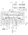
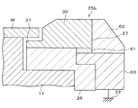
以下,本発明の好ましい実施の形態を,図面を参照にして説明する。図1は,本発明の実施の形態に係るプラズマ処理装置1の概略構成を示す説明図である。図2は,このプラズマ処理装置1が備えるフォーカスリング25を拡大して示した縦断面図である。なお,本明細書および図面において,実質的に同一の機能構成を有する構成要素については,同一の符号を付することにより重複説明を省略する。
Preferred embodiments of the present invention will be described below with reference to the drawings. FIG. 1 is an explanatory diagram showing a schematic configuration of a
気密に構成された円筒形状の処理チャンバー10の内部には,被処理基板である半導体ウエハWを載置させるための下部電極を兼ねる載置台11が配置されている。これら処理チャンバー10と載置台11は,例えばアルミニウム等の導電性材料で構成されている。但し,載置台11は,セラミックなどの絶縁板12を介して処理チャンバー10の底面上に支持されており,処理チャンバー10と載置台11は,互いに電気的に絶縁された状態になっている。
A mounting table 11 that also serves as a lower electrode for mounting a semiconductor wafer W, which is a substrate to be processed, is disposed inside an airtight
載置台11は,上面に置かれた半導体ウエハWを吸着保持するための図示しない静電チャックを備えている。また,載置台11の内部には,温度制御のための熱媒体としての絶縁性流体を循環させるための熱媒体流路15と,ヘリウムガス等の温度制御用のガスを半導体ウエハWの裏面に供給するためのガス流路16が設けられている。このように,熱媒体流路15内に所定温度に制御された絶縁性流体を循環させることによって,載置台11を所定温度に制御し,かつ,この載置台11と半導体ウエハWの裏面との間にガス流路16を介して温度制御用のガスを供給してこれらの間の熱交換を促進し,半導体ウエハWを精度良く効率的に所定温度に制御できるようになっている。
The mounting table 11 includes an electrostatic chuck (not shown) for attracting and holding the semiconductor wafer W placed on the upper surface. Further, inside the mounting table 11, a heat
載置台11には,整合器20を介して,バイアス用の高周波電源(RF電源)21が接続されている。高周波電源21からは,所定の周波数の高周波電圧が載置台11に与えられるようになっている。一方,処理チャンバー10はグランド(アース)22に対して電気的に導通されている。
A high-frequency power source (RF power source) 21 for bias is connected to the mounting table 11 via a
処理チャンバー10の内部において,載置台11の上面の周りには,載置台11上に載置された半導体ウエハWの周囲を囲むようにしてフォーカスリング25が配置されている。このフォーカスリング25は,載置台11の上に直接載せられるリング状の絶縁部材26と,この絶縁部材26の上方に配置されたリング状の導電性部材27で構成されている。絶縁部材26は,例えば,クォーツ,アルミナ等のセラミックス,ベスペル(登録商標)等の樹脂などの絶縁材料(誘電体)からなる。導電性部材27は,例えばSi(導電性を出すためにB等をドープ済みのSi),C,SiC等の導電性材料からなる。
Inside the
図2に示すように,導電性部材27は,載置台11上に載置された半導体ウエハWの周囲外側に配置された外側リング部30と,載置台11上に載置された半導体ウエハWの周縁部下方に所定の間隔を開けて配置されたリング状の内側リング部31を備えている。図示の例では,外側リング部30とリング状の内側リング部31は導電性材料からなる導電性部材27として一体的に形成されているので,外側リング部30と内側リング部31は互いに電気的に導通した状態である。但し,上述のようにリング状の導電性部材27と載置台11の間には絶縁部材26が介在しているので,外側リング部30と内側リング部31は載置台11に対しては電気的に絶縁されている。なお,外側リング部30と内側リング部31の境界を,図2中に点線31’として記入した。この境界31’で示したように,一体的に形成された導電性部材27において,載置台11上に載置された半導体ウエハWの周囲外側に配置された部分が外側リング部30であり,半導体ウエハWの周縁部下方に所定の間隔を開けて配置された部分がリング状の内側リング部31となっている。
As shown in FIG. 2, the
また,このように載置台11に対して絶縁されているリング状の導電性部材27は,処理チャンバー10の内部において絶縁部材26の他には電気的に接触していない。このため,外側リング部30と内側リング部31は,グランド22に対しても電気的に浮いた状態になっている。
Further, the ring-shaped
外側リング部30の上面は,載置台11上に載置された半導体ウエハWの周囲に配置された,外側に向かって次第に高くなる傾斜面部30aと,この傾斜面部30aの外側に連続して形成された水平面部30bとで形成されている。水平面部30bは,載置台11上に載置された半導体ウエハWの上面よりも高く設定されており,傾斜面部30aは,内縁が載置台11上に載置された半導体ウエハWの上面とほぼ等しい高さであって,外側に向かって水平面部30bの高さまで次第に高くなるように設定されている。
The upper surface of the
また,処理チャンバー10の内部において,フォーカスリング25の外側には,多数の排気孔が形成されたリング状の排気リング35が設けられている。この排気リング35を介して,排気ポート36に接続された排気系37の真空ポンプ等により,真空チャンバー10内の処理空間の真空排気が行われるように構成されている。
Further, inside the
一方,載置台11の上方の真空チャンバー10の天井部分には,シャワーヘッド40が,載置台11と平行に対向するように設けられており,これらの載置台11およびシャワーヘッド40は,一対の電極(上部電極と下部電極)として機能するようになっている。また,このシャワーヘッド40には,整合器41を介してプラズマ生成用の高周波電源42が接続されている。
On the other hand, a
シャワーヘッド40は,その下面に多数のガス吐出孔45が設けられている。シャワーヘッド40の内部はガス拡散用空隙47に形成されており,その上部にはガス導入部46を有している。このガス導入部46には,ガス供給配管50が接続されており,このガス供給配管50の他端には,ガス供給系51が接続されている。このガス供給系51は,ガス流量を制御するためのマスフローコントローラ(MFC)52,例えばエッチング用の処理ガス等を供給するための処理ガス供給源53等から構成されている。
The
次に,上記のように構成されたプラズマ処理1によるプラズマ処理の手順について説明する。
まず,真空チャンバー1に設けられた図示しないゲートバルブを開放し,このゲートバルブに隣接して配置されたロードロック室(図示せず)を介して,搬送機構(図示せず)により半導体ウエハWを真空チャンバー10内に搬入し,載置台11上に載置する。そして,搬送機構を真空チャンバー10外へ退避させた後,ゲートバルブを閉じ,真空チャンバー10内を密閉した状態にする。
Next, the procedure of the plasma processing by the
First, a gate valve (not shown) provided in the
この後,排気系37の真空ポンプにより排気ポート36を通じて真空チャンバー10内を所定の真空度に排気しつつ,処理ガス供給源53から,シャワーヘッド40を通じて,真空チャンバー10内に所定の処理ガスを供給する。
Thereafter, a predetermined processing gas is supplied into the
そして,この状態で,高周波電源21から比較的周波数の低いバイアス用の高周波電力を供給すると共に,高周波電源42から比較的周波数の高いプラズマ生成用の高周波電力を供給することにより,図2に示すように,半導体ウエハWの上方において真空チャンバー10内にプラズマPを発生させる。こうして,半導体ウエハWの上方に発生させたプラズマP中のラジカル分子やイオンを半導体ウエハW上面に向けて引き込み,それらの作用により半導体ウエハW上面のプラズマ処理を行う。
In this state, a high frequency power for bias having a relatively low frequency is supplied from the high
そして,所定のプラズマ処理が終了すると,高周波電源21,42からの高周波電力の供給を停止することによって,プラズマ処理を停止し,上述した手順とは逆の手順で,半導体ウエハWを真空チャンバー10外に搬出する。
When the predetermined plasma processing is completed, the plasma processing is stopped by stopping the supply of high-frequency power from the high-
このようなプラズマ処理を行うに際し,この実施の形態のプラズマ処理装置1では,前述したとおり,載置台11に対して絶縁部材26を介して導電性部材27を配置したフォーカスリング25を採用していることから,図3に示すように,半導体ウエハW(載置台11)と導電性部材27と間に電位差Veが生じた状態となる。この場合,半導体ウエハWと導電性部材27と間の静電容量をCeとすれば,電位差Veは静電容量Ceに反比例する。
When performing such plasma processing, the
またプラズマ処理中は,このように半導体ウエハWと導電性部材27との間に電位差Veが生ずることにより,半導体ウエハWと導電性部材27の間には,図4に示す如き電界Eが形成される。この電界Eの等電位面eは,図4に示すように,半導体ウエハWの外周面と外側リング部30の内周面30cの間においてはほぼ垂直方向となり,半導体ウエハWの周縁部下面と内側リング部31の上面との間では,ほぼ水平方向となる。このような等電位面eを有する電界Eの作用により,半導体ウエハWの外周面と外側リング部30の内周面30cの間においては,半導体ウエハWの表面に向けて下向きに引き込んだプラズマP中のイオンIを半導体ウエハWの外周面に向かう方向に加速し,また,半導体ウエハWの周縁部下面と内側リング部31の上面との間においては,プラズマ中のイオンIを半導体ウエハWの周縁部下面に向かう方向に加速することができる。
Further, during the plasma processing, the potential difference Ve is generated between the semiconductor wafer W and the
こうして,プラズマ処理中では,半導体ウエハWと導電性部材27と間の電位差Veによって形成される電界Eの作用で,プラズマ中のイオンIを半導体ウエハWの外周面と周縁部下面に衝突させることにより,半導体ウエハWの外周面と周縁部下面の両方におけるデポジションの発生を低減することができる。
Thus, during plasma processing, the ions I in the plasma collide with the outer peripheral surface and the lower peripheral surface of the semiconductor wafer W by the action of the electric field E formed by the potential difference Ve between the semiconductor wafer W and the
なお,半導体ウエハWの周縁部下面におけるデポジションの発生を低減するためには,半導体ウエハWの外周面と外側リング部30の内周面30cの間においては,プラズマ中のイオンIの全部を半導体ウエハWの外周面に衝突させるのではなく,プラズマ中のイオンIの少なくとも一部は半導体ウエハWの外周面と外側リング部30の内周面30cの間をそのまま下方に通過させて,半導体ウエハWの周縁部下方までイオンIを通過させることが必要となる。そのためには,図2に示すように,載置台11上に載置された半導体ウエハWの外周面とそれに対向する外側リング部30の内周面30cとの間隔L1を,内側リング部31の上面と半導体ウエハWの周縁部の下面との間隔L2よりも広く形成しておく。
In order to reduce the occurrence of deposition on the lower surface of the peripheral edge of the semiconductor wafer W, all the ions I in the plasma are between the outer peripheral surface of the semiconductor wafer W and the inner
かかる構成にすることにより,図4に示した等電位面e同士の間隔を,半導体ウエハWの外周面と外側リング部30の内周面30cの間において相対的に粗にし,半導体ウエハWの周縁部下面と内側リング部31の上面との間において相対的に密にすることができる。これにより,半導体ウエハWの外周面と外側リング部30の内周面30cの間では,半導体ウエハWの外周面に向かう方向への加速を比較的小さくして半導体ウエハWの周縁部下方までイオンIを通過させることができる。また一方,半導体ウエハWの周縁部下面と内側リング部31の上面との間では,半導体ウエハWの周縁部下面に向かう方向への加速を比較的大きくして半導体ウエハWの周縁部下面にイオンIを衝突させ,半導体ウエハWの周縁部下面におけるデポジションの発生を確実に低減できるようになる。
With this configuration, the interval between the equipotential surfaces e shown in FIG. 4 is made relatively rough between the outer peripheral surface of the semiconductor wafer W and the inner
なお,半導体ウエハWの外周面と外側リング部30の内周面30cとの間隔L1および内側リング部31の上面と半導体ウエハWの周縁部の下面との間隔L2の好ましい範囲は,半導体ウエハWと導電性部材27との間に形成される電位差Veの大きさ,半導体ウエハWの径や厚さ,内周面30cの高さなどにより変動するので,一概に定めることはできないが,例えば,半導体ウエハWの外周面と外側リング部30の内周面30cとの間隔L1は1〜5mmであり,2〜2.5mmが望ましい。この間隔L1が小さすぎると,半導体ウエハWの外周面と外側リング部30との間で異常放電を生ずる場合があり,逆に大きすぎると,後述する半導体ウエハW上のプラズマシースと外側リング部30上のプラズマシースが不連続となる可能性がある。
Incidentally, the outer peripheral surface and the preferred range of distance L 2 between the lower surface of the peripheral portion of the upper surface and the semiconductor wafer W intervals L 1 and the
また例えば,内側リング部31の上面と半導体ウエハWの周縁部の下面との間隔L2は0.2〜1mmであり,0.2〜0.5mmが望ましい。この間隔L2が小さすぎると,内側リング部31の上面と半導体ウエハWの周縁部との間で異常放電を生ずる場合があり,逆に大きすぎると,半導体ウエハWの周縁部下面と内側リング部31の上面との間において等電位面e同士の間隔を密にすることができず,イオンIを半導体ウエハWの周縁部下面に向かう方向へ十分に加速できなくなって,半導体ウエハWの周縁部下面におけるデポジションの発生を十分に低減できなくなる。また,このように間隔L2を隔てて対向している内側リング部31の上面と半導体ウエハWの周縁部の下面との対向部分の間隔L4は,0.05〜0.5mmが望ましい。
Further, for example, distance L 2 between the lower surface of the peripheral portion of the upper surface and the semiconductor wafer W of the
また,図示の実施の形態では,プラズマ処理中は,半導体ウエハWと導電性部材27との間に電位差Veが生じるため,半導体ウエハW上にできるプラズマシースと,導電性部材27の外側リング部30上に形成されるプラズマシースの厚さが異なることになる。しかるに,この実施の形態のフォーカスリング25にあっては,上記のように外側リング部30の上面を,外側に向かって次第に高くなる傾斜面部30aと,この傾斜面部30aの外側に連続して形成された半導体ウエハWの上面よりも高い水平面部30bとに形成しているので,半導体ウエハW上と外側リング部30上の境界でのプラズマシース厚さの変動を緩和することができる。これにより,半導体ウエハWの周縁部における電界の急激な変化を抑制して,半導体ウエハWの周縁部においてもプラズマ中のイオンIを半導体ウエハWの上面に対してほぼ垂直に引き込むことができ,プラズマ処理の均一性を高めることができる。また,外側リング部30の上面を傾斜面部30aと水平面部30bとで形成したことにより,フォーカスリング25自体の寿命を長期化させることもできる。
In the illustrated embodiment, since a potential difference Ve is generated between the semiconductor wafer W and the
なお,外側リング部30の上面に形成される傾斜面部30aの高さ方向の範囲hは,半導体ウエハWの上面から高さ0〜6mmの範囲とすることが好ましく,さらに好ましくは2mm〜4mmである。また,傾斜面部30aの水平方向の長さh’(半導体ウエハWの直径方向の長さ)は,0.5〜9mmの範囲とすることが好ましく,さらに好ましい範囲は,1〜6mmである。なお,傾斜面部30aの水平方向の長さh’は,半導体ウエハWの外周面と外側リング部30の内周面30cとの間隔L1によっては,0にすることも可能である。かかる場合は,傾斜面部30aが無い形状となるが,間隔L1を調節することによって半導体ウエハWの周縁部における急激な電界の変化を抑制することもできる。
The range h in the height direction of the
また,プラズマ処理中は,載置台11と導電性部材27と間に電位差Veが生じているので,内側リング部31の内縁が載置台11に近接し過ぎると両者間で異常放電を生じる可能性がある。一方,内側リング部31の内縁を載置台11から離間させ過ぎると,半導体ウエハWの周縁部下方に内側リング部31を十分に侵入させることができなくなり,上述したようなプラズマ中のイオンIの半導体ウエハW周縁部下面への衝突がなくなって,デポジションの低減といった作用効果が十分に得られなくなってしまう。このため,図2に示す内側リング部31の内縁と載置台11との間隔L3は,0.5〜1mmの範囲とすることが好ましい。
Further, during the plasma processing, a potential difference Ve is generated between the mounting table 11 and the
半導体ウエハWと導電性部材27との間の静電容量Ceをどの程度にするかは,実際の個々のプラズマ処理装置に基いて定める必要がある。一般的には,静電容量Ceを小さくすると,半導体ウエハWと導電性部材27との間に形成される電位差Veが大きくなる。よって,半導体ウエハWの周縁部下面と内側リング部31の上面との間において,プラズマ中のイオンIを半導体ウエハWの周縁部下面に向かう方向に加速する力が強くなり,半導体ウエハWの周縁部下面におけるデポジションの発生を低減する効果が増す傾向となる。逆に,静電容量Ceを大きくすると,半導体ウエハWと導電性部材27との間に形成される電位差Veが小さくなる。よって,半導体ウエハWの周縁部下面と内側リング部31の上面との間において,プラズマ中のイオンIを半導体ウエハWの周縁部下面に向かう方向に加速する力が弱くなり,半導体ウエハWの周縁部下面におけるデポジションの発生を低減する効果が減少する傾向となる。
It is necessary to determine how much the electrostatic capacity Ce between the semiconductor wafer W and the
また上述のように,プラズマ処理中に半導体ウエハW上にできるプラズマシースと導電性部材27の外側リング部30上に形成されるプラズマシースの厚さが異なることによって,半導体ウエハWの周縁部におけるイオンIの入射角が影響を受ける。一般的には,静電容量Ceを小さくすると,半導体ウエハWと導電性部材27との間に形成される電位差Veが大きくなって,外側リング部30上に形成されるプラズマシースの厚さが薄くなり,イオンIの入射角は半導体ウエハWの中心に向かう方向に傾斜(入射角>90°)する傾向がある。逆に,静電容量Ceを大きくすると,半導体ウエハWと導電性部材27との間に形成される電位差Veが小さくなって,外側リング部30上に形成されるプラズマシースの厚さが厚くなり,イオンIの入射角は半導体ウエハWの中心から外側に向かうに方向に傾斜(入射角<90°)する傾向がある。
Further, as described above, the plasma sheath formed on the semiconductor wafer W during the plasma processing and the plasma sheath formed on the
ここで,半導体ウエハWと導電性部材27との間の静電容量Ceの変化に対する,半導体ウエハW周縁部下面のポリマー付着量(右縦軸)および半導体ウエハWの周縁部上面におけるイオンIの入射角(左縦軸)の関係をシミュレーションした結果を図5に示した。本発明者らのシミュレーション結果においても,上記傾向がそれぞれ確認された。
Here, with respect to the change in the capacitance Ce between the semiconductor wafer W and the
しかして,この実施の形態のプラズマ処理装置1によれば,半導体ウエハWの周縁部下面側に対するデポジションの発生を従来に比べて低減することができるとともに,半導体ウエハWの周縁部における電界の傾きを抑制することによって,半導体ウエハWの周縁部においても略垂直なエッチングを行うことができ,処理の面内均一性を向上させることができるようになる。
Therefore, according to the
以上,本発明の好ましい実施の形態の一例を示したが,本発明はここに例示した形態に限定されない。例えば,載置台11上に載置された半導体ウエハWの外周面と外側リング部30の内周面30cとの間隔L1を広くするためには,図6に示すフォーカスリング25aのように,半導体ウエハWの外周面と対向している外側リング部30の内周面30cに凹部30dを形成しても良い。このように凹部30dを形成して半導体ウエハWの外周面との間隔L1を十分に広くすることにより,半導体ウエハWの周縁部下方までイオンIをより円滑に通過させることができるようになる。なお,この図6で説明したフォーカスリング25aの場合,外側リング部30の上面において傾斜面部30aは省略することが望ましい。
As mentioned above, although an example of preferable embodiment of this invention was shown, this invention is not limited to the form illustrated here. For example, in order to widen the distance L 1 between the inner
また,図7に示すフォーカスリング25bのように,載置台11に対して絶縁部材26で絶縁されている導電性部材27に,グランド22に電気的に接続した第2の導電性部材60を近接させて配置し,これら導電性部材27と導電性部材60の間に第2の絶縁部材(誘電体)61を介在させても良い。なお,この図7に示す例では,導電性部材27の外側に絶縁材料からなるカバーリング62を設けている。
Further, as in the
このフォーカスリング25bにあっては,プラズマ処理中,図8に示すように,半導体ウエハW(載置台11)と導電性部材27と間に電位差Veが生じると共に,導電性部材27とグランド22(導電性部材60)との間に電位差Vgが生じた状態となる。この場合,半導体ウエハWと導電性部材27と間の静電容量をCe,導電性部材27とグランド22と間の静電容量をCgとすれば,半導体ウエハW(載置台11)と導電性部材27の間の電位差Veは静電容量Ceに反比例し,導電性部材27とグランド22との間の電位差Vgは静電容量Cgに反比例する。そして,これら電位差Ve,Vg,静電容量Ce,Cgの間には次の式(1)〜(3)の関係が成り立つ。
In the
Ve+Vg=Vtotal (1)
Ce×Ve=Cg×Vg (2)
Ve=Cg×Vtotal/(Cg+Ce) (3)
Ve + Vg = V total (1)
Ce × Ve = Cg × Vg (2)
Ve = Cg × V total / (Cg + Ce) (3)
式(3)から,導電性部材27とグランド22と間の静電容量をCgを変えることによって,半導体ウエハW(載置台11)と導電性部材27の間の電位差Veを変化させることができることが分かる。例えば図7に示すフォーカスリング25bにおいては,導電性部材27と第2の導電性部材60との近接距離を変える,導電性部材27と導電性部材60の間に介在させる第2の絶縁部材(誘電体)61の誘電率を変化させる,等の方法によって,導電性部材27とグランド22と間の静電容量をCgを変え,それにより,半導体ウエハW(載置台11)と導電性部材27の間の電位差Veを変化させることが可能である。
From equation (3), the potential difference Ve between the semiconductor wafer W (mounting table 11) and the
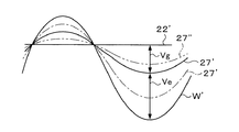
図9を参照にしてこの関係を説明する。図9において,曲線W’は,プラズマ処理中における半導体ウエハWの電位の変化を示し,曲線27’は,プラズマ処理中における導電性部材27の電位の変化を示し,直線22’は,グランド22の電位を示している。図中,曲線W’と曲線27’の幅が,半導体ウエハW(載置台11)と導電性部材27の間の電位差Veであり,曲線27’と直線22’の幅が,導電性部材27とグランド22との間の電位差Vgである。この図9に示したように,導電性部材27とグランド22との間の電位差Vgを大きくした場合は(図9の一点鎖線27’の場合は),半導体ウエハW(載置台11)と導電性部材27の間の電位差Veが小さくなる。逆に,導電性部材27とグランド22との間の電位差Vgを小さくした場合は(図9の二点鎖線27’の場合は),半導体ウエハW(載置台11)と導電性部材27の間の電位差Veが大きくなる。このように,導電性部材27とグランド22との間の電位差Vgを変えることにより,半導体ウエハW(載置台11)と導電性部材27の間の電位差Veを変化させることが可能である。
This relationship will be described with reference to FIG. In FIG. 9, a curve W ′ indicates a change in the potential of the semiconductor wafer W during the plasma processing, a
ここで,図7に示すフォーカスリング27bを用いたプラズマ処理装置1において,半導体ウエハW(載置台11)と導電性部材27の間の電位差Veの変化に対する,半導体ウエハW周縁部下面のポリマー付着量(右縦軸)および半導体ウエハWの周縁部上面におけるイオンIの入射角(左縦軸)の関係をシミュレーションした結果を図10に示した。なお,半導体ウエハW(載置台11)と導電性部材27と間の電位差Veと導電性部材27とグランド22(導電性部材60)と間の電位差Vgの総和(Vtotal)は一定であって,式(3)より,半導体ウエハW(載置台11)と導電性部材27と間の電位差Veは,静電容量比(Cg/(Cg+Ce))に比例しているため,図10中の横軸は,電位差Veに代えて静電容量比(Cg/(Cg+Ce))を用いた。
Here, in the
本発明者らのシミュレーション結果によれば,半導体ウエハWと導電性部材27との間に形成される電位差Veを大きくすると(静電容量比(Cg/(Cg+Ce))を大きくすると),半導体ウエハWの周縁部下面におけるデポジションの発生が低減し,イオンIの入射角が半導体ウエハWの中心に向かう方向に傾斜(入射角>90°)する傾向が見られた。また逆に,半導体ウエハWと導電性部材27との間に形成される電位差Veを小さくすると(静電容量比(Cg/(Cg+Ce))を小さくすると),半導体ウエハWの周縁部下面におけるデポジションの発生が増加し,イオンIの入射角が半導体ウエハWの中心から外側に向かう方向に傾斜(入射角<90°)する傾向が見られた。
According to the simulation results of the present inventors, when the potential difference Ve formed between the semiconductor wafer W and the
また,半導体ウエハWと導電性部材27との間に形成される電位差Veをより容易に変化させるために,図11に示すフォーカスリング25cのように,載置台11に対して絶縁部材26で絶縁されている導電性部材27を,可変容量コンデンサ65を介してグランド22に電気的に接続しても良い。
Further, in order to more easily change the potential difference Ve formed between the semiconductor wafer W and the
このフォーカスリング25cにあっても,先に図7,8で説明したフォーカスリング25bと同様に,プラズマ処理中は半導体ウエハW(載置台11)と導電性部材27と間に電位差Veが生じ,導電性部材27とグランド22(導電性部材60)と間に電位差Vgが生じた状態となる。そして,このフォーカスリング25cによれば,可変容量コンデンサ65を操作して導電性部材27とグランド22と間の静電容量Cgを変えることができるので,それに従って,半導体ウエハW(載置台11)と導電性部材27の間の電位差Veを容易に変化させることが可能である。このように半導体ウエハWと導電性部材27との間に形成される電位差Veを変化させることにより,半導体ウエハWの周縁部下面に対するイオンIの衝突量を容易に調整できるようになる。
Even in the
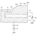
また,半導体ウエハWと導電性部材27との間に形成される電位差Veを変化させるためには,図12に示すフォーカスリング25dのように,載置台11に対して絶縁部材26で絶縁されている導電性部材27に,可変直流電源66を電気的に接続しても良い。
Further, in order to change the potential difference Ve formed between the semiconductor wafer W and the
このフォーカスリング25dにあっても,先に図7,8で説明したフォーカスリング25bと同様に,プラズマ処理中は半導体ウエハW(載置台11)と導電性部材27と間に電位差Veが生じ,導電性部材27とグランド22(導電性部材60)と間に電位差Vgが生じた状態となる。このフォーカスリング25dによれば,可変直流電源66を操作すると,図13に示したように,導電性部材27とグランド22との間の電位差Vgを図中の上下にシフトさせることができる。そして,電位差Vgを図中の下方にシフトさせた場合は(図13中の一点鎖線27’の場合は),半導体ウエハW(載置台11)と導電性部材27の間の電位差Veが小さくなる。逆に,電位差Vgを図中の上方にシフトさせた場合は(図13中の二点鎖線27’の場合は),半導体ウエハW(載置台11)と導電性部材27の間の電位差Veが大きくなる。このように,導電性部材27に接続した,可変直流電源66を操作することにより,半導体ウエハW(載置台11)と導電性部材27の間の電位差Veを容易に変化させることが可能である。
Even in the
また,以上に説明したフォーカスリング27,27a,27b,27c,27dは,何れも,載置台11上の半導体ウエハW周囲外側に配置された外側リング部30と半導体ウエハWの周縁部下方に配置された内側リング部31を,導電性部材27として一体的に形成した形態を示したが,外側リング部30と内側リング部31は,互いに別の部材として構成しても良い。また,そのように互いに別の部材として構成した場合は,外側リング部30と内側リング部31は,互いに電気的に導通していても良いし,互いに電気的に絶縁されていても良い。
The focus rings 27, 27 a, 27 b, 27 c, and 27 d described above are all disposed below the
図14に示すフォーカスリング25eは,載置台11上の半導体ウエハW周囲外側に配置された外側リング部30と,半導体ウエハWの周縁部下方に配置された内側リング部31とが,互いに別の部材として構成され,これら外側リング部30と内側リング部31は,互いに電気的に絶縁された状態になっている。このフォーカスリング25eでは,外側リング部30は載置台11の上に電気的に導通した状態で置かれている。一方,内側リング部31とこれら外側リング部30および載置台11の間には絶縁部材26が介在しているので,内側リング部31は,外側リング部30および載置台11に対して電気的に絶縁されている。
In the
この図14に示すフォーカスリング25eを備えたプラズマ処理1にあっては,プラズマ処理中,外側リング部30は載置台11と常に同じ電位となり,半導体ウエハWと外側リング部30との間には電位差が生じないが,内側リング部31は,載置台11との間に絶縁部材26が介在しているため,載置台11に印加される高周波電力に対するインピーダンスが高くなるので,半導体ウエハWと内側リング部31との間のみに電位差Veが生じた状態となる。このため,半導体ウエハWの周縁部下面と内側リング部31の上面との間に,プラズマ中のイオンIを半導体ウエハWの周縁部下面に向かう方向に加速する電界が形成されて,半導体ウエハWの周縁部下面におけるデポジションの発生を低減できるようになる。加えて,この図14に示すフォーカスリング25eにあっては,半導体ウエハWの外周面と外側リング部30の内周面との間に電位差が生じないので,プラズマ中のイオンIを半導体ウエハWの外周面と外側リング部30の内周面30cの間を円滑に通過させることができ,こうして半導体ウエハWの周縁部下方まで通過させたイオンIを,半導体ウエハWの周縁部下面に衝突させることによって,半導体ウエハWの周縁部下面におけるデポジションの発生を更に低減できるようになる。
In the
また,図1では,プラズマ生成用の比較的周波数の高い高周波電力を,真空チャンバー10の天井部分のシャワーヘッド40(上部電極)に供給する例を示したが,図15に示すように,プラズマ生成用の比較的周波数の高い高周波電力を供給する高周波電源42および整合器41と,バイアス用の比較的周波数の低い高周波電力を供給する高周波電源21および整合器20の両方を,載置台11に接続した構成としても良い。
Further, FIG. 1 shows an example in which high-frequency power having a relatively high frequency for plasma generation is supplied to the shower head 40 (upper electrode) on the ceiling portion of the
また,本発明は,以上に説明したフォーカスリング25,25a,25b,25c,25d,25eを,処理チャンバー10内において載置台11上の半導体ウエハWの周囲を囲むように配置させる適当な支持部材を包含するフォーカスリング部品についても適用される。この場合,フォーカスリング25,25a,25b,25c,25d,25eを支持する支持部材として,例えば,載置台11,排気リング35などが例示される。また,図7で説明した第2の導電性部材60や第2の絶縁部材61を支持部材に利用しても良い。
Further, according to the present invention, an appropriate support member that arranges the focus rings 25, 25 a, 25 b, 25 c, 25 d, and 25 e described above so as to surround the periphery of the semiconductor wafer W on the mounting table 11 in the
本発明は,半導体装置の製造産業において利用することが可能である。 The present invention can be used in the semiconductor device manufacturing industry.
1 プラズマ処理装置
10 処理チャンバー
11 載置台
12 絶縁板
15 熱媒体流路
16 ガス流路
29 整合器
21 高周波電源
22 グランド(アース)
25 フォーカスリング
26 リング状の絶縁部材
27 導電性部材
30 外側リング部
31 内側リング部
30a 傾斜面部
30b 水平面部
35 排気リング
40 シャワーヘッド
41 整合器
42 高周波電源
45 ガス吐出孔
47 ガス拡散用空隙
46 ガス導入部
50 ガス供給配管
51 ガス供給系
52 マスフローコントローラ
53 処理ガス供給源
DESCRIPTION OF
25
Claims (27)
前記載置台上に載置された被処理基板の周囲を囲むように配置されるフォーカスリングを備え,
前記フォーカスリングは,前記載置台上に載置された被処理基板の周囲外側に配置された導電性材料からなる外側リング部と,前記載置台上に載置された被処理基板の周縁部下方に所定の間隔を開けて配置された導電性材料からなる内側リング部を備え,
前記内側リング部と前記載置台の間は電気的に絶縁されていることを特徴とする,プラズマ処理装置。 A plasma processing apparatus for processing a substrate to be processed by placing the substrate to be processed on a mounting table disposed in the processing chamber and generating a plasma in the processing chamber by applying a high frequency voltage.
A focus ring arranged so as to surround the substrate to be processed placed on the mounting table;
The focus ring includes an outer ring portion made of a conductive material arranged on the outer periphery of the substrate to be processed placed on the mounting table, and a lower peripheral portion of the substrate to be processed placed on the mounting table. Provided with an inner ring portion made of a conductive material arranged at a predetermined interval,
The plasma processing apparatus, wherein the inner ring portion and the mounting table are electrically insulated.
前記載置台上に載置された被処理基板の周囲外側に配置される導電性材料からなる外側リング部と,前記載置台上に載置された被処理基板の周縁部下方に所定の間隔を開けて配置される導電性材料からなる内側リング部を備え,
前記内側リング部と前記載置台の間は電気的に絶縁されていることを特徴とする,フォーカスリング。 In a plasma processing apparatus for processing a substrate to be processed by generating a plasma in the processing chamber by applying a high frequency voltage, the plasma processing apparatus is disposed so as to surround the substrate to be processed on a mounting table disposed in the processing chamber. A focus ring,
A predetermined interval is provided below the outer ring portion made of a conductive material disposed on the outer periphery of the substrate to be processed placed on the mounting table, and below the peripheral portion of the substrate to be processed placed on the mounting table. It has an inner ring part made of a conductive material that is placed open,
The focus ring, wherein the inner ring portion and the mounting table are electrically insulated.
前記載置台上に載置された被処理基板の周縁部下方に,前記プラズマで生成されたイオンを被処理基板の周縁部下面に向けて加速させる電界を形成することにより,イオンを被処理基板の周縁部下面に衝突させることを特徴とする,プラズマ処理方法。 A plasma processing method of processing a substrate to be processed by placing the substrate to be processed on a mounting table disposed in the processing chamber and generating a plasma in the processing chamber by applying a high frequency voltage.
By forming an electric field for accelerating the ions generated by the plasma toward the lower surface of the peripheral portion of the substrate to be processed, the ions are generated below the peripheral portion of the substrate to be processed placed on the mounting table. A plasma processing method characterized by causing a collision with the lower surface of the peripheral edge of the substrate.
Priority Applications (8)
| Application Number | Priority Date | Filing Date | Title |
|---|---|---|---|
| JP2006074372A JP2007250967A (en) | 2006-03-17 | 2006-03-17 | Plasma treating apparatus and method, and focus ring |
| US11/685,308 US7988814B2 (en) | 2006-03-17 | 2007-03-13 | Plasma processing apparatus, plasma processing method, focus ring, and focus ring component |
| KR1020070025713A KR20070094522A (en) | 2006-03-17 | 2007-03-15 | Plasma processing apparatus, focus ring, focus ring component and plasma processing method |
| TW096109199A TWI411034B (en) | 2006-03-17 | 2007-03-16 | A plasma processing apparatus and a method and a focusing ring |
| CN2010101475014A CN101807509B (en) | 2006-03-17 | 2007-03-16 | Plasma processing apparatus and focus ring |
| CN2007100883758A CN101038849B (en) | 2006-03-17 | 2007-03-16 | Plasma processing apparatus and method, and focus ring |
| KR1020090008912A KR100959706B1 (en) | 2006-03-17 | 2009-02-04 | Plasma processing apparatus, focus ring, focus ring component and plasma processing method |
| US13/176,407 US20110272100A1 (en) | 2006-03-17 | 2011-07-05 | Plasma processing apparatus, plasma processing method, focus ring, and focus ring component |
Applications Claiming Priority (1)
| Application Number | Priority Date | Filing Date | Title |
|---|---|---|---|
| JP2006074372A JP2007250967A (en) | 2006-03-17 | 2006-03-17 | Plasma treating apparatus and method, and focus ring |
Related Child Applications (1)
| Application Number | Title | Priority Date | Filing Date |
|---|---|---|---|
| JP2012034034A Division JP5313375B2 (en) | 2012-02-20 | 2012-02-20 | Plasma processing apparatus and focus ring and focus ring component |
Publications (2)
| Publication Number | Publication Date |
|---|---|
| JP2007250967A true JP2007250967A (en) | 2007-09-27 |
| JP2007250967A5 JP2007250967A5 (en) | 2009-04-02 |
Family
ID=38594919
Family Applications (1)
| Application Number | Title | Priority Date | Filing Date |
|---|---|---|---|
| JP2006074372A Pending JP2007250967A (en) | 2006-03-17 | 2006-03-17 | Plasma treating apparatus and method, and focus ring |
Country Status (4)
| Country | Link |
|---|---|
| JP (1) | JP2007250967A (en) |
| KR (2) | KR20070094522A (en) |
| CN (2) | CN101807509B (en) |
| TW (1) | TWI411034B (en) |
Cited By (16)
| Publication number | Priority date | Publication date | Assignee | Title |
|---|---|---|---|---|
| JP2009187673A (en) * | 2008-02-01 | 2009-08-20 | Nec Electronics Corp | Plasma treatment device and method |
| JP2010045200A (en) * | 2008-08-13 | 2010-02-25 | Tokyo Electron Ltd | Focus ring, and plasma processing apparatus and method |
| KR20100130155A (en) | 2009-06-02 | 2010-12-10 | 도쿄엘렉트론가부시키가이샤 | Plasma processing apparatus, plasma processing method, recording medium recording a program |
| WO2011142261A1 (en) * | 2010-05-11 | 2011-11-17 | シャープ株式会社 | Dry etching apparatus |
| WO2011142274A1 (en) * | 2010-05-11 | 2011-11-17 | シャープ株式会社 | Dry etching device |
| JP2012209359A (en) * | 2011-03-29 | 2012-10-25 | Tokyo Electron Ltd | Plasma processing equipment |
| JP2014232884A (en) * | 2014-07-29 | 2014-12-11 | 東京エレクトロン株式会社 | Plasma processing apparatus, plasma processing method, and storage medium for storing program for execution thereof |
| WO2015038294A1 (en) * | 2013-09-16 | 2015-03-19 | Applied Materials, Inc. | Epi pre-heat ring |
| JP2016225588A (en) * | 2015-05-27 | 2016-12-28 | 東京エレクトロン株式会社 | Plasma processing device and focus ring |
| JP2020516072A (en) * | 2017-03-31 | 2020-05-28 | マトソン テクノロジー インコーポレイテッドMattson Technology, Inc. | Preventing material deposition on workpieces in processing chambers |
| CN111435635A (en) * | 2019-01-11 | 2020-07-21 | 东京毅力科创株式会社 | Processing method and plasma processing apparatus |
| CN112242290A (en) * | 2019-07-16 | 2021-01-19 | 东京毅力科创株式会社 | Plasma processing method and plasma processing apparatus |
| CN112839422A (en) * | 2020-12-15 | 2021-05-25 | 成都金创立科技有限责任公司 | Insulation structure for multi-pole plasma generator |
| JP2021521326A (en) * | 2018-04-10 | 2021-08-26 | アプライド マテリアルズ インコーポレイテッドApplied Materials,Incorporated | Solving spontaneous arcs during thick film deposition of high temperature amorphous carbon deposits |
| JP2022506672A (en) * | 2018-11-13 | 2022-01-17 | アプライド マテリアルズ インコーポレイテッド | Processing chamber with improved processing at the edges of the board |
| JP2023067386A (en) * | 2021-11-01 | 2023-05-16 | 東京エレクトロン株式会社 | Measuring method and measuring system |
Families Citing this family (21)
| Publication number | Priority date | Publication date | Assignee | Title |
|---|---|---|---|---|
| CN101447394B (en) * | 2007-11-28 | 2012-01-11 | 北京北方微电子基地设备工艺研究中心有限责任公司 | Method for improving back pollution of work piece during manufacturing process of semiconductor |
| WO2009133189A1 (en) * | 2008-05-02 | 2009-11-05 | Oerlikon Trading Ag, Truebbach | Plasma processing apparatus and method for the plasma processing of substrates |
| EP2342951B1 (en) * | 2008-10-31 | 2019-03-06 | Lam Research Corporation | Lower electrode assembly of plasma processing chamber |
| JP2010278166A (en) * | 2009-05-27 | 2010-12-09 | Tokyo Electron Ltd | Annular component for plasma treatment, and plasma treatment device |
| JP5496568B2 (en) * | 2009-08-04 | 2014-05-21 | 東京エレクトロン株式会社 | Plasma processing apparatus and plasma processing method |
| JP5690596B2 (en) * | 2011-01-07 | 2015-03-25 | 東京エレクトロン株式会社 | Focus ring and substrate processing apparatus having the focus ring |
| JP2012169552A (en) * | 2011-02-16 | 2012-09-06 | Tokyo Electron Ltd | Cooling mechanism, processing chamber, component in processing chamber, and cooling method |
| US9412579B2 (en) * | 2012-04-26 | 2016-08-09 | Applied Materials, Inc. | Methods and apparatus for controlling substrate uniformity |
| US20160099162A1 (en) * | 2013-06-26 | 2016-04-07 | Applied Materials, Inc. | Single ring design for high yield, substrate extreme edge defect reduction in icp plasma processing chamber |
| CN104715997A (en) * | 2015-03-30 | 2015-06-17 | 上海华力微电子有限公司 | Focusing ring and plasma processing device provided with same |
| KR102382823B1 (en) * | 2015-09-04 | 2022-04-06 | 삼성전자주식회사 | ring unit having air holes and substrate processing apparatus including the same |
| JP6607795B2 (en) * | 2016-01-25 | 2019-11-20 | 東京エレクトロン株式会社 | Substrate processing equipment |
| JP6698502B2 (en) * | 2016-11-21 | 2020-05-27 | 東京エレクトロン株式会社 | Mounting table and plasma processing device |
| KR102581226B1 (en) * | 2016-12-23 | 2023-09-20 | 삼성전자주식회사 | Plasma processing device |
| KR102063108B1 (en) * | 2017-10-30 | 2020-01-08 | 세메스 주식회사 | Apparatus and method for treating substrate |
| JP7055040B2 (en) * | 2018-03-07 | 2022-04-15 | 東京エレクトロン株式会社 | Placement device and processing device for the object to be processed |
| US11532458B2 (en) * | 2018-05-30 | 2022-12-20 | Toshiba Mitsubishi-Electric Industrial Systems Corporation | Active gas generation apparatus |
| JP2019220497A (en) * | 2018-06-15 | 2019-12-26 | 東京エレクトロン株式会社 | Mounting table and plasma processing device |
| JP7278160B2 (en) * | 2019-07-01 | 2023-05-19 | 東京エレクトロン株式会社 | Etching method and plasma processing apparatus |
| KR102175990B1 (en) * | 2020-01-09 | 2020-11-09 | 하나머티리얼즈(주) | Focus Ring and plasma device including the same |
| US20220051912A1 (en) * | 2020-08-12 | 2022-02-17 | Taiwan Semiconductor Manufacturing Company Limited | Gas flow control during semiconductor fabrication |
Citations (9)
| Publication number | Priority date | Publication date | Assignee | Title |
|---|---|---|---|---|
| JPH05114583A (en) * | 1991-10-22 | 1993-05-07 | Anelva Corp | Dry etching equipment |
| JP2001196357A (en) * | 2000-01-11 | 2001-07-19 | Matsushita Electric Ind Co Ltd | Plasma processing equipment |
| JP2002110652A (en) * | 2000-10-03 | 2002-04-12 | Rohm Co Ltd | Plasma treatment method and its device |
| JP2002246370A (en) * | 2001-02-15 | 2002-08-30 | Tokyo Electron Ltd | Focus ring and plasma processor |
| JP2004096066A (en) * | 2002-07-12 | 2004-03-25 | Tokyo Electron Ltd | Plasma processor and method of calibrating means for variable impedance |
| JP3531511B2 (en) * | 1998-12-22 | 2004-05-31 | 株式会社日立製作所 | Plasma processing equipment |
| JP2004200219A (en) * | 2002-12-16 | 2004-07-15 | Tokyo Electron Ltd | Treatment equipment and treatment method |
| JP2005277369A (en) * | 2003-09-05 | 2005-10-06 | Tokyo Electron Ltd | Focus ring and plasma processing apparatus |
| WO2005124844A1 (en) * | 2004-06-21 | 2005-12-29 | Tokyo Electron Limited | Plasma processing device amd method |
Family Cites Families (10)
| Publication number | Priority date | Publication date | Assignee | Title |
|---|---|---|---|---|
| US6344105B1 (en) * | 1999-06-30 | 2002-02-05 | Lam Research Corporation | Techniques for improving etch rate uniformity |
| JP2001185542A (en) * | 1999-12-27 | 2001-07-06 | Hitachi Ltd | Plasma processing apparatus and plasma processing method using the same |
| US6363882B1 (en) * | 1999-12-30 | 2002-04-02 | Lam Research Corporation | Lower electrode design for higher uniformity |
| US6554954B2 (en) * | 2001-04-03 | 2003-04-29 | Applied Materials Inc. | Conductive collar surrounding semiconductor workpiece in plasma chamber |
| TWI234417B (en) * | 2001-07-10 | 2005-06-11 | Tokyo Electron Ltd | Plasma procesor and plasma processing method |
| US6887340B2 (en) * | 2001-11-13 | 2005-05-03 | Lam Research Corporation | Etch rate uniformity |
| US6896765B2 (en) * | 2002-09-18 | 2005-05-24 | Lam Research Corporation | Method and apparatus for the compensation of edge ring wear in a plasma processing chamber |
| TW200520632A (en) * | 2003-09-05 | 2005-06-16 | Tokyo Electron Ltd | Focus ring and plasma processing apparatus |
| KR100578129B1 (en) * | 2003-09-19 | 2006-05-10 | 삼성전자주식회사 | Plasma etching device |
| JP2005303099A (en) | 2004-04-14 | 2005-10-27 | Hitachi High-Technologies Corp | Plasma processing apparatus and plasma processing method |
-
2006
- 2006-03-17 JP JP2006074372A patent/JP2007250967A/en active Pending
-
2007
- 2007-03-15 KR KR1020070025713A patent/KR20070094522A/en not_active Ceased
- 2007-03-16 CN CN2010101475014A patent/CN101807509B/en active Active
- 2007-03-16 CN CN2007100883758A patent/CN101038849B/en active Active
- 2007-03-16 TW TW096109199A patent/TWI411034B/en active
-
2009
- 2009-02-04 KR KR1020090008912A patent/KR100959706B1/en active Active
Patent Citations (9)
| Publication number | Priority date | Publication date | Assignee | Title |
|---|---|---|---|---|
| JPH05114583A (en) * | 1991-10-22 | 1993-05-07 | Anelva Corp | Dry etching equipment |
| JP3531511B2 (en) * | 1998-12-22 | 2004-05-31 | 株式会社日立製作所 | Plasma processing equipment |
| JP2001196357A (en) * | 2000-01-11 | 2001-07-19 | Matsushita Electric Ind Co Ltd | Plasma processing equipment |
| JP2002110652A (en) * | 2000-10-03 | 2002-04-12 | Rohm Co Ltd | Plasma treatment method and its device |
| JP2002246370A (en) * | 2001-02-15 | 2002-08-30 | Tokyo Electron Ltd | Focus ring and plasma processor |
| JP2004096066A (en) * | 2002-07-12 | 2004-03-25 | Tokyo Electron Ltd | Plasma processor and method of calibrating means for variable impedance |
| JP2004200219A (en) * | 2002-12-16 | 2004-07-15 | Tokyo Electron Ltd | Treatment equipment and treatment method |
| JP2005277369A (en) * | 2003-09-05 | 2005-10-06 | Tokyo Electron Ltd | Focus ring and plasma processing apparatus |
| WO2005124844A1 (en) * | 2004-06-21 | 2005-12-29 | Tokyo Electron Limited | Plasma processing device amd method |
Cited By (30)
| Publication number | Priority date | Publication date | Assignee | Title |
|---|---|---|---|---|
| JP2009187673A (en) * | 2008-02-01 | 2009-08-20 | Nec Electronics Corp | Plasma treatment device and method |
| JP2010045200A (en) * | 2008-08-13 | 2010-02-25 | Tokyo Electron Ltd | Focus ring, and plasma processing apparatus and method |
| KR20100130155A (en) | 2009-06-02 | 2010-12-10 | 도쿄엘렉트론가부시키가이샤 | Plasma processing apparatus, plasma processing method, recording medium recording a program |
| US8426317B2 (en) | 2009-06-02 | 2013-04-23 | Tokyo Electron Limited | Plasma processing apparatus and plasma processing method |
| WO2011142261A1 (en) * | 2010-05-11 | 2011-11-17 | シャープ株式会社 | Dry etching apparatus |
| WO2011142274A1 (en) * | 2010-05-11 | 2011-11-17 | シャープ株式会社 | Dry etching device |
| JP2012209359A (en) * | 2011-03-29 | 2012-10-25 | Tokyo Electron Ltd | Plasma processing equipment |
| US10047457B2 (en) | 2013-09-16 | 2018-08-14 | Applied Materials, Inc. | EPI pre-heat ring |
| WO2015038294A1 (en) * | 2013-09-16 | 2015-03-19 | Applied Materials, Inc. | Epi pre-heat ring |
| KR20160055910A (en) * | 2013-09-16 | 2016-05-18 | 어플라이드 머티어리얼스, 인코포레이티드 | Epi pre-heat ring |
| KR102165518B1 (en) | 2013-09-16 | 2020-10-14 | 어플라이드 머티어리얼스, 인코포레이티드 | Epi pre-heat ring |
| JP2014232884A (en) * | 2014-07-29 | 2014-12-11 | 東京エレクトロン株式会社 | Plasma processing apparatus, plasma processing method, and storage medium for storing program for execution thereof |
| JP2016225588A (en) * | 2015-05-27 | 2016-12-28 | 東京エレクトロン株式会社 | Plasma processing device and focus ring |
| JP2020516072A (en) * | 2017-03-31 | 2020-05-28 | マトソン テクノロジー インコーポレイテッドMattson Technology, Inc. | Preventing material deposition on workpieces in processing chambers |
| US11251026B2 (en) | 2017-03-31 | 2022-02-15 | Mattson Technology, Inc. | Material deposition prevention on a workpiece in a process chamber |
| JP2021521326A (en) * | 2018-04-10 | 2021-08-26 | アプライド マテリアルズ インコーポレイテッドApplied Materials,Incorporated | Solving spontaneous arcs during thick film deposition of high temperature amorphous carbon deposits |
| JP7296456B2 (en) | 2018-11-13 | 2023-06-22 | アプライド マテリアルズ インコーポレイテッド | Process chamber with improved edge processing of substrates |
| JP2022506672A (en) * | 2018-11-13 | 2022-01-17 | アプライド マテリアルズ インコーポレイテッド | Processing chamber with improved processing at the edges of the board |
| CN111435635B (en) * | 2019-01-11 | 2024-04-12 | 东京毅力科创株式会社 | Processing method and plasma processing apparatus |
| US11211229B2 (en) * | 2019-01-11 | 2021-12-28 | Tokyo Electron Limited | Processing method and plasma processing apparatus |
| CN111435635A (en) * | 2019-01-11 | 2020-07-21 | 东京毅力科创株式会社 | Processing method and plasma processing apparatus |
| JP2021015930A (en) * | 2019-07-16 | 2021-02-12 | 東京エレクトロン株式会社 | Plasma processing method and plasma processing apparatus |
| CN112242290A (en) * | 2019-07-16 | 2021-01-19 | 东京毅力科创株式会社 | Plasma processing method and plasma processing apparatus |
| JP7278896B2 (en) | 2019-07-16 | 2023-05-22 | 東京エレクトロン株式会社 | Plasma processing method and plasma processing apparatus |
| US11742180B2 (en) | 2019-07-16 | 2023-08-29 | Tokyo Electron Limited | Plasma processing method and plasma processing apparatus |
| US12125672B2 (en) | 2019-07-16 | 2024-10-22 | Tokyo Electron Limited | Plasma processing method and plasma processing apparatus |
| CN112242290B (en) * | 2019-07-16 | 2024-10-29 | 东京毅力科创株式会社 | Plasma processing method and plasma processing apparatus |
| CN112839422A (en) * | 2020-12-15 | 2021-05-25 | 成都金创立科技有限责任公司 | Insulation structure for multi-pole plasma generator |
| JP2023067386A (en) * | 2021-11-01 | 2023-05-16 | 東京エレクトロン株式会社 | Measuring method and measuring system |
| JP7641878B2 (en) | 2021-11-01 | 2025-03-07 | 東京エレクトロン株式会社 | Measurement method and measurement system |
Also Published As
| Publication number | Publication date |
|---|---|
| KR20070094522A (en) | 2007-09-20 |
| CN101038849A (en) | 2007-09-19 |
| CN101807509B (en) | 2012-07-25 |
| CN101807509A (en) | 2010-08-18 |
| TW200741860A (en) | 2007-11-01 |
| CN101038849B (en) | 2010-05-26 |
| KR100959706B1 (en) | 2010-05-25 |
| KR20090026321A (en) | 2009-03-12 |
| TWI411034B (en) | 2013-10-01 |
Similar Documents
| Publication | Publication Date | Title |
|---|---|---|
| JP2007250967A (en) | Plasma treating apparatus and method, and focus ring | |
| US7988814B2 (en) | Plasma processing apparatus, plasma processing method, focus ring, and focus ring component | |
| JP5602282B2 (en) | Plasma processing apparatus and focus ring and focus ring component | |
| TWI553729B (en) | Plasma processing method | |
| KR101672856B1 (en) | Plasma processing apparatus | |
| US10340174B2 (en) | Mounting table and plasma processing apparatus | |
| US9011635B2 (en) | Plasma processing apparatus | |
| JP6556046B2 (en) | Plasma processing method and plasma processing apparatus | |
| KR102424818B1 (en) | Plasma processing apparatus and focus ring | |
| JP5702968B2 (en) | Plasma processing apparatus and plasma control method | |
| KR102569911B1 (en) | Focus ring and substrate processing apparatus | |
| KR101898079B1 (en) | Plasma processing apparatus | |
| CN102299067B (en) | Substrate processing method | |
| US20100078129A1 (en) | Mounting table for plasma processing apparatus | |
| JP2009224441A (en) | Showerhead and substrate processing apparatus | |
| JP2008244274A (en) | Plasma processing apparatus | |
| TWI475610B (en) | Electrode construction and substrate processing device | |
| KR20010087219A (en) | Plasma processing apparatus and method | |
| KR20200051494A (en) | Placing table, positioning method of edge ring and substrate processing apparatus | |
| KR20100020927A (en) | Focus ring, plasma processing appratus and palasma processing method | |
| JP4935149B2 (en) | Electrode plate for plasma processing and plasma processing apparatus | |
| JP5313375B2 (en) | Plasma processing apparatus and focus ring and focus ring component | |
| JP2017126727A (en) | Structure of mounting table and semiconductor processing device | |
| JP6570971B2 (en) | Plasma processing apparatus and focus ring | |
| KR20200051505A (en) | Placing table and substrate processing apparatus |
Legal Events
| Date | Code | Title | Description |
|---|---|---|---|
| A521 | Written amendment |
Free format text: JAPANESE INTERMEDIATE CODE: A523 Effective date: 20090213 |
|
| A621 | Written request for application examination |
Free format text: JAPANESE INTERMEDIATE CODE: A621 Effective date: 20090213 |
|
| A977 | Report on retrieval |
Free format text: JAPANESE INTERMEDIATE CODE: A971007 Effective date: 20090727 |
|
| A131 | Notification of reasons for refusal |
Free format text: JAPANESE INTERMEDIATE CODE: A131 Effective date: 20110913 |
|
| A521 | Written amendment |
Free format text: JAPANESE INTERMEDIATE CODE: A523 Effective date: 20111114 |
|
| A131 | Notification of reasons for refusal |
Free format text: JAPANESE INTERMEDIATE CODE: A131 Effective date: 20111220 |
|
| A521 | Written amendment |
Free format text: JAPANESE INTERMEDIATE CODE: A523 Effective date: 20120220 |
|
| A02 | Decision of refusal |
Free format text: JAPANESE INTERMEDIATE CODE: A02 Effective date: 20120313 |