JP2007248003A - Hot water supply heat source machine - Google Patents
Hot water supply heat source machine Download PDFInfo
- Publication number
- JP2007248003A JP2007248003A JP2006074382A JP2006074382A JP2007248003A JP 2007248003 A JP2007248003 A JP 2007248003A JP 2006074382 A JP2006074382 A JP 2006074382A JP 2006074382 A JP2006074382 A JP 2006074382A JP 2007248003 A JP2007248003 A JP 2007248003A
- Authority
- JP
- Japan
- Prior art keywords
- hot water
- heat source
- water supply
- water
- heat
- Prior art date
- Legal status (The legal status is an assumption and is not a legal conclusion. Google has not performed a legal analysis and makes no representation as to the accuracy of the status listed.)
- Pending
Links
Images


Abstract
Description
本発明は例えば病院、老人福祉施設、ホテルなどの比較的多量の湯を使用する大容量給湯システムに係り、特に給湯システム構成機器の設置自由度を拡大することが出来る給湯システムに関する。 The present invention relates to a large-capacity hot water supply system that uses a relatively large amount of hot water, such as a hospital, an elderly welfare facility, and a hotel, and more particularly to a hot water supply system that can expand the degree of freedom of installation of hot water supply system components.
従来、ファミリーレストラン、老人福祉施設あるいはビジネスホテルなど大量に湯を使用する業態に使用される給湯システムとして、多数の熱源機と密閉型タンクを組み合わせたヒートポンプ給湯機が提案されている。 2. Description of the Related Art Conventionally, a heat pump water heater that combines a large number of heat source machines and a sealed tank has been proposed as a hot water system used in a business type that uses a large amount of hot water, such as a family restaurant, a welfare facility for the elderly, or a business hotel.
特許文献1の図4には熱源機を取り付けた複数の密閉型タンクと、電気ヒータを取り付けた開放型タンクを直列に組み合わせた給湯システムが提案されている。
FIG. 4 of
このような密閉型タンクを多数使用システムは大きな据付スペースが必要であるとともに、大容量システムとしての価格が高くなる問題がある。 Such a system using a large number of sealed tanks has a problem that a large installation space is required and the price as a large-capacity system increases.
また、このようなシステムに使用される従来の給湯システムは、図10に示すように、ヒートポンプサイクル72を備えた熱源機73と密閉型タンク74を組み合わせ、熱源機73で生成した湯を湯供給ポンプ75、水配管76を介して密閉タンク74に貯留し、給湯栓から給湯している。
Further, as shown in FIG. 10, the conventional hot water supply system used in such a system combines a
そして、熱源機73は筐体82内に、ヒートポンプサイクルを構成する圧縮機77、四方弁78、減圧機構79、熱源側熱交換器80、水熱交換器83等のサイクル構成要素81を収容している。
The
このような給湯システム71では、熱源機73と密閉型タンク74を水配管76で連通しているため、湯供給ポンプ75のポンプ容量の関係上、水配管76の長さには制約があり、従って、据付場所が限定される。また、熱源機73は屋外に設置する場合、水配管を屋外に敷設する必要があり、これに加えて、寒冷地においては、凍結防止が必要となる。
本発明は上述した事情を考慮してなされたもので、大容量の給湯ができ、給湯システム構成機器の設置自由度を拡大することが出来るとともに据付けが容易で、省エネルギー性に優れた給湯システムを提供することを目的とする。 The present invention has been made in consideration of the above-described circumstances, and can provide a hot water supply system that can supply a large volume of hot water, can increase the degree of freedom of installation of hot water supply system components, is easy to install, and is excellent in energy saving. The purpose is to provide.
上述した目的を達成するため、本発明に係る給湯システムは、圧縮機、水熱交換器、減圧機構、熱源側空気熱交換器を順次配管接続した冷媒回路を構成するヒートポンプ給湯装置の水熱交換器で湯を生成し供給する給湯熱源機と、この給湯熱源機の水熱交換ユニットと水配管を介して接続し、水熱交換器で生成した湯を供給して貯留する密閉型タンクと、この密閉型タンクと水配管を介して接続し密閉型タンクから供給される湯を貯留する開放型タンクと、この開放型タンクに接続され給湯ポンプにより開放型タンクの湯を供給する給湯管路とを備え、給湯熱源機は、上記圧縮機、熱源側空気熱交換器、減圧機構を筐体内に収納した熱源ユニットと、水熱交換器を筐体内に収納した水熱交換ユニットとより構成するとともに、該熱源ユニットと水熱交換ユニットとを冷媒配管で連結して筐体を結合して一体化あるいは分離して配置可能に構成させたことを特徴とする。 In order to achieve the above-described object, a hot water supply system according to the present invention includes a compressor, a water heat exchanger, a pressure reducing mechanism, and a heat heat exchange of a heat pump water heater that constitutes a refrigerant circuit in which a heat source side air heat exchanger is connected in order. A hot water supply heat source device that generates and supplies hot water in a water heater, a sealed tank that supplies and stores hot water generated by a water heat exchanger connected to a water heat exchange unit of the hot water heat source device through a water pipe, An open tank connected to the closed tank via a water pipe and storing hot water supplied from the closed tank; a hot water supply line connected to the open tank for supplying hot water from the open tank by a hot water pump; A hot water supply heat source machine is composed of the compressor, a heat source side air heat exchanger, a heat source unit in which the decompression mechanism is housed in a housing, and a water heat exchange unit in which a water heat exchanger is housed in the housing. , The heat source unit A water heat exchanger unit, characterized in that is configured to be integrally positioned with or separate by combining linked by refrigerant pipes housing.
本発明に係る給湯熱源機によれば、ヒートポンプ給湯熱源機と、水熱交換器で生成した湯を供給して貯留する密閉型タンクと、密閉型タンクから供給される湯を貯留する開放型タンクとから構成する給湯システムにより、据付けが容易で、大容量の給湯ができ、圧縮機、減圧機構、熱源側熱交換器等を収容する熱源ユニットと水熱交換器を収納する水熱交換ユニットとに分離可能とし、冷媒配管を用いて接続することで、熱源機を屋外などに設置する場合にも、熱源機と密閉型タンク間に長い水配管を設ける必要がなく、寒冷地などにおいては、凍結する可能性のある水熱交換ユニットなどの水配管部分を屋外設置される熱源機と分離して屋内に設置することが可能となるなど給湯熱源機の各ユニットの配置位置の自由度を拡大した給湯システムを提供することができる。 According to the hot water supply heat source device according to the present invention, a heat pump hot water supply heat source device, a sealed tank for supplying and storing hot water generated by the water heat exchanger, and an open type tank for storing hot water supplied from the sealed tank A hot water supply system that is easy to install and can supply large volumes of water, a heat source unit that houses a compressor, a decompression mechanism, a heat source side heat exchanger, etc., and a water heat exchange unit that houses a water heat exchanger, By connecting with a refrigerant pipe, it is not necessary to provide a long water pipe between the heat source machine and the sealed tank, even in a cold district. Expanding the degree of freedom of the location of each unit of hot water heat source equipment, such as the possibility of freezing water piping parts such as water heat exchange units that can freeze and installing them indoors separately from the heat source equipment installed outdoors Hot water supply cis It is possible to provide a beam.
本発明の第1実施形態に係る給湯熱源機を給湯システムに組み込んだ例により添付図面を参照して説明する。 An example in which the hot water supply heat source apparatus according to the first embodiment of the present invention is incorporated in a hot water supply system will be described with reference to the accompanying drawings.
図1は本発明の第1実施形態に係る給湯熱源機を組み込んだ給湯システムの概念図である。 FIG. 1 is a conceptual diagram of a hot water supply system incorporating a hot water supply heat source apparatus according to the first embodiment of the present invention.
図1に示すように、はじめに、給湯熱源機の熱源ユニットと水熱交換ユニットを近接した状態で設置する例で説明する。 As shown in FIG. 1, first, an example will be described in which a heat source unit of a hot water supply heat source unit and a water heat exchange unit are installed close to each other.
第1実施形態の給湯熱源機1は、湯を生成するヒートポンプサイクル2を備え、給湯システム3に組み込まれて使用され、通常、給湯システム3は給湯熱源機1とこの給湯熱源機1で生成した湯を貯留する密閉型タンク4とが比較的近接して設置される。
The hot water supply
給湯熱源機1は水配管5を介して接続された密閉型タンク4と、この密閉型タンク4と給湯管6を介して接続され密閉型タンク4から供給される湯を貯留する開放型タンク7と、この開放型タンク7に接続され給湯ポンプ8により開放型タンク7の湯を供給する給湯管路9と、この給湯管路9に接続された多数の給湯栓10、循環ポンプ11及び再加熱装置12を備えた給湯用循環路13を備える。なお、密閉型タンク4には外部給水管路14、減圧弁15を介して適宜水が補給される。
The hot water
また、給湯熱源機1は熱源ユニット16と水熱交換ユニット17からなり、熱源ユニット16と水熱交換ユニット17を冷媒配管18で接続して形成されるヒートポンプサイクル2を備える。
The hot water supply
熱源ユニット16は、圧縮機19、四方弁20、熱源側熱交換器21、減圧機構22、第1の冷媒配管継手23などを第1の筐体25に収容してなり、水熱交換ユニット17は、水熱交換器26、第2の冷媒配管継手27及び給水ポンプ28を第2の筐体29に収容してなり、圧縮機19、四方弁20、水熱交換器26、減圧機構22、熱源側熱交換器21、四方弁20、圧縮機19が両管継手23、27を介して冷媒配管18を用いて順次配管接続されたヒートポンプサイクル2を形成する。
The
例えば、熱源ユニット16と水熱交換ユニット17を近接した状態で、さらに、水熱交換ユニット17に比較的近接した状態で密閉型タンク4、開放型タンク7の全てを地上或いは建物の屋上に設置する。
For example, in a state where the
この場合、熱源ユニット16と水熱交換ユニット17とは、ヒートポンプサイクル2の両管継手23、27間を短い冷媒配管18で接続し、さらに、水熱交換ユニット17と密閉タンク4とは、水熱交換ユニット17側の第1の水配管接続口30、密閉タンク4側の第2の水配管接続口31間を、比較的短い湯管5hと水管5wからなる水配管5で接続し、密閉型タンク4と開放型タンク7とは、給湯管6で接続する。
In this case, the
従って、水配管5は、長い配管が必要なく、給湯システム全体を一箇所に集中して配置できる。 Accordingly, the water pipe 5 does not require a long pipe, and the entire hot water supply system can be concentrated and arranged at one place.
また、給湯熱源機の熱源ユニットと水熱交換ユニットを遠隔した状態で設置する例を図2により説明する。 An example in which the heat source unit of the hot water supply heat source unit and the water heat exchange unit are installed remotely will be described with reference to FIG.
例えば、図2は、給湯を1階を中心に実施するため、密閉型タンク4及び開放型タンク7を地上に設置し、水熱交換ユニット17を密閉型タンク4を近接して配置すると共に、熱源ユニット16のみ、他の空調機の室外機(図示せず)等と共に屋上に設置するケースを示している。
For example, in FIG. 2, in order to perform hot water supply mainly on the first floor, the closed
この場合、熱源ユニット16と水熱交換ユニット17との間を接続する冷媒配管18を長く構成させ、水熱交換器26と密閉型タンク4を接続する水配管5、および密閉型タンク4と開放型タンク7を接続する給湯管6を比較的短く構成させる。
In this case, the
従って、冷媒が流れる配管18は、比較的容易に所定の高さおよび長さに対応できるため熱源ユニット16と水熱交換ユニット17との間が離れていても、性能的に影響を与える事が少ないため、給湯システムの据付場所の設置許容範囲を拡大することが出来る。また、冷媒管は、水配管のように寒冷地においても、凍結することがないため、凍結防止策を必要としない。
Therefore, since the
なお、給湯熱源機の熱源ユニットと水熱交換ユニットを遠隔した状態で設置する例は、図2に示すもののみではなく、例えば、図2の設置例とは逆に、熱源ユニットを地上に設置し、水熱交換ユニットと密閉型タンク4及び開放型タンク7を建物の屋上に設置するものでも同様である。この場合は、開放型タンク7を建物の屋上に設置することで、各階への湯の供給を上方から行えると言った効果がある。
In addition, the example which installs the heat source unit of a hot-water supply heat source machine and a water heat exchange unit in the remote state is not only what is shown in FIG. 2, for example, the heat source unit is installed on the ground contrary to the installation example of FIG. The same applies to the case where the water heat exchange unit, the sealed
また、給湯熱源機1は熱源ユニット16と水熱交換ユニット17に予め分離されているが、図3に示すように、1つの底板33に、熱源ユニット16と水熱交換ユニット17を載置して一体的に取り付けておけば、工場出荷時、物流上便利であり、さらに、熱源ユニット16と水熱交換ユニット17を近接した状態で設置する場合には、底板33に取り付けたまま設置でき、設置作業が容易になる。なお、熱源ユニット16と水熱交換ユニット17を離間した状態で設置する場合には、水熱交換ユニット17を取付底板33から取り外して設置する。
The hot water supply
次に、第1実施形態の給湯熱源機を用いた給湯システムの沸き上げ運転に付いて説明する。 Next, the boiling operation of the hot water supply system using the hot water supply heat source device of the first embodiment will be described.
図1及び図2に示すように、ヒートポンプサイクル2は、圧縮機19で高温、高圧に圧縮された冷媒が、冷媒配管18を介して、水熱交換器26に流入して凝縮し放熱する。凝縮され液化した冷媒は、膨張弁などで構成する減圧装置22で減圧され、熱源側熱交換器21に流入した冷媒は蒸発し、大気から熱を奪ってガス化し、圧縮機19の吸込側に導入される運転が行われる。
As shown in FIGS. 1 and 2, in the
一方、水熱交換器26には、水管5wを介して、密閉型タンク4から水が供給され、この比較的低温の水は、上記水熱交換器26でヒートポンプサイクル2の高温、高圧の冷媒と熱交換して、高温の湯に沸き上げられ、湯管5hを介して、密閉型タンク4に供給される。
On the other hand, water is supplied from the sealed
さらに、密閉型タンク4に供給された湯が所定量貯まると、密閉型タンク4より開放型タンク7に湯が供給され、開放型タンク7に供給された湯は、給湯栓10の給湯要求により、給湯ポンプ8により、給湯用循環路13に供給され、さらに給湯用循環路13に形成する給湯栓10から所望の温度の湯が提供される。
Further, when a predetermined amount of hot water supplied to the sealed
また、給湯が終了し次の給湯要求があるまで、給湯用循環路13に湯が滞留し、湯が所定の温度より低くなると、再加熱装置12を作動させて加熱し、所定の温度以上に保つ。
Also, until hot water is finished and the next hot water supply request is made, hot water stays in the hot water
上記のように給湯熱源機1で沸き上げた湯は、密閉型タンク4に供給されて、この密閉型タンク4内に湯を貯留し、密閉型タンク4内で所定温度以上の湯が貯えられたところで、開放型タンク7に供給され、この開放型タンク7に湯を貯留するようにしたため、給湯熱源機1は単体では大容量のものでなくても、システムの容量に応じて複数台を並列接続することで大容量システム対応が可能となる。
The hot water boiled in the hot water supply
第1実施形態の給湯熱源機によれば、熱源ユニット16と水熱交換ユニット17を分離し、冷媒配管で接続する事で、熱源ユニット16と水熱交換ユニット17との設置距離を自由に設定することができ、熱源機1を屋外などに設置し、密閉型タンク4を屋内など分離して配置する場合にも、熱源機1と密閉型タンク4間に長い水配管を設ける必要がなく、据付場所の自由度が大きく、寒冷地にも適する給湯熱源機が実現する。
According to the hot water supply heat source apparatus of the first embodiment, the installation distance between the
次に、本発明の第2実施形態に係る給湯熱源機について説明する。 Next, a hot water supply heat source apparatus according to the second embodiment of the present invention will be described.
本第2実施形態は、第1実施形態の水熱交換器26の水加熱管26aと密閉型タンク4からの水配管との流路の接続を選択的に切換えるバイパス路を設ける。
In the second embodiment, a bypass path is provided for selectively switching the connection between the
図4に示すように、第2実施形態の給湯熱源機41は、水熱交換器26の水加熱管26aの入口側の水管5wと給水ポンプ28との間に第1の3方弁43を、また水加熱管26aの出口側と湯管5hとの間に第2の3方弁44を夫々介在させ、さらに、この両3方弁43、44の切換え流路に第1のバイパス46及び第2のバイパス47が設けられる構成としている。この両3方弁43、44の連動した切換えにより、通常は水熱交換器26の水加熱管26aの水の流れを、水管5wが入口側、湯管5hが出口側と連通するように構成し、除湿運転時は、両3方弁43、44の切換えにより水加熱管26aの水の流れを、湯管5hが入口側、水管5wが出口側と連通するように構成する。
As shown in FIG. 4, the hot water supply
この構成により、図4中、沸き上げ運転時は、実線矢印に示す水の流れのように密閉タンク4からの水を水管5wから水熱交換器26の水加熱管26aに導き加熱して湯管5hを介して密閉タンク4に戻すように運転され、熱源機41の熱源側熱交換器21の除霜運転時は、点線矢印に示す水の流れのように密閉タンク4の湯を湯管5hから水熱交換器26の水加熱管26aに導き、湯により水熱交換器26に流れる冷媒を加熱する。
With this configuration, during the boiling operation in FIG. 4, the water from the sealed
また、上記と同様に、図4中、ヒートポンプサイクル2は、沸き上げ運転時は、実線矢印に示すように冷媒が流れ、水熱交換器26を凝縮器、熱源側熱交換器21を蒸発器として作用させることで、室外の空気熱源を吸収する運転を行い、また除霜運転時は、四方弁20の切換えにより逆サイクルとし、水熱交換器26を蒸発器、熱源側熱交換器21を凝縮器として作用させることで、密閉タンク4の湯の熱源を利用する運転を行う。
4, in the
これにより、除霜運転時、凝縮器として作用し着霜した熱源側熱交換器21に高温、高圧の冷媒を流し、蒸発器として作用する水熱交換器26を密閉型タンク4からの湯により加熱することで、迅速な除霜が行える。
Accordingly, during the defrosting operation, a high-temperature and high-pressure refrigerant is caused to flow through the heat source
なお、熱源ユニットと水熱交換ユニットは、近接した状態で設置、分離して遠隔した状態に設置することが出来ることは、第1実施形態と同様である。 Note that the heat source unit and the water heat exchange unit can be installed in a close state, separated, and installed in a remote state, as in the first embodiment.
他の構成は図1に示す給湯熱源機と異ならないので、同一符号を付して説明は省略する。 Since the other structure is not different from the hot water supply heat source device shown in FIG.
次に、本発明の第3実施形態に係る給湯熱源機について説明する。 Next, a hot water supply heat source apparatus according to a third embodiment of the present invention will be described.
本第3実施形態は、第2実施形態が1個の給湯熱源機を用いるのに対して、複数個の給湯熱源機を用いる。 The third embodiment uses a plurality of hot water supply heat source devices, whereas the second embodiment uses one hot water supply heat source device.
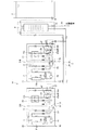
図5に示すように、第3実施形態の給湯熱源機51は、複数個例えば2個の給湯熱源機51A、51Bに図4の第2実施形態の給湯熱源機41で説明した第1、第2の3方弁43、44と同等の機能を有する第1の3方弁43a、43bと、第2の3方弁44a、44bとを備え、さらに、各給湯熱源機51A、51Bを密閉型タンク4に対して並列に接続する。
As shown in FIG. 5, the hot water supply
これにより、凝縮器として作用し着霜した熱源側熱交換器21a、21bに高温、高圧の冷媒を流し、蒸発器として作用する水熱交換器26a、26bを密閉型タンク4からの湯により加熱することで実施する除霜運転を各熱源機毎に順番に行い他の熱源機を沸き上げ運転することで、迅速な除霜が行えるとともに、熱源機は大容量のものでなくても、システムの容量に応じて複数台を並列接続することで除霜運転時でも密閉型タンク4の湯の温度低下を抑えることが出来ると共に、大容量のシステム対応が可能となる。
As a result, high-temperature and high-pressure refrigerant flows through the frosted heat source
また、本発明の第4実施形態に係る給湯熱源機について説明する。 Moreover, the hot water supply heat source machine which concerns on 4th Embodiment of this invention is demonstrated.
本第4実施形態は、第1実施形態の水熱交換ユニットに密閉型タンクとして機能する比較的小容量の密閉型タンクを内蔵させたものである。 In the fourth embodiment, a relatively small-capacity sealed tank that functions as a sealed tank is built in the hydrothermal exchange unit of the first embodiment.
例えば、密閉型タンクを給湯熱源機に近接した状態で設置した例で示す。 For example, an example is shown in which a sealed tank is installed in a state close to a hot water supply heat source machine.
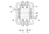
図6及び図7に示すように、第4実施形態の給湯熱源機61は、熱源ユニット16と、この熱源ユニット16に近接設置された水熱交換ユニット17からなり、この水熱交換ユニット17には円筒形状の密閉型タンク62を組み込み、冷媒と湯水が対向流に流れるように配された冷媒管63rと水加熱管63hで構成される水熱交換器63が伝熱的に密着した状態で密閉型タンク62に巻装される。また、水熱交換器63と密閉型タンク62を断熱材64により覆い、沸き上げ効率の向上を図っている。
As shown in FIGS. 6 and 7, the hot water supply
密閉型タンク62には、上部に水加熱管63hと連通する湯受口62a、開放型タンクへの給湯管6と連通する給湯口62bが設けられ、下部には外部給水管路14と連通する給水受口62c、水加熱管63hと連通する除霜時湯受口62dが設けられている。
The sealed
水熱交換ユニット17における水の流路は次のように形成される。
The water flow path in the water
例えば、沸き上げ時の流路として、図8に示すように、減圧弁15を介して外部給水管路14に接続される第1の3方弁43は、給水ポンプ28を介して水加熱管63hの入口に接続され、この水加熱管63hの出口は第2の3方弁44に接続され、この第2の3方弁44は給湯口62aに接続される。従って、沸き上げ時、第1の3方弁43を介して給水された水は給水ポンプ28により、水加熱管63hに導入され、高温、高圧の冷媒が流れる冷媒配管63rと熱交換して、沸き上げられ、第2の3方弁44、湯受口62aを介して、密閉型タンク62に貯留される。
For example, as shown in FIG. 8, the first three-
一方、除霜時の流路として、図9に示すように、第1の3方弁43と第2の3方弁44とを切り換えることで、湯受口62aと第1のバイパス65を介して接続される第1の3方弁43は、給水ポンプ28を介して水加熱管63hの入口に接続され、この水加熱管63hの出口は第2の3方弁44に接続され、この第2の3方弁44は第2のバイパス66を介して除霜時湯受口62dに接続される。従って、除霜時、密閉タンク62内の湯を湯受口62aを介して第1のバイパス65に流れ、さらに、第1の3方弁43、給水ポンプ28を介して、水加熱管63hの入口に導入され、低温、低圧の冷媒が流れる冷媒管63rと熱交換して、湯温が低下し、第2の3方弁44、第2のバイパス66を介して除霜時湯受口62dから密閉型タンク62に流入する。沸き上げ運転時に、着霜した熱源側熱交換器21に高温、高圧の冷媒を流して行う逆サイクル除霜運転時、蒸発器として作用する冷媒管63rの熱源として作用させる事で、迅速な除霜を行うことができる。
On the other hand, as shown in FIG. 9, the flow path for defrosting is switched between the first three-
また、水熱交換器63と密閉型タンク62が一体的に設けられるので、熱源ユニット16を水熱交換ユニット17から遠隔して設置する場合にも、水熱交換器63と密閉型タンク62間に長い水配管を必要とせず、給湯システムの据付場所が限定されず、寒冷地において、凍結することがなく凍結防止策を必要としない。
In addition, since the
1…給湯熱源機、2…ヒートポンプサイクル、3…給湯システム、4…密閉型タンク、5…水配管、5h…湯管、5w…水管、6…給湯管、7…開放型タンク、8…給湯ポンプ、14…外部給水管路、16…熱源ユニット、17…水熱交換ユニット、18…冷媒配管、21…熱源側熱交換器、25…第1の筐体、26…水熱交換器、29…第2の筐体、33…底板。
DESCRIPTION OF
Claims (5)
この給湯熱源機の水熱交換ユニットと水配管を介して接続し、水熱交換器で生成した湯を供給して貯留する密閉型タンクと、
この密閉型タンクと水配管を介して接続し密閉型タンクから供給される湯を貯留する開放型タンクと、
この開放型タンクに接続され給湯ポンプにより開放型タンクの湯を供給する給湯管路とを備え、
給湯熱源機は、上記圧縮機、熱源側空気熱交換器、減圧機構を筐体内に収納した熱源ユニットと、
水熱交換器を筐体内に収納した水熱交換ユニットとより構成するとともに、
該熱源ユニットと水熱交換ユニットとを冷媒配管で連結して筐体を結合して一体化あるいは分離して配置可能に構成させたことを特徴とする給湯システム。 A hot water supply heat source machine that generates and supplies hot water with a water heat exchanger of a heat pump hot water supply apparatus that constitutes a refrigerant circuit in which a compressor, a water heat exchanger, a decompression mechanism, and a heat source side air heat exchanger are connected in series, and
A sealed tank that is connected to a water heat exchange unit of this hot water supply heat source unit through a water pipe and supplies and stores hot water generated by the water heat exchanger,
An open type tank that stores hot water supplied from the sealed tank connected to the sealed tank via a water pipe,
A hot water supply line connected to the open tank and supplying hot water from the open tank by a hot water pump;
The hot water supply heat source machine includes a heat source unit in which the compressor, the heat source side air heat exchanger, and the pressure reducing mechanism are housed in a housing;
The water heat exchanger is composed of a water heat exchange unit housed in a housing, and
A hot water supply system characterized in that the heat source unit and the water heat exchange unit are connected by a refrigerant pipe and a casing is combined to be integrated or separated so as to be arranged.
Priority Applications (1)
| Application Number | Priority Date | Filing Date | Title |
|---|---|---|---|
| JP2006074382A JP2007248003A (en) | 2006-03-17 | 2006-03-17 | Hot water supply heat source machine |
Applications Claiming Priority (1)
| Application Number | Priority Date | Filing Date | Title |
|---|---|---|---|
| JP2006074382A JP2007248003A (en) | 2006-03-17 | 2006-03-17 | Hot water supply heat source machine |
Publications (1)
| Publication Number | Publication Date |
|---|---|
| JP2007248003A true JP2007248003A (en) | 2007-09-27 |
Family
ID=38592508
Family Applications (1)
| Application Number | Title | Priority Date | Filing Date |
|---|---|---|---|
| JP2006074382A Pending JP2007248003A (en) | 2006-03-17 | 2006-03-17 | Hot water supply heat source machine |
Country Status (1)
| Country | Link |
|---|---|
| JP (1) | JP2007248003A (en) |
Cited By (1)
| Publication number | Priority date | Publication date | Assignee | Title |
|---|---|---|---|---|
| JP2011052915A (en) * | 2009-09-02 | 2011-03-17 | Daikin Industries Ltd | Hot water supply system |
Citations (10)
| Publication number | Priority date | Publication date | Assignee | Title |
|---|---|---|---|---|
| JPS61191829A (en) * | 1985-02-21 | 1986-08-26 | Matsushita Electric Ind Co Ltd | Solar heat collecting device |
| JPH0618092A (en) * | 1992-07-06 | 1994-01-25 | Mitsubishi Electric Corp | Centralized hot-water supplying device |
| JPH074692A (en) * | 1993-06-16 | 1995-01-10 | Mitsubishi Heavy Ind Ltd | Outdoor unit of air conditioner |
| JP2003156253A (en) * | 2001-11-16 | 2003-05-30 | Sanyo Electric Co Ltd | Heat pump type water heating equipment |
| JP2003240340A (en) * | 2002-02-12 | 2003-08-27 | Matsushita Electric Ind Co Ltd | Heat pump hot water supply system |
| JP2004053153A (en) * | 2002-07-22 | 2004-02-19 | Sanyo Electric Co Ltd | Heat pump device |
| JP2004183908A (en) * | 2002-11-29 | 2004-07-02 | Toshiba Electric Appliance Co Ltd | Heat pump water heater |
| JP2005090815A (en) * | 2003-09-16 | 2005-04-07 | Matsushita Electric Ind Co Ltd | Heat pump water heater |
| JP2005315480A (en) * | 2004-04-28 | 2005-11-10 | Hitachi Home & Life Solutions Inc | Heat pump type water heater |
| WO2005106346A1 (en) * | 2004-04-28 | 2005-11-10 | Toshiba Carrier Corporation | Heat pump-type hot water supply apparatus |
-
2006
- 2006-03-17 JP JP2006074382A patent/JP2007248003A/en active Pending
Patent Citations (10)
| Publication number | Priority date | Publication date | Assignee | Title |
|---|---|---|---|---|
| JPS61191829A (en) * | 1985-02-21 | 1986-08-26 | Matsushita Electric Ind Co Ltd | Solar heat collecting device |
| JPH0618092A (en) * | 1992-07-06 | 1994-01-25 | Mitsubishi Electric Corp | Centralized hot-water supplying device |
| JPH074692A (en) * | 1993-06-16 | 1995-01-10 | Mitsubishi Heavy Ind Ltd | Outdoor unit of air conditioner |
| JP2003156253A (en) * | 2001-11-16 | 2003-05-30 | Sanyo Electric Co Ltd | Heat pump type water heating equipment |
| JP2003240340A (en) * | 2002-02-12 | 2003-08-27 | Matsushita Electric Ind Co Ltd | Heat pump hot water supply system |
| JP2004053153A (en) * | 2002-07-22 | 2004-02-19 | Sanyo Electric Co Ltd | Heat pump device |
| JP2004183908A (en) * | 2002-11-29 | 2004-07-02 | Toshiba Electric Appliance Co Ltd | Heat pump water heater |
| JP2005090815A (en) * | 2003-09-16 | 2005-04-07 | Matsushita Electric Ind Co Ltd | Heat pump water heater |
| JP2005315480A (en) * | 2004-04-28 | 2005-11-10 | Hitachi Home & Life Solutions Inc | Heat pump type water heater |
| WO2005106346A1 (en) * | 2004-04-28 | 2005-11-10 | Toshiba Carrier Corporation | Heat pump-type hot water supply apparatus |
Cited By (1)
| Publication number | Priority date | Publication date | Assignee | Title |
|---|---|---|---|---|
| JP2011052915A (en) * | 2009-09-02 | 2011-03-17 | Daikin Industries Ltd | Hot water supply system |
Similar Documents
| Publication | Publication Date | Title |
|---|---|---|
| CN102016450B (en) | Air conditioner | |
| KR101636328B1 (en) | Heat Pump Apparatus and Outdoor Unit thereof | |
| CN103229006B (en) | Supplying hot water air-conditioning set composite | |
| JP4553761B2 (en) | Air conditioner | |
| JPWO2011104870A1 (en) | Air conditioner and air conditioning hot water supply system | |
| EP2541170A1 (en) | Air-conditioning hot-water-supply system | |
| KR101334058B1 (en) | Apparatus of hot water supplying and heating room using two stage refrigerating cycle | |
| KR20100059176A (en) | Storage system | |
| KR101024879B1 (en) | Heat pump system | |
| CA3017820C (en) | Heat transfer and hydronic systems | |
| KR101325319B1 (en) | a regenerative air-conditioning apparatus | |
| JP5202726B2 (en) | Load-side relay unit and combined air conditioning and hot water supply system | |
| JP4918450B2 (en) | Air conditioning / hot water heat pump system | |
| EP2339267B1 (en) | Refrigerating cycle apparatus, heat pump type hot water supply air conditioner and outdoor unit thereof | |
| US6915658B2 (en) | Accumulator and air conditioning system using the same | |
| US7069740B2 (en) | Accumulator and air conditioning system using the same | |
| KR20100046365A (en) | Heat pump system | |
| KR101372146B1 (en) | Multi air conditioner improved air heating efficiency | |
| JP4661908B2 (en) | Heat pump unit and heat pump water heater | |
| JP2007248003A (en) | Hot water supply heat source machine | |
| KR102536079B1 (en) | Heat recovery type complex chiller system and operation method thereof | |
| KR100533006B1 (en) | Multi-air conditioner capable of heating and cooling simultaneously for home | |
| JPH05203195A (en) | Indirect refrigerant air conditioner, detach type heat exchanger thereof and indirect refrigerant air conditioning method | |
| KR20110018958A (en) | Heat pump system | |
| WO2010109618A1 (en) | Load-side relay unit and compound air conditioning/hot water supply system mounting load-side relay unit thereon |
Legal Events
| Date | Code | Title | Description |
|---|---|---|---|
| A711 | Notification of change in applicant |
Free format text: JAPANESE INTERMEDIATE CODE: A712 Effective date: 20080521 |
|
| A621 | Written request for application examination |
Free format text: JAPANESE INTERMEDIATE CODE: A621 Effective date: 20081212 |
|
| A977 | Report on retrieval |
Free format text: JAPANESE INTERMEDIATE CODE: A971007 Effective date: 20110614 |
|
| A131 | Notification of reasons for refusal |
Free format text: JAPANESE INTERMEDIATE CODE: A131 Effective date: 20110621 |
|
| A521 | Written amendment |
Free format text: JAPANESE INTERMEDIATE CODE: A523 Effective date: 20110816 |
|
| A131 | Notification of reasons for refusal |
Free format text: JAPANESE INTERMEDIATE CODE: A131 Effective date: 20110906 |
|
| A521 | Written amendment |
Free format text: JAPANESE INTERMEDIATE CODE: A523 Effective date: 20111104 |
|
| A02 | Decision of refusal |
Free format text: JAPANESE INTERMEDIATE CODE: A02 Effective date: 20111129 |