JP2007245774A - Vehicular air-conditioner - Google Patents

Vehicular air-conditioner Download PDF

Info

Publication number
JP2007245774A
JP2007245774A JP2006068065A JP2006068065A JP2007245774A JP 2007245774 A JP2007245774 A JP 2007245774A JP 2006068065 A JP2006068065 A JP 2006068065A JP 2006068065 A JP2006068065 A JP 2006068065A JP 2007245774 A JP2007245774 A JP 2007245774A
Authority
JP
Japan
Prior art keywords
air
case
passage
port
heat
Prior art date
Legal status (The legal status is an assumption and is not a legal conclusion. Google has not performed a legal analysis and makes no representation as to the accuracy of the status listed.)
Granted
Application number
JP2006068065A
Other languages
Japanese (ja)
Other versions
JP4812474B2 (en
Inventor
Yosuke Hanazaki
陽介 花崎
Tasuke Takenoshita
太輔 竹野下
Hiroshi Torigoe
博 鳥越
Kohei Fukawatase
康平 深渡瀬
Current Assignee (The listed assignees may be inaccurate. Google has not performed a legal analysis and makes no representation or warranty as to the accuracy of the list.)
Japan Climate Systems Corp
Original Assignee
Japan Climate Systems Corp
Priority date (The priority date is an assumption and is not a legal conclusion. Google has not performed a legal analysis and makes no representation as to the accuracy of the date listed.)
Filing date
Publication date
Application filed by Japan Climate Systems Corp filed Critical Japan Climate Systems Corp
Priority to JP2006068065A priority Critical patent/JP4812474B2/en
Publication of JP2007245774A publication Critical patent/JP2007245774A/en
Application granted granted Critical
Publication of JP4812474B2 publication Critical patent/JP4812474B2/en
Expired - Fee Related legal-status Critical Current
Anticipated expiration legal-status Critical

Links

Images

Abstract

<P>PROBLEM TO BE SOLVED: To provide an inside/outside air intake unit capable of surely preventing water leakage by a simple configuration in an air-conditioner having the inside/outside air intake unit with an air inlet formed therein. <P>SOLUTION: An intake box 27 consists of upper and lower split covers 27a, 27a'. The joining position of the split covers 27a, 27a' is substantially at the center in the vertical direction of the intake box 27. Further, the intake box 27 is split at the position inward of an inside air inlet 29 from the positions of ribs 81, etc. of a mounting plate part 80 mounted on the lower side of the inside air inlet 29 opened in the intake box 27. <P>COPYRIGHT: (C)2007,JPO&INPIT

Description

本発明は、車両用空気調和装置に関し、特に、内外気を導入するための内外気取り込み部の水漏れ対策に関する技術分野に属する。   The present invention relates to a vehicle air conditioner, and particularly to a technical field related to measures against water leakage in an inside / outside air intake section for introducing inside / outside air.

従来より、この種の車両用空気調和装置として、空気導入口(内気導入口及び外気導入口)及び空気吹出口(デフロスタ口、ベント口、ヒート口等)が開口されたケース内の空気通路に、空気導入口から空気を空気通路に吸い込んだ後に空気吹出口から吹き出させる送風手段としてのブロワと、空気を冷却する冷却用熱交換器としてのエバポレータと、空気を加熱する加熱用熱交換器としてのヒータコアと、エバポレータ(冷却用熱交換器)を経由した冷風及びヒータコア(加熱用熱交換器)を経由した温風の混合割合を変えるミックスダンパとを配置したものが一般に知られている(特許文献1参照)。   Conventionally, as this type of vehicle air conditioner, an air passage in a case in which an air inlet (inside air inlet and outside air inlet) and an air outlet (defroster port, vent port, heat port, etc.) are opened is used. As a blower that blows air from the air inlet and then blows out from the air outlet, an evaporator as a cooling heat exchanger that cools the air, and a heating heat exchanger that heats the air It is generally known that a heater core and a mix damper that changes the mixing ratio of cold air via an evaporator (cooling heat exchanger) and hot air via a heater core (heating heat exchanger) are known (patent) Reference 1).

図12に示すように、上述のような構成において、上記ケース108のうち上記空気導入口の開口された内外気取り込み部127は、側面視で略扇形状に形成されていて、外気導入口128及び内気導入口129がそれぞれ車両前後方向の斜め上方に向かって開口するように形成されている。そして、これらの外気導入口128若しくは内気導入口129から導入された空気は、車幅方向に吸込口が開口するように配置された遠心ファン124に吸い込まれて、空気通路の下流側へ送られるようになっている。   As shown in FIG. 12, in the configuration as described above, the inside / outside air intake portion 127 in which the air introduction port is opened in the case 108 is formed in a substantially fan shape in a side view, and the outside air introduction port 128. And the inside air introduction port 129 are formed so as to open obliquely upward in the vehicle longitudinal direction. Then, the air introduced from the outside air introduction port 128 or the inside air introduction port 129 is sucked into the centrifugal fan 124 disposed so that the suction port opens in the vehicle width direction and is sent to the downstream side of the air passage. It is like that.

なお、上記ケース108の内外気取り込み部127の内部には、空気の吸い込み側を車外若しくは車室内に切り換えるためのダンパ134が配設されていて、該ダンパ134によって外気導入口128若しくは内気導入口129のいずれか一方からのみ空気を導入するように構成されている。このダンパ134は、モータ133によって駆動するように構成されていて、該モータ133は図12に示すように、上記内外気取り込み部127の側壁に配設されている。   A damper 134 for switching the air suction side to the outside of the vehicle or the passenger compartment is disposed inside the inside / outside air intake portion 127 of the case 108, and the outside air inlet 128 or the inside air inlet is provided by the damper 134. 129 is configured to introduce air only from any one of 129. The damper 134 is configured to be driven by a motor 133, and the motor 133 is disposed on the side wall of the inside / outside air intake portion 127 as shown in FIG.

ここで、上記内外気取り込み部127は、上述のように外気導入口128及び内気導入口129が車両前後方向の斜め上方に向かって開口しており、上記ダンパ134は回転軸131を中心に前後方向に回動するように構成されている。この構成において、上記ダンパ134の回転軸131は内外気取り込み部127内に左右方向に延びるように配設されているため、上記内外気取り込み部127の成形性や上記ダンパ134の組み立て作業性等を考慮して、該内外気取り込み部127は、図13に示すように、左右方向に分割された左右の分割カバー127a,127a’によって構成されている。
特開2004−249944号公報
Here, as described above, the inside / outside air intake portion 127 has the outside air introduction port 128 and the inside air introduction port 129 opened obliquely upward in the vehicle front-rear direction, and the damper 134 is moved back and forth around the rotation shaft 131. It is configured to rotate in the direction. In this configuration, the rotation shaft 131 of the damper 134 is disposed in the inside / outside air intake portion 127 so as to extend in the left-right direction. As shown in FIG. 13, the inside / outside air intake portion 127 is composed of left and right divided covers 127a and 127a ′ divided in the left-right direction.
JP 2004-249944 A

ところで、上述のように内外気取り込み部を左右に分割する構成では、該内外気取り込み部内に導入された空気に含まれる水分が、該内外気取り込み部の内部の下面上に溜まって分割カバーの接合部分から漏れるため、その接合部分に水漏れ防止用のシール構造を設ける必要があった。また、このように内外気取り込み部の接合部分にシール構造を設けた場合でも、シールが劣化すれば水漏れが生じる可能性があり、あまり好ましい構成とは言えなかった。   By the way, in the configuration in which the inside / outside air intake portion is divided into left and right as described above, moisture contained in the air introduced into the inside / outside air intake portion accumulates on the lower surface inside the inside / outside air intake portion and In order to leak from the joint portion, it was necessary to provide a seal structure for preventing water leakage at the joint portion. In addition, even when the seal structure is provided at the joint portion of the inside / outside air intake portion as described above, water leakage may occur if the seal deteriorates, which is not a preferable configuration.

本発明は斯かる点に鑑みてなされたものであり、その目的とするところは、空気導入口が開口する内外気取り込み部を備えた車両用空気調和装置において、該内外気取り込み部の構成に工夫を凝らして、水漏れをより確実に防止できる内外気取り込み部を簡単な構成によって実現することにある。   The present invention has been made in view of the above points, and an object of the present invention is to provide a vehicle air conditioner having an inside / outside air intake portion having an air inlet opening, the configuration of the inside / outside air intake portion. The idea is to realize an inside / outside air intake portion that can prevent water leakage more reliably with a simple configuration.

前記目的を達成するために、本発明に係る車両用空気調和装置では、2つの空気導入口が開口された内外気取り込み部を、上下方向の所定位置で接合される上下カバーによって構成し、その接合部分に水が溜まらないようにした。   In order to achieve the above-mentioned object, in the vehicle air conditioner according to the present invention, the inside / outside air intake part in which the two air inlets are opened is constituted by an upper and lower cover joined at a predetermined position in the vertical direction, Water was prevented from collecting at the joint.

具体的には、請求項1の発明では、それぞれ車外及び車室内から空気を導入するための2つの空気導入口が開口された内外気取り込み部を備えた車両用空気調和装置を対象とする。そして、上記内外気取り込み部は、上下方向の所定位置で接合される上部カバー及び下部カバーからなるものとする。   Specifically, the invention according to claim 1 is directed to a vehicle air conditioner including an inside / outside air intake portion in which two air inlets for introducing air from the outside of the vehicle and the interior of the vehicle are opened. The inside / outside air intake section is composed of an upper cover and a lower cover joined at predetermined positions in the vertical direction.

以上の構成により、内外気取り込み部の上下カバーの接合部分は、左右に分割された従来構成のように内外気取り込み部の内部の下面に形成されることはなく、該内外気取り込み部の側面に形成されることになるため、該内外気取り込み部に導入された空気に含まれる水分が内部の下面上に溜まっても、接合部分から漏れ出すことはない。しかも、上記内外気取り込み部の接合部分は、内部に溜まった水に浸されることはほとんどないため、当該接合部分に漏水防止用のシール構造を設ける必要がなくなり、接合部分の構成を簡略化することができる。   With the above configuration, the joint portion of the upper and lower covers of the inside / outside air intake portion is not formed on the lower surface inside the inside / outside air intake portion as in the conventional configuration divided into right and left, and the side surface of the inside / outside air intake portion Therefore, even if moisture contained in the air introduced into the inside / outside air intake portion accumulates on the inner lower surface, it does not leak out from the joint portion. Moreover, since the joint portion of the inside / outside air intake portion is hardly immersed in the water accumulated in the inside, it is not necessary to provide a seal structure for preventing water leakage at the joint portion, and the configuration of the joint portion is simplified. can do.

上述の構成において、上記空気導入口には、該空気導入口を覆うように格子部が設けられていて、上記所定位置は、上記格子部のうち左右方向に延びる横リブ上の位置であるものとする(請求項2の発明)。これにより、内外気取り込み部に開口した空気導入口において、上下カバーはそれぞれ横リブの一部によって左右方向に連結されるため、該上下カバーにおいて空気導入口部分の剛性が著しく低下するのを防止することができる。   In the above-described configuration, the air inlet is provided with a lattice portion so as to cover the air inlet, and the predetermined position is a position on a lateral rib extending in the left-right direction in the lattice portion. (Invention of claim 2) As a result, the upper and lower covers are connected to each other in the left and right direction by a part of the lateral rib at the air inlet opening in the inside / outside air intake portion, so that the rigidity of the air inlet part in the upper and lower covers is prevented from being significantly lowered can do.

そして、上記所定位置は、上記内外気取り込み部の上下方向の略中央位置であるのが好ましい(請求項3の発明)。こうすることで、上記内外気取り込み部の接合部分から水が漏れるのをより確実に防止できるとともに、上下カバーのそれぞれの成形型の大きさが同程度になって型の製作が比較的容易になる。   The predetermined position is preferably a substantially central position in the vertical direction of the inside / outside air intake portion (invention of claim 3). In this way, it is possible to more reliably prevent water from leaking from the joint portion of the inside / outside air intake portion, and the molds of the upper and lower covers have the same size and can be manufactured relatively easily. Become.

また、上記格子部の横リブに接合位置が形成される場合、上記所定位置は、上記空気導入口の上下方向中央位置よりも上方位置若しくは下方位置のいずれか一方であってもよい(請求項4の発明)。こうすれば、他の部分よりも横リブの厚みが厚くなる接合部分を、風量の最も多い空気導入口の上下方向中央位置から外すことができるため、該接合部分によって空気の流れが大きく阻害されるのを防止することができる。   Further, in the case where a joining position is formed on the lateral rib of the lattice portion, the predetermined position may be either an upper position or a lower position with respect to the center position in the vertical direction of the air inlet. Invention of 4). In this way, the joining portion where the thickness of the lateral rib is thicker than the other portions can be removed from the center position in the vertical direction of the air inlet having the largest air volume, so that the air flow is greatly hindered by the joining portion. Can be prevented.

さらに、上記所定位置は、上記内外気取り込み部の内部の下面よりも上方位置であるのが好ましい(請求項5の発明)。該内外気取り込み部の内部の下面よりも下側に接合位置があると、該下面上に溜まった水が接合部分から漏れる可能性があるが、該下面よりも接合位置が上側にあれば、接合部分からの水漏れを確実に防止することができる。しかも、上記内外気取り込み部の内部の下面が送風手段に向かって下方に傾斜するように形成されている場合には、該送風手段に向かって吸い込まれる水が下面から水平方向に飛び散って内外気取り込み部の内部の側面に付着する場合があるが、そのような場合でも、上述のように接合位置を該内外気取り込み部の内部の下面よりも上側にしておけば、接合部分から水が漏れるのを確実に防止することができる。   Furthermore, it is preferable that the predetermined position is a position above the lower surface inside the inside / outside air intake portion (invention of claim 5). If there is a bonding position below the lower surface inside the inside / outside air intake portion, water accumulated on the lower surface may leak from the bonding portion, but if the bonding position is above the lower surface, Water leakage from the joint portion can be reliably prevented. In addition, when the lower surface inside the inside / outside air intake portion is formed so as to be inclined downward toward the air blowing means, the water sucked toward the air blowing means is scattered in the horizontal direction from the lower surface and the inside / outside air Although it may adhere to the inner side surface of the intake part, even in such a case, if the joining position is set above the lower surface inside the inside / outside air intake part as described above, water leaks from the joined part. Can be surely prevented.

また、以上の構成において、上記内外気取り込み部を有するとともに、車室内へ空気を吹き出すための空気吹出口が開口されたケースと、上記ケース内で上記空気導入口と空気吹出口とを接続する空気通路に設けられ、上記空気導入口から空気を吸い込んで上記空気吹出口から当該空気を吹き出させる送風手段と、を備えているものとする。そして、上記2つの空気導入口のうち少なくとも一方の空気導入口の上記ケースにおける開口位置は、空気が当該空気導入口から上記送風手段の吸入口に向かって略直線状に吸い込まれるように該送風手段の吸入口と対向した位置であって、上記ケースの外面上で且つ上記一方の空気導入口の近傍には、外方に向かって膨出する取付部が設けられており、該取付部には、空気の流入方向上流側から見て上記一方の空気導入口の内側に向かって突出するとともに、該空気流入方向に沿って延びるリブが設けられていて、上記所定位置は、上記リブよりも上記一方の空気導入口の内方位置であるものとする(請求項6の発明)。   Further, in the above configuration, the case having the inside / outside air intake portion and having an air outlet for blowing air into the passenger compartment is connected to the air inlet and the air outlet in the case. It is provided with an air blowing means that is provided in the air passage and sucks air from the air inlet and blows out the air from the air outlet. The opening position in the case of at least one of the two air inlets is such that the air is sucked from the air inlet toward the suction port of the blowing means in a substantially straight line. A mounting portion that bulges outward is provided on the outer surface of the case and in the vicinity of the one air introduction port at a position facing the suction port of the means. Is provided with a rib that protrudes toward the inside of the one air inlet as viewed from the upstream side in the air inflow direction, and that extends along the air inflow direction. The inner position of the one air introduction port is assumed (the invention of claim 6).

この構成により、2つの空気導入口のうち少なくとも一方の空気導入口において、空気は当該一方の空気導入口から送風手段の吸入口に対してほぼ真っ直ぐ吸い込まれることになるため、該一方の空気導入口から送風手段までの空気通路における通風抵抗を小さくすることができる。しかも、このような構成にすることで上記少なくとも一方の空気導入口近傍にモータなどを取り付けるための取付部が外方に膨出した状態で設けられる場合でも、該取付部には、少なくとも一方の空気導入口の内側に向かって突出し且つ空気の流入方向に延びるリブが形成されるため、該取付部の剛性を確保することができるとともに、上記リブは通風ガイドしての役割を果たすため、該リブによって空気の流れが大きく阻害されるのを防止することができる。   With this configuration, at least one of the two air inlets, the air is sucked almost straight from the one air inlet to the inlet of the blowing means. Ventilation resistance in the air passage from the mouth to the blowing means can be reduced. Moreover, even when the mounting portion for mounting a motor or the like is provided in the vicinity of the at least one air introduction port in such a configuration, the mounting portion has at least one of the mounting portions. Since a rib that protrudes toward the inside of the air inlet and extends in the air inflow direction is formed, the rigidity of the mounting portion can be ensured, and the rib serves as a ventilation guide, It is possible to prevent the air flow from being largely obstructed by the ribs.

そして、上記内外気取り込み部を、上述のように通風ガイド及び取付部の補強として機能するリブよりも空気導入口の内方位置で分割することで、該リブが上下方向に分断されないようにすることができる。これにより、リブ全体で取付部を補強することができるとともに、該リブの分断によって空気の流れが乱されるのを防止することができ、通風ガイドとしての機能も確保することができる。   Then, by dividing the inside / outside air intake part at the inner position of the air introduction port rather than the rib functioning as a reinforcement of the ventilation guide and the mounting part as described above, the rib is prevented from being divided in the vertical direction. be able to. As a result, the mounting portion can be reinforced with the entire rib, the air flow can be prevented from being disturbed by the division of the rib, and a function as a ventilation guide can be secured.

以上より、本発明に係る車両用空気調和装置によれば、2つの空気導入口の開口された内外気取り込み部を上下方向の所定位置で接合される上下ケースによって構成したため、シール等を設けることなく簡単な構成で接合部分からの水漏れを確実に防止することができる。   As described above, according to the vehicle air conditioner according to the present invention, the inside / outside air intake portion having the two air introduction ports opened is configured by the upper and lower cases joined at a predetermined position in the vertical direction, so that a seal or the like is provided. In addition, water leakage from the joint portion can be reliably prevented with a simple configuration.

そして、上記上下ケースは、空気導入口に設けられた格子部の横リブの位置で接合されるため、該上下ケースの空気導入口部分の剛性が低下するのを防止することができる。特に、上下ケースの接合される上下方向の所定位置を、空気導入口の上下方向の略中央位置にすることで、水漏れを確実に防止しつつ内外気取り込み部の製造コストの低減を図れる。一方、上記所定位置を、空気導入口の上下方向中央よりも上方若しくは下方にすれば、該空気導入口において横リブの厚みが比較的厚い上下ケースの接合部分によって空気の流れが阻害されるのを防止することができる。また、上記所定位置を、内外気取り込み部の内部の下面よりも上側にすることで、接合部分からの水漏れをより確実に防止することができる。   And since the said upper and lower case is joined in the position of the horizontal rib of the grating | lattice part provided in the air inlet, it can prevent that the rigidity of the air inlet part of this upper and lower case falls. In particular, by making the predetermined position in the vertical direction where the upper and lower cases are joined approximately the center position in the vertical direction of the air inlet, it is possible to reduce the manufacturing cost of the inside / outside air intake portion while reliably preventing water leakage. On the other hand, if the predetermined position is set above or below the center in the vertical direction of the air introduction port, the air flow is obstructed by the joint portion of the upper and lower cases where the thickness of the lateral rib is relatively large at the air introduction port. Can be prevented. Moreover, the water leak from a junction part can be prevented more reliably by making the said predetermined position above the lower surface inside an inside / outside air taking-in part.

さらに、上記内外気取り込み部に、少なくとも一方の空気導入口から送風手段に対して空気がほぼ真っ直ぐ吸い込まれるように該空気導入口を開口させるとともに、当該空気導入口の近傍に外方に向かって膨出する取付部を設けて、該取付部に上記空気導入口の内側に向かって突出するリブを形成したものにおいて、上記所定位置を該リブよりも空気導入口の内側にすることで、該リブが上下に分断されるのを防止することができる。これにより、該リブの取付部の補強としての機能及び通風ガイドとしての機能が損なわれるのを防止することができる。   Further, the air introduction port is opened in the inside / outside air intake portion so that air is sucked almost straight into the blowing means from at least one air introduction port, and outward in the vicinity of the air introduction port. In the case where a bulging attachment portion is provided and a rib projecting toward the inside of the air introduction port is formed on the attachment portion, the predetermined position is located inside the air introduction port rather than the rib, It is possible to prevent the rib from being divided up and down. Thereby, it can prevent that the function as a reinforcement of the attaching part of this rib and the function as a ventilation guide are impaired.

以下、本発明の実施形態を図面に基づいて詳細に説明する。尚、以下の実施形態は、本質的に好ましい例示に過ぎず、本発明、その適用物や用途の範囲を制限することを意図するものでは全くない。また、実施形態の説明では、説明の便宜を図るために、「前」とは車両の前側を、また「後」とは車両の後側を、さらに「左」とは車両の左側を、さらにまた「右」とは車両の右側をそれぞれ表すこととしている。   Hereinafter, embodiments of the present invention will be described in detail with reference to the drawings. The following embodiments are merely preferred examples in nature, and are not intended to limit the scope of the present invention, its applications, and uses. In the description of the embodiments, for the convenience of explanation, “front” refers to the front side of the vehicle, “rear” refers to the rear side of the vehicle, “left” refers to the left side of the vehicle, and “Right” represents the right side of the vehicle.

−全体構成−
図11において、1は左側にステアリングホイール(図示せず)を備えた左ハンドル車の車室前部に設置されたインストルメントパネルで、このインストルメントパネル1後面の左右中央部には車室内の乗員の顔面に向けて温調風を吹き出すためのセンタ吹出しノズル2が、また左右端部には同様のサイド吹出しノズル3,3がそれぞれ開口されている。また、インストルメントパネル1の上面前部には、フロントウィンドガラス(図示せず)の内面の曇りを取るために空気を吹き出す左右1対のデフロスタ吹出しノズル4,4が開口されている。尚、本発明は右側にステアリングホイールを備えた右ハンドル車に対しても適用できるのは勿論である。
-Overall configuration-
In FIG. 11, reference numeral 1 denotes an instrument panel installed at the front part of a left-hand drive vehicle equipped with a steering wheel (not shown) on the left side. A center blowing nozzle 2 for blowing temperature-controlled air toward the passenger's face is opened, and similar side blowing nozzles 3 and 3 are opened at the left and right ends, respectively. In addition, a pair of left and right defroster blow nozzles 4 and 4 for blowing air to open the inner surface of a front windshield (not shown) are opened at the upper front portion of the instrument panel 1. Needless to say, the present invention can also be applied to a right-hand drive vehicle having a steering wheel on the right side.

上記インストルメントパネル1内には、車幅方向に延びて車体の一部をなす車体部材としての円筒状のインパネメンバ6が配置されている。そして、インストルメントパネル1内の左右略中央部には、本発明の実施形態に係る車両用空気調和装置Aが設置されている。   In the instrument panel 1, a cylindrical instrument panel member 6 is disposed as a vehicle body member that extends in the vehicle width direction and forms a part of the vehicle body. And the vehicle air conditioner A which concerns on embodiment of this invention is installed in the left-right substantially center part in the instrument panel 1. FIG.

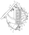
図1〜図6に拡大して示すように、上記空気調和装置Aはケース8を有する。このケース8には、空気導入口としての外気導入口28及び内気導入口29と、空気吹出口としてのデフロスタ口51、ベント口52、フロントヒート口57及びリアヒート口58とが開口されている。尚、これら外気導入口28、内気導入口29、デフロスタ口51、ベント口52、フロントヒート口57及びリアヒート口58の各々のケース8での開口位置は、本実施形態に記載の位置以外の位置に変更してもよいのは勿論である。   As shown in enlarged views in FIGS. 1 to 6, the air conditioner A has a case 8. The case 8 has an outside air inlet 28 and an inside air inlet 29 as air inlets, and a defroster port 51, a vent port 52, a front heat port 57 and a rear heat port 58 as air outlets. Note that the opening positions of the outside air introduction port 28, the inside air introduction port 29, the defroster port 51, the vent port 52, the front heat port 57, and the rear heat port 58 in the case 8 are positions other than the positions described in the present embodiment. Of course, it may be changed.

また、上記ケース8の内部には、上記外気導入口28及び内気導入口29(いずれも空気導入口)をデフロスタ口51、ベント口52、フロントヒート口57及びリアヒート口58(いずれも空気吹出口)に接続する空気通路12が設けられている(図6参照)。この空気通路12には、図6に示すように、外気導入口28または内気導入口29の一方から空気を空気通路12に吸い込んだ後にベント口52、フロントヒート口57、リアヒート口58及びデフロスタ口51の少なくとも1つから吹き出させる送風手段としてのブロワ23と、空気を冷却する冷却用熱交換器としてのエバポレータ37と、空気を加熱する加熱用熱交換器としてのヒータコア44と、上記エバポレータ37を経由した冷風及びヒータコア44を経由した温風の混合割合を変えてミックスチャンバ15に供給するミックス手段としてのミックスダンパ46と、開閉ダンパとしてのデフロスタダンパ61、ベントダンパ62及びヒートダンパ63とが配置されている。   Further, inside the case 8, the outside air introduction port 28 and the inside air introduction port 29 (both air introduction ports) are connected to a defroster port 51, a vent port 52, a front heat port 57 and a rear heat port 58 (both are air outlets). ) Is provided (see FIG. 6). As shown in FIG. 6, the air passage 12 has a vent port 52, a front heat port 57, a rear heat port 58, and a defroster port after air is sucked into the air passage 12 from one of the outside air introduction port 28 or the inside air introduction port 29. A blower 23 as a blowing means for blowing out from at least one of 51, an evaporator 37 as a cooling heat exchanger for cooling air, a heater core 44 as a heating heat exchanger for heating air, and the evaporator 37 A mix damper 46 as a mixing means for supplying the mix chamber 15 by changing the mixing ratio of the cold air passing through and the hot air passing through the heater core 44, and a defroster damper 61, a vent damper 62 and a heat damper 63 as opening and closing dampers are arranged. Yes.

上記ケース8は、図1〜図6及び図8に示すように、上部ケース9、下部ケース10、ヒータコアカバーダクト11及びインテークボックス27(内外気取り込み部)を一体的に組み付けてなる。上部ケース9下端の前半部及び後半部は、それぞれ互いに仕切られたダクト状の開口を形成しており、この上部ケース9下端の前半部(ダクト状開口の周縁部)は前側に向かうほど上側に位置するように傾斜している一方、後半部(ダクト状開口の周縁部)は略水平で前半部よりも上側に位置している(図8参照)。尚、前記図8に示すように、上部ケース9は左右中央部で左右に2分割された分割カバー9a,9a’からなり、また、ヒータコアカバーダクト11も同様に左右に2分割された分割カバー11a,11a’からなる。一方、上記インテークボックス27は、上下に2分割された分割カバー27a,27a’(上部カバー、下部カバー)からなる。   1 to 6 and 8, the case 8 is formed by integrally assembling an upper case 9, a lower case 10, a heater core cover duct 11, and an intake box 27 (inside / outside air intake portion). The front half and the rear half of the lower end of the upper case 9 form a duct-like opening that is partitioned from each other, and the front half of the lower end of the upper case 9 (the peripheral edge of the duct-like opening) is on the upper side toward the front side. While inclined so as to be positioned, the rear half (the peripheral edge of the duct-shaped opening) is substantially horizontal and located above the front half (see FIG. 8). As shown in FIG. 8, the upper case 9 is composed of divided covers 9a and 9a 'which are divided into left and right at the left and right central portions, and the heater core cover duct 11 is similarly divided into left and right divided covers. 11a, 11a ′. On the other hand, the intake box 27 is composed of divided covers 27a and 27a '(upper cover and lower cover) which are divided into two in the vertical direction.

上記下部ケース10は有底箱状のもので、その上端の前半部は上部ケース9下端の前半部と同様に前側に向かうほど上側に位置するように傾斜している一方、後半部は前半部よりも上側に段差状に突出していて該前半部と略平行に前上がりに傾斜している(図8参照)。   The lower case 10 has a bottomed box-like shape, and the front half of the upper end thereof is inclined so as to be located on the upper side toward the front side in the same manner as the front half of the lower end of the upper case 9, while the rear half is the front half. It protrudes in a step shape above the upper half and is inclined forward and substantially parallel to the front half (see FIG. 8).

そして、上記上部及び下部ケース9,10同士は、下部ケース10上端の前半部と上部ケース9下端の前半部とを気密状に接合することで一体的に組み付けられる。この組付状態では、上部ケース9下端の前半部と下部ケース10上端の前半部とがダクト状にシールされて接続され、その内部に空気通路12の一部が形成される。   The upper and lower cases 9, 10 are assembled together by joining the front half of the upper end of the lower case 10 and the front half of the lower end of the upper case 9 in an airtight manner. In this assembled state, the front half of the lower end of the upper case 9 and the front half of the upper end of the lower case 10 are sealed and connected in a duct shape, and a part of the air passage 12 is formed therein.

また、上部ケース9下端の後半部と下部ケース10上端の後半部との間には、ダクト装着部17が形成され、このダクト装着部17に上記ヒータコアカバーダクト11が装着されている。このヒータコアカバーダクト11は、上端及び下端が開口する断面矩形状のダクトからなり、その上端部を上記上部ケース9下端の後半部に、また下端部を下部ケース10上端の後半部にそれぞれ気密状に接合されている。   A duct mounting portion 17 is formed between the lower half of the lower end of the upper case 9 and the rear half of the upper end of the lower case 10, and the heater core cover duct 11 is mounted on the duct mounting portion 17. The heater core cover duct 11 is a duct having a rectangular cross section with an upper end and a lower end opened. The upper end of the heater core cover duct 11 is in the rear half of the lower end of the upper case 9, and the lower end is airtight in the rear half of the upper end of the lower case 10. It is joined to.

すなわち、図6に示すように、上記ヒータコアカバーダクト11を上部ケース9下端の後半部と下部ケース10上端の後半部との間のダクト装着部17に装着したときに、ヒータコアカバーダクト11の上端開口が上部ケース9下端の後半部の開口に、またヒータコアカバーダクト11の下端開口が下部ケース10上端の後半部の開口にそれぞれ気密状に連通して連続状のダクトをなし、その内部に空気通路12の一部たる後述の温風通路14が形成されるようになっている。   That is, as shown in FIG. 6, when the heater core cover duct 11 is mounted on a duct mounting portion 17 between the lower half of the lower end of the upper case 9 and the rear half of the upper end of the lower case 10, the upper end of the heater core cover duct 11 is The opening is connected to the opening in the rear half of the lower end of the upper case 9 and the opening of the lower end of the heater core cover duct 11 is airtightly connected to the opening in the rear half of the upper end of the lower case 10 to form a continuous duct. A hot air passage 14 which will be described later is formed as a part of the passage 12.

上記上部ケース9下端の後半部においてダクト装着部17の奥端部に相当する前端部には、上記円筒状のインパネメンバ6の略前半部を収容する断面円弧状の上部ケース側収容凹部18が形成されている。一方、ヒータコアカバーダクト11の前端部(嵌合方向の先端部)はダクト壁部をなすもので、この前端部にはインパネメンバ6の略後半部を収容する断面円弧状のカバーダクト側収容凹部19が形成されており、ヒータコアカバーダクト11をダクト装着部17に嵌合して装着したときに、両収容凹部18,19間にインパネメンバ6を挟み込んで固定し、その状態でケース8つまり空気調和装置Aがインパネメンバ6に支持されるようになっている。   An upper case-side receiving recess 18 having an arc-shaped cross-section for receiving a substantially front half of the cylindrical instrument panel member 6 is provided at the front end corresponding to the rear end of the duct mounting portion 17 in the lower half of the lower end of the upper case 9. Is formed. On the other hand, the front end portion (tip portion in the fitting direction) of the heater core cover duct 11 forms a duct wall portion, and the front end portion has an arc-shaped cover duct side accommodation recess that accommodates the substantially rear half portion of the instrument panel member 6. 19 is formed, and when the heater core cover duct 11 is fitted and mounted on the duct mounting portion 17, the instrument panel member 6 is sandwiched and fixed between the housing recesses 18 and 19, and in that state, the case 8 or air The harmony device A is supported by the instrument panel member 6.

尚、上記図8に示すように、上記ダクト装着部17の下端に相当する下部ケース10上端の後半部においてその左右側壁の上端部には前後方向に延びるガイドレール部20,20が形成されている一方、ヒータコアカバーダクト11下端の左右側部には上記ガイドレール部20,20に摺動可能に係合する係合部21,21が形成されており、この左右の係合部21,21と上記ガイドレール部20,20との係合により、ヒータコアカバーダクト11が前方向にスライドしながらダクト装着部17に装着される。   As shown in FIG. 8, guide rail portions 20, 20 extending in the front-rear direction are formed on the upper end portions of the left and right side walls in the rear half portion of the upper end of the lower case 10 corresponding to the lower end of the duct mounting portion 17. On the other hand, the left and right side portions of the lower end of the heater core cover duct 11 are formed with engaging portions 21 and 21 that are slidably engaged with the guide rail portions 20 and 20, respectively. The heater core cover duct 11 is mounted on the duct mounting portion 17 while sliding forward by the engagement between the guide rail portions 20 and 20.

上記上部ケース9には、図1〜図4にも示すように、その前側上部の左右中央に上部ケース9の一部をなす中空円筒状のファンハウジング22(このファンハウジング22も上部ケース9の一部であるので、左右に分割されている)が該上部ケース9の他の部分と一体に形成され、このファンハウジング22の内部には上記ブロワ23を構成するシロッコファンからなるブロワファン24(送風手段)が配置収容されている(図6参照)。そして、図8にも示すように、ファンハウジング22の左側壁(右側壁でもよい)にはモータ取付口22aが、また右側壁(左側壁でもよい)には吸込口22bが、さらに下側には吐出部22cがそれぞれ開口され、モータ取付口22aには上記ブロワ23を構成するブロワモータ25が左右方向に延びる出力軸(図示せず)をファンハウジング22内に臨ませて気密状に取付固定されている。このブロワモータ25の出力軸に上記ブロワファン24が回転一体に取付固定されている。   As shown in FIGS. 1 to 4, the upper case 9 has a hollow cylindrical fan housing 22 that forms a part of the upper case 9 at the center of the left and right front sides (this fan housing 22 is also included in the upper case 9). The blower fan 24 (which is a part of the sirocco fan constituting the blower 23) is formed integrally with the other parts of the upper case 9. The air blowing means is disposed and accommodated (see FIG. 6). As shown in FIG. 8, a motor mounting port 22a is provided on the left side wall (or the right side wall) of the fan housing 22, and a suction port 22b is further provided on the lower side (or the left side wall). Each of the discharge portions 22c is opened, and a blower motor 25 constituting the blower 23 is mounted and fixed in an airtight manner in the fan housing 22 with an output shaft (not shown) extending in the left-right direction facing the motor mounting port 22a. ing. The blower fan 24 is attached to and fixed to the output shaft of the blower motor 25 in an integrated manner.

一方、上記ファンハウジング22の吸込口22bには、該ハウジング22内方側に上記ブロワファン24の吸入口が位置付けられている一方、該ハウジング22外方側に詳しくは後述する上記インテークボックス27の下流端が気密状に接続されている(図8参照)。このインテークボックス27は図1に示すように中心線が左右方向に延びるように配置された概略有底円筒状のもので、開口端側が下流端とされてファンハウジング22の右側壁の吸込口22bに接続されている。   On the other hand, the suction port 22b of the fan housing 22 is provided with the suction port of the blower fan 24 on the inner side of the housing 22, while the intake box 27 described later in detail is provided on the outer side of the housing 22. The downstream end is connected in an airtight manner (see FIG. 8). As shown in FIG. 1, the intake box 27 has a substantially bottomed cylindrical shape arranged so that the center line extends in the left-right direction. The intake end 22 b on the right side wall of the fan housing 22 has an opening end side as a downstream end. It is connected to the.

上記インテークボックス27の詳しい構成については後述するが、図7にも示すように、該インテークボックス27の前側上部は、前側に向かうほど下側に傾斜するように形成されていて、その傾斜部分(第2外壁部)のほぼ全面に亘って略矩形状の外気導入口28が開口している。また、上記インテークボックス27の後側部分は、後側に向かうほど左右方向長さが短くなるように傾斜していて、その傾斜部分(第1壁部)のほぼ全面に亘って略矩形状の内気導入口29が開口している。そして、後述するように、上記インテークボックス27内に配設された内外気切換ダンパ34の位置を切り換えることによって外気導入口28若しくは内気導入口29から空気を導入するように構成されている。   Although the detailed configuration of the intake box 27 will be described later, as shown in FIG. 7, the front upper portion of the intake box 27 is formed so as to be inclined downward toward the front side. A substantially rectangular outside air inlet 28 opens over substantially the entire surface of the second outer wall portion. The rear portion of the intake box 27 is inclined so that the length in the left-right direction becomes shorter toward the rear side, and is substantially rectangular over substantially the entire inclined portion (first wall portion). The inside air inlet 29 is open. As will be described later, air is introduced from the outside air inlet 28 or the inside air inlet 29 by switching the position of the inside / outside air switching damper 34 disposed in the intake box 27.

ここで、上記内気導入口29は、インストルメントパネル1内で車室内に開放されている一方、外気導入口28は、フロントウィンドガラス前側の車体カウル部(図示せず)を経て車外に連通しており、外気導入口28により車外の空気(外気)を、また内気導入口29により車室内の空気(内気)をそれぞれケース8内の空気通路12に導入するようにしている。   Here, the inside air introduction port 29 is opened to the vehicle interior in the instrument panel 1, while the outside air introduction port 28 communicates with the outside of the vehicle through a vehicle body cowl portion (not shown) on the front windshield front side. The outside air introduction port 28 introduces air outside the vehicle (outside air) and the inside air introduction port 29 introduces air inside the vehicle interior (inside air) into the air passage 12 in the case 8.

図6に示すように、上記ファンハウジング22の吐出部22cは、後側に向かって斜め下方に延びる断面矩形状のダクトからなり、この吐出部22cの下流端部は、上部ケース9内下部の前端部と下部ケース10内の前端部とにより形成されるパワトラ収容部35に接続されている。このパワトラ収容部35は空気通路12の一部をなし、その下半部(下部ケース10内の部分)はファンハウジング22の吐出部22c下流端部から下側に拡がっている。   As shown in FIG. 6, the discharge part 22 c of the fan housing 22 is a duct having a rectangular cross section extending obliquely downward toward the rear side, and the downstream end of the discharge part 22 c is formed in the lower part of the upper case 9. It is connected to a powertra accommodating part 35 formed by the front end part and the front end part in the lower case 10. The powertra accommodating portion 35 forms a part of the air passage 12, and a lower half portion (a portion in the lower case 10) extends downward from the downstream end portion of the discharge portion 22 c of the fan housing 22.

そして、上記ファンハウジング22の吐出部22cの下流端部は、空気通路12の一部をなすエバポレータ収容部36に上記パワトラ収容部35を介して接続されている。このエバポレータ収容部36は、ファンハウジング22後側の斜め下側に位置していて、上部ケース9内下部の前部と下部ケース10内の前部とにより形成されており、上記エバポレータ37が空気通路12を横切るように配置されている。   The downstream end of the discharge part 22 c of the fan housing 22 is connected to the evaporator accommodating part 36 that forms a part of the air passage 12 via the powertra accommodating part 35. The evaporator accommodating portion 36 is located obliquely below the rear side of the fan housing 22 and is formed by a front portion in the lower portion of the upper case 9 and a front portion in the lower case 10. It arrange | positions so that the channel | path 12 may be crossed.

上記エバポレータ37は、チューブの周りに多数の伝熱フィンが伝熱可能に取り付けられたチューブアンドフィンタイプの略矩形板状の熱交換器で、チューブの両端にはそれぞれ接続配管37a,37aが接続されている。これにより、図外のコンプレッサにより圧縮された冷媒ガスを冷却して液冷媒にして、その液冷媒を減圧機構で減圧した後に上記エバポレータ37で蒸発させ、その蒸発潜熱によりブロワファン24からの空気と熱交換してそれを冷却し冷風を生成するようになっている。尚、エバポレータ37のチューブ内で液冷媒の蒸発がなくて蒸発潜熱が発生しない状態では、エバポレータ37に流入した空気は冷却されずに流入温度のままでエバポレータ37から出るが、本実施形態では、その場合でもエバポレータ37から出た空気を冷風とする。   The evaporator 37 is a tube-and-fin type heat exchanger having a substantially rectangular plate shape in which a large number of heat transfer fins are attached around the tube so that heat can be transferred. Connection pipes 37a and 37a are connected to both ends of the tube, respectively. Has been. As a result, the refrigerant gas compressed by the compressor (not shown) is cooled to form a liquid refrigerant, and the liquid refrigerant is decompressed by the decompression mechanism and then evaporated by the evaporator 37. The latent heat of vaporization causes the air from the blower fan 24 to Heat is exchanged to cool it and generate cold air. In the state where there is no evaporation of the liquid refrigerant in the tube of the evaporator 37 and no latent heat of evaporation is generated, the air flowing into the evaporator 37 is not cooled and leaves the evaporator 37 at the inflow temperature, but in this embodiment, Even in such a case, the air emitted from the evaporator 37 is cold air.

また、上記ファンハウジング22の吐出部22c下流端部とエバポレータ収容部36との間には、エバポレータ37の直上流側を覆って該エバポレータ37に流入する空気を濾過するフィルタ機構38が配設されている。また、このフィルタ機構38の上流側、つまりパワトラ収容部35の下半部において下部ケース10の右側壁(左側壁でもよい)には放熱用パワトラ39がパワトラ収容部35内に臨むように取り付けられている。なお、この放熱用パワトラ39は、上記ブロワモータ25への印加電圧を制御するブロワモータ印加電圧制御用トランジスタ(図示せず)を冷却するためのものである。   A filter mechanism 38 is provided between the downstream end of the discharge portion 22c of the fan housing 22 and the evaporator accommodating portion 36 so as to cover the immediately upstream side of the evaporator 37 and to filter the air flowing into the evaporator 37. ing. Further, on the upstream side of the filter mechanism 38, that is, in the lower half of the powertra housing portion 35, a heat dissipating powertra 39 is attached to the right side wall (or the left side wall) of the lower case 10 so as to face the powertra housing portion 35. ing. The heat dissipating power transformer 39 is for cooling a blower motor application voltage control transistor (not shown) for controlling the voltage applied to the blower motor 25.

上記エバポレータ37下流側の空気通路12は、冷風通路13と温風通路14とに分岐されている。上記冷風通路13は、エバポレータ37下流側(後側)の略上半部から上記カバーダクト側収容凹部19前側を通って略上側に延びるダクト内に形成されるもので、この冷風通路13により、エバポレータ37を経由した冷風の一部ないし全部を直接流すようにしている。   The air passage 12 on the downstream side of the evaporator 37 is branched into a cold air passage 13 and a hot air passage 14. The cold air passage 13 is formed in a duct extending from the substantially upper half of the evaporator 37 downstream side (rear side) to the upper side through the front side of the cover duct side accommodating recess 19. A part or all of the cold air passing through the evaporator 37 is directly flowed.

一方、上記温風通路14は、エバポレータ37下流側の略下半部から後方に延びた後に上側に向かい、上記下部ケース10上端の後半部(ダクト装着部17下端)の開口と、この開口に下端開口にて連通するヒータコアカバーダクト11内と、このヒータコアカバーダクト11の上端開口に連通する上部ケース9下端の後半部(ダクト装着部17上端)の開口とを結ぶように前側且つ斜め上側に延びている。この温風通路14の途中において上記下部ケース10上端の後半部には温風通路14(空気通路12)の一部をなすヒータコア収容部43が形成され、このヒータコア収容部43内に上記ヒータコア44が温風通路14を横切るように配置されている。すなわち、ヒータコア44は、図6に示すように、上記エバポレータ37の下流側に略水平方向に配置されている。このヒータコア44も、上記エバポレータ37と同様に、チューブの周りに多数の伝熱フィンが取り付けられたタイプの熱交換器であり、チューブの両端は接続配管44a,44a(図1及び図2参照)を介して車載エンジンのウォータジャケット(冷却水通路)に接続されており、エンジンの冷却により昇温した冷却水をヒータコア44に流すことにより、エバポレータ37を経由して冷却された冷風の一部ないし全部と熱交換してそれを加熱し温風を生成し、この温風を温風通路14に流すようにしている。尚、ヒータコア44のチューブに高温度の冷却水が流れないときには、ヒータコア44に流入した空気は加熱されずに流入温度のままでヒータコア44から出るが、本実施形態では、その場合もヒータコア44から出た空気を温風とする。   On the other hand, the hot air passage 14 extends rearward from a substantially lower half portion on the downstream side of the evaporator 37 and then moves upward, and opens in the latter half portion (lower end of the duct mounting portion 17) of the lower case 10 and the opening. In the heater core cover duct 11 that communicates with the lower end opening and the upper half of the upper case 9 that communicates with the upper end opening of the heater core cover duct 11 and the opening of the rear half (the upper end of the duct mounting portion 17). It extends. In the middle of the hot air passage 14, a heater core housing portion 43 that forms a part of the hot air passage 14 (air passage 12) is formed in the rear half of the upper end of the lower case 10, and the heater core 44 is formed in the heater core housing portion 43. Is arranged so as to cross the hot air passage 14. That is, as shown in FIG. 6, the heater core 44 is disposed in a substantially horizontal direction on the downstream side of the evaporator 37. Similarly to the evaporator 37, the heater core 44 is a type of heat exchanger in which a large number of heat transfer fins are attached around the tube, and both ends of the tube are connected pipes 44a and 44a (see FIGS. 1 and 2). Is connected to the water jacket (cooling water passage) of the in-vehicle engine, and the cooling water heated by the cooling of the engine is caused to flow to the heater core 44, whereby a part of the cold air cooled via the evaporator 37 or All the heat is exchanged and heated to generate hot air, and this hot air flows through the hot air passage 14. When high-temperature cooling water does not flow through the tube of the heater core 44, the air that has flowed into the heater core 44 is not heated and exits the heater core 44 at the inflow temperature. Let the air that comes out be warm air.

尚、上記図8に示すように、下部ケース10の後半部の右側壁(左側壁でもよい)には装着口45が形成されており、この装着口45を通してヒータコア44がヒータコア装着部43に装着される。そして、このヒータコア44の装着状態では、装着口45はヒータコア44自体により気密状に閉塞され、この装着口45において接続配管44a,44aが下部ケース10(ケース8)外に位置するようになっている。   As shown in FIG. 8, a mounting port 45 is formed in the right side wall (or the left side wall) of the rear half of the lower case 10, and the heater core 44 is mounted on the heater core mounting portion 43 through the mounting port 45. Is done. When the heater core 44 is mounted, the mounting port 45 is hermetically closed by the heater core 44 itself, and the connection pipes 44a and 44a are located outside the lower case 10 (case 8) in the mounting port 45. Yes.

上記冷風通路13の下流端(上端)と温風通路14の下流端(上端)とは互いにミックスチャンバ15(温調室)で連通している(ミックスチャンバ15において実質的に冷風と温風とを混合して温調風を生成している部分を図6で一点鎖線にて示す)。このミックスチャンバ15は空気通路12の一部を構成しており、このミックスチャンバ15において冷風及び温風を混合させ、温調風を生成する。ミックスチャンバ15と冷風通路13及び温風通路14の各下流端との間には、冷風通路13からの冷風と温風通路14からの温風との混合割合を変えて温調風の温度を変更する上記ミックスダンパ46が設けられている。このミックスダンパ46は、冷風通路13及び温風通路14の各下流端間の近傍に位置し左右方向に延びる支持軸46a回りに揺動する2つの冷風及び温風ダンパ部46b,46cを備えたバタフライタイプのもので、該両ダンパ部46b,46cは支持軸46aに対してその下方に180°よりも小さい所定の角度(例えば125°)をなすように交差している。   The downstream end (upper end) of the cold air passage 13 and the downstream end (upper end) of the hot air passage 14 are communicated with each other in the mix chamber 15 (temperature control chamber). The part which mixes these and has produced | generated the temperature control wind is shown with the dashed-dotted line in FIG. The mix chamber 15 constitutes a part of the air passage 12, and cool air and hot air are mixed in the mix chamber 15 to generate temperature-controlled air. Between the mix chamber 15 and each downstream end of the cold air passage 13 and the hot air passage 14, the mixing ratio of the cold air from the cold air passage 13 and the hot air from the hot air passage 14 is changed to adjust the temperature of the temperature-controlled air. The mix damper 46 to be changed is provided. The mix damper 46 includes two cold air and hot air damper portions 46b and 46c that swing around a support shaft 46a that is positioned between the downstream ends of the cold air passage 13 and the hot air passage 14 and extends in the left-right direction. This is a butterfly type, and both the damper portions 46b and 46c intersect with the support shaft 46a so as to form a predetermined angle (for example, 125 °) smaller than 180 ° below the support shaft 46a.

上記冷風ダンパ部46bは、冷風通路13の下流端を、また上記温風ダンパ部46cは温風通路14の下流端をそれぞれ開閉するようになっており、冷風通路13側にある冷風ダンパ部46bが冷風通路13下流端を全閉状態にしてミックスチャンバ15との連通を遮断したときには、温風通路14側にある温風ダンパ部46cが温風通路14下流端を全開状態にしてミックスチャンバ15と連通させる一方、上記冷風ダンパ部46bが冷風通路13下流端を全開状態にしてミックスチャンバ15と連通させたときには、温風ダンパ部46cが温風通路14下流端を全閉状態にしてミックスチャンバ15との連通を遮断する。そして、これら2つの位置の中間位置では、冷風通路13及び温風通路14の各開度を逆方向に相対的に変えて、ミックスチャンバ15に流入する冷風及び温風の各流量を変更し、ミックスチャンバ15において冷風及び温風の混合割合を変えて温調風の温度を変更調整するようになっている。   The cold air damper portion 46b opens and closes the downstream end of the cold air passage 13, and the hot air damper portion 46c opens and closes the downstream end of the hot air passage 14, respectively, and the cold air damper portion 46b on the cold air passage 13 side. When the downstream end of the cold air passage 13 is fully closed and the communication with the mix chamber 15 is shut off, the hot air damper portion 46c on the hot air passage 14 side fully opens the downstream end of the hot air passage 14 and the mix chamber 15 On the other hand, when the cold air damper portion 46b communicates with the mix chamber 15 with the downstream end of the cold air passage 13 fully opened, the hot air damper portion 46c fully closes the downstream end of the hot air passage 14 with the mix chamber. Block communication with 15. And at the intermediate position between these two positions, the respective openings of the cold air passage 13 and the hot air passage 14 are relatively changed in the opposite directions, and the respective flow rates of the cold air and the hot air flowing into the mix chamber 15 are changed, In the mix chamber 15, the temperature of the temperature-controlled air is changed and adjusted by changing the mixing ratio of the cold air and the hot air.

上記ミックスダンパ46の支持軸46aは上部ケース9の右側壁(左側壁でもよい)から該上部ケース9外に突出していて、この突出部には図外の電動アクチュエータが駆動連結されており、この電動アクチュエータによりミックスダンパ46を空調モードに合わせて開閉制御するようにしている。   The support shaft 46a of the mix damper 46 protrudes from the right side wall (or the left side wall) of the upper case 9 to the outside of the upper case 9, and an electric actuator (not shown) is drivingly connected to the protruding portion. The electric damper controls the opening and closing of the mix damper 46 in accordance with the air conditioning mode.

上記ミックスダンパ46の支持軸46a真下には、上部ケース9の一部を構成し且つ上記冷風通路13及び温風通路14を仕切る隔壁9eの上端部(下流端部)が位置し、この隔壁9eの上端部には、その左右幅の全体に亘り調整手段としての調整リブ48が先端(上端)を支持軸46a下側に近接させた状態で突設されており、この調整リブ48により支持軸46aとその下側の上部ケース9内面との間の隙間の大きさを調整するようにしている。このような構成にすることで、例えば空調モードがコールドモードとフルホットモードとの間で切り換わったときの温度変化をスムーズに変化させることが可能になる。   Immediately below the support shaft 46a of the mix damper 46 is located an upper end portion (downstream end portion) of a partition wall 9e that constitutes a part of the upper case 9 and partitions the cool air passage 13 and the hot air passage 14, and this partition wall 9e. An adjustment rib 48 as an adjustment means is projected from the upper end of the left and right widths with the tip (upper end) being close to the lower side of the support shaft 46a. The adjustment rib 48 supports the support shaft. The size of the gap between 46a and the inner surface of the lower upper case 9 is adjusted. By adopting such a configuration, for example, it is possible to smoothly change the temperature change when the air-conditioning mode is switched between the cold mode and the full hot mode.

図1にも示すように、上記ファンハウジング22後側の上部ケース9の上面には前側に上記デフロスタ口51が、またそのさらに後側には上記ベント口52が前後に並んで開口していて、これらデフロスタ口51及びベント口52は上部ケース9の隔壁9bにより連通不能に区画されている。上記デフロスタ口51は図外のデフロスタダクトを介して上記インストルメントパネル1のデフロスタ吹出しノズル4,4に、またベント口52は図外のベントダクトを介してインストルメントパネル1のセンタ吹出しノズル2及び左右のサイド吹出しノズル3,3にそれぞれ接続されている。   As shown in FIG. 1, the upper surface of the upper case 9 on the rear side of the fan housing 22 has the defroster port 51 on the front side, and the vent port 52 on the rear side. The defroster port 51 and the vent port 52 are partitioned by the partition wall 9b of the upper case 9 so as not to communicate. The defroster port 51 is connected to the defroster outlet nozzles 4 and 4 of the instrument panel 1 through a defroster duct (not shown), and the vent port 52 is connected to the center outlet nozzle 2 of the instrument panel 1 and the vent port (not shown). The left and right side blowing nozzles 3 and 3 are connected respectively.

また、上部ケース9の上側後部にはヒートダクト部54が一体に形成されている。このヒートダクト部54は、図5にも示すように、上部ケース9の上側後部から後方に向かって斜め下方に延びる角筒状のダクト本体54aと、このダクト本体54aの後部左右側壁から左右方向に突出する1対のフロント分岐ダクト部54b,54bと、ダクト本体54aの後壁左右中央部から後方に向かって斜め下方にダクト本体54aを延長するように突出するリア分岐ダクト部54cとを備えてなり、これらダクト本体54a、フロント分岐ダクト部54b,54b及びリア分岐ダクト部54c内にヒート通路55が形成され(図6参照)、このヒート通路55の上流端は上記ミックスチャンバ15に対し、温風通路14下流端の後側で、つまり冷風通路13の下流端よりも温風通路14の下流端に近い側で該両下流端と前後方向に略直列に並ぶように配置されて連通されている。   A heat duct portion 54 is integrally formed on the upper rear portion of the upper case 9. As shown in FIG. 5, the heat duct portion 54 includes a rectangular tube-shaped duct main body 54a extending obliquely downward from the upper rear portion of the upper case 9 and the left and right side walls of the rear portion of the duct main body 54a. A pair of front branch duct portions 54b and 54b projecting to the rear, and a rear branch duct portion 54c projecting so as to extend the duct body 54a obliquely downward from the left and right central portion of the rear wall of the duct body 54a. A heat passage 55 is formed in the duct main body 54a, the front branch duct portions 54b and 54b and the rear branch duct portion 54c (see FIG. 6), and the upstream end of the heat passage 55 is connected to the mix chamber 15. On the rear side of the downstream end of the hot air passage 14, that is, on the side closer to the downstream end of the hot air passage 14 than the downstream end of the cold air passage 13, in the front-rear direction. Are arranged so as to line up in series are communicated.

また、上記両フロント分岐ダクト部54b,54bのそれぞれの先端には上記フロントヒート口57,57が、またリア分岐ダクト部54cの先端には上記リアヒート口58がそれぞれ開口している。これにより、ヒート通路55の下流側部は、フロント分岐ダクト部54b,54b及びリア分岐ダクト部54cの3つに分岐されて上記フロントヒート口57,57及びリアヒート口58に連通し、そのうち、リア分岐ダクト部54c内に形成される、リアヒート口58への分岐通路55dは、該分岐通路55d上流側のヒート通路55を下流側に延長するように延びている。そして、車両の左側又は右側側方から見て、リア分岐ダクト部54cのダクト本体54aからの分岐位置(開口位置)は、両フロント分岐ダクト部54b,54bの同分岐位置に比べミックスチャンバ15から離れた後側に位置している。尚、55cはフロント分岐ダクト部54b内に形成されたヒート通路55の分岐通路である。   The front heat ports 57 and 57 are opened at the front ends of the front branch duct portions 54b and 54b, and the rear heat port 58 is opened at the front end of the rear branch duct portion 54c. Thereby, the downstream side portion of the heat passage 55 is branched into three parts, that is, the front branch duct portions 54b and 54b and the rear branch duct portion 54c, and communicates with the front heat ports 57 and 57 and the rear heat port 58. A branch passage 55d formed in the branch duct portion 54c and extending to the rear heat port 58 extends so as to extend the heat passage 55 upstream of the branch passage 55d to the downstream side. When viewed from the left or right side of the vehicle, the branch position (opening position) of the rear branch duct portion 54c from the duct body 54a is from the mix chamber 15 as compared to the same branch position of both the front branch duct portions 54b and 54b. Located on the back side away. Reference numeral 55c denotes a branch passage of the heat passage 55 formed in the front branch duct portion 54b.

上記各フロントヒート口57には、下流端がインストルメントパネル1下部の車室内(前席に着座した乗員の足元部分)まで延びる図外のフロントヒートダクトの上流端が、またリアヒート口58には、下流端が車室内の後席まで延びる図外のリアヒートダクトの上流端がそれぞれ接続されている。これにより、各フロントヒート口57から温風を吹き出させて、それをフロントヒートダクトを介して前席に着座した乗員の足元に送給する一方、リアヒート口58からも温風を吹き出させて、それをリアヒートダクトを介して後席に着座した乗員の足元に送給することができる。   Each front heat port 57 has an upstream end of a front heat duct (not shown) whose downstream end extends to the passenger compartment at the lower part of the instrument panel 1 (the feet of the passenger seated in the front seat). The upstream ends of the rear heat ducts (not shown) whose downstream ends extend to the rear seats of the passenger compartment are connected to each other. As a result, hot air is blown out from each front heat port 57, and it is sent to the feet of the occupants seated in the front seat via the front heat duct, while hot air is blown out from the rear heat port 58, It can be fed to the feet of the occupant seated in the rear seat via the rear heat duct.

上記ミックスチャンバ15は、上記フロントヒート口57及びリアヒート口58と連通しているだけでなく、上記デフロスタ口51及びベント口52とも連通している。このミックスチャンバ15とデフロスタ口51との間には該デフロスタ口51を開閉するためのデフロスタダンパ61が、またミックスチャンバ15とベント口52との間には該ベント口52を開閉するためのベントダンパ62が、さらにミックスチャンバ15とフロントヒート口57及びリアヒート口58との間には該両ヒート口57,58を開閉するためのヒートダンパ63がそれぞれ配置されている。すなわち、ヒートダンパ63は、ヒートダクト部54においてダクト本体54aのフロント分岐ダクト部54b,54b及びリア分岐ダクト部54cへの分岐位置(フロント及びリアヒート口57,58への分岐位置)よりも上流側のヒート通路55、つまりヒート通路55の上流端(ミックスチャンバ15との境界部)を開閉するようになっている。尚、これに代え、ヒートダンパ63をヒート通路55の上流端よりも下流側に配置してその部分を開閉するようにしてもよい。   The mix chamber 15 not only communicates with the front heat port 57 and the rear heat port 58 but also communicates with the defroster port 51 and the vent port 52. A defroster damper 61 for opening and closing the defroster port 51 is provided between the mix chamber 15 and the defroster port 51, and a vent damper for opening and closing the vent port 52 between the mix chamber 15 and the vent port 52. 62, and between the mix chamber 15 and the front heat port 57 and the rear heat port 58, heat dampers 63 for opening and closing the heat ports 57 and 58 are respectively disposed. That is, the heat damper 63 is located upstream of the branch position of the duct body 54a to the front branch duct portions 54b and 54b and the rear branch duct portion 54c (branch position to the front and rear heat ports 57 and 58) in the heat duct portion 54a. The heat passage 55, that is, the upstream end of the heat passage 55 (the boundary with the mix chamber 15) is opened and closed. Instead of this, the heat damper 63 may be arranged on the downstream side of the upstream end of the heat passage 55 so as to open and close the portion.

これらデフロスタダンパ61、ベントダンパ62及びヒートダンパ63は、いずれも左右方向に延びる支持軸61a〜63a回りに揺動する2つのダンパ部を備えたバタフライ型のもので、両ダンパ部は支持軸61a〜63aに対して略180°の角度をなすように交差しており、その回動によりデフロスタ口51、ベント口52、フロントヒート口57及びリアヒート口58の各開度を変えるようにしている。そして、デフロスタダンパ61、ベントダンパ62及びヒートダンパ63の各支持軸61a〜63aは上部ケース9の左側壁(右側壁でもよい)から上部ケース9外に突出していて、この突出部には、カム及びリンクからなる連動機構65を介して電動アクチュエータ66が連結されており(図3参照)、この電動アクチュエータ66により各ダンパ61〜63を空調モードに合わせて連係させながら開閉制御するようにしている。   The defroster damper 61, the vent damper 62, and the heat damper 63 are all of a butterfly type having two damper portions that swing around support shafts 61a to 63a extending in the left-right direction, and both damper portions are support shafts 61a to 63a. The opening of the defroster port 51, the vent port 52, the front heat port 57, and the rear heat port 58 is changed by the rotation. The support shafts 61 a to 63 a of the defroster damper 61, the vent damper 62, and the heat damper 63 protrude from the left side wall (or right side wall) of the upper case 9 to the outside of the upper case 9. An electric actuator 66 is connected via an interlock mechanism 65 (see FIG. 3), and the electric actuator 66 controls the opening and closing of the dampers 61 to 63 in association with the air conditioning mode.

図2〜図6に示すように、上記ヒータコア44の略下側に位置するケース8の底部、つまり下部ケース10の底部は、上側に向かってテーパ状に拡開する断面形状とされている。すなわち、この下部ケース10底部の前側部10a(一側部)は、上記エバポレータ37側つまり前側に向かうほど上側に位置付けられるように水平面に対し所定の傾斜角度で傾斜し、上記エバポレータ収容部36の下部を経てパワトラ収容部35の下部まで滑らかに連続している。一方、下部ケース10底部の後側部10b(他側部)は、ヒータコア44側つまり後側に向かうほど上側に位置付けられるように水平面に対し所定の傾斜角度で傾斜している。この下部ケース10の底部において前側部10a及び後側部10bの境界部分(テーパ形状の先端部)が最下端部10cとなっている。そして、この下部ケース10底部の最下端部10cは右側(左側であってもよい)に向かうほど下方に傾斜し、その右側壁部に、エバポレータ37にて発生した凝縮水を排水させるためのドレン口68が設けられている。なお、上記図2〜6において、69はドレン口68に接続されたドレンホースである。   As shown in FIGS. 2 to 6, the bottom portion of the case 8 positioned substantially below the heater core 44, that is, the bottom portion of the lower case 10 has a cross-sectional shape that expands in a tapered shape toward the upper side. That is, the front side portion 10a (one side portion) at the bottom of the lower case 10 is inclined at a predetermined inclination angle with respect to the horizontal plane so that the front side portion 10a (one side portion) is positioned on the evaporator 37 side, that is, the front side. It continues smoothly through the lower part to the lower part of the powertra accommodating part 35. On the other hand, the rear side portion 10b (other side portion) of the bottom portion of the lower case 10 is inclined at a predetermined inclination angle with respect to the horizontal plane so as to be positioned on the heater core 44 side, that is, toward the rear side. In the bottom portion of the lower case 10, a boundary portion (tapered tip portion) between the front side portion 10a and the rear side portion 10b is a lowermost end portion 10c. The lowermost end 10c of the bottom of the lower case 10 is inclined downward toward the right side (may be the left side), and the drain for draining the condensed water generated by the evaporator 37 to the right side wall. A mouth 68 is provided. 2 to 6, 69 is a drain hose connected to the drain port 68.

さらに、上記図6に示すように、上部ケース9内のミックスチャンバ15には、上記ミックスダンパ46が温風通路14を開状態にしているときに、その温風通路14の出口部から出た温風の一部を、上記デフロスタ口51近傍のミックスチャンバ15前端部周辺にバイパスして供給する左右1対の温風バイパス通路71,71が形成されている。この温風バイパス通路71,71を介して、温風通路14の下流端から出た温風の一部をデフロスタダンパ61の略真下位置まで導くことで、そのバイパスされた温風がデフロスタ口51から吹き出すため、デフロスタ性能を高めることができる。   Further, as shown in FIG. 6, the mix damper 46 in the upper case 9 exits from the outlet of the hot air passage 14 when the mix damper 46 is in the open state. A pair of left and right hot air bypass passages 71 and 71 for supplying a part of the hot air by bypassing the vicinity of the front end of the mix chamber 15 near the defroster port 51 are formed. By guiding a part of the warm air coming out from the downstream end of the warm air passage 14 to the position just below the defroster damper 61 via the warm air bypass passages 71, 71, the bypassed warm air is defrosted by the defroster port 51. Since it blows out from, it can improve defroster performance.

具体的には、図10にも示すように、上部ケース9において上記ミックスチャンバ15近くの左右側壁には、上記温風通路14の下流端近傍からデフロスタダンパ61の略真下位置までの範囲に亘り、左右方向外側に折れ曲がった段部9cが形成され、この段部9c上側の上部ケース9側壁内面には、該段部9cとの間に溝部が形成されるようにリブ9dが水平方向に突出している。そして、この段部9cとリブ9dとの間の溝部は、上部ケース9とは別体のガイドプレート72により閉断面空間を形成するように覆われて、この閉断面空間が上述の各温風バイパス通路71を構成するようになっている。なお、この各温風バイパス通路71の上流端は、温風通路14の下流端近傍に、下流端はデフロスタダンパ61の略真下位置に、それぞれ開口している。   Specifically, as shown in FIG. 10, the left and right side walls near the mix chamber 15 in the upper case 9 extend from the vicinity of the downstream end of the hot air passage 14 to the position just below the defroster damper 61. A step portion 9c that is bent outward in the left-right direction is formed, and a rib 9d protrudes in the horizontal direction so that a groove is formed between the step portion 9c and the inner surface of the side wall of the upper case 9 above the step portion 9c. ing. The groove between the step 9c and the rib 9d is covered with a guide plate 72 separate from the upper case 9 so as to form a closed cross-sectional space. A bypass passage 71 is configured. The upstream end of each warm air bypass passage 71 is opened in the vicinity of the downstream end of the warm air passage 14, and the downstream end is opened at a position almost directly below the defroster damper 61.

このように、各温風バイパス通路71をケース8内に設けることで、その温風バイパス通路をケース8外に形成する場合のように、空気調和装置Aにおけるケース8外の他の部品や車両の部品との干渉等を考慮せずとも済み、ケース8外のスペースを有効に確保することができる。   Thus, by providing each warm air bypass passage 71 in the case 8, other parts outside the case 8 in the air conditioner A and the vehicle as in the case where the warm air bypass passage is formed outside the case 8. It is not necessary to consider interference with other parts, and the space outside the case 8 can be effectively secured.

なお、上記ガイドプレート72は、その周縁部のブラケットを貫通する取付ねじ72bを上部ケース9の側壁(詳しくはそのボス部)に螺合締結することで、上部ケース9の側壁に取付固定されている。   The guide plate 72 is fixedly attached to the side wall of the upper case 9 by screwing and fastening an attachment screw 72b penetrating the peripheral edge bracket to the side wall of the upper case 9 (specifically, its boss). Yes.

上記各ガイドプレート72において温風バイパス通路71の下流端部に位置する部分には、相対する上部ケース9の左右側壁に向かって延びるガイド部72aがそれぞれ一体形成されていて、これら両ガイドプレート72,72のガイド部72a,72a先端同士は上部ケース9の左右略中央位置で一体的に接合(単なる当接でもよく、或いは若干の間隙をあけて離隔していてもよい)されている。つまり、これら両ガイド部72a,72aは、上記各ガイドプレート71において温風バイパス通路71の下流端に位置する部分にミックスチャンバ15の幅方向(左右方向)の全体に延びるように形成されている。   Guide portions 72 a extending toward the left and right side walls of the opposing upper case 9 are integrally formed at a portion of each guide plate 72 positioned at the downstream end of the hot air bypass passage 71. 72, the tips of the guide portions 72a and 72a are joined together at substantially the center position on the left and right sides of the upper case 9 (simply contact or may be separated by a slight gap). That is, both the guide portions 72a and 72a are formed so as to extend in the width direction (left-right direction) of the mix chamber 15 at a portion of each guide plate 71 located at the downstream end of the warm air bypass passage 71. .

また、上記両ガイド部72a,72aにより、ミックスチャンバ15の前端部(一部)つまり冷風通路13の出口側に、デフロスタ口51(上側)に向かって開放された出口室16が区画されて形成され、この出口室16に各温風バイパス通路71の下流端が開口している。これにより、温風通路14の下流端から出た温風の一部を上部ケース9の左右側部にて2つの温風バイパス通路71,71に導入し、この温風を略ミックスチャンバ15の大半部をバイパスさせながらデフロスタダンパ61の略真下位置まで導いて、ガイドプレート72,72のガイド部72a,72aによりケース8の左右の全体に亘り略均等に吹き出させることができる。   The guide chambers 72a and 72a form an outlet chamber 16 opened toward the defroster port 51 (upper side) at the front end (part) of the mix chamber 15, that is, the outlet side of the cool air passage 13. The downstream ends of the hot air bypass passages 71 are opened in the outlet chamber 16. Thereby, a part of the warm air coming out from the downstream end of the warm air passage 14 is introduced into the two warm air bypass passages 71, 71 at the left and right sides of the upper case 9, and this warm air is supplied to the substantially mixed chamber 15. It can be guided to the position almost directly below the defroster damper 61 while bypassing most of the parts, and can be blown out substantially evenly across the left and right sides of the case 8 by the guide portions 72a and 72a of the guide plates 72 and 72.

さらに、このように温風をケース8の左右の全体に亘り略均等に吹き出させる特性の他に、例えば両ガイドプレート72,72のガイド部72a,72a等により温風バイパス通路71の出口部の構造や形状を変えたり、温風バイパス通路71の断面積等を変えたりすることで、ガイドされる温風の風量、風速、風向等を変更して、その吹出しのバリエーションを広げることもできる。例えば、ケース8の左右中央部での温風吹出し量を左右側部よりも多くしたり、或いは逆に、ケース8の左右側部での温風吹出し量を左右中央部よりも多くしたり、さらには、ケース8の左右中央部及び左右側部での温風吹出し量を両者の中間部よりも多くしたりすることができる。これらは必要に応じて適宜選択すればよい。   Further, in addition to the characteristic that the hot air is blown out almost uniformly over the entire left and right sides of the case 8 as described above, for example, the guide portions 72a and 72a of the both guide plates 72 and 72 are provided at the outlet of the hot air bypass passage 71. By changing the structure and shape, changing the cross-sectional area of the hot air bypass passage 71, and the like, it is possible to change the air volume, the wind speed, the wind direction, and the like of the guided hot air, and to widen the variation of the blowing. For example, the amount of hot air blown out at the left and right central part of the case 8 is larger than the left and right side parts, or conversely, the amount of hot air blown out at the left and right side parts of the case 8 is larger than that of the left and right central part, Further, it is possible to increase the amount of hot air blown out at the left and right central portions and the left and right side portions of the case 8 as compared with the intermediate portion between them. What is necessary is just to select these suitably as needed.

また、上述のように、各温風バイパス通路71を、上部ケース9の段部9c及びリブ9dとガイドプレート72とにより区画形成することで、上部ケース9の他にガイドプレート72を設けるだけで温風バイパス通路71を形成することができ、その形成が容易であり、温風バイパス通路71の構造も簡単になる。   Further, as described above, each hot air bypass passage 71 is partitioned by the step 9c and rib 9d of the upper case 9 and the guide plate 72, so that only the guide plate 72 is provided in addition to the upper case 9. The hot air bypass passage 71 can be formed, the formation thereof is easy, and the structure of the hot air bypass passage 71 is also simplified.

なお、この実施形態では、上部ケース9の壁部に段部9c及びリブ9dを形成し、これらをガイドプレート72で覆って閉断面空間の温風バイパス通路71を形成しているが、この他、壁部に1対のリブを互いに平行に突設し、これらをガイドプレートにより覆うか、或いは壁部全体に凹溝を形成して、その開口をガイドプレートで覆うかすることにより、閉断面空間の温風バイパス通路を形成してもよい。   In this embodiment, the step portion 9c and the rib 9d are formed on the wall portion of the upper case 9, and these are covered with the guide plate 72 to form the hot air bypass passage 71 in the closed section space. A closed cross section can be formed by projecting a pair of ribs on the wall in parallel with each other and covering them with a guide plate, or by forming a groove on the entire wall and covering the opening with the guide plate. A hot air bypass passage in the space may be formed.

また、上記各温風バイパス通路71は、ケース8内のミックスチャンバ15において上部ケース9の段部9c及びリブ9dとガイドプレート72とによって区画される閉断面空間で構成されているので、仮に、この各温風バイパス通路71を流れる温風が通路71外に漏れ出たとしても、その漏出した温風はミックスチャンバ15に流入するだけでケース8外に出ることはない。このため、同様の温風バイパス通路をケース8外に形成する場合では、その温風バイパス通路から温風が漏出するのを避けるために各種取付ねじの締結やシール構造を精度よく行っておく必要があるが、それに比べ、温風バイパス通路71の漏れ防止用のシール構造等を簡略化でき、部品点数の低減等を図ることができる。   Moreover, since each said warm air bypass channel | path 71 is comprised by the closed cross-sectional space divided by the step part 9c and rib 9d of the upper case 9, and the guide plate 72 in the mix chamber 15 in the case 8, temporarily, Even if the hot air flowing through each hot air bypass passage 71 leaks out of the passage 71, the leaked hot air flows into the mix chamber 15 and does not go out of the case 8. For this reason, when a similar hot air bypass passage is formed outside the case 8, it is necessary to perform fastening of various mounting screws and a sealing structure with high accuracy in order to avoid leakage of hot air from the hot air bypass passage. However, compared with that, the seal structure for preventing leakage of the hot air bypass passage 71 can be simplified, and the number of parts can be reduced.

さらに、上記両ガイドプレート72,72のガイド部72a,72aにより、ミックスチャンバ15の前端部に、デフロスタ口51側(上側)に開放された形状の出口室16がミックスチャンバ15の他の部分(大半部)と区画されて形成されているので、この出口室16は、冷風通路13の出口部や上記ミックスチャンバ15の大半部(前端部を除く部分)に対しガイド部72aによって遮断された構造になる。そして、この出口室16に各温風バイパス通路71の下流端が開口しているので、この温風バイパス通路71から出口室16に吐出された温風は、上記ミックスチャンバ15の大半部にある温調風、特に冷風通路13から出た冷風の流れの影響を受け難くなる。このことで、そのバイパスされた温風を安定して吐出させることができる。   Furthermore, the outlet chamber 16 having a shape opened to the front side of the defroster port 51 (upper side) is provided at the other end of the mix chamber 15 by the guide portions 72a and 72a of the guide plates 72 and 72. The outlet chamber 16 is formed by being separated from the outlet portion of the cool air passage 13 and the majority portion (portion excluding the front end portion) of the mix chamber 15 by the guide portion 72a. become. And since the downstream end of each warm air bypass passage 71 is opening to this exit chamber 16, the warm air discharged from this warm air bypass passage 71 to the exit chamber 16 exists in most parts of the above-mentioned mix chamber 15. It becomes difficult to be affected by the temperature-controlled air, particularly the flow of the cold air that has exited from the cold air passage 13. Thus, the bypassed hot air can be stably discharged.

なお、この実施形態は温風バイパス通路71を設けたものであるが、これに代え、同様の構造により、例えば上流端が冷風通路13の下流端近傍に、また下流端がベントダンパ62の略真下位置にそれぞれ開口している冷風バイパス通路を設けて、冷風通路13からの冷風の一部を上部ケース9の左右側部にて2つの冷風バイパス通路に導入し、この冷風をガイドプレートのガイド部によりケース8の左右の全体に亘り略均等に吹き出させるようにしてもよい。さらには、温風バイパス通路71及び冷風バイパス通路の双方を設けることもできる。また、温風バイパス通路71や冷風バイパス通路を上部ケース9の左右一方のみに設けてもよい。   In this embodiment, the hot air bypass passage 71 is provided, but instead, for example, the upstream end is in the vicinity of the downstream end of the cold air passage 13 and the downstream end is substantially directly below the vent damper 62 by a similar structure. Cold air bypass passages opened at respective positions are provided, and a part of the cold air from the cold air passage 13 is introduced into the two cold air bypass passages on the left and right sides of the upper case 9, and this cold air is guided to the guide portion of the guide plate. Thus, the case 8 may be blown out substantially equally over the entire left and right sides. Furthermore, both the hot air bypass passage 71 and the cold air bypass passage can be provided. Further, the hot air bypass passage 71 and the cold air bypass passage may be provided only on the left and right sides of the upper case 9.

上記図6に示す如く、上記上部ケース9内の下端部において上記冷風通路13の後壁部を形成する部分と上記ヒータコア収容部43の前壁部との間には、冷風通路13を流れる冷風のうち、上記ダクト装着部17奥端の断面円弧状のケース側収容凹部18の前側近傍(冷風通路13の後端部)を流れる冷風を整流しながら案内する冷風ガイド部74が設けられている。この冷風ガイド部74は上部ケース9と一体のパネル状のもので、その上端部が上記上部ケース側収容凹部18に接続され、この上端部から冷風通路13を流れる冷風の流れ方向と略平行に、つまり下側に向かって前側に向かうように少し傾斜して滑らかに延びた後に後側に曲がり、下端部がヒータコア収容部43の前壁部に接続されている。すなわち、この冷風ガイド部74はケース側収容凹部18前側であって冷風通路14の後壁となる部分の略下半部を覆い、その前面は滑らかに傾斜している。尚、上部ケース側収容凹部18は断面円弧状であり、この収容凹部18の略下半部の形状が冷風の流れに対し異形となるので、その略下半部を覆って整流しているが、収容凹部18が他の形状であれば、その略上半部や他の部分、或いは全体を覆うようにすればよい。   As shown in FIG. 6, the cool air flowing through the cool air passage 13 is formed between a portion forming the rear wall portion of the cool air passage 13 at the lower end portion in the upper case 9 and the front wall portion of the heater core housing portion 43. Among them, there is provided a cold air guide portion 74 for guiding the cold air flowing in the vicinity of the front side (the rear end portion of the cold air passage 13) of the case-side receiving recess 18 having a circular arc cross section at the back end of the duct mounting portion 17. . The cold air guide portion 74 has a panel shape integral with the upper case 9, and an upper end portion thereof is connected to the upper case side accommodation recess 18, and is substantially parallel to the flow direction of the cold air flowing through the cold air passage 13 from the upper end portion. That is, after slightly extending in a slanting manner toward the front side toward the lower side, it bends to the rear side, and the lower end portion is connected to the front wall portion of the heater core housing portion 43. That is, the cold air guide portion 74 covers the substantially lower half of the portion that is the front wall of the case-side housing recess 18 and serves as the rear wall of the cold air passage 14, and the front surface thereof is smoothly inclined. The upper case-side receiving recess 18 has an arc shape in cross section, and the shape of the substantially lower half of the receiving recess 18 is irregular with respect to the flow of cold air. If the housing recess 18 has another shape, the substantially upper half, the other part, or the whole may be covered.

このような冷風ガイド部74を設けることにより、該冷風ガイド部74によってケース側収容凹部18の前側近傍(冷風通路13の後端部)を流れる冷風を整流してスムーズにしながらミックスチャンバ15に案内することができ、冷風通路13に設けられた異形形状の上部ケース側収容凹部18により冷風が乱されて、乱流や風切り音が発生したり、通風抵抗が増大したりするのを防止することができる。   By providing such a cold air guide portion 74, the cold air guide portion 74 guides the cold air flowing in the vicinity of the front side of the case-side housing recess 18 (the rear end portion of the cold air passage 13) to the mix chamber 15 while smoothing the flow. It is possible to prevent the cool air from being disturbed by the irregularly shaped upper case-side receiving recess 18 provided in the cool air passage 13 to generate turbulent flow or wind noise or increase the ventilation resistance. Can do.

そして、上記冷風ガイド部74ないしダクト装着部17前端の上部ケース側収容凹部18は、エバポレータ37から出た冷風を冷風通路13と温風通路14とに略2分する位置、つまり両通路13,14の境界部分であって各々の上流端の分岐位置に位置するように配設されている。尚、このように冷風通路13及び温風通路14の上流端の分岐位置に収容凹部18を配置する構造に代え、冷風通路及び温風通路のレイアウトが本実施形態と異なる場合には、両通路の境界部分であって各々の下流端の合流位置に収容部を配置してもよく、さらには、両通路中間の境界部分に配置することもできる。   The upper case side accommodation recess 18 at the front end of the cold air guide part 74 or the duct mounting part 17 is a position that divides the cold air from the evaporator 37 into the cold air passage 13 and the hot air passage 14, that is, both passages 13, 14 boundary portions are arranged so as to be located at branch positions of the respective upstream ends. In addition, instead of the structure in which the housing recess 18 is arranged at the upstream end branch position of the cold air passage 13 and the hot air passage 14 in this way, if the layout of the cold air passage and the hot air passage is different from the present embodiment, both passages The accommodating portion may be arranged at the boundary position of each downstream end, and may be arranged at the boundary portion between the two passages.

このように、上記冷風ガイド部74ないしダクト装着部17前端の収容凹部18を、エバポレータ37から出た冷風を冷風通路13と温風通路14とに略2分する分岐位置に配設することで、その収容凹部18の位置を通過する空気流を、一方が冷風通路13の冷風のみとなり、他方が温風通路14の温風のみとなるように確実に2つに分けることができる。このため、例えば冷風通路(又は温風通路)が収容凹部18の位置で2つに分かれるように形成された場合のように、その通路を流れる空気(冷風又は温風)の通風抵抗が大きくなることはなく、これら各通路での空気の流れがスムーズになり、冷風又は温風の温度分布が不均一になるのを防止できる。よって、冷風又は温風の温度分布の均一化を図ることができ、延いては各空調モードでの吹出し温度の調整が容易になる。   As described above, the housing recess 18 at the front end of the cold air guide portion 74 or the duct mounting portion 17 is disposed at a branching position that divides the cold air from the evaporator 37 into the cold air passage 13 and the hot air passage 14. The air flow passing through the position of the housing recess 18 can be reliably divided into two so that one is only the cold air in the cold air passage 13 and the other is only the hot air in the hot air passage 14. For this reason, for example, when the cold air passage (or the hot air passage) is formed so as to be divided into two at the position of the accommodating recess 18, the ventilation resistance of the air (cold air or hot air) flowing through the passage increases. In other words, the flow of air in each of these passages becomes smooth, and it is possible to prevent the cold air or the temperature distribution of the hot air from becoming uneven. Therefore, it is possible to make the temperature distribution of the cold air or the warm air uniform, and it becomes easy to adjust the blowing temperature in each air conditioning mode.

−インテークボックス−
次に、本願発明の特徴部分である上記インテークボックス27(内外気取り込み部)の構成について以下で詳細に説明する。
-Intake box-
Next, the configuration of the intake box 27 (inside / outside air intake portion), which is a characteristic part of the present invention, will be described in detail below.

上記インテークボックス27は、上述のとおり、中心線が左右方向に延びるように配置された概略有底円筒状の部材で、開口端部がファンハウジング22の右側壁の吸込口22bに接続されている(図8参照)。なお、上記インテークボックス27は、その下部が上記一方の端部(ファンハウジング22側)に向かうほど下側に傾斜していて、インテークボックス27の上記開口端部の断面積は他の部分よりも大に形成されている。すなわち、上記インテークボックス27内部の下面27fは、上記開口端部に向かうほど下方に位置するように傾斜している。   As described above, the intake box 27 is a substantially bottomed cylindrical member arranged so that the center line extends in the left-right direction, and the opening end is connected to the suction port 22 b on the right side wall of the fan housing 22. (See FIG. 8). The lower portion of the intake box 27 is inclined downward toward the one end (on the fan housing 22 side), and the sectional area of the opening end of the intake box 27 is larger than that of the other portion. Largely formed. That is, the lower surface 27f inside the intake box 27 is inclined so as to be positioned downward toward the opening end.

また、上記インテークボックス27は、上述のとおり、その前側部分が、前側に向かうほど下方に位置するように傾斜していて、その傾斜部分には、ほぼ全面に亘って開口する略矩形状の外気導入口28が形成されている。一方、上記インテークボックス27の後側部分は、後側に向かうほど該ボックス27の左右方向長さが短くなるように傾斜する傾斜面が形成されていて、その傾斜面には、ほぼ全面に亘って開口する略矩形状の内気導入口29が設けられている。   Further, as described above, the intake box 27 is inclined so that the front portion thereof is positioned downward as it goes to the front side, and the inclined portion has a substantially rectangular outside air that opens over substantially the entire surface. An introduction port 28 is formed. On the other hand, the rear portion of the intake box 27 is formed with an inclined surface that inclines so that the lateral length of the box 27 becomes shorter toward the rear side. A substantially rectangular inside air inlet 29 is provided.

すなわち、上記内気導入口29は、上記インテークボックス27の開口端部に対向した位置で傾斜する他方の端部を開口するように設けられている。このことにより、該内気導入口29から取り込まれた内気は上記ブロワファン24の吸入口(ファンハウジング22の吸込口22b)に対してほぼ真っ直ぐ流れることになる。したがって、比較的、通風抵抗の影響を受けやすい内気導入口側の通風抵抗を小さくすることができ、装置全体の効率を向上することができる。なお、本実施形態では、上記内気導入口29をインテークボックス27の他方の端部に開口させているが、この限りではなく、上記外気導入口28のみをインテークボックス27の他方の端部に開口させたり、両方の導入口28,29を該他方の端部に開口させたりしてもよい。   That is, the inside air inlet 29 is provided so as to open the other end that is inclined at a position facing the opening end of the intake box 27. As a result, the inside air taken in from the inside air introduction port 29 flows almost straight to the suction port of the blower fan 24 (suction port 22b of the fan housing 22). Therefore, it is possible to reduce the ventilation resistance on the side of the inside air inlet, which is relatively easily affected by the ventilation resistance, and to improve the efficiency of the entire apparatus. In the present embodiment, the inside air introduction port 29 is opened at the other end of the intake box 27. However, this is not a limitation, and only the outside air introduction port 28 is opened at the other end of the intake box 27. Alternatively, both inlets 28 and 29 may be opened at the other end.

また、図7に示すように、上記インテークボックス27の他端側を、後側に向かうほど軸方向長さが短くなるように傾斜させたので、上記内気導入口29から内気を取り込む際の摩擦抵抗を小さくすることができ、これによっても装置全体の効率を向上することができる。   Further, as shown in FIG. 7, the other end side of the intake box 27 is inclined so that the length in the axial direction becomes shorter toward the rear side, so that friction when taking in the inside air from the inside air introduction port 29 is made. The resistance can be reduced, and this can also improve the efficiency of the entire apparatus.

さらに、上記図7に示すように、上記外気導入口28の形成された傾斜面(第2外壁部)と内気導入口29の形成された傾斜面(第1外壁部)とのなす角が上面視で90度未満の鋭角になっているため、両者の開口のいずれか一方を開けるとともに他方を閉じる後述の内外気切換ダンパ34の可動範囲を小さくすることができ、切換時間の短縮や機構の簡略化が図れるとともに、上記外気導入口28から外気を導入する場合には、上記内気導入口29を塞ぐ内外気切換ダンパ34によって外気がスムーズに上記ブロワファン24に取り込まれることになり、通気性能を向上することができる。   Further, as shown in FIG. 7, the angle formed by the inclined surface (second outer wall portion) where the outside air introduction port 28 is formed and the inclined surface (first outer wall portion) where the inside air introduction port 29 is formed is the upper surface. Since it has an acute angle of less than 90 degrees in view, it is possible to reduce the movable range of an inside / outside air switching damper 34 described later that opens one of the two openings and closes the other. In addition to simplification, when the outside air is introduced from the outside air introduction port 28, the outside air is smoothly taken into the blower fan 24 by the inside / outside air switching damper 34 that blocks the inside air introduction port 29. Can be improved.

上記外気導入口28及び内気導入口29には、それぞれの開口を覆うように格子状のグリル30,30(格子部)が設けられている。このようなグリル30,30を設けることで、外気若しくは内気とともに取り込まれる比較的大きな異物が上記ブロワファン24内に流れ込むのを防止することができる。   The outside air introduction port 28 and the inside air introduction port 29 are provided with lattice-like grills 30 and 30 (lattice portions) so as to cover the respective openings. By providing such grills 30, 30, it is possible to prevent relatively large foreign matter taken in together with the outside air or the inside air from flowing into the blower fan 24.

上記インテークボックス27の内部には、その右端部で上下方向に延びるように配設された支持軸31(図1及び図2等参照)回りに回動する内外気切換ダンパ34が配置されている。この内外気切換ダンパ34の支持軸31は、その両端部でインテークボックス27に支持されていて、下端部はインテークボックス27から外部に突出し、その突出部にはリンク機構32を介して電動アクチュエータ33が駆動連結されており、電動アクチュエータ33による内外気切換ダンパ34の支持軸31回りの回動切換えにより、ファンハウジング22内に導入する空気を外気導入口28からの外気又は内気導入口29からの内気の一方に切り換えるようにしている。   Inside the intake box 27, there is arranged an inside / outside air switching damper 34 that rotates around a support shaft 31 (see FIGS. 1 and 2, etc.) disposed so as to extend in the vertical direction at the right end thereof. . The support shaft 31 of the inside / outside air switching damper 34 is supported by the intake box 27 at both ends thereof, the lower end portion protrudes outside from the intake box 27, and the electric actuator 33 via the link mechanism 32 extends to the protrusion portion. Are driven and connected, and the air to be introduced into the fan housing 22 is supplied from the outside air introduction port 28 or from the outside air introduction port 29 by the rotation switching around the support shaft 31 of the inside / outside air switching damper 34 by the electric actuator 33. I switch to one of shyness.

上記電動アクチュエータ33は、上記インテークボックス27の下部に一体形成された取付板部80(取付部)の下側に取り付けられている。具体的には、該取付板部80は、上記インテークボックス27の他端側の開口端である上記内気導入口29の下方から、右側方に向かって膨出した板状部分であり、該取付板部80に設けられた取付穴にボルトを介して電動アクチュエータ33が吊り支持されている。なお、該電動アクチュエータ33は、その上方に向かって出力軸(図示省略)が突出していて、リンク機構32を介して上記内外気切換ダンパ34の支持軸31の突出部に駆動連結されている。   The electric actuator 33 is attached to the lower side of the attachment plate portion 80 (attachment portion) formed integrally with the lower portion of the intake box 27. Specifically, the mounting plate portion 80 is a plate-like portion that bulges toward the right side from the lower side of the inside air inlet 29 that is the opening end on the other end side of the intake box 27, and The electric actuator 33 is suspended and supported via a bolt in a mounting hole provided in the plate portion 80. The electric actuator 33 has an output shaft (not shown) projecting upward from the electric actuator 33 and is drivingly connected to the projecting portion of the support shaft 31 of the inside / outside air switching damper 34 via the link mechanism 32.

上記取付板部80は、上面視でインテークボックス27の内気導入口29の略中央付近に設けられていて、該インテークボックス27の他端部の先端とほぼ同じ位置まで膨出している。そして、上記取付板部80の上面には、上記インテークボックス27の軸方向に延びる補強用の複数のリブ81,81,…が並設されている。すなわち、これらの各リブ81は、上記内気導入口29から取り込まれる内気の流れを阻害しないように、該内気の流れ方向に沿って形成されていて、通風ガイドとしての役割も果たすようになっている。なお、上記各リブ81は、その内気の上流側の先端が上記インテークボックス27の他端部の先端付近に位置するように上記取付板部80上に設けられていて、該インテークボックス27の後側に位置するリブ81ほど内気の流れ方向長さが長くなっている。   The mounting plate 80 is provided in the vicinity of the center of the inside air inlet 29 of the intake box 27 when viewed from above, and bulges to substantially the same position as the tip of the other end of the intake box 27. A plurality of reinforcing ribs 81, 81,... Extending in the axial direction of the intake box 27 are arranged in parallel on the upper surface of the mounting plate portion 80. That is, each of these ribs 81 is formed along the flow direction of the inside air so as not to inhibit the flow of the inside air taken in from the inside air introduction port 29, and also serves as a ventilation guide. Yes. Each rib 81 is provided on the mounting plate portion 80 so that the upstream end of the inside air is positioned near the tip of the other end of the intake box 27. The rib 81 located on the side is longer in the flow direction of the inside air.

また、上記各リブ81は、内気導入口29側がグリル30の格子部分と一体になっている一方、内気の流れの上流側部分は、その上側部分(突出端部)が下側部分(基端部)よりも内気の流れ方向長さが短くなるように斜めに形成されている。このように、上記各リブ81をグリル30と一体形成することで、該各リブ81によってグリル30を補強することができるとともに、該各リブ81とグリル30との間に隙間が生じてその隙間により内気の流れが乱れるのを防止することができる。   Each rib 81 is integrated with the lattice portion of the grill 30 on the inside air introduction port 29 side, while the upstream portion of the inside air flow has its upper portion (protruding end) on the lower portion (base end). Part) is formed obliquely so that the length in the flow direction of the inside air is shorter. Thus, by forming the ribs 81 integrally with the grill 30, the grills 30 can be reinforced by the ribs 81, and gaps are generated between the ribs 81 and the grills 30, and the gaps are formed. This can prevent the flow of the inside air from being disturbed.

さらに、上記各リブ81は、その高さが上記内気導入口29の上下方向中央位置よりも低くなっていて、この実施形態では、図7に示すように、該内気導入口29の略4分の1の高さになるように形成されている。このように、上記各リブ81の内気導入口29の突出高さを抑えて適切な高さにすることで、上記取付板部80の強度を確保しつつ、各リブ81によって内気の流れが大きく阻害されるのを防止することができる。すなわち、上記内気導入口29において、その中心部分はブロワファン24によって吸い込まれる空気量が比較的多いことから、その中心部分まで上記各リブ81を突出させないようにすることで、内気の流れが各リブ81によって大きく阻害されるのを防止することができる。   Further, the height of each rib 81 is lower than the center position in the vertical direction of the inside air introduction port 29. In this embodiment, as shown in FIG. It is formed so that it may be 1 height. Thus, by suppressing the protruding height of the inside air introduction port 29 of each rib 81 to an appropriate height, the flow of inside air is greatly increased by each rib 81 while ensuring the strength of the mounting plate portion 80. Inhibition can be prevented. That is, in the inside air introduction port 29, the central portion has a relatively large amount of air sucked by the blower fan 24. Therefore, by preventing the ribs 81 from projecting to the central portion, the flow of the inside air is changed. It is possible to prevent the rib 81 from being largely hindered.

上記インテークボックス27は、図8及び図9に示すように、上下に分割されていて、分割カバー27a,27a’(上部カバー、下部カバー)が組み合わされてなる。すなわち、図9に示すように、上記インテークボックス27は、上下方向のほぼ中央位置で上下2つに分割されており、外気導入口28及び内気導入口29のグリル30,30部分では、横方向に延びるリブ部分(横リブ)で分割されるようになっている。このように、上記インテークボックス27を上下方向のほぼ中央位置で上下に分割することにより、該インテークボックス27に導入された空気に含まれる水が接合部分から漏れるのを防止することができる。また、上下方向中央位置で分割されるように上記分割カバー27a,27a’を形成するため、該分割カバー27a,27a’の成形型をほぼ同じサイズにすることができる。さらに、上記インテークボックス27を上下方向中央位置で分割したため、上記インテークボックス27の内部に上下方向に立設される内外気切換ダンパ34及びその支持軸31に対して、上記分割カバー27a,27a’の組み立て作業が比較的容易になる。   As shown in FIGS. 8 and 9, the intake box 27 is divided into upper and lower parts, and divided covers 27 a and 27 a ′ (upper cover and lower cover) are combined. That is, as shown in FIG. 9, the intake box 27 is divided into two upper and lower portions at a substantially central position in the vertical direction, and in the grills 30 and 30 portions of the outside air introduction port 28 and the inside air introduction port 29, a horizontal direction It is divided by a rib portion (lateral rib) extending in the direction. In this way, by dividing the intake box 27 vertically at a substantially central position in the vertical direction, it is possible to prevent water contained in the air introduced into the intake box 27 from leaking from the joint portion. Further, since the divided covers 27a and 27a 'are formed so as to be divided at the central position in the vertical direction, the molds of the divided covers 27a and 27a' can be made substantially the same size. Further, since the intake box 27 is divided at the center in the vertical direction, the divided covers 27a and 27a ′ are arranged with respect to the inside / outside air switching damper 34 and the support shaft 31 that are erected in the vertical direction inside the intake box 27. Assembling work becomes relatively easy.

しかも、上述のように、上記導入口28,29部分では、グリル30,30の横方向に延びるリブ部分で分割することで、上記分割カバー部27a,27a’の導入口28,29部分の剛性が著しく低下するのを防止することができ、これにより、上記インテークボックス27の導入口28,29部分での剛性を確保することができる。   In addition, as described above, the introduction ports 28 and 29 are divided at the rib portions extending in the lateral direction of the grills 30 and 30, so that the rigidity of the introduction ports 28 and 29 portions of the divided cover portions 27a and 27a ′ is increased. Can be prevented from significantly lowering, whereby the rigidity at the inlets 28 and 29 of the intake box 27 can be ensured.

また、上記内気導入口29のグリル30では、上述の取付板部80上に突出するリブ81,81,…よりも上方位置で分割されていて、該リブ81,81,…を上下方向に分断しないようになっている。このように該リブ81,81,…を避けて上記インテークボックス27を分割することで、上記リブ81,81,…の強度が低下して上記取付板部80を十分に補強できなくなるのを防止できるとともに、該リブ81,81,…を分断した場合の隙間によって空気の流れが乱れて阻害されるのを防止することができる。これにより、上記リブ81,81,…全体で取付板部80を補強できるとともに、該リブ81,81,…の通風ガイドとしての機能も確保することができる。   Further, the grill 30 of the inside air introduction port 29 is divided at a position higher than the ribs 81, 81,... Protruding above the mounting plate 80, and the ribs 81, 81,. It is supposed not to. In this way, by avoiding the ribs 81, 81,... And dividing the intake box 27, it is possible to prevent the strength of the ribs 81, 81,. In addition, it is possible to prevent the air flow from being disturbed and obstructed by the gap when the ribs 81, 81,. As a result, the mounting plate portion 80 can be reinforced with the ribs 81, 81,... As a whole, and the function of the ribs 81, 81,.

なお、上記インテークボックス27の接合面は、該インテークボックス27の内部の下面27fとの関係では、該下面27fよりも上側位置になっている。こうすることで、該下面27f上に水が溜まった場合でも、接合面から水が漏れるのを確実に防止することができるとともに、本実施形態のように、上記下面27fがブロワファン24の吸入口の位置付けられるインテークボックス27の開口端部に向かって下方に傾斜している構造において、該ブロワファン24によってインテークボックス27内部の下面27f上の水が吸い込まれるように水平方向に飛んだ場合でも、水の飛散する高さよりも上記接合面の位置の方が高いため、該接合面から水が漏れるのを確実に防止することができる。   Note that the joint surface of the intake box 27 is located above the lower surface 27f in relation to the lower surface 27f inside the intake box 27. In this way, even when water accumulates on the lower surface 27f, it is possible to reliably prevent water from leaking from the joint surface, and the lower surface 27f is sucked into the blower fan 24 as in the present embodiment. Even in a structure that is inclined downward toward the opening end of the intake box 27 where the mouth is positioned, even when the blower fan 24 is blown horizontally so that water on the lower surface 27f inside the intake box 27 is sucked in. Since the position of the joint surface is higher than the height at which water is scattered, it is possible to reliably prevent water from leaking from the joint surface.

上記インテークボックス27の分割カバー27a,27a’には、それぞれ、ボルト締結部27b,27b,…及び係合部27cが形成されていて、これらを互いに接続することで、該分割カバー27a,27a’が一体になるようになっている。さらに、上記分割カバー27a,27a’の接合面には、一方のカバー27aに凸部(図示省略)が、他方のカバー27a’に該凸部と係合する凹部27dがそれぞれ設けられていて、該凸部と凹部27dとの係合によって接合面から空気が外方へ漏れにくくなっている。ここで、従来構成では、上記インテークボックス27は、他の上部ケース9などと同様、左右分割によって形成されているため、インテークボックス27内に導入された空気に含まれている水分が該インテークボックス内に溜まって接合面から漏れないように、該接合面にシール構造を設ける必要があるが、本実施形態のように上記インテークボックス27を上下分割すれば、そのようなシール構造が不要になるため、接合面の構成を上述のように簡略化することができる。   The fastening covers 27a, 27a ′ of the intake box 27 are respectively formed with bolt fastening portions 27b, 27b,... And engaging portions 27c. By connecting them together, the divided covers 27a, 27a ′. Are now united. Further, the joint surfaces of the divided covers 27a and 27a ′ are provided with a convex portion (not shown) on one cover 27a and a concave portion 27d that engages with the convex portion on the other cover 27a ′, respectively. The engagement between the convex portion and the concave portion 27d makes it difficult for air to leak outward from the joint surface. Here, in the conventional configuration, the intake box 27 is formed by right and left division like the other upper case 9 and the like, so that moisture contained in the air introduced into the intake box 27 is contained in the intake box. It is necessary to provide a seal structure on the joint surface so that it does not accumulate in the joint surface and leak from the joint surface. However, if the intake box 27 is divided vertically as in this embodiment, such a seal structure is not required. Therefore, the configuration of the joint surface can be simplified as described above.

なお、図7や図9などに示す27eは、上記外気導入口28の周囲に貼着された枠状の発砲ウレタン製のシール部材で、車体カウル部との接合面に当接して、空気の漏れ及び振動による騒音を防止するためのものである。   Reference numeral 27e shown in FIG. 7 and FIG. 9 is a frame-shaped foaming urethane seal member that is attached around the outside air inlet 28, and is in contact with the joint surface with the vehicle body cowl portion. This is to prevent noise caused by leakage and vibration.

−空気調和装置Aの動作−
次に、上述のような構成の空気調和装置Aの動作について以下で説明する。
-Operation of air conditioner A-
Next, operation | movement of the air conditioning apparatus A of the above structures is demonstrated below.

上記インテークボックス27内の内外気切換ダンパ34の切換作動により、外気導入口28もしくは内気導入口29が全開になり、ブロワ23の作動により、外気導入口28からの外気もしくは内気導入口29からの内気がケース8内の空気通路12の上流端部、つまりファンハウジング22内に吸い込まれ、この空気はファンハウジング22の吐出部22cから吐出された後にケース8のエバポレータ収容部36内に縦置きされたエバポレータ37との熱交換により冷却されて冷風となる。尚、エバポレータ37で液冷媒の蒸発がなくて蒸発潜熱が発生しない状態では、エバポレータ37で冷却されずに流入温度のままの冷風が出る。   By the switching operation of the inside / outside air switching damper 34 in the intake box 27, the outside air introduction port 28 or the inside air introduction port 29 is fully opened, and the operation of the blower 23 causes the outside air from the outside air introduction port 28 or from the inside air introduction port 29 to be opened. The inside air is sucked into the upstream end portion of the air passage 12 in the case 8, that is, into the fan housing 22, and this air is discharged from the discharge portion 22 c of the fan housing 22 and then vertically placed in the evaporator accommodating portion 36 of the case 8. The air is cooled by the heat exchange with the evaporator 37 and becomes cold air. In the state where the evaporator 37 does not evaporate the liquid refrigerant and no latent heat of evaporation is generated, the evaporator 37 is not cooled and the cool air at the inflow temperature is generated.

そして、ミックスダンパ46が冷風通路13を全開し、温風通路14を全閉しているときには、エバポレータ37から出た冷風の全体が温風通路14に流れずに冷風通路13に流れ、その冷風通路13を通って下流側のミックスチャンバ15に導入されて温調風となる。   When the mix damper 46 fully opens the cold air passage 13 and fully closes the hot air passage 14, the entire cold air from the evaporator 37 flows into the cold air passage 13 without flowing into the hot air passage 14. It is introduced into the mix chamber 15 on the downstream side through the passage 13 and becomes temperature-controlled air.

一方、上記ミックスダンパ46が冷風通路13を全閉し、温風通路14を全開しているときには、エバポレータ37から出た冷風の全体が冷風通路13に流れずに温風通路14に流れ、その温風通路14を通って下流側のミックスチャンバ15に導入される。この温風通路14にはヒータコア収容部43内に横置きされたヒータコア44が配置されているので、温風通路14を通る間に冷風はヒータコア44に熱交換により加熱されて温風となり、その温風は温風通路14下流側のミックスチャンバ15に流入して温調風となる。尚、ヒータコア44のチューブに高温度の冷却水が流れないときには、ヒータコア44からは加熱されていない流入温度のままの温風が出る。   On the other hand, when the mix damper 46 fully closes the cool air passage 13 and fully opens the warm air passage 14, the entire cool air from the evaporator 37 flows into the warm air passage 14 without flowing into the cool air passage 13. It is introduced into the mix chamber 15 on the downstream side through the hot air passage 14. Since the heater core 44 horizontally disposed in the heater core housing portion 43 is disposed in the hot air passage 14, the cold air is heated to the heater core 44 by heat exchange while passing through the hot air passage 14, The warm air flows into the mix chamber 15 on the downstream side of the warm air passage 14 and becomes temperature-controlled air. Note that when high-temperature cooling water does not flow through the tube of the heater core 44, warm air remains at the inflow temperature that is not heated from the heater core 44.

さらに、上記ミックスダンパ46を、冷風通路13又は温風通路14の一方の開度が他方の開度に対し相対的に逆になるように切換変更することで、冷風通路13の冷風の流量と温風通路14の温風の流量とが相対的に逆向きに変化する。このことで、ミックスチャンバ15に流入する冷風及び温風の流量が調整され、ミックスチャンバ15では温度を変更調整された温調風が生成される。   Furthermore, by changing the mix damper 46 so that one opening of the cold air passage 13 or the hot air passage 14 is relatively opposite to the other opening, the flow rate of the cold air in the cold air passage 13 is changed. The flow rate of the warm air in the warm air passage 14 changes in the opposite direction. As a result, the flow rates of the cool air and the hot air flowing into the mix chamber 15 are adjusted, and in the mix chamber 15, the temperature-controlled air whose temperature is changed and adjusted is generated.

基本的には、このようにしてミックスチャンバ15で温調風が生成される。この温調風は、インストルメントパネル1のデフロスタ吹出しノズル4,4に連通するデフロスタ口51、インストルメントパネル1のセンタ吹出しノズル2及び左右のサイド吹出しノズル3,3に接続されたベント口52、フロントヒートダクトに接続されたフロントヒート口57、又はリアヒートダクトに接続されたリアヒート口58の少なくとも一部から吹き出される。これら複数の吹出し口のいずれかを選択するかは、空調モードに応じてデフロスタダンパ61、ベントダンパ62及びヒートダンパ63の連係した開閉切換えにより切り換えられる。   Basically, the temperature-controlled air is generated in the mix chamber 15 in this way. This temperature-controlled air is supplied to a defroster port 51 communicating with the defroster blow nozzles 4 and 4 of the instrument panel 1, a vent port 52 connected to the center blow nozzle 2 and the left and right side blow nozzles 3 and 3 of the instrument panel 1, The air is blown out from at least a part of the front heat port 57 connected to the front heat duct or the rear heat port 58 connected to the rear heat duct. Whether one of the plurality of outlets is selected is switched by switching between opening and closing of the defroster damper 61, the vent damper 62, and the heat damper 63 according to the air conditioning mode.

また、空調モードがヒートモード(又はヒート・デフモード)にあるとき、図6に示すように、上記ヒートダンパ63が全開状態となり、その上側ダンパ部63b及び下側ダンパ部63cがヒートダクト部54におけるダクト本体54aないしリア分岐ダクト部54c内のヒート通路55の延びる方向に略平行に配置され、このヒートダンパ63の下側ダンパ部63cにより、ヒート通路55の上流側部が、下側ダンパ部63cに対し温風通路14下流端側つまり下側に位置する第1通路55aと、下側ダンパ部63cに対し温風通路14下流端と反対側つまり上側に位置する第2通路55bとに上下方向に略2等分される。このヒートダンパ63は、ヒート通路55の上流端(ミックスチャンバ15との境界部分)でかつ温風通路14の出口端近傍に配置されているので、上記ヒートダンパ63の全開状態では、温風通路14からミックスチャンバ15に導入されようとする温風の一部が上記ヒートダンパ63の下側ダンパ部63c下面に当たってそれに案内されながら第1通路55aに流入し、この温風はミックスチャンバ15で冷風通路13からの冷風と殆ど混合されずに略温風のままで第1通路55aをヒートダンパ63の下側ダンパ部63cが向いているリア分岐ダクト部54c側に流れ、その大半がリア分岐ダクト54c内の分岐通路55dを経てリアヒート口58から吹き出され、該リアヒート口58に接続されているリアヒートダクトを介して後席の着座乗員の足元に送られる。   Further, when the air conditioning mode is the heat mode (or heat / diff mode), as shown in FIG. 6, the heat damper 63 is fully opened, and the upper damper portion 63b and the lower damper portion 63c are ducts in the heat duct portion 54. The heat damper 55 is disposed substantially parallel to the extending direction of the heat passage 55 in the main body 54a or the rear branch duct portion 54c, and the lower damper portion 63c of the heat damper 63 causes the upstream side portion of the heat passage 55 to be lower than the lower damper portion 63c. The first passage 55a located on the downstream end side or the lower side of the hot air passage 14 and the second passage 55b located on the opposite side or the upper side of the lower air damper portion 63c with respect to the lower damper portion 63c are substantially vertically arranged. Divided into two equal parts. Since the heat damper 63 is disposed at the upstream end of the heat passage 55 (the boundary portion with the mix chamber 15) and in the vicinity of the outlet end of the hot air passage 14, when the heat damper 63 is fully opened, A part of the hot air to be introduced into the mix chamber 15 hits the lower surface of the lower damper portion 63c of the heat damper 63 and flows into the first passage 55a while being guided by the heat damper 63. The hot air flows from the cold air passage 13 in the mix chamber 15. The first passage 55a flows to the rear branch duct portion 54c side facing the lower damper portion 63c of the heat damper 63 and remains mostly warm air without being mixed with the cold air, and most of the first passage 55a branches in the rear branch duct 54c. The rear seat is blown out from the rear heat port 58 through the passage 55d and connected to the rear heat port 58. It is sent to the feet of the seated occupant.

一方、ミックスチャンバ15では、残りの温風と冷風とが混合されて、上記リア分岐ダクト部54c側に流れる温風よりも相対的に低温の温調風(これも温風である)が生成されるが、ヒートダンパ63とヒートダクト部54のリア分岐ダクト部54c下端にあるリアヒート口58との間のダクト本体54aの左右側壁に、フロントヒート口57が開口するフロント分岐ダクト部54b,54bが分岐接続されているので、温調風は上記ヒートダンパ63とその上側のケース8上部との間の第2通路55b(上記主としてリアヒート口58側に案内される温風に対しその背面側)を通ってリア分岐ダクト部54c側に向かって流れ、その大半が途中で上記フロント分岐ダクト部54b,54b内の分岐通路55cに流入して各々の下流端のフロントヒート口57から吹き出され、該フロントヒート口57に接続されているフロントヒートダクトを介して前席の着座乗員の足元に送られる。   On the other hand, in the mix chamber 15, the remaining hot air and cold air are mixed to generate temperature-controlled air (which is also hot air) that is relatively cooler than the hot air flowing toward the rear branch duct portion 54 c. However, front branch duct portions 54b and 54b with front heat ports 57 open are formed on the left and right side walls of the duct body 54a between the heat damper 63 and the rear heat port 58 at the lower end of the rear branch duct portion 54c of the heat duct portion 54. Since the branch connection is made, the temperature-controlled air flows through the second passage 55b between the heat damper 63 and the upper portion of the case 8 above (the back side of the air mainly guided to the rear heat port 58). Flow toward the rear branch duct portion 54c, and most of the gas flows into the branch passage 55c in the front branch duct portions 54b and 54b on the way, and flows into the respective downstream ends. Blown out from Ntohito port 57, sent to the seated occupant at the foot of the front seat via the front heat duct connected to the front heat port 57.

こうして、フロントヒート口57から吹き出される温調風(温風)よりも相対的に高い温度の温風がリアヒート口58から吹き出されるので、そのリアヒート口58に接続されているリアヒートダクトの長さが、フロントヒート口57に接続されているフロントヒートダクトよりも長くて、そのリアヒートダクトの通過の際の熱ロスが大きい場合であっても、その熱ロスを補償するようにリアヒートダクトを高い温度の温風が流れることとなり、後席の着座乗員の足元に吹き出される温風の温度を比較的高温度に保って、後席の暖房性を向上することができる。   Thus, since warm air having a temperature relatively higher than the temperature-controlled air (warm air) blown out from the front heat port 57 is blown out from the rear heat port 58, the rear heat duct connected to the rear heat port 58 Even if the length is longer than the front heat duct connected to the front heat port 57 and the heat loss when passing through the rear heat duct is large, the rear heat is compensated to compensate for the heat loss. High temperature hot air flows through the duct, and the temperature of the hot air blown out to the feet of the seated occupant in the rear seat can be maintained at a relatively high temperature to improve the heating performance of the rear seat.

ところで、上記ブロワ23から吐出された空気がエバポレータ37を通過してエバポレータ37との熱交換により冷却される際には、その冷却に伴って凝縮水が発生し、この凝縮水はエバポレータ37からケース8内に流れ落ちる。しかしながら、本実施形態では、上記ヒータコア44略下側の下部ケース10底部は、前側部10aがエバポレータ37に向かって上側に向かうように、また後側部10bがヒータコア44に向かって上側に向かうようにそれぞれ傾斜していて、上側に向かってテーパ状に拡開する断面形状になっているので、上記エバポレータ37から流れ落ちる凝縮水は、上記下部ケース10底部においてエバポレータ37下側にあって傾斜した前側部10aに滴下することとなり、この前側部10aに落ちた凝縮水は下部ケース10底部の最下端部10cに向かって後側に流れ、その最下端部10cに溜まることとなる。この最下端部10cにはドレン口68が開口されているので、下部ケース10内下部に溜まったドレン水はドレン口68からドレンホース69を経てケース8外に排出される。   By the way, when the air discharged from the blower 23 passes through the evaporator 37 and is cooled by heat exchange with the evaporator 37, condensed water is generated along with the cooling, and this condensed water is discharged from the evaporator 37 to the case. 8 flows down. However, in the present embodiment, the bottom portion of the lower case 10 that is substantially below the heater core 44 is arranged such that the front side portion 10a faces upward toward the evaporator 37 and the rear side portion 10b faces upward toward the heater core 44. The condensate flowing down from the evaporator 37 is inclined to the lower side of the lower case 10 at the bottom of the evaporator 37 and inclined to the upper side. The condensed water dropped on the front side portion 10a flows to the rear side toward the lowermost end portion 10c at the bottom of the lower case 10 and accumulates at the lowermost end portion 10c. Since the drain port 68 is opened at the lowermost end portion 10 c, the drain water accumulated in the lower part of the lower case 10 is discharged from the drain port 68 through the drain hose 69 to the outside of the case 8.

そして、エバポレータ37の伝熱フィン部分に溜まっていた凝縮水がブロワ23の送風量の急激な増大等によりエバポレータ37から下流側に飛散したとしても、そのうちで温風通路14に向かった凝縮水(例えば主にエバポレータ37の下半部から飛散したもの)の水滴はヒータコア44やその周りのケース8内面に当たった後に下部ケース10底部の後側部10bに落ちてドレン口68に流れる。一方、エバポレータ37から冷風通路13に向かった凝縮水(例えば主にエバポレータ37の上半部から飛散したもの)の水滴はケース8の壁やミックスダンパ46等に当たった後に自然落下により温風通路14やヒータコア44を経由して下部ケース10底部の後側部10bに落ちてドレン口68に流れることとなり、これらの凝縮水はドレン口68からケース8外に排出される。以上により、凝縮水を確実にケース8外に排出し、凝縮水がケース8内に溜まるのを防止でき、車両用空気調和装置Aの信頼性、商品性の向上を図ることができる。   Even if the condensed water that has accumulated in the heat transfer fin portion of the evaporator 37 scatters downstream from the evaporator 37 due to a sudden increase in the amount of air blown by the blower 23, the condensed water ( For example, water droplets mainly scattered from the lower half portion of the evaporator 37 fall on the rear side portion 10b of the bottom of the lower case 10 and then flow to the drain port 68 after hitting the inner surface of the heater core 44 and the surrounding case 8. On the other hand, water droplets of condensed water (e.g., mainly scattered from the upper half of the evaporator 37) from the evaporator 37 to the cold air passage 13 hit the wall of the case 8, the mix damper 46, etc., and then fall naturally to the hot air passage. 14 and the heater core 44, it falls to the rear side 10 b of the bottom of the lower case 10 and flows to the drain port 68, and these condensed water is discharged out of the case 8 from the drain port 68. As described above, the condensed water can be reliably discharged out of the case 8, and the condensed water can be prevented from accumulating in the case 8, and the reliability and merchantability of the vehicle air conditioner A can be improved.

以上より、本実施形態では、インテークボックス27を上下方向の略中央位置で上下に分割したため、該インテークボックス27内に導入された空気に含まれていた水が分割ケース27a,27a’の接合部分から漏れるのを確実に防止することができる。しかも、左右に分割される従来構成のように、上記インテークボックス27内に溜まった水によって接合部分が浸されることはほとんどないため、その接合部分に水漏れ防止用のシールを設ける必要がなくなり、接合部分の構成を簡略化することができる。また、上下方向の略中央位置で分割することで、上記インテークボックス27を構成する分割カバー27a,27a’のそれぞれの成形型を同程度の大きさにすることができるとともに、該分割カバー27a,27a’に対して内外気切換ダンパ34やその支持軸31を組み付ける際の作業も比較的容易になる。   As mentioned above, in this embodiment, since the intake box 27 was divided | segmented up and down at the approximate center position of the up-down direction, the water contained in the air introduced in this intake box 27 is the junction part of division | segmentation case 27a, 27a '. It is possible to surely prevent the leakage. In addition, unlike the conventional structure divided into left and right, the joint portion is hardly immersed by the water accumulated in the intake box 27, so that it is not necessary to provide a seal for preventing water leakage at the joint portion. The structure of the joining portion can be simplified. Further, by dividing at a substantially central position in the vertical direction, the respective molds of the divided covers 27a and 27a ′ constituting the intake box 27 can be made to have the same size, and the divided covers 27a, The work when assembling the inside / outside air switching damper 34 and its support shaft 31 with respect to 27a 'is also relatively easy.

また、上記インテークボックス27に開口する外気導入口28及び内気導入口29では、該導入口28,29に設けられたグリル30,30の横方向のリブに沿って分割するため、上記分割カバー27a,27a’の導入口28,29を構成する部分には、該グリル30,30の横方向のリブの一部が橋渡されることになり、該導入口28,29部分の剛性が著しく低下するのを防止することができる。これにより、上記分割カバー27a,27a’を組み合わせた状態でその接合部分の剛性が低下するのを防止することができる。   Further, the outside air introduction port 28 and the inside air introduction port 29 that open to the intake box 27 are divided along the ribs in the horizontal direction of the grills 30, 30 provided at the introduction ports 28, 29. 27a ', a portion of the ribs in the lateral direction of the grills 30 and 30 are bridged to the portions constituting the inlets 28 and 29, and the rigidity of the inlet ports 28 and 29 is significantly reduced. Can be prevented. Thereby, it is possible to prevent the rigidity of the joint portion from being lowered in a state where the divided covers 27a and 27a 'are combined.

また、上記インテークボックス27には、該インテークボックス27にブロワファン24の吸入口に対して内気がほぼ真っ直ぐ吸い込まれるように内気導入口29が開口されているため、該ブロワファン24に内気を吸い込む際の通風抵抗を小さくすることができ、装置全体の効率を向上することができる。そして、上記内気導入口29の下側部分に、上記インテークボックス27の内部で空気の吸い込み側を内気と外気とに切り換える内外気切換ダンパ34を駆動させるための電動アクチュエータ33を取付板部80を介して取り付ける構成において、該取付板部80の上側に内気の流れ方向に沿うように延びる複数のリブ81,81,…を設けることで、該取付板部80を補強しつつ、該リブ81,81,…によって内気の流れが阻害されるのを防止することができる。   The intake box 27 has an inside air introduction port 29 so that the inside air is sucked into the intake box 27 almost straightly with respect to the suction port of the blower fan 24. Therefore, the inside air is sucked into the blower fan 24. The ventilation resistance at the time can be reduced, and the efficiency of the entire apparatus can be improved. An electric actuator 33 for driving an inside / outside air switching damper 34 for switching the air suction side between inside air and outside air inside the intake box 27 is attached to the lower portion of the inside air introduction port 29. , The ribs 81, 81, etc. extending along the flow direction of the inside air are provided on the upper side of the mounting plate portion 80 to reinforce the mounting plate portion 80. 81,... Can prevent the flow of the inside air from being obstructed.

さらに、上記インテークボックス27は、取付板部80から上方に突出するリブ81,81,…よりも内気導入口29の内方側の位置で上下に分割されて、該リブ81,81,…が上下に分割されないようにしたため、該リブ81,81,…全体で取付板部80を補強できるとともに、該リブ81,81,…に切れ目等ができて内気の流れが乱されるのを防止することができる。   Further, the intake box 27 is vertically divided at a position on the inner side of the inside air introduction port 29 with respect to the ribs 81, 81,... Projecting upward from the mounting plate portion 80. Since the ribs 81, 81,... Can be reinforced as a whole, the ribs 81, 81,... Can be reinforced, and the ribs 81, 81,. be able to.

(その他の実施形態)
本発明の構成は、上記実施形態に限定されるものではなく、それ以外の種々の構成を包含するものである。すなわち、上記実施形態では、インテークボックス27を上下方向略中央位置で分割するようにしているが、この限りではなく、上下方向中央位置よりも上方位置若しくは下方位置で分割するようにしてもよい。このように、中央位置よりも上方位置若しくは下方位置で分割するようにすれば、分割カバー27a,27a’の導入口28,29における接合部分が他の横方向のリブよりも厚い場合に、その接合部分の上下方向位置を風量の最も多い導入口28,29の上下方向中央位置から外すことができ、空気の流れが阻害されるのを防止することができる。なお、いずれの場合でも分割位置は、インテークボックス27の内部の下面27fよりも上側であるのが好ましい。
(Other embodiments)
The configuration of the present invention is not limited to the above embodiment, but includes various other configurations. That is, in the above embodiment, the intake box 27 is divided at a substantially central position in the vertical direction. However, the present invention is not limited to this, and the intake box 27 may be divided at a position above or below the central position in the vertical direction. As described above, if the upper and lower positions are divided from the central position, the joint portions at the inlets 28 and 29 of the divided covers 27a and 27a ′ are thicker than the other lateral ribs. The vertical position of the joint portion can be removed from the central position in the vertical direction of the inlets 28 and 29 having the largest air volume, and the air flow can be prevented from being hindered. In any case, the dividing position is preferably above the lower surface 27 f inside the intake box 27.

また、上記実施形態では、内外気切換ダンパ34を駆動させる電動アクチュエータ33を取り付けるための取付板部80を、インテークボックス27の内気導入口29の下側に設けているが、この限りではなく、例えば、該内気導入口29の上側や側方に設けるようにしてもよい。   Moreover, in the said embodiment, although the attachment plate part 80 for attaching the electric actuator 33 which drives the inside / outside air switching damper 34 is provided under the inside air introduction port 29 of the intake box 27, it is not limited to this. For example, it may be provided on the upper side or the side of the inside air introduction port 29.

また、本実施形態では、図7に示すように、取付板部80に設けるリブ81,81,…の内気流れ方向の長さをインテークボックス27の形状に合わせて変えて、同じ位置まで突出するようにしたが、この限りではなく、上記各リブ81の内気流れ方向の長さを同じにして、内気に対する各リブ81の摩擦抵抗が同程度になるようにしてもよい。こうすれば、上記リブ81,81,…間の通風抵抗のばらつきをなくすことができる。   Further, in the present embodiment, as shown in FIG. 7, the lengths of the ribs 81, 81,... Provided in the mounting plate 80 are changed in accordance with the shape of the intake box 27 to protrude to the same position. However, the present invention is not limited to this, and the lengths of the ribs 81 in the flow direction of the inside air may be the same so that the frictional resistance of the ribs 81 with respect to the inside air is approximately the same. In this way, variation in ventilation resistance between the ribs 81, 81,... Can be eliminated.

さらに、本実施形態では、内外気切換ダンパ34を駆動させる電動アクチュエータ33を取り付けるための取付板部80に対して、リブ81,81,…の形状を工夫するようにしたが、これに限らず、例えばケース8への取付ブラケットを設けるために内気導入口29付近に取付板部を形成し、該取付板部にリブを設ける場合などのように、他の構成部品を設けるための取付部に上記内気導入口29から取り込まれる内気の流れを阻害するようなリブを設ける場合に適用してもよい。   Further, in the present embodiment, the shape of the ribs 81, 81,... Is devised for the mounting plate portion 80 for mounting the electric actuator 33 that drives the inside / outside air switching damper 34. However, the present invention is not limited to this. For example, when a mounting plate portion is formed in the vicinity of the inside air introduction port 29 to provide a mounting bracket to the case 8 and a rib is provided on the mounting plate portion, a mounting portion for providing other components is provided. You may apply when providing the rib which inhibits the flow of the inside air taken in from the said inside air introduction port 29. FIG.

以上説明したように、本発明における車両用空気調和装置は、内気導入口及び外気導入口の開口された内外気取り込み部を上下の分割カバーによって構成することで、該内外気取り込み部の水漏れを防止できるから、例えば乗用車の空気調和装置に特に有用である。   As described above, in the vehicle air conditioner according to the present invention, the inside / outside air intake portion having the inside air introduction port and the outside air introduction port opened is configured by the upper and lower divided covers, so that water leakage from the inside / outside air intake portion can be achieved. Therefore, it is particularly useful for an air conditioner for passenger cars, for example.

本発明の実施形態に係る車両用空気調和装置の斜視図である。1 is a perspective view of a vehicle air conditioner according to an embodiment of the present invention. 車両用空気調和装置の右側面図である。It is a right view of the air conditioning apparatus for vehicles. 車両用空気調和装置の左側面図である。It is a left view of the vehicle air conditioner. 車両用空気調和装置を車両の前側から見て示す正面図である。It is a front view which shows the air conditioning apparatus for vehicles seeing from the front side of a vehicle. 車両用空気調和装置を車両の後側から見て示す背面図である。It is a rear view which shows the air conditioning apparatus for vehicles seeing from the vehicle rear side. 本発明の実施形態に係る車両用空気調和装置の前後方向に沿った断面図である。It is sectional drawing along the front-back direction of the vehicle air conditioner which concerns on embodiment of this invention. インテークボックスの斜視図である。It is a perspective view of an intake box. 車両用空気調和装置の分解斜視図である。It is a disassembled perspective view of the air conditioning apparatus for vehicles. インテークボックスの分解斜視図である。It is a disassembled perspective view of an intake box. 図6のX−X線拡大断面図である。FIG. 7 is an enlarged sectional view taken along line XX in FIG. 6. 車両用空気調和装置が装着された車両のインストルメントパネルを示す斜視図である。It is a perspective view which shows the instrument panel of the vehicle with which the air conditioning apparatus for vehicles was mounted | worn. 従来の車両用空気調和装置の図2相当図である。It is a figure equivalent to FIG. 2 of the conventional vehicle air conditioner. 従来のインテークボックスの分解斜視図である。It is a disassembled perspective view of the conventional intake box.

符号の説明Explanation of symbols

A 空気調和装置
8 ケース
12 空気通路
22a モータ取付口
22b 吸込口
22c 吐出部
24 ブロワファン(送風手段)
27 インテークボックス(内外気取り込み部)
27a 分割カバー(上部カバー)
27a’ 分割カバー(下部カバー)
28 外気導入口(空気導入口)
29 内気導入口(空気導入口)
30 グリル(格子部)
31 支持軸
32 リンク機構
33 電動アクチュエータ
34 内外気切換ダンパ
51 デフロスタ口(空気吹出口)
52 ベント口(空気吹出口)
57 フロントヒート口(空気吹出口)
58 リアヒート口(空気吹出口)
80 取付板部(取付部)
81 リブ
127 インテークボックス
127a,127a’ 分割カバー
134 内外気切換ダンパ
A Air Conditioner 8 Case 12 Air Passage 22a Motor Mounting Port 22b Suction Port 22c Discharge Port 24 Blower Fan (Blower Unit)
27 Intake box (inside / outside air intake part)
27a Split cover (upper cover)
27a 'Split cover (lower cover)
28 Outside air inlet (air inlet)
29 Inside air inlet (air inlet)
30 Grill (grid)
31 Support shaft 32 Link mechanism 33 Electric actuator 34 Inside / outside air switching damper 51 Defroster port (air outlet)
52 Vent port (air outlet)
57 Front heat port (air outlet)
58 Rear heat port (air outlet)
80 Mounting plate (mounting part)
81 Rib 127 Intake box 127a, 127a 'Dividing cover 134 Inside / outside air switching damper

Claims (6)

それぞれ車外及び車室内から空気を導入するための2つの空気導入口が開口された内外気取り込み部を備えた車両用空気調和装置であって、
上記内外気取り込み部は、上下方向の所定位置で接合される上部カバー及び下部カバーからなることを特徴とする車両用空気調和装置。
A vehicle air conditioner including an inside / outside air intake portion in which two air inlets for introducing air from outside and inside the vehicle are respectively opened,
The vehicle air conditioner is characterized in that the inside / outside air intake section includes an upper cover and a lower cover joined at predetermined positions in the vertical direction.
請求項1において、
上記空気導入口には、該空気導入口を覆うように格子部が設けられていて、
上記所定位置は、上記格子部のうち左右方向に延びる横リブ上の位置であることを特徴とする車両用空気調和装置。
In claim 1,
The air inlet is provided with a lattice portion so as to cover the air inlet,
The vehicle air conditioner according to claim 1, wherein the predetermined position is a position on a lateral rib extending in a left-right direction in the lattice portion.
請求項1または2のいずれか一つにおいて、
上記所定位置は、上記内外気取り込み部の上下方向の略中央位置であることを特徴とする車両用空気調和装置。
In any one of Claim 1 or 2,
The vehicle air conditioner according to claim 1, wherein the predetermined position is a substantially central position in the vertical direction of the inside / outside air intake portion.
請求項1または2のいずれか一つにおいて、
上記所定位置は、上記空気導入口の上下方向中央位置よりも上方位置若しくは下方位置のいずれか一方であることを特徴とする車両用空気調和装置。
In any one of Claim 1 or 2,
The vehicle air conditioner according to claim 1, wherein the predetermined position is one of an upper position and a lower position with respect to the vertical center position of the air inlet.
請求項1〜4のいずれか一つにおいて、
上記所定位置は、上記内外気取り込み部の内部の下面よりも上方位置であることを特徴とする車両用空気調和装置。
In any one of Claims 1-4,
The vehicle air conditioner according to claim 1, wherein the predetermined position is a position above a lower surface inside the inside / outside air intake section.
請求項1〜5のいずれか一つにおいて、
上記内外気取り込み部を有するとともに、車室内へ空気を吹き出すための空気吹出口が開口されたケースと、
上記ケース内で上記空気導入口と空気吹出口とを接続する空気通路に設けられ、上記空気導入口から空気を吸い込んで上記空気吹出口から当該空気を吹き出させる送風手段と、を備えており、
上記2つの空気導入口のうち少なくとも一方の空気導入口の上記ケースにおける開口位置は、空気が当該空気導入口から上記送風手段の吸入口に向かって略直線状に吸い込まれるように該送風手段の吸入口と対向した位置であって、
上記ケースの外面上で且つ上記一方の空気導入口の近傍には、外方に向かって膨出する取付部が設けられており、該取付部には、空気の流入方向上流側から見て上記一方の空気導入口の内側に向かって突出するとともに、該空気流入方向に沿って延びるリブが設けられていて、
上記所定位置は、上記リブよりも上記一方の空気導入口の内方位置であることを特徴とする車両用空気調和装置。
In any one of Claims 1-5,
While having the above-mentioned inside / outside air intake part, a case in which an air outlet for blowing out air into the passenger compartment is opened,
Provided in an air passage that connects the air inlet and the air outlet in the case, and includes air blowing means that sucks air from the air inlet and blows out the air from the air outlet,
The opening position in the case of at least one of the two air inlets is such that air is sucked from the air inlet toward the suction port of the blower in a substantially straight line. A position facing the inlet,
A mounting portion that bulges outward is provided on the outer surface of the case and in the vicinity of the one air inlet, and the mounting portion has the above-mentioned configuration when viewed from the upstream side in the air inflow direction. A rib protruding toward the inside of one air inlet and extending along the air inflow direction is provided,
The vehicle air conditioner according to claim 1, wherein the predetermined position is an inner position of the one air inlet than the rib.
JP2006068065A 2006-03-13 2006-03-13 Air conditioner for vehicles Expired - Fee Related JP4812474B2 (en)

Priority Applications (1)

Application Number Priority Date Filing Date Title
JP2006068065A JP4812474B2 (en) 2006-03-13 2006-03-13 Air conditioner for vehicles

Applications Claiming Priority (1)

Application Number Priority Date Filing Date Title
JP2006068065A JP4812474B2 (en) 2006-03-13 2006-03-13 Air conditioner for vehicles

Publications (2)

Publication Number Publication Date
JP2007245774A true JP2007245774A (en) 2007-09-27
JP4812474B2 JP4812474B2 (en) 2011-11-09

Family

ID=38590524

Family Applications (1)

Application Number Title Priority Date Filing Date
JP2006068065A Expired - Fee Related JP4812474B2 (en) 2006-03-13 2006-03-13 Air conditioner for vehicles

Country Status (1)

Country Link
JP (1) JP4812474B2 (en)

Cited By (2)

* Cited by examiner, † Cited by third party
Publication number Priority date Publication date Assignee Title
JP2012240581A (en) * 2011-05-20 2012-12-10 Denso Corp Vehicle air conditioning device
KR20170051711A (en) * 2015-10-30 2017-05-12 한온시스템 주식회사 Blower for Vehicle

Citations (4)

* Cited by examiner, † Cited by third party
Publication number Priority date Publication date Assignee Title
JPH0251113U (en) * 1988-10-03 1990-04-10
JP2000062436A (en) * 1998-08-20 2000-02-29 Denso Corp Opening/closing door
JP2000219025A (en) * 1999-01-28 2000-08-08 Zexel Corp Cooler unit
JP2004249907A (en) * 2003-02-21 2004-09-09 Japan Climate Systems Corp Vehicular air conditioner

Patent Citations (4)

* Cited by examiner, † Cited by third party
Publication number Priority date Publication date Assignee Title
JPH0251113U (en) * 1988-10-03 1990-04-10
JP2000062436A (en) * 1998-08-20 2000-02-29 Denso Corp Opening/closing door
JP2000219025A (en) * 1999-01-28 2000-08-08 Zexel Corp Cooler unit
JP2004249907A (en) * 2003-02-21 2004-09-09 Japan Climate Systems Corp Vehicular air conditioner

Cited By (3)

* Cited by examiner, † Cited by third party
Publication number Priority date Publication date Assignee Title
JP2012240581A (en) * 2011-05-20 2012-12-10 Denso Corp Vehicle air conditioning device
KR20170051711A (en) * 2015-10-30 2017-05-12 한온시스템 주식회사 Blower for Vehicle
KR102445208B1 (en) * 2015-10-30 2022-09-21 한온시스템 주식회사 Blower for Vehicle

Also Published As

Publication number Publication date
JP4812474B2 (en) 2011-11-09

Similar Documents

Publication Publication Date Title
JP6269561B2 (en) Air conditioning unit for vehicles
JP2008143514A (en) Vehicular air conditioner
WO2017145468A1 (en) Air conditioning device for vehicle
JP6729606B2 (en) Vehicle air conditioner
JP2010023640A (en) Air-conditioning apparatus for vehicle
JP4812474B2 (en) Air conditioner for vehicles
JP3817332B2 (en) Air conditioner for automobile
JP4812473B2 (en) Air conditioner for vehicles
JP4326235B2 (en) Air conditioner for vehicles
JP4346388B2 (en) Air conditioner for vehicles
JP4433169B2 (en) Air conditioner for vehicles
JP4229720B2 (en) Air conditioner for vehicles
JP3817333B2 (en) Air conditioner for automobile
JP4075169B2 (en) Air conditioner for vehicles
JP2004249947A (en) Vehicular air conditioner
JP3926884B2 (en) Method for assembling automobile air conditioner
JP4394360B2 (en) Air conditioner for vehicles
WO2023228647A1 (en) Vehicle air-conditioning device
JP4374199B2 (en) Air conditioner for vehicles
JP2010064597A (en) Air conditioning device for vehicle
JP2005096555A (en) Vehicular air conditioner
JP2004249945A (en) Vehicular air conditioner
JP2007245957A (en) Vehicular air conditioner
JP2007261406A (en) Air intake structure of vehicular air-conditioner
JP3817334B2 (en) Air conditioner for automobile

Legal Events

Date Code Title Description
A621 Written request for application examination

Free format text: JAPANESE INTERMEDIATE CODE: A621

Effective date: 20090202

A977 Report on retrieval

Free format text: JAPANESE INTERMEDIATE CODE: A971007

Effective date: 20110310

A131 Notification of reasons for refusal

Free format text: JAPANESE INTERMEDIATE CODE: A131

Effective date: 20110329

A521 Written amendment

Free format text: JAPANESE INTERMEDIATE CODE: A523

Effective date: 20110524

TRDD Decision of grant or rejection written
A01 Written decision to grant a patent or to grant a registration (utility model)

Free format text: JAPANESE INTERMEDIATE CODE: A01

Effective date: 20110802

A01 Written decision to grant a patent or to grant a registration (utility model)

Free format text: JAPANESE INTERMEDIATE CODE: A01

A61 First payment of annual fees (during grant procedure)

Free format text: JAPANESE INTERMEDIATE CODE: A61

Effective date: 20110823

R150 Certificate of patent or registration of utility model

Free format text: JAPANESE INTERMEDIATE CODE: R150

FPAY Renewal fee payment (event date is renewal date of database)

Free format text: PAYMENT UNTIL: 20140902

Year of fee payment: 3

R250 Receipt of annual fees

Free format text: JAPANESE INTERMEDIATE CODE: R250

R250 Receipt of annual fees

Free format text: JAPANESE INTERMEDIATE CODE: R250

R250 Receipt of annual fees

Free format text: JAPANESE INTERMEDIATE CODE: R250

LAPS Cancellation because of no payment of annual fees