JP2007243664A - Image reader and position adjustment method - Google Patents
Image reader and position adjustment method Download PDFInfo
- Publication number
- JP2007243664A JP2007243664A JP2006064104A JP2006064104A JP2007243664A JP 2007243664 A JP2007243664 A JP 2007243664A JP 2006064104 A JP2006064104 A JP 2006064104A JP 2006064104 A JP2006064104 A JP 2006064104A JP 2007243664 A JP2007243664 A JP 2007243664A
- Authority
- JP
- Japan
- Prior art keywords
- image
- reading
- cis
- range
- scanning direction
- Prior art date
- Legal status (The legal status is an assumption and is not a legal conclusion. Google has not performed a legal analysis and makes no representation as to the accuracy of the status listed.)
- Pending
Links
Images


Abstract
Description
本発明は、所定のパターンに配置したCIS(密着イメージセンサ)により、主走査方向または副走査方向における読取位置の調整を行う画像読取装置等に関する発明である。 The present invention relates to an image reading apparatus that adjusts a reading position in a main scanning direction or a sub-scanning direction by a CIS (contact image sensor) arranged in a predetermined pattern.
A0サイズのCISの読み取りを実現するに当たり、A3やA4サイズCISを千鳥状にならべ低コストで実現する千鳥方式がある。A4サイズCISはコンシューマー向けに大量に生産されているため低コストである。これに対して、A0サイズCISは需要も少なく、構成部品のセルフォックレンズアレイ等も高価であるため高コストである。 There is a staggered method that realizes A3 and A4 size CIS in a staggered manner at a low cost when reading A0 size CIS. A4 size CIS is low cost because it is produced in large quantities for consumers. On the other hand, the A0 size CIS is less demanded, and the cost of the component part SELFOC lens array and the like is also expensive.
千鳥方式では各CISの読み取りを主走査方向または副走査方向で、あたかも単一CISで読み取った様にする必要がある。主走査方向の繋ぎ調整を各CISの読取範囲を調整することにより行い、副走査方向の繋ぎ調整は遅延メモリの遅延量を調整することにより行われている。しかし、その調整が製造時や保守時(ユーザーのキャリブレーションも含む)に行われたとしても、環境変動や経時により繋ぎ部のズレが拡大するため画像読取装置を使用するに当たり画像上にズレを生じさせていた。このようなズレを調整するには専用の検知手段を用いて各CISの位置関係を検知する必要があるが、画像読取装置の小型化・低コスト化に支障をきたしてしまう。 In the staggered method, each CIS needs to be read in the main scanning direction or the sub-scanning direction as if it were read with a single CIS. Connection adjustment in the main scanning direction is performed by adjusting the reading range of each CIS, and connection adjustment in the sub-scanning direction is performed by adjusting the delay amount of the delay memory. However, even if the adjustment is performed at the time of manufacturing or maintenance (including user calibration), the displacement of the joints will increase due to environmental changes and time. It was generated. In order to adjust such a shift, it is necessary to detect the positional relationship between the CISs using dedicated detection means, but this hinders downsizing and cost reduction of the image reading apparatus.
画像読取装置における読取位置の調整に関しては、例えば、特許文献1に開示されているように、主走査方向に延在する1本の直線を各読み取りセンサで読み込み、その直線画像の画像データに基づいてCPU等で構成された制御回路により各回帰直線を自動的に求め、画像データの遅延量を設定する方法がある。しかし、この方法を行うにあたり、一般的に汎用の読み取りセンサの副走査方向の幅は、受光素子を実装し駆動する基板の幅と筐体の幅が必要となる。このため読み取りセンサを千鳥状に配置したときは上下流の読み取りセンサ間の副走査方向のズレが大きくなってしまう。
上記事情を鑑みて、本発明は千鳥方式の各CISによる読み取りの繋ぎ調整するにあたり、特別な検知手段を追加しないで、その位置関係を検知することができる画像読取装置等を提供することを目的とする。 In view of the above circumstances, an object of the present invention is to provide an image reading apparatus and the like that can detect the positional relationship without adding a special detection means when adjusting the connection of reading by each CIS of the staggered method. And
上記目的を達成する本発明の態様は、複数個のイメージセンサが千鳥状に、かつ、当該イメージセンサのうち互いに隣接するものの読取範囲が主走査方向において重複して配置された画像読取装置において、各イメージセンサの読取範囲内に、原稿読取範囲及び当該イメージセンサの位置を検知するための位置検知範囲を有し、前記位置検知範囲内で読み取った画像信号により、各イメージセンサの位置関係を検知することを特徴とする画像読取装置に関するものである。 An aspect of the present invention that achieves the above object is an image reading apparatus in which a plurality of image sensors are arranged in a staggered manner, and reading ranges of adjacent ones of the image sensors are arranged overlapping in the main scanning direction. Each image sensor has a reading range and a position detection range for detecting the position of the image sensor, and the positional relationship between the image sensors is detected by an image signal read within the position detection range. The present invention relates to an image reading apparatus.
ここで、前記画像信号は、前記位置関係を検知するための印に係る画像信号を含むことを特徴とし、前記印は、主走査方向に垂直な線分と主走査方向に対し所定の角度を有する線分を組み合わせたものであることを特徴とする。 Here, the image signal includes an image signal related to a mark for detecting the positional relationship, and the mark has a line segment perpendicular to the main scanning direction and a predetermined angle with respect to the main scanning direction. It is characterized by combining the line segments it has.
また、前記位置検知範囲で読み取った画像信号により、一のイメージセンサの原稿読取範囲と他のイメージセンサの原稿読取範囲との相対位置関係を所定値に設定することを特徴とし、前記相対位置関係とは、一のイメージセンサの原稿読取範囲と当該イメージセンサに隣接するイメージセンサの原稿読取範囲が主走査方向において重複した範囲を有する関係であることを特徴とする。 Further, the relative positional relationship between the document reading range of one image sensor and the document reading range of another image sensor is set to a predetermined value based on the image signal read in the position detection range, and the relative positional relationship Is characterized in that the document reading range of one image sensor and the document reading range of an image sensor adjacent to the image sensor have a range that overlaps in the main scanning direction.
また、前記位置検知範囲で読み取った画像信号により、遅延量を調整することを特徴とする。 The delay amount is adjusted by an image signal read in the position detection range.
本発明の他の態様は、複数個のイメージセンサが千鳥状に、かつ、当該イメージセンサのうち互いに隣接するものの読取範囲が主走査方向において重複して配置された画像読取装置の位置調整方法において、各イメージセンサの読取範囲内に、原稿読取範囲及び当該イメージセンサの位置を検知するための位置検知範囲を有し、当該位置検知範囲内で読み取った画像信号により、各イメージセンサの位置関係を検知する際に、前記位置検知範囲で読み取った画像信号により、一のイメージセンサの原稿読取範囲と他のイメージセンサの原稿読取範囲との相対位置関係を所定値に設定し、主走査方向における位置調整を行う工程と、前記位置検知範囲で読み取った画像信号により、遅延量を調整し、副走査方向における位置調整を行う工程を有することを特徴とする位置調整方法に関するものである。 Another aspect of the present invention is a position adjustment method for an image reading apparatus in which a plurality of image sensors are staggered and the reading ranges of adjacent image sensors are overlapped in the main scanning direction. The image sensor reading range has a position detection range for detecting the document reading range and the position of the image sensor, and the positional relationship between the image sensors is determined by the image signal read in the position detection range. At the time of detection, the relative positional relationship between the document reading range of one image sensor and the document reading range of another image sensor is set to a predetermined value based on the image signal read in the position detection range, and the position in the main scanning direction is set. A step of performing adjustment, and a step of adjusting the amount of delay based on the image signal read in the position detection range and performing position adjustment in the sub-scanning direction. Those relating to the position adjusting method comprising Rukoto.
本発明の画像読取装置は、千鳥状にイメージセンサを配置したとき、イメージセンサの一部分を使用して、イメージセンサの位置や各イメージセンサの間隔、つまり、位置関係を検知しているので、特別な検知手段を必要とせずに、読み取りの繋ぎ調整を行うことができる。 In the image reading apparatus of the present invention, when the image sensors are arranged in a zigzag pattern, a part of the image sensor is used to detect the position of the image sensor and the interval between the image sensors, that is, the positional relationship. Therefore, it is possible to adjust the reading linkage without requiring a special detection means.
以下、本発明の画像読取装置を実施するための最良の形態について説明する。説明する際には、本明細書と同時に提出する図面を適宜参照する。 Hereinafter, the best mode for carrying out the image reading apparatus of the present invention will be described. In the description, the drawings submitted at the same time as this specification will be referred to as appropriate.
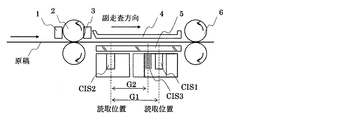
図1は画像読取装置の断面図であり、図2は画像読取装置の上面図であり、機構概要を示すものである。イメージセンサにCISを使用した例を説明する。 FIG. 1 is a cross-sectional view of the image reading apparatus, and FIG. 2 is a top view of the image reading apparatus, showing an outline of the mechanism. An example using CIS for an image sensor will be described.
図2に示すように3本のCIS1、CIS2、CIS3が千鳥状に配置されている。図1において原稿は右から挿入される。原稿挿入センサ1が原稿を検知すると、(図示していない)搬送モータにより搬送ローラ:前2、搬送ローラ:後6が回転し、CIS内の(図示していない)原稿照明用光源が点灯する。その後、レジストセンサ3により原稿先端を検知し、原稿の搬送経路における位置を逐次認識する。原稿画像(下面)はCIS2で読取られた後CIS1、CIS3に読み取られる。
As shown in FIG. 2, three CIS1, CIS2, and CIS3 are arranged in a staggered pattern. In FIG. 1, the document is inserted from the right. When the
CIS2の読取信号はCIS2とCIS1間の副走査に要する時間だけ遅延され、CIS3の読取信号はCIS3とCIS1間の副走査に要する時間だけ遅延され、CIS1、CIS2、CIS3の各信号は合成され、1ライン化された読取信号を得る。原稿画像は順次読取られ、搬送ローラ:後6を経て排出される。
The CIS2 read signal is delayed by the time required for sub-scanning between CIS2 and CIS1, the CIS3 read signal is delayed by the time required for sub-scanning between CIS3 and CIS1, and the CIS1, CIS2, and CIS3 signals are combined, A one-line read signal is obtained. The document image is sequentially read and discharged through the
図2においては(動作を上面から見ると)原稿は上から下へと搬送される。各CISの有効読取範囲は隣接するCISの有効読取範囲と重複して配置されている。各CISの有効読取範囲は各時点で使用する画像信号を得るための実行読取範囲を持ち、その各実行読取範囲は(主走査方向の)読取幅は一定で有効読取範囲内で(主走査方向、図2であれば左右方向)で、独立して任意に設定できる。この設定はCIS1の場合は読取開始位置P1a、CIS2はP2a、CIS3はP3aを設定することにより行う。 In FIG. 2, the document is conveyed from top to bottom (when the operation is viewed from the top). The effective reading range of each CIS overlaps with the effective reading range of the adjacent CIS. The effective reading range of each CIS has an effective reading range for obtaining an image signal to be used at each time point. Each effective reading range has a constant reading width (in the main scanning direction) and within the effective reading range (in the main scanning direction). In FIG. 2, left and right direction) can be arbitrarily set independently. This setting is performed by setting the reading start position P1a for CIS1, P2a for CIS2, and P3a for CIS3.
各実行読取範囲は原稿読取範囲、左位置検知範囲、右位置検知範囲を持つ。各原稿読取範囲は左重複読取範囲、右重複読取範囲を持つ。実行読取範囲を移動すると左右重複読取範囲を含む原稿読取範囲、左右位置検知範囲が同一量、同一方向に移動する。なお、本形態ではCIS1の左位置検知範囲、左重複読取範囲、CIS3の右位置検知範囲、右重複読取範囲は使用しない。また、原稿読取範囲は必ずしも重複させる必要はないが、本形態では重複した場合で説明する。 Each execution reading range has a document reading range, a left position detection range, and a right position detection range. Each document reading range has a left overlapping reading range and a right overlapping reading range. When the effective reading range is moved, the document reading range including the left and right overlapping reading range and the left and right position detection range move in the same amount and in the same direction. In this embodiment, the CIS1 left position detection range, left overlap reading range, CIS3 right position detection range, and right overlap reading range are not used. In addition, the document reading ranges do not necessarily have to be overlapped, but in the present embodiment, description will be made on the case where they overlap.
(2組の繋ぎ目毎の)重複した信号を使用した繋ぎ目を補正し(後述)、読取信号を得る。この読取においてCIS1、CIS2、CIS3の主走査方向、副走査方向の位置関係が正確に調整、保持されていることが必要である。以下その位置関係を調整、保持する方法を説明する。 The seam using the duplicated signal (for every two sets of seams) is corrected (described later) to obtain a read signal. In this reading, it is necessary that the positional relationship of the CIS1, CIS2, and CIS3 in the main scanning direction and the sub-scanning direction is accurately adjusted and held. A method for adjusting and maintaining the positional relationship will be described below.
図1、2におけるコンタクトガラス5(又は読取背面部材4、以降は代表してコンタクトガラス5と記載する。)には各CIS左右位置検知範囲に対応した位置に副走査方向に平行な細線L1a、L2a、L3aと45°傾斜した細線L1b、L2b、L3bが設けられている。 The contact glass 5 (or the reading back member 4, hereinafter referred to as the contact glass 5) in FIGS. 1 and 2 is a thin line L1a parallel to the sub-scanning direction at a position corresponding to each CIS left / right position detection range. Fine lines L1b, L2b, and L3b inclined by 45 ° and L2a and L3a are provided.
本形態の画像読取装置は各CISの読取範囲を調整モード、原稿読取モードで切り替える機能も持つ。なお位置調整にあたってはCIS1を基準とし、読取範囲は変更しない。かつ、副走査方向の遅延も行わない(CIS1に対応した遅延手段は無い。)CIS2の調整(読取範囲、遅延量)後、CIS3の調整を行う。 The image reading apparatus of this embodiment also has a function of switching the reading range of each CIS between the adjustment mode and the document reading mode. The position adjustment is based on CIS1, and the reading range is not changed. Also, no delay in the sub-scanning direction is performed (there is no delay means corresponding to CIS1). After adjusting CIS2 (reading range and delay amount), CIS3 is adjusted.
調整モードの読取範囲は各CISの実行読取範囲を使用する。また、原稿画像読取モードの読取範囲は各CIS1、CIS2、CIS3の重複読取範囲を含む原稿読取範囲を使用する。重複読取範囲の画像信号は補正され(方法は後述する。)、1ライン化された画像信号に組み込まれる。 The reading range in the adjustment mode uses the execution reading range of each CIS. Further, the reading range in the document image reading mode uses the document reading range including the overlapping reading ranges of CIS1, CIS2, and CIS3. The image signal in the overlapping reading range is corrected (a method will be described later) and incorporated into the image signal that has been made into one line.
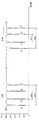
図3は調整モードでコンタクトガラスの細線を読取ったときの画像信号である。主走査の並びはCIS1の実行読取範囲の左端P1aに始まり、CIS1の実行読取範囲の右端P1bに至り、CIS2の実行読取範囲の左端P2aに飛び、CIS2の実行読取範囲の右端P2bに至り、同様にCIS3の実行読取範囲の左端P3aに飛び、CIS3の実行読取範囲の右端P3bに至り主走査1周期と成し、走査を繰り返す。 FIG. 3 shows an image signal when a thin line of the contact glass is read in the adjustment mode. The main scanning sequence starts at the left end P1a of the CIS1 execution reading range, reaches the right end P1b of the CIS1 execution reading range, jumps to the left end P2a of the CIS2 execution reading range, and reaches the right end P2b of the CIS2 execution reading range. At the same time, it jumps to the left end P3a of the CIS3 execution reading range, reaches the right end P3b of the CIS3 execution reading range, forms one main scanning period, and repeats scanning.
A群の波形はCIS1、CIS2間の繋ぎに対応した波形であり、B群はCIS2、CIS3に対応している。谷ピーク波形1b、1a、2b、2a、3b、3a、4a、4bはコンタクトガラス5上の細線L1b、L1a、L2b、L2a、L3b、L3a、L4a、L4bを読み取った信号に対応している。
The waveform of group A corresponds to the connection between CIS1 and CIS2, and group B corresponds to CIS2 and CIS3. The
A群の波形において、間隔SL1は細線L1a、細線L2aに対応し、CIS1、CIS2の主走査方向の位置関係を表している。CIS1、CIS2の主走査方向相対位置(つまり、重複区間の長さ)が変化すると間隔SL1は変化する。また間隔SG1も変化する。なお、CIS1、CIS2が副走査方向に移動しても、間隔SL1は変らない。しかし、細線L1b、L2bは傾斜を持つため間隔SG1は変化する。 In the waveform of the A group, the interval SL1 corresponds to the thin line L1a and the thin line L2a, and represents the positional relationship between the CIS1 and CIS2 in the main scanning direction. When the relative position in the main scanning direction of CIS1 and CIS2 (that is, the length of the overlapping section) changes, the interval SL1 changes. The interval SG1 also changes. Even if CIS1 and CIS2 move in the sub-scanning direction, the interval SL1 does not change. However, since the thin lines L1b and L2b are inclined, the interval SG1 changes.
同様にB群の波形においては、間隔SL2は細線L3a、細線L4aに対応し、CIS2、CIS3の主走査方向の位置関係を表している。CIS2、CIS3の主走査方向相対位置(つまり、重複区間の長さ)が変化すると間隔SL2は変化する。また間隔SG2も変化する。なおCIS1,CIS2が副走査方向に移動しても、間隔SL1は変らない。しかし、細線L1b、L2bは傾斜を持つため間隔SG2は変化する。 Similarly, in the waveform of group B, the interval SL2 corresponds to the thin line L3a and the thin line L4a, and represents the positional relationship between the CIS2 and CIS3 in the main scanning direction. When the relative position in the main scanning direction of CIS2 and CIS3 (that is, the length of the overlapping section) changes, the interval SL2 changes. The interval SG2 also changes. Even if CIS1 and CIS2 move in the sub-scanning direction, the interval SL1 does not change. However, since the thin lines L1b and L2b are inclined, the interval SG2 changes.
調整方法を説明する。前記した各区間SL1、SG1、SL2、SG2が予め設定された各定数K1、K2、K3(調整目標値)に一致させることがCIS1、CIS2、CIS3の繋ぎ目の調整である。
SL1=SL2=K1
SG1=K2
SG2=K3
The adjustment method will be described. The adjustment of the joints of CIS1, CIS2, and CIS3 is to make each of the sections SL1, SG1, SL2, and SG2 coincide with preset constants K1, K2, and K3 (adjustment target values).
SL1 = SL2 = K1
SG1 = K2
SG2 = K3
なお、構成によってはSL1、SG1、SL2、SG2の調整目標値を個別に設定する必要がある。ここで谷ピーク波形1b、1a、2b、2a、3b、3a、4a、4bの各位置の相対関係を変えず時間軸上で左右に移動しても、問題が無い。経時や環境変動等でCIS1、CIS2、CIS3が相対位置を変えず位置変動する寸法は僅かであり、問題とならない。なお、相対位置が変化した場合は僅かでも読取画像上で問題となる。
Depending on the configuration, adjustment target values of SL1, SG1, SL2, and SG2 need to be set individually. Here, there is no problem even if the
調整の前提となる調整目標値の対応する値として、主走査方向においてCIS1とCIS2の重複区間は2.709mm(64画素分)とし、副走査方向の間隔は25.400mm(600画素分)とする。CIS1とCIS2の重複区間は2.709mm(64画素分)とし、副走査方向の間隔は調整初期値を23.368mm(552画素分すなわち552ライン分)とする。なお、副走査方向の間隔目標値は主走査方向直線が描かれているテストチャートの読取(又はコピー)画像における繋ぎ目の段差が、CIS2又はCIS3の遅延量を調整して最小とさせる値を目標値としても良い。なお図3の時間軸は画素間隔、したがって各機構上の寸法に対応している。 As values corresponding to the adjustment target values that are the preconditions for adjustment, the overlapping section of CIS1 and CIS2 in the main scanning direction is 2.709 mm (64 pixels), and the interval in the sub-scanning direction is 25.400 mm (600 pixels). The overlap section between CIS1 and CIS2 is 2.709 mm (64 pixels), and the adjustment in the sub-scanning direction is 23.368 mm (552 pixels, that is, 552 lines). The interval target value in the sub-scanning direction is a value that minimizes the level difference of the joint in the read (or copy) image of the test chart on which the straight line in the main scanning direction is drawn by adjusting the delay amount of CIS2 or CIS3. It may be a target value. Note that the time axis in FIG. 3 corresponds to the pixel interval, and thus the dimensions on each mechanism.
調整ではまず、CIS1とCIS2の関係におけるSL1を目標値K1にするためCIS2の読取開始位置P2a(実行読取範囲の左端)を調整する。実行読取長は一定のため、読取開始位置P2aを決めると実行読取範囲の読取終了位置P2bは自ずと決まる。読取開始位置P2aを調整することにより、SL1をK1に一致させる。その後CIS1とCIS2の副走査方向の間隔を、CIS2の画像信号遅延量を調整し、間隔SG1を目標値K2に調整する。CIS1の実行読取範囲は固定している。またCIS1の信号は遅延をしない。 In the adjustment, first, the reading start position P2a of CIS2 (the left end of the execution reading range) is adjusted in order to set SL1 in the relationship between CIS1 and CIS2 to the target value K1. Since the effective reading length is constant, when the reading start position P2a is determined, the reading end position P2b of the effective reading range is naturally determined. SL1 is matched with K1 by adjusting the reading start position P2a. Thereafter, the interval between the CIS1 and CIS2 in the sub-scanning direction is adjusted by adjusting the image signal delay amount of the CIS2, and the interval SG1 is adjusted to the target value K2. The execution reading range of CIS1 is fixed. The CIS1 signal is not delayed.
その後、CIS2とCIS3の関係におけるSL2を目標値K2にするためCIS3の読取開始位置P3a(実行読取範囲の左端)を調整する。実行読取長は一定のため、読取開始位置P3aを決めると実行読取範囲の読取終了位置P3bは自ずと決まる。読取開始位置P3aを調整することにより、SL2をK1に一致させる。その後CIS2とCIS3の副走査方向の間隔を、CIS3の画像信号遅延量を調整し間隔SG2を目標値K3に調整する。 Thereafter, the reading start position P3a of CIS3 (the left end of the execution reading range) is adjusted in order to set SL2 in the relationship between CIS2 and CIS3 to the target value K2. Since the effective reading length is constant, when the reading start position P3a is determined, the reading end position P3b of the effective reading range is naturally determined. SL2 is made to coincide with K1 by adjusting the reading start position P3a. Thereafter, the interval between the CIS2 and CIS3 in the sub-scanning direction is adjusted by adjusting the image signal delay amount of the CIS3, and the interval SG2 is adjusted to the target value K3.
原稿画像読取モードにおいては、各CISの原稿読取範囲をのみを1ライン化した画像信号を使用する。重複読取範囲の処理(繋ぎ目の信号処理)は後述する。 In the document image reading mode, an image signal in which only one document reading range of each CIS is made into one line is used. The overlap reading range processing (joint signal processing) will be described later.
図4はCIS1とCIS2の繋ぎ目の信号処理の様子を図示したものである。CIS1の右側のCIS1右重複読取区間とCIS2の左側のCIS2左重複読取区間が64画素重複読取する様に構成されている。CIS1右重複読取区間の左側は重複読取以外のCIS1原稿画像読取範囲があり、CIS2左重複読取区間の右側は重複読取以外のCIS2原稿画像読取範囲がある。CIS1右重複読取区間の更に右側にはCIS1右位置検知区間があり、CIS2左重複読取区間のさらに左側にはCIS2左位置検知区間がある。 FIG. 4 illustrates the signal processing at the joint between CIS1 and CIS2. The CIS1 right overlapping reading section on the right side of CIS1 and the CIS2 left overlapping reading section on the left side of CIS2 are configured to perform 64 pixel overlapping reading. The left side of the CIS1 right overlapping reading section has a CIS1 original image reading range other than the overlapping reading, and the right side of the CIS2 left overlapping reading section has a CIS2 original image reading range other than the overlapping reading. There is a CIS1 right position detection section on the right side of the CIS1 right overlap reading section, and a CIS2 left position detection section on the further left side of the CIS2 left overlap reading section.
CIS1右重複読取区間の画像信号D1-2(n)とCIS2左重複読取区間の画像信号D2-2(n)を使用し、CIS1、CIS2繋ぎ補正区間の画像信号D12(n)を次の式を使用して生成する。
D12(n)=(k−n)/k×D1-2(k−n)+n/k×D2-2(n)
Using the image signal D1-2 (n) in the CIS1 right overlap reading section and the image signal D2-2 (n) in the CIS2 left overlap reading section, the image signal D12 (n) in the CIS1 and CIS2 joint correction section is Generate using.
D12 (n) = (k−n) / k × D1-2 (k−n) + n / k × D2-2 (n)
この画像信号D12(n)と重複読取以外のCIS1原稿画像読取範囲の画像信号D1-1と重複読取以外のCIS2原稿画像読取範囲の画像信号D2-3により、CIS1とCIS2の繋ぎ目近傍の1ライン化された読取信号を図4の下段に示す。CIS1の右側の画像信号からCIS2の左側画像信号のレベルに滑らかに変化させることにより、CIS1とCIS2の特性差や微小な位置ズレがあっても、画像上で目立たなくすることを狙っている。 The image signal D12 (n), the image signal D1-1 of the CIS1 original image reading range other than the duplicate reading, and the image signal D2-3 of the CIS2 original image reading range other than the duplicate reading are 1 near the joint of CIS1 and CIS2. The lined read signal is shown in the lower part of FIG. By smoothly changing the image signal on the right side of CIS1 to the level of the image signal on the left side of CIS2, it aims to make the image inconspicuous even if there is a characteristic difference between CIS1 and CIS2.
CIS2とCIS3の繋ぎ目の信号処理も、前記したCIS1とCIS2の繋ぎ目の信号処理と同様に実施する。 The signal processing at the joint between CIS2 and CIS3 is performed in the same manner as the signal processing at the joint between CIS1 and CIS2.
本形態を実施することにより、以下の効果を奏する。つまり、千鳥状にイメージセンサを配置した画像読取装置においては、イメージセンサの一部分を使用して、イメージセンサの位置や各イメージセンサの間隔(位置関係)を検知しているので、検知に特別な検知手段を必要とせずに、正確な検知ができる。 By implementing this embodiment, the following effects can be obtained. In other words, in an image reading apparatus in which image sensors are arranged in a staggered pattern, a part of the image sensor is used to detect the position of the image sensor and the interval (positional relationship) between the image sensors. Accurate detection is possible without the need for detection means.
また、イメージセンサ位置の基準となる(位置関係が正確に管理された)細線がコンタクトガラス5又は読取背面部材4に描かれているので、正確な位置関係が検知できる。
Further, since the thin line that serves as a reference for the position of the image sensor (the positional relationship is accurately managed) is drawn on the
また、イメージセンサ位置の基準となる(位置関係が正確に管理された)細線が2本を1組とした複数組から構成されているので、各イメージセンサ読取の繋ぎ部の主、副走査方向の位置関係を、同時に同一部材で簡易に検出できる。 In addition, since the thin lines serving as the reference for the position of the image sensor (the positional relationship is accurately managed) are composed of a plurality of sets of two sets as one set, the main and sub-scanning directions of the connecting portions of each image sensor reading Can be easily detected simultaneously with the same member.
隣接したイメージセンサの原稿読取範囲が重複した、千鳥状にイメージセンサを配置した画像読取装置においては、(主走査方向のイメージセンサの位置に関わる)その重複した原稿読取範囲の寸法を上記の検知方法を使用した信号をもとに調整しているので、正確な重複した原稿読取範囲の寸法の主走査方向の繋ぎ調整ができる。 In an image reading apparatus in which the image reading ranges of adjacent image sensors overlap and the image sensors are arranged in a staggered manner, the size of the overlapping document reading range (related to the position of the image sensor in the main scanning direction) is detected as described above. Since the adjustment is performed based on the signal using the method, it is possible to accurately adjust the dimension of the overlapping document reading range in the main scanning direction.
千鳥状にイメージセンサを配置した画像読取装置においては、副走査方向のイメージセンサの位置関係を相殺するため、相対的に先に読み込んだ画像信号の遅延をするに当たり、上記の検知方法を使用した信号をもとに、遅延量を調整しているので、副走査方向の正確な繋ぎ調整ができる。 In the image reading apparatus in which the image sensors are arranged in a staggered pattern, the above detection method is used to delay the image signal read earlier in order to cancel the positional relationship of the image sensors in the sub-scanning direction. Since the amount of delay is adjusted based on the signal, it is possible to accurately adjust the connection in the sub-scanning direction.
千鳥状にイメージセンサを配置した画像読取装置においては、主走査方向及び副走査方向の位置関係の調整をするにあたり、先に主走査方向の調整を行い、次に副走査方向の調整を行うことで、全体の位置関係の調整を迅速に行うことができる。 In an image reading apparatus in which image sensors are arranged in a staggered pattern, the main scanning direction is adjusted first, and then the sub scanning direction is adjusted before adjusting the positional relationship between the main scanning direction and the sub scanning direction. Thus, the overall positional relationship can be adjusted quickly.
なお、上述した形態は本発明の画像読取装置を実施するための最良のものであるが、かかる実施形式に限定するものではなく、本発明の要旨を変更しない範囲内においてその実施形式を種々変形することが可能である。 The above-described embodiment is the best for carrying out the image reading apparatus of the present invention. However, the present invention is not limited to this embodiment, and various modifications can be made to the embodiment without departing from the scope of the present invention. Is possible.
本発明の画像読取装置を搭載したFAX、スキャナ、MFP(Multi Functional Peripheral)等の開発が望まれる。 Development of a FAX, scanner, MFP (Multi Functional Peripheral), etc., equipped with the image reading apparatus of the present invention is desired.
1 原稿挿入センサ
2 搬送ローラ:前
3 レジストセンサ
4 読取背面部材
5 コンタクトガラス
6 搬送ローラ:後
DESCRIPTION OF
Claims (7)
各イメージセンサの読取範囲内に、原稿読取範囲及び当該イメージセンサの位置を検知するための位置検知範囲を有し、
前記位置検知範囲内で読み取った画像信号により、各イメージセンサの位置関係を検知することを特徴とする画像読取装置。 In the image reading apparatus in which a plurality of image sensors are arranged in a staggered manner and the reading ranges of the image sensors adjacent to each other are overlapped in the main scanning direction,
Within the reading range of each image sensor, a document reading range and a position detection range for detecting the position of the image sensor,
An image reading apparatus for detecting a positional relationship between image sensors based on an image signal read within the position detection range.
各イメージセンサの読取範囲内に、原稿読取範囲及び当該イメージセンサの位置を検知するための位置検知範囲を有し、当該位置検知範囲内で読み取った画像信号により、各イメージセンサの位置関係を検知する際に、
前記位置検知範囲で読み取った画像信号により、一のイメージセンサの原稿読取範囲と他のイメージセンサの原稿読取範囲との相対位置関係を所定値に設定し、主走査方向における位置調整を行う工程と、
前記位置検知範囲で読み取った画像信号により、遅延量を調整し、副走査方向における位置調整を行う工程を有することを特徴とする位置調整方法。 In the position adjustment method of the image reading apparatus in which a plurality of image sensors are staggered and the reading ranges of the image sensors adjacent to each other are overlapped in the main scanning direction,
Each image sensor has a reading range and a position detection range for detecting the position of the image sensor, and the positional relationship between the image sensors is detected by an image signal read within the position detection range. When doing
A step of adjusting the position in the main scanning direction by setting a relative positional relationship between a document reading range of one image sensor and a document reading range of another image sensor to a predetermined value based on an image signal read in the position detection range; ,
A position adjustment method comprising adjusting a delay amount based on an image signal read in the position detection range and performing position adjustment in the sub-scanning direction.
Priority Applications (1)
| Application Number | Priority Date | Filing Date | Title |
|---|---|---|---|
| JP2006064104A JP2007243664A (en) | 2006-03-09 | 2006-03-09 | Image reader and position adjustment method |
Applications Claiming Priority (1)
| Application Number | Priority Date | Filing Date | Title |
|---|---|---|---|
| JP2006064104A JP2007243664A (en) | 2006-03-09 | 2006-03-09 | Image reader and position adjustment method |
Publications (1)
| Publication Number | Publication Date |
|---|---|
| JP2007243664A true JP2007243664A (en) | 2007-09-20 |
Family
ID=38588738
Family Applications (1)
| Application Number | Title | Priority Date | Filing Date |
|---|---|---|---|
| JP2006064104A Pending JP2007243664A (en) | 2006-03-09 | 2006-03-09 | Image reader and position adjustment method |
Country Status (1)
| Country | Link |
|---|---|
| JP (1) | JP2007243664A (en) |
Cited By (2)
| Publication number | Priority date | Publication date | Assignee | Title |
|---|---|---|---|---|
| JP2010171569A (en) * | 2009-01-21 | 2010-08-05 | Panasonic Corp | Image reading apparatus and image synthesizing method thereof |
| US10757287B2 (en) | 2018-09-28 | 2020-08-25 | Ricoh Company, Ltd. | Image reading device, image forming apparatus, and image reading method |
Citations (11)
| Publication number | Priority date | Publication date | Assignee | Title |
|---|---|---|---|---|
| JPS6024765A (en) * | 1983-07-20 | 1985-02-07 | Sanyo Electric Co Ltd | Adjusting method for image scanner |
| JPS62101170A (en) * | 1985-10-28 | 1987-05-11 | Toshiba Corp | Picture reader |
| JPS6348053A (en) * | 1986-08-15 | 1988-02-29 | Canon Inc | Picture information inputting device |
| JPS63234765A (en) * | 1987-03-24 | 1988-09-30 | Dainippon Screen Mfg Co Ltd | Method and device for connecting-processing line image sensor |
| JPH01144853A (en) * | 1987-12-01 | 1989-06-07 | Mitsubishi Electric Corp | Image read system |
| JP2000175001A (en) * | 1998-12-04 | 2000-06-23 | Matsushita Electric Ind Co Ltd | Image data correction method in image reader |
| JP2002057860A (en) * | 2000-08-10 | 2002-02-22 | Pfu Ltd | Image reader |
| JP2002314768A (en) * | 2001-04-10 | 2002-10-25 | Graphtec Corp | Image reader |
| JP2003046736A (en) * | 2001-05-22 | 2003-02-14 | Graphtec Corp | Image scanner |
| JP2006025289A (en) * | 2004-07-09 | 2006-01-26 | Matsushita Electric Ind Co Ltd | Marker apparatus and image reading apparatus provided with the same |
| JP2006135901A (en) * | 2004-11-09 | 2006-05-25 | Seiko Instruments Inc | Image processor |
-
2006
- 2006-03-09 JP JP2006064104A patent/JP2007243664A/en active Pending
Patent Citations (11)
| Publication number | Priority date | Publication date | Assignee | Title |
|---|---|---|---|---|
| JPS6024765A (en) * | 1983-07-20 | 1985-02-07 | Sanyo Electric Co Ltd | Adjusting method for image scanner |
| JPS62101170A (en) * | 1985-10-28 | 1987-05-11 | Toshiba Corp | Picture reader |
| JPS6348053A (en) * | 1986-08-15 | 1988-02-29 | Canon Inc | Picture information inputting device |
| JPS63234765A (en) * | 1987-03-24 | 1988-09-30 | Dainippon Screen Mfg Co Ltd | Method and device for connecting-processing line image sensor |
| JPH01144853A (en) * | 1987-12-01 | 1989-06-07 | Mitsubishi Electric Corp | Image read system |
| JP2000175001A (en) * | 1998-12-04 | 2000-06-23 | Matsushita Electric Ind Co Ltd | Image data correction method in image reader |
| JP2002057860A (en) * | 2000-08-10 | 2002-02-22 | Pfu Ltd | Image reader |
| JP2002314768A (en) * | 2001-04-10 | 2002-10-25 | Graphtec Corp | Image reader |
| JP2003046736A (en) * | 2001-05-22 | 2003-02-14 | Graphtec Corp | Image scanner |
| JP2006025289A (en) * | 2004-07-09 | 2006-01-26 | Matsushita Electric Ind Co Ltd | Marker apparatus and image reading apparatus provided with the same |
| JP2006135901A (en) * | 2004-11-09 | 2006-05-25 | Seiko Instruments Inc | Image processor |
Cited By (2)
| Publication number | Priority date | Publication date | Assignee | Title |
|---|---|---|---|---|
| JP2010171569A (en) * | 2009-01-21 | 2010-08-05 | Panasonic Corp | Image reading apparatus and image synthesizing method thereof |
| US10757287B2 (en) | 2018-09-28 | 2020-08-25 | Ricoh Company, Ltd. | Image reading device, image forming apparatus, and image reading method |
Similar Documents
| Publication | Publication Date | Title |
|---|---|---|
| US7688488B2 (en) | Image reading device and image forming apparatus including the same | |
| JP4861354B2 (en) | Image reading apparatus and image forming apparatus | |
| JP2015201843A (en) | Image reader and correction method of the same | |
| JP2005114769A (en) | Image forming apparatus | |
| US9191540B2 (en) | Image processing device and method of acquiring amount of density deviation of light-emitting-element group | |
| JP7358180B2 (en) | Image reading device, its control method, and program | |
| JP7183669B2 (en) | Image reading device, image forming device and image reading method | |
| JP5338291B2 (en) | Image forming apparatus | |
| US9383675B2 (en) | Image processing device and method of acquiring amount of positional deviation of light-emitting-element array | |
| EP2444850A2 (en) | Image forming apparatus and program | |
| JP4571027B2 (en) | Image reading apparatus adjustment method, image reading apparatus and image forming apparatus using the same | |
| JP2007243664A (en) | Image reader and position adjustment method | |
| JP4808075B2 (en) | Image reading apparatus, program, and recording medium | |
| JP2009171171A (en) | Image reading apparatus and image forming apparatus | |
| JP6524001B2 (en) | Image reading apparatus, control method and control program | |
| US9703248B2 (en) | Curling detection device, image forming apparatus, curling detection method, image adjustment method, recording medium storing a curling detection program, and recording medium storing an image adjustment program | |
| JP5884460B2 (en) | Image reading apparatus, image forming apparatus, image reading method, and image reading program | |
| JP6905393B2 (en) | Image reader | |
| JP2009010507A (en) | Image reader and image forming apparatus | |
| JP4638791B2 (en) | Sheet position detecting device and image forming apparatus | |
| JP4074527B2 (en) | Angle detection device and projector equipped with the same | |
| US11750753B2 (en) | Image reading device, image forming apparatus, and image reading method | |
| JP4862782B2 (en) | Image reading device | |
| CN108347546A (en) | The manufacturing method of scanner and scanner | |
| JP2014060557A (en) | Image forming apparatus and image forming method |
Legal Events
| Date | Code | Title | Description |
|---|---|---|---|
| A621 | Written request for application examination |
Free format text: JAPANESE INTERMEDIATE CODE: A621 Effective date: 20090213 |
|
| A977 | Report on retrieval |
Free format text: JAPANESE INTERMEDIATE CODE: A971007 Effective date: 20100709 |
|
| A131 | Notification of reasons for refusal |
Free format text: JAPANESE INTERMEDIATE CODE: A131 Effective date: 20100727 |
|
| A521 | Written amendment |
Free format text: JAPANESE INTERMEDIATE CODE: A523 Effective date: 20100927 |
|
| A131 | Notification of reasons for refusal |
Free format text: JAPANESE INTERMEDIATE CODE: A131 Effective date: 20101207 |
|
| A02 | Decision of refusal |
Free format text: JAPANESE INTERMEDIATE CODE: A02 Effective date: 20110405 |