JP6905393B2 - Image reader - Google Patents
Image reader Download PDFInfo
- Publication number
- JP6905393B2 JP6905393B2 JP2017117483A JP2017117483A JP6905393B2 JP 6905393 B2 JP6905393 B2 JP 6905393B2 JP 2017117483 A JP2017117483 A JP 2017117483A JP 2017117483 A JP2017117483 A JP 2017117483A JP 6905393 B2 JP6905393 B2 JP 6905393B2
- Authority
- JP
- Japan
- Prior art keywords
- amount
- document
- tilt
- inclination
- image
- Prior art date
- Legal status (The legal status is an assumption and is not a legal conclusion. Google has not performed a legal analysis and makes no representation as to the accuracy of the status listed.)
- Active
Links
Images


Landscapes
- Facsimile Scanning Arrangements (AREA)
- Editing Of Facsimile Originals (AREA)
Description
本発明は、原稿の画像を読み取る画像読取装置に関する。 The present invention relates to an image reader that reads an image of a document.
従来、複写機等に使用される画像読取装置は、いわゆる流し読みモードで動作するものがある。流し読みモードにおいて、原稿トレイ上の原稿は、原稿給送装置により一枚ずつ原稿台ガラス上へ給送される。原稿の搬送路に固定された読取ユニットは、搬送される原稿の画像を読み取る。流し読みモードにおいて原稿が傾いた状態で搬送されると原稿の画像が傾いて読み取られる。原稿が傾いた状態で画像が読み取られる問題を解決するために、特許文献1は、読み取った画像データから原稿の傾きを検出して画像データを補正する。
Conventionally, some image reading devices used in copiers and the like operate in a so-called scanning mode. In the scanning mode, the documents on the document tray are fed one by one onto the platen glass by the document feeding device. The scanning unit fixed to the document transport path reads the image of the document to be transported. When the document is conveyed in a tilted state in the scanning mode, the image of the document is tilted and read. In order to solve the problem that the image is read in a state where the original is tilted,
特許文献2は、原稿の一面の画像を読み取る第一読取ユニットおよび原稿の他面の画像を読み取る第二読取ユニットを備え、原稿の一度の搬送で原稿の両面の画像を読み取る画像読取装置を開示している。画像の傾きは、第一読取ユニットにより読み取られた画像データから検出される第一傾き量、第二読取ユニットにより読み取られた画像データから検出される原稿の第二傾き量、又は第一傾き量と第二傾き量の平均値に基づいて補正される。特許文献2によれば、画像の傾きの検出精度が向上する。
しかし、特許文献2においては、第一読取ユニットの読取位置と第二読取ユニットの読取位置が離れているので、第一傾き量が検出されてから第二傾き量が検出されるまで時間がかかる。第二傾き量が検出されるまで画像の傾きを決定できないので、原稿の画像の読み取り開始から読み取り画像データが得るまでに時間がかかるという問題がある。
However, in
そこで、本発明は、画像読取装置の生産性の低下を抑制しつつ、画像データの傾き補正の精度の低下を抑制することを目的とする。
Therefore, an object of the present invention is to suppress a decrease in the accuracy of tilt correction of image data while suppressing a decrease in the productivity of the image reading device.
前記課題を解決するため、本発明の一実施例による画像読取装置は、
原稿を搬送する原稿搬送手段と、
前記原稿搬送手段により搬送される前記原稿の第一の面の画像を読み取る第一の画像読取手段と、
前記原稿が搬送される搬送方向において前記第一の画像読取手段の下流に配置され、前記原稿搬送手段により搬送される前記原稿の前記第一の面とは反対の第二の面の画像を読み取る第二の画像読取手段と、
前記搬送方向において前記第一の画像読取手段の上流に配置され、前記原稿搬送手段により搬送される前記原稿を検出する第一の原稿検出手段と、
前記搬送方向において前記第一の画像読取手段の上流且つ前記搬送方向に垂直な幅方向において前記第一の原稿検出手段とは異なる位置に配置され、前記原稿搬送手段により搬送される前記原稿を検出する第二の原稿検出手段と、
前記第一の原稿検出手段が前記原稿を検出したタイミングと前記第二の原稿検出手段が前記原稿を検出したタイミングとに基づいて前記原稿の第一傾き量を検出する第一の傾き量検出手段と、
前記第一の画像読取手段により読み取られた前記第一の面の画像を表す画像データに基づいて前記原稿の第二傾き量を検出する第二の傾き量検出手段と、
前記第二の画像読取手段により読み取られた前記第二の面の画像を表す画像データに基づいて前記原稿の第三傾き量を検出する第三の傾き量検出手段と、
前記第一傾き量と前記第二傾き量との差の絶対値が第一の所定値以下である場合は前記第一の面の前記画像データの傾きを補正するための第一の傾き補正量及び前記第二の面の前記画像データの傾きを補正するための第二の傾き補正量を前記第二傾き量に基づいて決定し、前記第一傾き量と前記第二傾き量との差の絶対値が前記第一の所定値より大きい場合は前記第一の傾き補正量及び前記第二の傾き補正量を前記第一傾き量と前記第三傾き量とに基づいて決定する傾き補正量決定手段と、
前記傾き補正量決定手段によって決定された補正量に基づいて、前記第一の面の前記画像データの傾き及び前記第二の面の前記画像データの傾きを補正する補正手段と、
を備えることを特徴とする。
In order to solve the above problems, the image reading device according to the embodiment of the present invention is used.
Document transport means for transporting documents and
A first image reading means for reading an image of the first surface of the document conveyed by the document conveying means, and
The document is arranged downstream of the first image reading means in the conveying direction is conveyed to read an image of the opposite second surface from said first surface of said original conveyed by said original conveying means The second image reading means,
A first document detecting means, which is arranged upstream of the first image reading means in the transport direction and detects the document transported by the document transporting means, and a first document detecting means.
The document is located upstream of the first image reading means in the transport direction and at a position different from that of the first document detecting means in the width direction perpendicular to the transport direction, and detects the document transported by the document transporting means. Second document detection means to be
The first tilt amount detecting means for detecting the first tilt amount of the document based on the timing when the first document detecting means detects the document and the timing when the second document detecting means detects the document. When,
A second tilt amount detecting means for detecting the second tilt amount of the document based on image data representing the image of the first surface read by the first image reading means, and a second tilt amount detecting means.
A third tilt amount detecting means for detecting the third tilt amount of the document based on image data representing the image of the second surface read by the second image reading means, and a third tilt amount detecting means.
Absolute value first inclination correction for correcting a tilt of the image data of the first is less than or equal to the predetermined value before Symbol first aspect of the difference between the second tilt amount and the first amount of inclination The amount and the second tilt correction amount for correcting the tilt of the image data on the second surface are determined based on the second tilt amount, and the difference between the first tilt amount and the second tilt amount. absolute value tilt correction if greater than said first predetermined value is determined based pre Symbol first inclination correction amount and the second inclination correction amount and the third amount of inclination between the first inclination amount of Quantitative means and
A correction means for correcting the inclination of the image data on the first surface and the inclination of the image data on the second surface based on the correction amount determined by the inclination correction amount determining means.
It is characterized by having.
本発明によれば、画像読取装置の生産性の低下を抑制しつつ、画像データの傾き補正の精度の低下を抑制することができる。
According to the present invention, it is possible to suppress a decrease in the productivity of the image reading device and a decrease in the accuracy of tilt correction of the image data.
以下、図面を参照して、本発明を実施するための形態を説明する。本実施例の画像読取装置100は、単独の装置であっても、他の機能と組み合わされた複写機やファクシミリ、あるいは他の複合機の一部であってもよい。
Hereinafter, embodiments for carrying out the present invention will be described with reference to the drawings. The
(画像読取装置)
図1は、画像読取装置100の断面図である。画像読取装置100は、原稿の画像を読み取るリーダーユニット(画像読取部)101およびリーダーユニット101へ原稿を給送する自動原稿給送装置(以下、ADFという)102を有する。複数枚の原稿を積み重ねた原稿束103は、原稿トレイ104に載置される。幅規制板105は、原稿束103の幅方向の端部に当接する。幅方向は、原稿の搬送方向(給送方向)CDに垂直であり、かつ原稿の表面に平行な方向である。原稿束103は、幅規制板105によって幅方向の移動が規制されて、原稿の傾きが抑制される。ピックアップローラ106は、原稿束103の最上位原稿を分離部114へ給送する。分離部114は、分離パッド107と分離ローラ108を有する。分離パッド107と分離ローラ108は、原稿束103から給送された原稿を1枚ずつ分離する。分離された1枚の原稿は、分離ローラ108から排出ローラ117までの原稿搬送路(以下、搬送路という)115上を搬送される。原稿は、原稿検出手段としての原稿検出器109を通り第一搬送ローラ110へ搬送される。第一搬送ローラ110は、原稿の斜行を補正するレジストレーションローラである。斜行が補正された原稿は、第二搬送ローラ111、第三搬送ローラ112および第四搬送ローラ113の順に搬送される。
(Image reader)
FIG. 1 is a cross-sectional view of the
第三搬送ローラ112と第四搬送ローラ113の間には、第一標準白色板(第一の基準反射部材)119が設けられている。原稿の表面(第一の面)の画像を読み取る第一の画像読取手段としての第一読取ユニット121は、表面読取位置(以下、第一読取位置)RP1で第一標準白色板119に対向して配置されている。第三搬送ローラ112と第四搬送ローラ113の間を通過する原稿は、第一読取位置RP1上を通る。第一読取ユニット121は、第一読取位置RP1上を通過する原稿の表面の画像を読み取る。第四搬送ローラ113を通過した原稿は、第五搬送ローラ132、第六搬送ローラ133および第七搬送ローラ116の順に搬送される。
A first standard white plate (first reference reflective member) 119 is provided between the
第五搬送ローラ132と第六搬送ローラ133の間には、第二標準白色板(第二の基準反射部材)129が設けられている。原稿の表面と反対の裏面(第二の面)の画像を読み取る第二の画像読取手段としての第二読取ユニット131は、裏面読取位置(以下、第二読取位置)RP2で第二標準白色板129に対向して配置されている。第五搬送ローラ132と第六搬送ローラ133の間を通過する原稿は、第二読取位置RP2上を通る。第二読取ユニット131は、第二読取位置RP2上を通過する原稿の裏面の画像を読み取る。第六搬送ローラ133を通過した原稿は、第七搬送ローラ116および排出ローラ117の順に搬送される。原稿は、排出ローラ117により排出トレイ118上に排出される。
A second standard white plate (second reference reflection member) 129 is provided between the
本実施例において、第一読取位置RP1は、原稿の搬送方向において第二読取位置RP2の上流に位置する。すなわち、第二読取ユニット131は、原稿の搬送方向において第一読取ユニット121の下流に配置されている。搬送路115上の原稿の表面の画像が第一読取ユニット121により読み取られた後、搬送方向の下流で搬送路115上の原稿の裏面の画像が第二読取ユニット131により読み取られる。
In this embodiment, the first reading position RP1 is located upstream of the second reading position RP2 in the document transport direction. That is, the
(画像読取動作)
次に、画像読取動作を説明する。画像読取装置100は、原稿搬送手段としてのADF102により搬送される原稿の画像を読み取る流し読みモードで動作可能である。画像読取装置100は、ADF102により第一読取ガラス120上を搬送される原稿の両面の画像を、原稿の一度の搬送で、第一読取ユニット121および第二読取ユニット131により読み取る。
(Image reading operation)
Next, the image reading operation will be described. The
まず、第一読取ユニット121により原稿の表面の画像を読み取る動作を説明する。第一読取ユニット121は、第一読取位置RP1で第一読取ガラス120を介して第一標準白色板119に対向して配置されている。第一読取ユニット121は、光源122および123、反射鏡124、125および126、結像レンズ127および第一ラインイメージセンサ128を有する。光源122および123は、第一読取位置RP1で第一標準白色板119と第一読取ガラス120の間を搬送される原稿へ光を照射する。原稿からの反射光は、反射鏡124、125および126により結像レンズ127へ導かれる。結像レンズ127は、反射光を第一ラインイメージセンサ128上に結像させる。第一ラインイメージセンサ128は、CCDなどの撮像素子(受光素子)がライン状に配置されている。第一ラインイメージセンサ128は、受光した反射光(光信号)を電気信号へ変換する光電変換手段である。第一ラインイメージセンサ128から出力される電気信号(アナログ信号)は、信号処理基板200(図2)へ入力される。信号処理基板200は、電気信号をアナログ信号からデジタル信号へ変換し、その後、デジタル信号に画像処理を行う。
First, an operation of reading an image on the surface of a document by the
次に、第二読取ユニット131により原稿の裏面の画像を読み取る動作を説明する。第二読取ユニット131は、第二読取位置RP2で第二読取ガラス130を介して第二標準白色板129に対向して配置されている。第二読取ユニット131は、光源134および135、反射鏡136、137および138、結像レンズ139および第二ラインイメージセンサ140を有する。光源134および135は、第二読取位置RP2で第二標準白色板129と第二読取ガラス130の間を搬送される原稿へ光を照射する。原稿からの反射光は、反射鏡136、137および138により結像レンズ139へ導かれる。結像レンズ139は、反射光を第二ラインイメージセンサ140上に結像させる。第二ラインイメージセンサ140は、CCDなどの撮像素子(受光素子)がライン状に配置されている。第二ラインイメージセンサ140は、受光した反射光(光信号)を電気信号へ変換する光電変換手段である。第二ラインイメージセンサ140から出力される電気信号(アナログ信号)は、信号処理基板200(図2)へ入力される。信号処理基板200は、電気信号をアナログ信号からデジタル信号へ変換し、その後、デジタル信号に画像処理を行う。
Next, an operation of scanning the image on the back surface of the document by the
(信号処理基板)
図2は、信号処理基板200のブロック図である。信号処理基板200は、原稿検出器109、第一ラインイメージセンサ128、第二ラインイメージセンサ140、搬送制御部205および操作パネル(操作部)206に電気的に接続されている。信号処理基板200は、第一AD変換器201、第二AD変換器202、CPU(制御部)203およびRAM(記憶部)204を有する。CPU203は、主走査カウンタ(第一のカウンタ)211および副走査カウンタ(第二のカウンタ)212を有する。
(Signal processing board)
FIG. 2 is a block diagram of the
第一ラインイメージセンサ128は、アナログ信号を第一AD変換器201へ送信する。第一AD変換器201は、第一ラインイメージセンサ128から入力されたアナログ信号を原稿の表面の画像のデジタル信号へ変換する。第一AD変換器201は、原稿の表面の画像のデジタル信号をCPU203へ送信する。
The first
第二ラインイメージセンサ140は、アナログ信号を第二AD変換器202へ送信する。第二AD変換器202は、第二ラインイメージセンサ140から入力されたアナログ信号を原稿の裏面の画像のデジタル信号へ変換する。第二AD変換器202は、原稿の裏面の画像のデジタル信号をCPU203へ送信する。
The second
CPU203は、第一ラインイメージセンサ128、第二ラインイメージセンサ140、第一AD変換器201、第二AD変換器202、RAM204、搬送制御部205、操作パネル206および原稿検出器109に電気的に接続されている。RAM204は、CPU203がデジタル信号に画像処理を実行するために必要な画像データを記憶する。操作パネル206は、使用者とCPU203との間のユーザインタフェースである。操作パネル206は、使用者が画像読取装置100を操作したり情報を入力したりするために使用され、また、使用者へ情報やメッセージを表示したりする。搬送制御部205は、ピックアップローラ106、分離ローラ108、第一搬送ローラ110、第二搬送ローラ111、第三搬送ローラ112、第四搬送ローラ113、第五搬送ローラ132、第六搬送ローラ133および第七搬送ローラ116を制御する。
The
(傾き量補正動作)
次に、斜行した原稿の傾き量(斜行量)を検出し、検出した傾き量に基づいて画像データを補正する動作を説明する。図3は、CPU203により実行される原稿の傾き量補正動作を示す流れ図である。CPU203は、RAM204に保存されたプログラムに従って原稿の傾き量補正動作を実行する。原稿の傾き量補正動作が開始されると、CPU203は、ステップS301(以下、「ステップ」を省略する)において、操作パネル206からの読取開始信号を検出する。CPU203は、搬送制御部205へ原稿搬送指示を送信し、原稿の搬送を開始する(S302)。原稿は、分離ローラ108により原稿検出器109へ搬送される。原稿検出器109は、複数の検出位置ごとに原稿があるか否かを検出する。複数の検出位置は、原稿の幅方向(主走査方向)に互いに離れている。原稿検出器109は、複数の検出位置に対応する複数の検出信号を出力する。CPU203は、原稿検出器109の複数の検出信号に基づいて、原稿の先端が原稿検出器109を通過した複数の原稿通過時刻を取得する(S303)。CPU203は、複数の原稿通過時刻に基づいて、原稿の傾きを示す第一傾き量S1を検出する(S304)。第一傾き量S1の検出動作は、後に説明する。
(Inclination amount correction operation)
Next, an operation of detecting the tilt amount (skew amount) of the skewed document and correcting the image data based on the detected tilt amount will be described. FIG. 3 is a flow chart showing a tilt amount correction operation of the document executed by the
CPU203は、原稿の表面の画像の読み取りを開始する(S305)。CPU203は、第一ラインイメージセンサ128および第一AD変換器201を制御し、原稿の表面からの反射光を第一ラインイメージセンサ128により光電変換してアナログ信号を生成し、アナログ信号を第一AD変換器201によりデジタル信号へ変換する。CPU203は、デジタル信号に画像処理を施して原稿の表面の画像データを生成し、RAM204に保存する。CPU203は、RAM204に保存された原稿の表面の画像データに基づいて、原稿の傾きを示す第二傾き量S2を検出する(S306)。第二傾き量S2の検出動作は、後に説明する。
The
CPU203は、第一傾き量S1および第二傾き量S2に基づいて、第二傾き量S2の精度を判断するための第一の誤差値E1を算出する(S307)。第一の誤差値E1は、第一傾き量S1の絶対値と第二傾き量S2の絶対値の差の絶対値である。第一の誤差値E1は、以下の式で表される。
E1=||S1|−|S2||
The
E1 = || S1 |-| S2 ||
原稿の先端が正しく検出された場合、原稿通過時刻に基づいて検出された第一傾き量S1と原稿の表面の画像データに基づいて検出された第二傾き量S2は、ほぼ同じである。そこで、CPU203は、第一の誤差値E1が第一の閾値Sth1より大きいか否かを判断する(S308)。第一の誤差値E1が第一の閾値Sth1より大きい場合(S308でYES)、CPU203は、第二傾き量S2に基づいて原稿の斜行による画像データの傾きを補正するための傾き補正量を算出せずに、S309へ進む。第一の誤差値E1が第一の閾値Sth1より大きい場合、第二傾き量S2の検出結果に異常がある可能性が高いので、第二傾き量S2を使用しない。
When the tip of the document is correctly detected, the first tilt amount S1 detected based on the document passing time and the second tilt amount S2 detected based on the image data on the surface of the document are substantially the same. Therefore, the
第一の誤差値E1が第一の閾値Sth1より大きい場合に第二傾き量S2の検出結果の信頼度が低いと考える理由は、以下の通りである。第二傾き量S2の検出結果に異常が生じる場合、異常の原因の多くは、画像データに基づいて原稿の先端ではなく原稿内の罫線などを原稿の先端と誤検出して第二傾き量S2が検出されることにある。これに対して、第一傾き量S1は、原稿の幅方向の複数の原稿通過時刻に基づいて検出されるので、原稿の先端に基づいて検出されることが確実である。ただし、第一傾き量S1は、原稿の幅方向の例えば2つの検出位置の2つの原稿通過時刻に基づいて検出されるので、画像データに基づいて検出される第二傾き量S2より精度は低い。 The reason why the reliability of the detection result of the second inclination amount S2 is considered to be low when the first error value E1 is larger than the first threshold value Sth1 is as follows. When an abnormality occurs in the detection result of the second tilt amount S2, most of the causes of the abnormality are that the ruled line in the document is erroneously detected as the tip of the document instead of the tip of the document based on the image data, and the second tilt amount S2 Is to be detected. On the other hand, since the first tilt amount S1 is detected based on a plurality of document passing times in the width direction of the document, it is certain that the first tilt amount S1 is detected based on the tip of the document. However, since the first tilt amount S1 is detected based on, for example, two document passage times at two detection positions in the width direction of the document, the accuracy is lower than the second tilt amount S2 detected based on the image data. ..
一方、第一の誤差値E1が第一の閾値Sth1より大きくない場合(S308でNO)、傾き補正量決定手段としてのCPU203は、第二傾き量S2に基づいて原稿の表面および裏面の画像データの傾きを補正する傾き補正量CSfおよびCSbを決定する。第一の誤差値E1が第一の閾値Sth1以内(所定の閾値以内)である場合、第二傾き量S2の検出結果の信頼度が高いので、画像データの傾き補正量を決定するために第二傾き量S2を用いる。具体的には、CPU203は、原稿の表面の画像データの傾き補正量(第一の傾き補正量)CSfを第二傾き量S2に決定し、裏面の画像データの傾き補正量(第二の傾き補正量)CSbを第二傾き量S2の符号反転したものに決定する(S317)。
CSf=S2
CSb=−S2
第一の誤差値E1が第一の閾値Sth1より大きくない場合、第二傾き量S2の検出結果の信頼度が高いと考えられるので、画像データの傾き補正量CSf、CSbを算出するために第二傾き量S2を使用する。
On the other hand, when the first error value E1 is not larger than the first threshold value Sth1 (NO in S308), the
CSf = S2
CSb = -S2
When the first error value E1 is not larger than the first threshold value Sth1, it is considered that the reliability of the detection result of the second inclination amount S2 is high. Therefore, in order to calculate the inclination correction amounts CSf and CSb of the image data, the first error value E1 is calculated. The bi-tilt amount S2 is used.
CPU203は、RAM204に保存された原稿の表面の画像データを、S317で決定された傾き補正量CSfに基づいて補正し、補正された画像データを出力する(S318)。画像データの傾き補正は、後述する。CPU203は、原稿の裏面の画像の読み取りを開始する(S319)。CPU203は、第二ラインイメージセンサ140および第二AD変換器202を制御し、原稿の裏面からの反射光を第二ラインイメージセンサ140により光電変換してアナログ信号を生成し、アナログ信号を第二AD変換器202によりデジタル信号へ変換する。CPU203は、デジタル信号に画像処理を施して原稿の裏面の画像データを生成し、RAM204に保存する。CPU203は、RAM204に保存された原稿の裏面の画像データを、S317で決定された傾き補正量CSbに基づいて補正し、補正された画像データを出力する(S320)。CPU203は、傾き量補正動作を終了する。
The
第一の誤差値E1が第一の閾値Sth1より大きい場合(S308でYES)、CPU203は、原稿の裏面の画像の読み取りを開始する(S309)。CPU203は、原稿の裏面からの反射光を第二ラインイメージセンサ140により光電変換してアナログ信号を生成し、アナログ信号を第二AD変換器202によりデジタル信号へ変換する。CPU203は、デジタル信号に画像処理を施して原稿の裏面の画像データを生成し、RAM204に保存する。第三の傾き量検出手段としてのCPU203は、RAM204に保存された原稿の裏面の画像データに基づいて、原稿の傾きを示す第三傾き量S3を検出する(S310)。第三傾き量S3の検出動作は、S306における第二傾き量S2の検出動作と同様である。
When the first error value E1 is larger than the first threshold value Sth1 (YES in S308), the
CPU203は、第一傾き量S1および第三傾き量S3に基づいて、第三傾き量S3の精度を判断するための第二の誤差値E2を算出する(S311)。第二の誤差値E2は、第一傾き量S1の絶対値と第三傾き量S3の絶対値の差の絶対値である。第二の誤差値E2は、以下の式で表される。
E2=||S1|−|S3||
The
E2 = || S1 |-| S3 ||
原稿の先端が正しく検出された場合、原稿通過時刻に基づいて検出された第一傾き量S1と原稿の裏面の画像データに基づいて検出された第三傾き量S3は、ほぼ同じである。そこで、CPU203は、第二の誤差値E2が第二の閾値Sth2より大きいか否かを判断する(S312)。第二の誤差値E2が第二の閾値Sth2より大きい場合(S312でYES)、傾き補正量決定手段としてのCPU203は、第一傾き量S1に基づいて原稿の表面および裏面の画像データの傾きを補正する傾き補正量CSfおよびCSbを決定する。第二の誤差値E2が第二の閾値Sth2以内(もう一つの閾値以内)である場合、第三傾き量S3の検出結果の信頼度が高いので、画像データの傾き補正量を決定するために第三傾き量S3を用いる。なお、第二の閾値Sth2は、第一の閾値Sth1と異なっているが、同じであってもよい。具体的には、CPU203は、原稿の表面の画像データの傾き補正量CSfを第一傾き量S1に決定し、裏面の画像データの傾き補正量CSbを第一傾き量S1の符号反転したものに決定する(S313)。
CSf=S1
CSb=−S1
第二の誤差値E2が第二の閾値Sth2より大きい場合、第三傾き量S3の検出結果に異常がある可能性が高いので、第三傾き量S3を使用しない。画像データの傾き補正量CSf、CSbを算出するために第一傾き量S1を使用する理由は、第一傾き量S1の検出精度は低いが第一傾き量S1は原稿通過時刻に基づいて確実に検出されるからである。
When the tip of the document is correctly detected, the first tilt amount S1 detected based on the document passing time and the third tilt amount S3 detected based on the image data on the back surface of the document are substantially the same. Therefore, the
CSf = S1
CSb = -S1
When the second error value E2 is larger than the second threshold value Sth2, there is a high possibility that the detection result of the third inclination amount S3 is abnormal, so the third inclination amount S3 is not used. The reason why the first tilt amount S1 is used to calculate the tilt correction amounts CSf and CSb of the image data is that the detection accuracy of the first tilt amount S1 is low, but the first tilt amount S1 is surely based on the document passing time. This is because it is detected.
一方、第二の誤差値E2が第二の閾値Sth2より大きくない場合(S312でNO)、傾き補正量決定手段としてのCPU203は、第三傾き量S3に基づいて原稿の表面および裏面の画像データの傾きを補正する傾き補正量CSfおよびCSbを決定する。具体的には、CPU203は、原稿の表面の傾き補正量CSfを第三傾き量S3の符号反転したものに決定し、裏面の画像データの傾き補正量CSbを第三傾き量S3に決定する(S314)。
CSf=−S3
CSb=S3
第二の誤差値E2が第二の閾値Sth2より大きくない場合、第三傾き量S3と第二傾き量S2との差が小さく、第二傾き量S2と第一傾き量S1の差が大きい。従って、第一傾き量S1の検出結果の信頼度が低く、第三傾き量S3の検出結果の信頼度が高いと考えられる。よって、画像データの傾き補正量CSf、CSbを算出するために第三傾き量S3を使用する。
On the other hand, when the second error value E2 is not larger than the second threshold value Sth2 (NO in S312), the
CSf = -S3
CSb = S3
When the second error value E2 is not larger than the second threshold value Sth2, the difference between the third inclination amount S3 and the second inclination amount S2 is small, and the difference between the second inclination amount S2 and the first inclination amount S1 is large. Therefore, it is considered that the reliability of the detection result of the first inclination amount S1 is low and the reliability of the detection result of the third inclination amount S3 is high. Therefore, the third tilt amount S3 is used to calculate the tilt correction amounts CSf and CSb of the image data.
CPU203は、RAM204に保存された原稿の表面の画像データを、S313又はS314で決定された傾き補正量CSfに基づいて補正し、補正された画像データを出力する(S315)。CPU203は、RAM204に保存された原稿の裏面の画像データを、S313又はS314で決定された傾き補正量CSbに基づいて補正し、補正された画像データを出力する。CPU203は、傾き量補正動作を終了する。
The
(画像データ出力タイミング)
次に、図4を参照して、傾きが補正された画像データの出力タイミングを説明する。図4は、画像データの出力タイミングを示すタイミング図である。図4(a)は、表面の画像データに基づいて検出された第二傾き量S2の検出結果の信頼度が高い場合(S308でNO)における画像データの出力タイミングを示すタイミング図である。図4(a)において、表面の画像の読み取りの開始(S305)から表面の画像データの補正および出力の開始(S318)までの時間T1は、第二傾き量S2の検出(S306)および傾き補正量CSf、CSbの決定(S317)に要する時間である。第二傾き量S2の検出結果の信頼度が高い場合(S308でNO)、原稿の裏面の画像の読み取りが開始される前に(S319)、第二傾き量S2に基づいて決定された傾き補正量CSfに基づいて原稿の表面の画像データの補正および出力が開始される(S318)。原稿の表面の画像データの補正および出力が開始された後(S318)、原稿の裏面の画像の読み取りが開始される(S319)。
(Image data output timing)
Next, with reference to FIG. 4, the output timing of the tilt-corrected image data will be described. FIG. 4 is a timing diagram showing the output timing of the image data. FIG. 4A is a timing diagram showing the output timing of the image data when the reliability of the detection result of the second inclination amount S2 detected based on the image data of the surface is high (NO in S308). In FIG. 4A, the time T1 from the start of reading the surface image (S305) to the start of correction and output of the surface image data (S318) is the detection of the second tilt amount S2 (S306) and the tilt correction. This is the time required to determine the quantities CSf and CSb (S317). When the reliability of the detection result of the second tilt amount S2 is high (NO in S308), the tilt correction determined based on the second tilt amount S2 before the reading of the image on the back surface of the original is started (S319). Correction and output of image data on the surface of the original document is started based on the amount CSf (S318). After the correction and output of the image data on the front surface of the document is started (S318), the scanning of the image on the back surface of the document is started (S319).
図4(b)は、表面の画像データに基づいて検出された第二傾き量S2の検出結果の信頼度が低い場合(S308でYES)における画像データの出力タイミングを示すタイミング図である。図4(b)において、裏面の画像の読み取りの開始(S309)から裏面の画像データの補正および出力の開始(S318)までの時間T2は、第三傾き量S3の検出(S310)および傾き補正量CSf、CSbの決定(S313、S314)に要する時間である。第二傾き量S2の検出結果の信頼度が低い場合(S308でYES)、原稿の裏面の画像の読み取りが開始される(S309)。その後、第一傾き量S1又は第三傾き量S3に基づいて決定された傾き補正量CSfに基づいて原稿の表面の画像データの補正および出力が開始される(S315)。 FIG. 4B is a timing diagram showing the output timing of the image data when the reliability of the detection result of the second inclination amount S2 detected based on the image data of the surface is low (YES in S308). In FIG. 4B, the time T2 from the start of reading the image on the back surface (S309) to the start of correction and output of the image data on the back surface (S318) is the detection of the third tilt amount S3 (S310) and the tilt correction. This is the time required to determine the quantities CSf and CSb (S313, S314). When the reliability of the detection result of the second tilt amount S2 is low (YES in S308), scanning of the image on the back surface of the original is started (S309). After that, correction and output of image data on the surface of the original document are started based on the tilt correction amount CSf determined based on the first tilt amount S1 or the third tilt amount S3 (S315).
第二傾き量S2の検出結果の信頼度が高い場合、図4(a)に示すように裏面の画像の読取の開始前に画像データの出力が開始されるので、図4(b)に示すように裏面の画像の読取の開始後に傾き補正量を算出する場合に比べて画像データの出力タイミングが早い。本実施例によれば、画像データの出力タイミングを早くすることができる。原稿の画像の読取の開始から画像データが得るまでに要する時間を短縮することができる。 When the reliability of the detection result of the second inclination amount S2 is high, the output of the image data is started before the start of reading the image on the back surface as shown in FIG. 4 (a). As described above, the output timing of the image data is earlier than the case where the tilt correction amount is calculated after the start of reading the image on the back surface. According to this embodiment, the output timing of the image data can be accelerated. It is possible to shorten the time required from the start of scanning the image of the original to the acquisition of the image data.
(第一傾き量の検出動作)
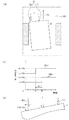
次に、図5を参照して、図3のS304における第一傾き量S1の検出動作を説明する。図5は、第一傾き量S1の検出動作の説明図である。図5(a)は、搬送路115上を搬送方向CDに搬送される原稿Dと原稿検出器109を示す図である。原稿検出器109は、搬送方向CDにおいて第一読取ユニット121および第二読取ユニット131の上流の搬送路115上に配置され、原稿が通過したか否かを検出する。本実施例の原稿検出器109は、搬送方向CDに垂直な方向に延在する軸(不図示)上に、距離Lだけ離れて配置された2つの原稿センサ400、401からなる。距離Lは、予めRAM204に保存されている。なお、原稿センサの数は、2つに限定されるものではなく3つ以上であってもよい。原稿センサ400、401は、原稿を検出するとHighレベル(以下、Hレベルという)の検出信号を出力し、原稿を検出しないとLowレベル(以下、Lレベルという)の検出信号を出力する。原稿センサ400、401は、搬送方向CDに搬送される原稿Dが原稿センサ400、401に到達する前は、Lレベルの検出信号を出力し、原稿Dの先端が原稿センサ400、401に到達すると、Hレベルの検出信号を出力する。原稿Dが原稿センサ400、401を通過している間、原稿センサ400、401は、Hレベルの検出信号を出力し続ける。原稿Dの後端が原稿センサ400、401を通過すると、原稿センサ400、401は、Lレベルの検出信号を出力する。
(Detection operation of the first tilt amount)
Next, the detection operation of the first inclination amount S1 in S304 of FIG. 3 will be described with reference to FIG. FIG. 5 is an explanatory diagram of the detection operation of the first inclination amount S1. FIG. 5A is a diagram showing a document D and a
図5(b)は、原稿センサ400から出力される検出信号400aと原稿センサ401から出力される検出信号401aのタイミング図である。図5(a)に示すように原稿Dが傾いて搬送された(斜行した)場合、図5(b)に示すように時刻t0で原稿センサ400の検出信号400aがLレベルからHレベルへ変化する。時刻t1で原稿センサ401の検出信号401aがLレベルからHレベルへ変化する。原稿センサ401の検出信号401aがLレベルからHレベルへ変化する時刻t1と原稿センサ400の検出信号400aがLレベルからHレベルへ変化する時刻t0との間に時間差Δtが生じる。
Δt=t1−t0
CPU203は、時間差ΔtをRAM204に保存する。
FIG. 5B is a timing diagram of the
Δt = t1-t0
The
図5(c)は、斜行した原稿Dの傾き角θの説明図である。原稿Dの傾き角θは、以下の式で表される。
tanθ=V×(t1−t0)/L
ここで、Vは、搬送方向CDにおける原稿Dの搬送速度である。搬送速度Vは、予めRAM204に保存されている。第一の傾き量検出手段としてのCPU203は、RAM204に保存された距離L、搬送速度Vおよび時間差Δtに基づいて正接tanθを算出する。本実施例において、上式の正接tanθを第一傾き量S1とする。
FIG. 5C is an explanatory diagram of the tilt angle θ of the oblique document D. The tilt angle θ of the document D is expressed by the following equation.
tan θ = V × (t1-t0) / L
Here, V is the transport speed of the document D in the transport direction CD. The transport speed V is stored in the
(第二傾き量の検出動作)
次に、図6、図7、図8および図9を参照して、図3のS306における第二傾き量S2の検出動作を説明する。なお、図3のS310における第三傾き量S3の検出動作は、第二傾き量S2の検出動作と同様であるので説明を省略する。図6は、CPU203により実行される第二傾き量S2の検出動作を示す流れ図である。図3のS306において第二傾き量S2の検出動作が開始されると、CPU203は、図6に示すようにエッジ検出画像を生成する(S501)。図7は、読取画像50とエッジ検出画像51を示す図である。S501において、CPU203は、RAM204から図7(a)に示す読取画像50を読み出し、図7(b)に示すエッジ検出画像51を生成する。CPU203は、エッジ検出画像51をRAM204に保存する。
(Detection operation of the second tilt amount)
Next, the detection operation of the second inclination amount S2 in S306 of FIG. 3 will be described with reference to FIGS. 6, 7, 8 and 9. Since the detection operation of the third inclination amount S3 in S310 of FIG. 3 is the same as the detection operation of the second inclination amount S2, the description thereof will be omitted. FIG. 6 is a flow chart showing a detection operation of the second inclination amount S2 executed by the
エッジ検出にはラプラシアンフィルタや微分フィルタなど様々な方法があるが、本実施例では副走査方向(搬送方向CD)に隣接する画素の輝度差を閾値と比較して判断する。注目画素の主走査座標をx、副走査座標をy、輝度値をB[x][y]と表した時、輝度差ΔB[x][y]は、
ΔB[x][y]=B[x][y+1]−B[x][y]
と表すことができる。輝度差ΔB[x][y]と閾値Bthを比較し、エッジ判定結果E[x][y]の値を決定する。本実施例では、ΔB[x][y]>Bthならエッジと判断してE[x][y]=1、ΔB[x][y]≦Bthなら非エッジと判断してE[x][y]=0とする。E[x][y]は、RAM204に保存される。
There are various methods for edge detection such as a Laplacian filter and a differential filter, but in this embodiment, the brightness difference between pixels adjacent to the sub-scanning direction (conveying direction CD) is determined by comparing with the threshold value. When the main scanning coordinates of the pixel of interest are x, the sub-scanning coordinates are y, and the luminance values are B [x] [y], the luminance difference ΔB [x] [y] is
ΔB [x] [y] = B [x] [y + 1] -B [x] [y]
It can be expressed as. The brightness difference ΔB [x] [y] is compared with the threshold value Bth to determine the value of the edge determination result E [x] [y]. In this embodiment, if ΔB [x] [y]> Bth, it is determined to be an edge and E [x] [y] = 1, and if ΔB [x] [y] ≤ Bth, it is determined to be non-edge and E [x]. [Y] = 0. E [x] and [y] are stored in the
CPU203は、RAM204からエッジ検出画像51を読み出し、原稿Dの先端座標を検出する(S502)。図8は、先端座標検出動作の説明図である。CPU203は、図8に示すように、主走査座標(主走査位置)x毎に副走査方向のy=0からy=y1の範囲内に、原稿の先端(以下、エッジということがある)があるか否か判定する。エッジがある場合、CPU203は、エッジの副走査座標yを先端座標格納配列edge[x]に格納する。
The
以下、図9を参照して、図6のS502における先端座標検出動作を説明する。図9は、CPU203により実行される先端座標検出動作を示す流れ図である。CPU203の主走査カウンタ211は、主走査座標xをカウントするので、主走査カウンタ211のカウント値をxで表す。CPU203の副走査カウンタ212は、副走査座標yをカウントするので、副走査カウンタ212のカウント値をyで表す。先端座標検出動作が開始されると、CPU203は、主走査カウンタ211のカウント値xを0に初期化する(S801)。CPU203は、副走査カウンタ212のカウント値yを0に初期化する(S802)。
Hereinafter, the tip coordinate detection operation in S502 of FIG. 6 will be described with reference to FIG. FIG. 9 is a flow chart showing a tip coordinate detection operation executed by the
CPU203は、座標(x,y)におけるエッジ判定結果E[x][y]が1であるか否かを判断する(S803)。座標(x,y)がエッジであると判断されると、エッジ判定結果E[x][y]が1になる。座標(x,y)がエッジでないと判断されると、エッジ判定結果E[x][y]が0にある。E[x][y]が1である場合(S803でYES)、CPU203は、先端座標格納配列edge[x]に副走査カウンタ212のカウント値yを格納する(S805)。処理は、S808へ進む。一方、E[x][y]が1でない場合(S803でNO)、CPU203は、副走査カウンタ212のカウント値yを1インクリメントする(S804)。CPU203は、副走査カウンタ212のカウント値yがエッジ検出範囲終了位置y1未満であるか否かを判断する(S806)。カウント値yがエッジ検出範囲終了位置y1未満である場合(S806でYES)、処理は、S803へ戻る。
The
カウント値yがエッジ検出範囲終了位置y1未満でない場合(S806でNO)、CPU203は、先端座標格納配列edge[x]に0を格納する(S807)。この結果、先端座標格納配列edge[x]が0である場合、主走査座標(主走査位置)xにおいて原稿の先端がy<y1の範囲に存在しない。CPU203は、主走査カウンタ211のカウント値xを1インクリメントする(S808)。CPU203は、主走査カウンタ211のカウント値xが主走査読取領域終了位置width未満であるか否かを判断する(S809)。カウント値xが主走査読取領域終了位置width未満である場合(S809でYES)、処理は、S802へ戻る。カウント値xが主走査読取領域終了位置width未満でない場合(S809でNO)、CPU203は、先端座標検出動作を終了する。処理は、図6のS503へ進む。
When the count value y is not less than the edge detection range end position y1 (NO in S806), the
第二の傾き量検出手段としてのCPU203は、S502で求めた先端座標格納配列edge[x]に基づいて、斜行した原稿Dの傾き角θを算出する(S503)。CPU203は、先端座標格納配列edge[x]に基づいて原稿の先端の回帰直線を求める。回帰直線の傾きが、傾き角θの正接tanθに相当する。本実施例では、回帰直線の傾きを第二傾き量S2とする。
The
回帰直線を求めるために、図8に示すように、先端座標格納配列edge[x]のうち、原稿Dの中央付近の主走査範囲701に含まれるデータのみを用いる。先端座標格納配列edge[x]が0であるデータは、回帰直線を求める計算に用いられない。また、先端座標格納配列edge[x]が0でないデータが主走査座標xの小さい方から所定数の画素が連続する範囲702は、回帰直線を求める計算に用いられない。また、先端座標格納配列edge[x]が0でないデータが主走査座標xの大きい方から所定数の画素が連続する範囲703は、回帰直線を求める計算に用いられない。これは、原稿Dの傾きに伴う原稿Dの量端のエッジを除外して回帰直線の算出精度を向上するためである。さらに、先端座標格納配列edge[x]の0が連続する部分において、離散的に現れる先端座標格納配列edge[x]が0でないデータの範囲704も、回帰直線を求める計算に用いられない。これは、ゴミによる回帰直線の算出精度の低下を防止するためである。
In order to obtain the regression line, as shown in FIG. 8, only the data included in the
(画像データの傾き補正および出力)
次に、図3のS315、S316、S318およびS320において実行される画像データの傾き補正および出力を説明する。CPU203は、決定された傾き補正量CSf又はCSbに基づいて、RAM204に保存された画像データに対してアフィン変換処理を行い、傾き補正された画像データを出力する。CPU203は、アフィン変換処理により読取画像50の傾きを補正し、補正された画像データを出力する。図10は、傾き補正された画像52を示す図である。図7(a)に示す読取画像50は、アフィン変換処理により画像データの傾きが補正され、図10に示す画像52として出力される。
(Inclination correction and output of image data)
Next, the tilt correction and output of the image data executed in S315, S316, S318 and S320 of FIG. 3 will be described. The
本実施例によれば、原稿の表面又は裏面の画像データに基づいて検出された第二傾き量S2又は第三傾き量S3に異常がある場合、原稿検出器109の検出結果に基づいて検出された第一傾き量S1に基づいて画像データの傾きを補正することができる。原稿の搬送方向CDの上流側の第一読取ユニット121の検出結果に基づく第二傾き量S2の信頼度が高い場合、下流側の第二読取ユニット131の検出結果に基づく第三傾き量S3を検出する前に、第二傾き量S2に基づいて原稿の傾き補正量が決定される。このように、原稿の表面又は裏面の画像データに基づいて検出された第二傾き量S2又は第三傾き量S3に誤りがある場合であっても、より正確な傾き補正量を検出することができる。
According to this embodiment, when there is an abnormality in the second tilt amount S2 or the third tilt amount S3 detected based on the image data of the front surface or the back surface of the document, it is detected based on the detection result of the
本実施例によれば、画像データの傾き補正の精度を向上し、原稿の画像の読み取り開始から画像データの取得までの時間を低減することができる。 According to this embodiment, it is possible to improve the accuracy of the tilt correction of the image data and reduce the time from the start of reading the image of the original to the acquisition of the image data.
(片面読取モード)
本実施例では、原稿の両面の画像を読み取る両面読取モードにおける傾き補正動作を説明したが、原稿の表面の画像のみを読み取る片面読取モードにおいても本発明を適用することができる。片面読取モードでは、図3のS308で第一の誤差値E1が第一の閾値Sth1より大きくない場合(S308でNO)、第二傾き量S2に基づいて表面の画像データの傾きが補正された後、裏面の画像の読み取りが開始されるが、S320はスキップされる。第一の誤差値E1が第一の閾値Sth1より大きい場合(S308でYES)、S313又はS314で決定された第一傾き量S1又は第三傾き量S3に基づいて表面の画像データの傾きが補正されるが、S316はスキップされる。片面読取モードにおいても原稿の傾き量を検出するために表裏両面の画像が読み取られるが、表面の画像データのみの傾き補正および出力が行われ、裏面の画像データの傾き補正および出力は行われない。
(Single-sided reading mode)
In this embodiment, the tilt correction operation in the double-sided scanning mode in which the images on both sides of the original are read has been described, but the present invention can also be applied in the single-sided scanning mode in which only the image on the surface of the original is read. In the single-sided reading mode, when the first error value E1 is not larger than the first threshold value Sth1 in S308 of FIG. 3 (NO in S308), the inclination of the image data on the surface is corrected based on the second inclination amount S2. Later, reading of the image on the back surface is started, but S320 is skipped. When the first error value E1 is larger than the first threshold value Sth1 (YES in S308), the inclination of the surface image data is corrected based on the first inclination amount S1 or the third inclination amount S3 determined in S313 or S314. However, S316 is skipped. Even in the single-sided scanning mode, the images on both the front and back sides are read to detect the amount of tilt of the document, but only the image data on the front side is corrected and output, and the image data on the back side is not tilt-corrected and output. ..
以下、実施例2を説明する。実施例1と同様の構造には、同様の参照符号を付して説明を省略する。実施例2の画像読取装置100、画像読取動作、信号処理基板200、傾き量補正動作、画像データ出力タイミングおよび第一傾き量の検出動作は、実施例1と同様であるので説明を省略する。実施例2は、図3のS306で第二傾き量S2を検出するために輝度差ΔB[x][y]と比較される第一の閾値Bth1がS310で第三傾き量S3を検出するために輝度差ΔB[x][y]と比較される第二の閾値Bth2と異なる点で、実施例1と異なる。以下、異なる点を主に説明する。
Hereinafter, the second embodiment will be described. The same structure as in the first embodiment is designated by the same reference numerals, and the description thereof will be omitted. The
第二傾き量S2又は第三傾き量S3の検出結果に異常が生じる場合、その原因の多くは、原稿の罫線を原稿の先端と誤って検出することである。原稿が薄い紙である場合、生成されたエッジ検出画像に原稿の先端がほとんど現れない。図11は、実施例2の読取画像60とエッジ検出画像61、62を示す図である。原稿が薄い紙である場合、図11(a)に示す読取画像60に基づいて、図11(b)に示すエッジ検出画像(第一のエッジ検出画像)61が生成されることがある。図11(b)に示すエッジ検出画像61には、原稿の先端が現れていないので、CPU203は、原稿の罫線を誤って原稿の先端であると判断する。この場合、原稿通過時刻に基づいて検出された第一傾き量S1とエッジ検出画像61に基づいて検出された第二傾き量S2の差としての第一の誤差値E1が第一の閾値Sth1より大きくなる。そのため、第二傾き量S2の信頼度が低いと判断され、原稿の裏面の画像データに基づいて第三傾き量S3の検出が行われる。
When an abnormality occurs in the detection result of the second inclination amount S2 or the third inclination amount S3, most of the causes are that the ruled line of the document is erroneously detected as the tip of the document. When the original is thin paper, the tip of the original hardly appears in the generated edge detection image. FIG. 11 is a diagram showing the scanned
しかし、第三傾き量S3の検出において、第二傾き量S2の検出で用いた第一の閾値Bth1と同じ閾値を用いると、生成されるエッジ検出画像に原稿の先端がほとんど現れないので、第三傾き量S3の検出結果に誤りを生じるおそれがある。そこで、第二傾き量S2の検出と第三傾き量S3の検出とで、閾値Bth(パラメータ)を変更する。第三傾き量S3の検出においては、薄い紙の先端を検出できるように第二の閾値Bth2(第二のパラメータ)を設定する。具体的には、第三傾き量S3の検出で用いる第二の閾値Bth2を、第二傾き量S2の検出で用いる第一の閾値Bth1(第一のパラメータ)より低い値に設定する。 However, if the same threshold value as the first threshold value Bth1 used in the detection of the second tilt amount S2 is used in the detection of the third tilt amount S3, the tip of the document hardly appears in the generated edge detection image. (3) There is a possibility that an error may occur in the detection result of the inclination amount S3. Therefore, the threshold value Bth (parameter) is changed between the detection of the second inclination amount S2 and the detection of the third inclination amount S3. In the detection of the third inclination amount S3, the second threshold value Bth2 (second parameter) is set so that the tip of the thin paper can be detected. Specifically, the second threshold value Bth2 used for detecting the third inclination amount S3 is set to a value lower than the first threshold value Bth1 (first parameter) used for detecting the second inclination amount S2.
第二傾き量S2の検出で用いられる第一の閾値Bth1を低い値に設定すると、ノイズや紙の模様等による誤検出のリスクが増大する。そこで、第二傾き量S2の検出で用いられる第一の閾値Bth1は、ノイズや紙の模様等による誤検出のリスクを低くすることができる値に設定される。一方、第二傾き量S2の検出結果の信頼度が低いと判断された場合、第三傾き量S3の検出では、ノイズや紙の模様等による誤検出のリスクを伴っても薄い紙の先端を検出可能な値に第二の閾値Bth2を設定する。第二の閾値Bth2を第一の閾値Bth1より低い値に設定して生成されたエッジ検出画像(第二のエッジ検出画像)62を図11(c)に示す。図11(b)に示すエッジ検出画像61では原稿の先端が検出しにくいが、図11(c)に示すエッジ検出画像62では原稿の先端が検出しやすい。
If the first threshold value Bth1 used for detecting the second inclination amount S2 is set to a low value, the risk of erroneous detection due to noise, paper patterns, or the like increases. Therefore, the first threshold value Bth1 used for detecting the second inclination amount S2 is set to a value that can reduce the risk of erroneous detection due to noise, paper patterns, or the like. On the other hand, when it is determined that the reliability of the detection result of the second inclination amount S2 is low, the tip of the thin paper is used in the detection of the third inclination amount S3 even if there is a risk of false detection due to noise or paper pattern. The second threshold value Bth2 is set to the detectable value. FIG. 11C shows an edge detection image (second edge detection image) 62 generated by setting the second threshold value Bth2 to a value lower than the first threshold value Bth1. The
図11(c)に示すエッジ検出画像62は、紙の模様やゴミ等のノイズを含んでいるが、原稿の外周の縁部が現れている。第三傾き量S3の検出動作においてノイズ等による誤検出が発生した場合、図3のS312およびS313で第一傾き量S1に基づいて傾き補正量が決定される。よって、ノイズや紙の模様等による誤検出のリスクを回避することができる。このように、本実施例によれば、原稿が薄紙であっても、画像データの傾き補正の精度を向上させることができる。従って、原稿の表面又は裏面の画像データに基づいて検出された第二傾き量S2又は第三傾き量S3に誤りがある場合であっても、より正確な傾き補正量を検出することができる。
The
本実施例によれば、画像データの傾き補正の精度を向上し、原稿の画像の読み取り開始から画像データの取得までの時間を低減することができる。 According to this embodiment, it is possible to improve the accuracy of the tilt correction of the image data and reduce the time from the start of reading the image of the original to the acquisition of the image data.
100・・・画像読取装置
102・・・ADF(原稿搬送手段)
109・・・原稿検出器(原稿検出手段)
121・・・第一読取ユニット(第一の画像読取手段)
131・・・第一読取ユニット(第二の画像読取手段)
203・・・CPU(第一の傾き量検出手段、第二の傾き量検出手段、第三の傾き量検出手段、傾き補正量決定手段)
100 ...
109 ... Original detector (Original detection means)
121 ... First reading unit (first image reading means)
131 ... First reading unit (second image reading means)
203 ... CPU (first tilt amount detecting means, second tilt amount detecting means, third tilt amount detecting means, tilt correction amount determining means)
Claims (5)
前記原稿搬送手段により搬送される前記原稿の第一の面の画像を読み取る第一の画像読取手段と、
前記原稿が搬送される搬送方向において前記第一の画像読取手段の下流に配置され、前記原稿搬送手段により搬送される前記原稿の前記第一の面とは反対の第二の面の画像を読み取る第二の画像読取手段と、
前記搬送方向において前記第一の画像読取手段の上流に配置され、前記原稿搬送手段により搬送される前記原稿を検出する第一の原稿検出手段と、
前記搬送方向において前記第一の画像読取手段の上流且つ前記搬送方向に垂直な幅方向において前記第一の原稿検出手段とは異なる位置に配置され、前記原稿搬送手段により搬送される前記原稿を検出する第二の原稿検出手段と、
前記第一の原稿検出手段が前記原稿を検出したタイミングと前記第二の原稿検出手段が前記原稿を検出したタイミングとに基づいて前記原稿の第一傾き量を検出する第一の傾き量検出手段と、
前記第一の画像読取手段により読み取られた前記第一の面の画像を表す画像データに基づいて前記原稿の第二傾き量を検出する第二の傾き量検出手段と、
前記第二の画像読取手段により読み取られた前記第二の面の画像を表す画像データに基づいて前記原稿の第三傾き量を検出する第三の傾き量検出手段と、
前記第一傾き量と前記第二傾き量との差の絶対値が第一の所定値以下である場合は前記第一の面の前記画像データの傾きを補正するための第一の傾き補正量及び前記第二の面の前記画像データの傾きを補正するための第二の傾き補正量を前記第二傾き量に基づいて決定し、前記第一傾き量と前記第二傾き量との差の絶対値が前記第一の所定値より大きい場合は前記第一の傾き補正量及び前記第二の傾き補正量を前記第一傾き量と前記第三傾き量とに基づいて決定する傾き補正量決定手段と、
前記傾き補正量決定手段によって決定された補正量に基づいて、前記第一の面の前記画像データの傾き及び前記第二の面の前記画像データの傾きを補正する補正手段と、
を備えることを特徴とする画像読取装置。 Document transport means for transporting documents and
A first image reading means for reading an image of the first surface of the document conveyed by the document conveying means, and
The document is arranged downstream of the first image reading means in the conveying direction is conveyed to read an image of the opposite second surface from said first surface of said original conveyed by said original conveying means The second image reading means,
A first document detecting means, which is arranged upstream of the first image reading means in the transport direction and detects the document transported by the document transporting means, and a first document detecting means.
The document is located upstream of the first image reading means in the transport direction and at a position different from that of the first document detecting means in the width direction perpendicular to the transport direction, and detects the document transported by the document transporting means. Second document detection means to be
The first tilt amount detecting means for detecting the first tilt amount of the document based on the timing when the first document detecting means detects the document and the timing when the second document detecting means detects the document. When,
A second tilt amount detecting means for detecting the second tilt amount of the document based on image data representing the image of the first surface read by the first image reading means, and a second tilt amount detecting means.
A third tilt amount detecting means for detecting the third tilt amount of the document based on image data representing the image of the second surface read by the second image reading means, and a third tilt amount detecting means.
Absolute value first inclination correction for correcting a tilt of the image data of the first is less than or equal to the predetermined value before Symbol first aspect of the difference between the second tilt amount and the first amount of inclination The amount and the second tilt correction amount for correcting the tilt of the image data on the second surface are determined based on the second tilt amount, and the difference between the first tilt amount and the second tilt amount. absolute value tilt correction if greater than said first predetermined value is determined based pre Symbol first inclination correction amount and the second inclination correction amount and the third amount of inclination between the first inclination amount of Quantitative means and
A correction means for correcting the inclination of the image data on the first surface and the inclination of the image data on the second surface based on the correction amount determined by the inclination correction amount determining means.
An image reading device comprising.
前記第三の傾き量検出手段は、前記第二の面の前記画像データに基づいて検出された前記原稿のエッジに基づいて前記第三傾き量を検出することを特徴とする請求項1乃至4のいずれか一項に記載の画像読取装置。 The second tilt amount detecting means detects the second tilt amount based on the edge of the document detected based on the image data of the first surface.
Claims 1 to 4, wherein the third tilt amount detecting means detects the third tilt amount based on the edge of the document detected based on the image data of the second surface. The image reading device according to any one of the above.
Priority Applications (1)
| Application Number | Priority Date | Filing Date | Title |
|---|---|---|---|
| JP2017117483A JP6905393B2 (en) | 2017-06-15 | 2017-06-15 | Image reader |
Applications Claiming Priority (1)
| Application Number | Priority Date | Filing Date | Title |
|---|---|---|---|
| JP2017117483A JP6905393B2 (en) | 2017-06-15 | 2017-06-15 | Image reader |
Publications (3)
| Publication Number | Publication Date |
|---|---|
| JP2019004314A JP2019004314A (en) | 2019-01-10 |
| JP2019004314A5 JP2019004314A5 (en) | 2020-07-27 |
| JP6905393B2 true JP6905393B2 (en) | 2021-07-21 |
Family
ID=65006235
Family Applications (1)
| Application Number | Title | Priority Date | Filing Date |
|---|---|---|---|
| JP2017117483A Active JP6905393B2 (en) | 2017-06-15 | 2017-06-15 | Image reader |
Country Status (1)
| Country | Link |
|---|---|
| JP (1) | JP6905393B2 (en) |
Families Citing this family (1)
| Publication number | Priority date | Publication date | Assignee | Title |
|---|---|---|---|---|
| JP7259635B2 (en) * | 2019-08-16 | 2023-04-18 | コニカミノルタ株式会社 | Image reading device, image forming device and program |
Family Cites Families (1)
| Publication number | Priority date | Publication date | Assignee | Title |
|---|---|---|---|---|
| JP5376907B2 (en) * | 2008-11-13 | 2013-12-25 | キヤノン株式会社 | Image reading apparatus and image processing method |
-
2017
- 2017-06-15 JP JP2017117483A patent/JP6905393B2/en active Active
Also Published As
| Publication number | Publication date |
|---|---|
| JP2019004314A (en) | 2019-01-10 |
Similar Documents
| Publication | Publication Date | Title |
|---|---|---|
| US11102364B2 (en) | Inclination detecting device, reading device, image processing apparatus, and method of detecting inclination | |
| US10129415B2 (en) | Image reading apparatus, image forming apparatus, image reading method, and storage medium | |
| JP6671927B2 (en) | Image reading apparatus and image reading method | |
| CN111510573B (en) | Tilt detection device, reading device, image processing device, and tilt detection method | |
| US8670163B2 (en) | Image reader and image forming apparatus using same using multiple image sensors and which corrects misalignment | |
| US10491770B2 (en) | Image reading apparatus with skew feed correction and image reading method thereof | |
| US9237256B2 (en) | Document reading apparatus and image processing method | |
| US10356252B2 (en) | Image reading apparatus, image forming apparatus, image reading method, and non-transitory storage medium that generate abnormal pixel information based on received information | |
| JP7211238B2 (en) | Edge detection device, tilt correction device, reading device, image processing device, and edge detection method | |
| JP5390418B2 (en) | Image reading apparatus and image reading system | |
| JP7341808B2 (en) | Image reading device and its control method | |
| JP5683099B2 (en) | Image reading apparatus, image reading apparatus control method, and program | |
| US11190658B2 (en) | Image reading apparatus | |
| US10389911B2 (en) | Original reading apparatus | |
| JP6905393B2 (en) | Image reader | |
| US20210144273A1 (en) | Image reading apparatus | |
| US9811767B2 (en) | Image processing apparatus, image processing method and program | |
| JP2021042068A (en) | Medium conveyance device, control method and control program | |
| US20220345586A1 (en) | Image reading apparatus, control method thereof, and storage medium | |
| JP3417723B2 (en) | Image reading device | |
| US9699327B2 (en) | Image reading apparatus capable of determining reading position less affected by foreign matter | |
| JP2019068132A (en) | Image reading apparatus and image reading method | |
| US11891266B2 (en) | Medium conveying apparatus to determine whether multi-feed has occurred based on whether outer shape of object area in input image is rectangular | |
| US12081710B2 (en) | Image reading device and image reading method | |
| US20210400158A1 (en) | Medium conveying apparatus for controlling medium conveyance based on inclination of medium and position of medium |
Legal Events
| Date | Code | Title | Description |
|---|---|---|---|
| RD05 | Notification of revocation of power of attorney |
Free format text: JAPANESE INTERMEDIATE CODE: A7425 Effective date: 20171214 |
|
| RD04 | Notification of resignation of power of attorney |
Free format text: JAPANESE INTERMEDIATE CODE: A7424 Effective date: 20180126 |
|
| A521 | Written amendment |
Free format text: JAPANESE INTERMEDIATE CODE: A523 Effective date: 20200605 |
|
| A621 | Written request for application examination |
Free format text: JAPANESE INTERMEDIATE CODE: A621 Effective date: 20200605 |
|
| A977 | Report on retrieval |
Free format text: JAPANESE INTERMEDIATE CODE: A971007 Effective date: 20210325 |
|
| A131 | Notification of reasons for refusal |
Free format text: JAPANESE INTERMEDIATE CODE: A131 Effective date: 20210408 |
|
| A521 | Written amendment |
Free format text: JAPANESE INTERMEDIATE CODE: A523 Effective date: 20210511 |
|
| TRDD | Decision of grant or rejection written | ||
| A01 | Written decision to grant a patent or to grant a registration (utility model) |
Free format text: JAPANESE INTERMEDIATE CODE: A01 Effective date: 20210527 |
|
| A61 | First payment of annual fees (during grant procedure) |
Free format text: JAPANESE INTERMEDIATE CODE: A61 Effective date: 20210625 |
|
| R151 | Written notification of patent or utility model registration |
Ref document number: 6905393 Country of ref document: JP Free format text: JAPANESE INTERMEDIATE CODE: R151 |