JP2007243631A - Head-mounted display device - Google Patents
Head-mounted display device Download PDFInfo
- Publication number
- JP2007243631A JP2007243631A JP2006063625A JP2006063625A JP2007243631A JP 2007243631 A JP2007243631 A JP 2007243631A JP 2006063625 A JP2006063625 A JP 2006063625A JP 2006063625 A JP2006063625 A JP 2006063625A JP 2007243631 A JP2007243631 A JP 2007243631A
- Authority
- JP
- Japan
- Prior art keywords
- arm
- head
- display device
- mounted display
- auxiliary
- Prior art date
- Legal status (The legal status is an assumption and is not a legal conclusion. Google has not performed a legal analysis and makes no representation as to the accuracy of the status listed.)
- Withdrawn
Links
Images

Abstract
Description
この発明はヘッドマウントディスプレイ装置に関する。 The present invention relates to a head mounted display device.
従来、リアアームと2つのヘッドホン部とフロントアームと支持部材とを備えるヘッドマウントディスプレイ装置が知られている(下記特許文献1参照)。 Conventionally, a head mounted display device including a rear arm, two headphone units, a front arm, and a support member is known (see Patent Document 1 below).
このヘッドマウントディスプレイでは、2つのヘッドホン部にそれぞれ耳掛け部が設けられている。 In this head mounted display, the earphones are respectively provided in the two headphones.
この耳掛け部を耳に掛けることによって、ヘッドマウントディスプレイ装置は頭部に装着される。
従来のヘッドマウントディスプレイ装置では、上述のように、耳掛け部を耳に掛けることによってヘッドマウントディスプレイ装置を頭部に装着する構成が採用されているので、頭部が動くとヘッドマウントディスプレイ装置が耳掛け部を中心にして回転し易かった。 In the conventional head-mounted display device, as described above, a configuration in which the head-mounted display device is mounted on the head by putting the ear hook on the ear is employed. It was easy to rotate around the ear hook.
このため、映像表示部が上下方向へぶれ、映像を見難くなる虞があった。 For this reason, there is a possibility that the video display unit may be moved up and down, making it difficult to view the video.
この発明はこのような事情に鑑みてなされたもので、その課題は、表示手段のぶれが少ないヘッドマウントディスプレイ装置を提供することである。 The present invention has been made in view of such circumstances, and an object of the present invention is to provide a head-mounted display device in which display means is less blurred.
前述の課題を解決するため請求項1の発明のヘッドマウントディスプレイ装置は、頭部に装着されるリアアームと、前記リアアームの両端部に設けられ、左右の耳に装着される2つのサイド部材と、目の前方に表示手段を支持するための支持アームと、前記2つのサイド部材のうちの少なくとも一方のサイド部材に前記支持アームを連結する連結手段とを備えているヘッドマウントディスプレイ装置において、前記2つのサイド部材のうちの少なくとも一方のサイド部材に前記2つのサイド部材を結ぶ仮想軸周りへ回転可能に設けられ、前記頭部に装着される補助アームを備えていることを特徴とする。 In order to solve the above-mentioned problem, a head-mounted display device according to the invention of claim 1 includes a rear arm to be mounted on the head, two side members provided at both ends of the rear arm and mounted to the left and right ears, In the head mounted display device comprising: a support arm for supporting the display means in front of the eye; and a connecting means for connecting the support arm to at least one of the two side members. An auxiliary arm mounted on the head is provided to be rotatable about a virtual axis connecting the two side members to at least one side member of the two side members.
請求項2の発明は、請求項1記載のヘッドマウントディスプレイ装置において、前記補助アームの両端部が前記2つのサイド部材に回転可能に支持される両持ち型であることを特徴とする。 According to a second aspect of the present invention, in the head mounted display device according to the first aspect, the both ends of the auxiliary arm are of a double-supported type that is rotatably supported by the two side members.
請求項3の発明は、請求項2記載のヘッドマウントディスプレイ装置において、前記補助アームが1つであることを特徴とする。 According to a third aspect of the present invention, in the head mounted display device according to the second aspect, the number of the auxiliary arms is one.
請求項4の発明は、請求項2記載のヘッドマウントディスプレイ装置において、前記補助アームが複数あることを特徴とする。 According to a fourth aspect of the present invention, there is provided the head mounted display device according to the second aspect, wherein a plurality of the auxiliary arms are provided.
請求項5の発明は、請求項1記載のヘッドマウントディスプレイ装置において、前記補助アームの一端部が前記2つのサイド部材のうちの一方のサイド部材に回転可能に支持される片持ち型であることを特徴とする。 According to a fifth aspect of the present invention, in the head mounted display device according to the first aspect, the one end portion of the auxiliary arm is a cantilever type rotatably supported by one of the two side members. It is characterized by.
請求項6の発明は、請求項5記載のヘッドマウントディスプレイ装置において、前記補助アームが1つであることを特徴とする。 According to a sixth aspect of the present invention, in the head mounted display device according to the fifth aspect, the number of the auxiliary arms is one.
請求項7の発明は、請求項5記載のヘッドマウントディスプレイ装置において、前記補助アームが複数あることを特徴とする。 A seventh aspect of the invention is the head-mounted display device according to the fifth aspect, wherein a plurality of the auxiliary arms are provided.
請求項8の発明は、請求項1〜7のいずれか1項記載のヘッドマウントディスプレイ装置において、前記補助アームのほぼ全体が前記リアアームにほぼ重なるアーム不使用位置から前記補助アームの一部が前記頭部の頂部側へ所定角度回転したアーム使用位置までの任意の回転位置に前記補助アームを固定させるロック手段を備えていることを特徴とする。 According to an eighth aspect of the present invention, in the head mounted display device according to any one of the first to seventh aspects, a part of the auxiliary arm is moved from an arm non-use position where substantially the entire auxiliary arm substantially overlaps the rear arm. Locking means for fixing the auxiliary arm to an arbitrary rotation position up to an arm use position rotated by a predetermined angle toward the top of the head is provided.
この発明によれば、表示手段のぶれが少ないヘッドマウントディスプレイを提供することができる。 According to the present invention, it is possible to provide a head-mounted display with less display means shaking.
以下、この発明の実施の形態を図面に基づいて説明する。 Hereinafter, embodiments of the present invention will be described with reference to the drawings.
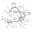
図1はこの発明の第1の実施形態に係るヘッドマウントディスプレイ装置の斜視図、図2は図1に示すヘッドマウントディスプレイの側面図である。 FIG. 1 is a perspective view of a head mounted display device according to a first embodiment of the present invention, and FIG. 2 is a side view of the head mounted display shown in FIG.
図1、2に示すように、このヘッドマウントディスプレイ装置はリアアーム3と2つのヘッドホン部(サイド部材)4,5と映像表示部(表示手段)6とフロントアーム(支持アーム)7と支持部材(連結手段)8と補助アーム11とを備える。
As shown in FIGS. 1 and 2, the head mounted display device includes a
リアアーム3は使用者Hの後頭部に装着される。リアアーム3はリアアーム本体3Aと連結部3Bとを有する。リアアーム本体3AはU字状に形成され、弾性を有する。連結部3Bはほぼリング状であり、リアアーム本体3Aの両端部に設けられている。
The
ヘッドホン部4は使用者Hの左の耳に装着され、ヘッドホン部5は使用者Hの右の耳に装着される。ヘッドホン部4,5はリアアーム本体3Aの弾力によって使用者Hの側頭部に押し付けられる。
The
映像表示部6はフロントアーム7の一端に取り付けられている。
The
フロントアーム7は映像表示部6を左目の前方に位置するように映像表示部6を支持する。
The
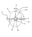
支持部材8は有底円筒状であり、フロントアーム7を前後方向D1へ移動可能に、且つ着脱可能に支持する。支持部材8の一端部はリアアーム3の連結部3Bに挿入され、固定されている。また、支持部材8の一端部はヘッドホン部4のケーシング41に回転可能に連結されている。したがって、リアアーム3の一端部は支持部材8を介してヘッドホン部4に回転可能に連結されていることになる。リアアーム3の他端部も支持部材8によってヘッドホン部5に回転可能に連結されている。したがって、リアアーム3は2つのヘッドホン部4,5を結ぶ仮想軸O1周りへ回転可能である。
The
補助アーム11は補助アーム本体11Aと連結部11Bとを有する。補助アーム本体11AはU字状に形成され、弾性を有する。連結部11Bはほぼリング状であり、補助アーム本体3Aの両端部に設けられている。補助アーム11の一方の連結部11Bはリアアーム3の連結部3Bとヘッドホン部4のケーシング41との間に配置されるように、支持部材8に回転可能に装着されている。補助アーム11の他方の連結部11Bは一方の連結部11B同様に支持部材8に回転可能に装着されている。これにより、補助アーム11は、図1中の矢印Aで示すように、仮想軸O1周りへ回転可能である。
The
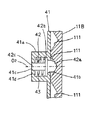
図3は図1に示すヘッドマウントディスプレイのロック機構の断面図である。 3 is a cross-sectional view of the lock mechanism of the head mounted display shown in FIG.
図3に示すように、ヘッドホン部4のケーシング41はロック部材収容部41aを有する。ロック部材収容部41aには第1の孔41bと第2の孔41cとが形成されている。
As shown in FIG. 3, the
ロック部材収容部41a内にはロック部材42が収容されている。ロック部材42は係止部42aと鍔部42bとピン状部42cとを有する。係止部42aは第1の孔41bを通じてロック部材収容部41aの外へ突出する。鍔部42bは係止部42aに結合され、係止部42aが第1の孔41bから脱落するのを防止するとともに後述するばね43のばね力を受ける。ピン状部42cは鍔部42bに結合され、第2の孔41cに軸方向O2へ摺動可能に挿入されている。これにより、係止部42は軸方向O2へ案内される。軸方向O2は仮想軸O1から偏心している。鍔部42bとロック部材収容部41aの底部41dとの間にはばね43が配置されている。ばね43は鍔部42bを補助アーム11の連結部11Bの方へ常時押圧する。
A
補助アーム11の連結部11Bには周方向へ所定間隔に複数の係合凹部111が形成されている。係合凹部111はロック部材42の係止部42aを受け止める。
A plurality of
ロック部材収容部41aとロック部材42とばね43と係合凹部111とで、ロック機構(ロック手段)が構成されている。このロック機構は、補助アーム11の全体がリアアーム3に重なる補助アーム不使用位置(図2中点線で示す位置)から補助アーム11の一部が使用者Hの頭部の頂部側へ所定角度(例えば90°)回転した補助アーム使用位置(図2中実線で示す位置)までの任意の回転位置に補助アーム11を固定させる。
The lock
この実施形態のヘッドマウントディスプレイ装置の使用に際しては、図1、2に示すように、予め補助アーム11が頭部の頂部に来るように補助アーム11を回転させ、この状態でヘッドマウントディスプレイ装置を頭部に装着すればよい。
When using the head mounted display device of this embodiment, as shown in FIGS. 1 and 2, the
ヘッドマウントディスプレイ装置を頭部に装着後、映像表示部6を前後方向D1に沿って動かし、映像表示部6を見やすい所に移動する。
After mounting the head-mounted display device on the head, the
映像表示部6を使用しない場合、補助アーム11をリアアーム3の方へ回転させて、図2中の点線で示すように、リアアーム3と後頭部との間に収める。
When the
この実施形態によれば、補助アーム11が使用者Hの耳から離れた位置で頭部と接するので、ヘッドホン部4,5がぐらつき難く、頭部が動いても映像表示部6のぶれを抑制することができる。
According to this embodiment, since the
また、映像表示部6を使用しない場合は、補助アーム11を回転させて、リアアーム3と後頭部との間に収めておくことができ、補助アーム11が邪魔にならない。
When the
更に、図1に示す状態から補助アーム11をほぼ180°回転させて、ヘッドマウントディスプレイ装置を頭部に装着すれば、右目で映像表示部6を見ることができる。
Further, when the
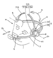
図4はこの発明の第2の実施形態に係るヘッドマウントディスプレイ装置の側面図である。 FIG. 4 is a side view of a head mounted display device according to the second embodiment of the present invention.
第1実施形態に係るヘッドマウントディスプレイ装置と共通する部分については、同一符号を付してその説明を省略する。以下、主な相違部分についてだけ説明する。 Portions common to the head mounted display device according to the first embodiment are denoted by the same reference numerals, and description thereof is omitted. Only the main differences will be described below.
第1実施形態に係るヘッドマウントディスプレイ装置では、補助アーム11が1つであるが、第2実施形態に係るヘッドマウントディプレイ装置では、第1補助アーム213と第2補助アーム214とが採用されている。第1、第2補助アーム213,214は第1実施形態と同様にヘッドホン部4,5に回転可能に取り付けられている。
In the head mounted display device according to the first embodiment, there is one
第1、第2補助アーム213,214を、図4中の点線で示すように、リアアーム3と後頭部との間に収めることができる。
The first and second
第2実施形態によれば、第1実施形態と同様の効果を奏するとともに、第1実施形態に較べ、頭部と接触する補助アーム213,214の数が多いので、映像表示部6のぶれをより抑制することができる。
According to the second embodiment, the same effect as that of the first embodiment can be obtained, and the number of
図5はこの発明の第3の実施形態に係るヘッドマウントディスプレイ装置の斜視図である。 FIG. 5 is a perspective view of a head mounted display device according to a third embodiment of the present invention.
第1、第2実施形態のヘッドマウントディスプレイ装置の補助アーム11,213,214は2つのヘッドホン部4,5に回転可能に支持される両持ち型であるが、第3実施形態のヘッドマウントディスプレイ装置の第1、第2補助アーム315、316は片方のヘッドホン部に支持される片持ち型である。第1補助アーム315はヘッドホン部4に、第2補助アーム316はヘッドホン部5にそれぞれ回転可能に支持されている。
The
第3実施形態によれば、第1実施形態と同様の効果を奏するとともに、装着感がよく、更に、髪の毛が乱れ難いという効果を奏する。 According to 3rd Embodiment, while there exists an effect similar to 1st Embodiment, there exists an effect that a feeling of mounting | wearing is good and hair is not easily disturbed.
なお、第1〜第3実施形態のヘッドマウントディスプレイ装置では、補助アーム11,213,214,315,316とリアアーム3とが前後方向D1で重なるが、補助アーム11,213,214,315,316とリアアーム3とが上下方向で重なるような構成を採用してもよい。
In the head mounted display devices of the first to third embodiments, the
また、リアアーム3に溝を形成し、この溝に補助アーム11,213,214,315,316を収容するようにしてもよい。
Further, a groove may be formed in the
なお、第1〜第3実施形態では、補助アーム11,213,214,315,316とリアアーム3とを重ねた場合、補助アーム11,213,214,315,316がリアアーム3の内側に配置されるが、補助アーム11,213,214,315,316がリアアーム3の外側に配置されるような構成を採用してもよい。
In the first to third embodiments, when the
また、ロック機構の代わりに公知の摩擦機構を用いるようにしてもよい。 A known friction mechanism may be used instead of the lock mechanism.
なお、第2実施形態において、第1補助アーム213と第2補助アーム214とを蛇腹状の部材で連結してもよい。
In the second embodiment, the first
また、第2実施形態において、図4に示すように、第1、第2補助アーム213,214を左目で映像表示部6を見るときの補助アームとして用いたが、これに代え、第1補助アーム213を左目で映像表示部6を見るときの補助アームとして用い、第2補助アーム214を右目で映像表示部6を見るときの補助アームとして用いるようにしてもよい。
In the second embodiment, as shown in FIG. 4, the first and second
3:リアアーム、4,5:ヘッドホン部(サイド部材)、6:映像表示部(表示手段)、7:フロントアーム(支持アーム)、8:支持部材(連結手段)、11,213,214,315,316:補助アーム、41a:ロック部材収容部、42:ロック部材、43:ばね、111:係合凹部、O1:仮想軸。 3: rear arm, 4, 5: headphone part (side member), 6: video display part (display means), 7: front arm (support arm), 8: support member (connecting means), 11, 213, 214, 315 316: Auxiliary arm, 41a: Lock member accommodating portion, 42: Lock member, 43: Spring, 111: Engaging recess, O1: Virtual axis.
Claims (8)
前記リアアームの両端部に設けられ、左右の耳に装着される2つのサイド部材と、
目の前方に表示手段を支持するための支持アームと、
前記2つのサイド部材のうちの少なくとも一方のサイド部材に前記支持アームを連結する連結手段とを備えているヘッドマウントディスプレイ装置において、
前記2つのサイド部材のうちの少なくとも一方のサイド部材に前記2つのサイド部材を結ぶ仮想軸周りへ回転可能に設けられ、前記頭部に装着される補助アーム
を備えていることを特徴とするヘッドマウントディスプレイ装置。 A rear arm attached to the head;
Two side members provided at both ends of the rear arm and attached to the left and right ears;
A support arm for supporting the display means in front of the eyes;
In a head mounted display device comprising a connecting means for connecting the support arm to at least one side member of the two side members,
A head comprising: an auxiliary arm that is provided to be rotatable about an imaginary axis connecting the two side members to at least one side member of the two side members, and is attached to the head. Mount display device.
Priority Applications (1)
| Application Number | Priority Date | Filing Date | Title |
|---|---|---|---|
| JP2006063625A JP2007243631A (en) | 2006-03-09 | 2006-03-09 | Head-mounted display device |
Applications Claiming Priority (1)
| Application Number | Priority Date | Filing Date | Title |
|---|---|---|---|
| JP2006063625A JP2007243631A (en) | 2006-03-09 | 2006-03-09 | Head-mounted display device |
Publications (1)
| Publication Number | Publication Date |
|---|---|
| JP2007243631A true JP2007243631A (en) | 2007-09-20 |
Family
ID=38588709
Family Applications (1)
| Application Number | Title | Priority Date | Filing Date |
|---|---|---|---|
| JP2006063625A Withdrawn JP2007243631A (en) | 2006-03-09 | 2006-03-09 | Head-mounted display device |
Country Status (1)
| Country | Link |
|---|---|
| JP (1) | JP2007243631A (en) |
Cited By (9)
| Publication number | Priority date | Publication date | Assignee | Title |
|---|---|---|---|---|
| WO2015003644A1 (en) * | 2013-07-12 | 2015-01-15 | Huang Tongbing | Easily stored speaker connecting device and novel eyeglass-type device |
| JP2016054351A (en) * | 2014-09-02 | 2016-04-14 | 株式会社Jvcケンウッド | Head-mounted display |
| JP2016054350A (en) * | 2014-09-02 | 2016-04-14 | 株式会社Jvcケンウッド | Head band and head mounted device |
| CN105829950A (en) * | 2015-08-19 | 2016-08-03 | 深圳市柔宇科技有限公司 | Wearable display device |
| WO2017045110A1 (en) * | 2015-09-14 | 2017-03-23 | 深圳市柔宇科技有限公司 | Head mounted display apparatus |
| US9900695B2 (en) | 2015-08-19 | 2018-02-20 | Shenzhen Royole Technologies Co. Ltd. | Head-mounted electronic device |
| US10042168B2 (en) | 2015-08-19 | 2018-08-07 | Shenzhen Royole Technologies Co., Ltd. | Head-mounted electronic device |
| JP2018526907A (en) * | 2015-08-19 | 2018-09-13 | シェンジェン ロイオル テクノロジーズ カンパニー リミテッドShenzhen Royole Technologies Co., Ltd. | Head mounted electronic device |
| WO2019090458A1 (en) * | 2017-11-07 | 2019-05-16 | 深圳市柔宇科技有限公司 | Head-mounted display device |
-
2006
- 2006-03-09 JP JP2006063625A patent/JP2007243631A/en not_active Withdrawn
Cited By (12)
| Publication number | Priority date | Publication date | Assignee | Title |
|---|---|---|---|---|
| WO2015003644A1 (en) * | 2013-07-12 | 2015-01-15 | Huang Tongbing | Easily stored speaker connecting device and novel eyeglass-type device |
| JP2016054351A (en) * | 2014-09-02 | 2016-04-14 | 株式会社Jvcケンウッド | Head-mounted display |
| JP2016054350A (en) * | 2014-09-02 | 2016-04-14 | 株式会社Jvcケンウッド | Head band and head mounted device |
| CN105829950A (en) * | 2015-08-19 | 2016-08-03 | 深圳市柔宇科技有限公司 | Wearable display device |
| US9900695B2 (en) | 2015-08-19 | 2018-02-20 | Shenzhen Royole Technologies Co. Ltd. | Head-mounted electronic device |
| US10042168B2 (en) | 2015-08-19 | 2018-08-07 | Shenzhen Royole Technologies Co., Ltd. | Head-mounted electronic device |
| JP2018526907A (en) * | 2015-08-19 | 2018-09-13 | シェンジェン ロイオル テクノロジーズ カンパニー リミテッドShenzhen Royole Technologies Co., Ltd. | Head mounted electronic device |
| US10095037B2 (en) | 2015-08-19 | 2018-10-09 | Shenzhen Royole Technologies Co., Ltd. | Head mounted electronic device |
| US10390127B2 (en) | 2015-08-19 | 2019-08-20 | Shenzhen Royole Technologies Co. Ltd. | Wearable display equipment |
| WO2017045110A1 (en) * | 2015-09-14 | 2017-03-23 | 深圳市柔宇科技有限公司 | Head mounted display apparatus |
| US9864200B2 (en) | 2015-09-14 | 2018-01-09 | Shenzhen Royole Technologies Co. Ltd. | Head-mounted display |
| WO2019090458A1 (en) * | 2017-11-07 | 2019-05-16 | 深圳市柔宇科技有限公司 | Head-mounted display device |
Similar Documents
| Publication | Publication Date | Title |
|---|---|---|
| JP2007243631A (en) | Head-mounted display device | |
| EP3351995B1 (en) | Head mounted display apparatus | |
| CN107533222B (en) | Head-mounted electronic device | |
| JP2010166258A (en) | Headphone and earmuffs | |
| CN106662744B (en) | Compact folding structure for head mounted equipment | |
| CN107003515B (en) | Head-mounted electronic device | |
| JP2009171303A (en) | Headphone | |
| WO2017028282A1 (en) | Wearable display device | |
| JP2009055122A (en) | Headphone device | |
| JP2018010117A (en) | Camera, stand, and camera unit provided with them | |
| JP5281436B2 (en) | earphone | |
| JP2012022018A (en) | Stereoscopic display device | |
| JP2016102542A (en) | Electronic apparatus | |
| KR101254468B1 (en) | Head-set for mounting camera module | |
| JP2015082824A (en) | Earphone | |
| JP6601689B2 (en) | Bone conduction headset | |
| JP2008022236A (en) | Head mount display | |
| JP6458821B2 (en) | Head mounted display | |
| JP2016102543A (en) | Elevation angle adjustment mechanism, rotation angle adjustment mechanism, and electronic apparatus | |
| JP7387468B2 (en) | head mounted display | |
| JP2014119722A (en) | Camera holder | |
| JP5917086B2 (en) | Imaging device, grip and imaging system | |
| JP2008147744A (en) | Output device | |
| JPWO2014041611A1 (en) | Electronics | |
| WO2021241633A1 (en) | Camera unit |
Legal Events
| Date | Code | Title | Description |
|---|---|---|---|
| A300 | Withdrawal of application because of no request for examination |
Free format text: JAPANESE INTERMEDIATE CODE: A300 Effective date: 20090512 |