WO2017045110A1 - Head mounted display apparatus - Google Patents
Head mounted display apparatus Download PDFInfo
- Publication number
- WO2017045110A1 WO2017045110A1 PCT/CN2015/089564 CN2015089564W WO2017045110A1 WO 2017045110 A1 WO2017045110 A1 WO 2017045110A1 CN 2015089564 W CN2015089564 W CN 2015089564W WO 2017045110 A1 WO2017045110 A1 WO 2017045110A1
- Authority
- WO
- WIPO (PCT)
- Prior art keywords
- rotating member
- display device
- head
- mounted display
- engaging
- Prior art date
Links
Images


Classifications
-
- G—PHYSICS
- G02—OPTICS
- G02B—OPTICAL ELEMENTS, SYSTEMS OR APPARATUS
- G02B27/00—Optical systems or apparatus not provided for by any of the groups G02B1/00 - G02B26/00, G02B30/00
- G02B27/01—Head-up displays
- G02B27/017—Head mounted
- G02B27/0176—Head mounted characterised by mechanical features
-
- G—PHYSICS
- G02—OPTICS
- G02B—OPTICAL ELEMENTS, SYSTEMS OR APPARATUS
- G02B27/00—Optical systems or apparatus not provided for by any of the groups G02B1/00 - G02B26/00, G02B30/00
- G02B27/01—Head-up displays
- G02B27/0149—Head-up displays characterised by mechanical features
- G02B2027/0154—Head-up displays characterised by mechanical features with movable elements
- G02B2027/0156—Head-up displays characterised by mechanical features with movable elements with optionally usable elements
-
- G—PHYSICS
- G02—OPTICS
- G02B—OPTICAL ELEMENTS, SYSTEMS OR APPARATUS
- G02B27/00—Optical systems or apparatus not provided for by any of the groups G02B1/00 - G02B26/00, G02B30/00
- G02B27/01—Head-up displays
- G02B2027/0192—Supplementary details
Definitions
- the present invention relates to a wearable display device.
- Head mounted display using near-eye display technology, amplifies the image on the ultra-micro display through a set of optical systems (mainly precision optical lenses), projects the image onto the retina, and then presents it for viewing. Large screen image in the eyes of the person. Since the shape of the head-mounted display device is basically similar to that of glasses, it is also referred to as video glasses, and a product concept of a portable home theater is proposed.
- the display device comprises a display body and two arms extending respectively at opposite ends of the display body;
- a headphone device comprising two earphone bodies for outputting an audio signal
- a head mount comprising a headband and two connecting portions extending from opposite ends of the headwear;
- each connecting mechanism comprises a first rotating member connecting the arm frame and its corresponding earphone body, and is rotatable with the first rotating member
- a second rotating member that is movably coupled, the second rotating member being coupled to the corresponding one end connection.
- a head-mounted display device includes a connection mechanism for connecting a display device, an earphone device, and a head mount, the connection mechanism including: an end arm of the display device and a corresponding one of the earphone bodies a rotating member, and a second rotating member rotatably coupled to the first rotating member, the second rotating member is coupled to the one end connecting portion of the head mount, and driven by the relative rotation of the first rotating member and the second rotating member,
- the display device and the head mount can realize relative rotation, and provide a flexible connection method, thereby stacking and arranging the display device and the head mount, thereby improving the portability of the product.
- FIG. 1 is a schematic diagram of a head mounted display device according to an embodiment of the invention.
- FIG. 2 is an exploded perspective view of a connection mechanism of a head mounted display device according to an embodiment of the present invention.
- Figure 3 is a schematic view showing the assembly of the first rotating member and the second rotating member of Figure 2;
- Figure 4 is a partially enlarged schematic view of the engaged structure of Figure 3 after assembly.
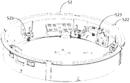
- Figure 5 is a schematic view of the second rotating member of Figure 2.
- FIG. 6 is a schematic diagram of a connection manner between a head mount and a cover according to another embodiment of the present invention.
- first and second are used for descriptive purposes only and are not to be construed as indicating or implying a relative importance or implicitly indicating the number of technical features indicated.
- features defining “first” or “second” may include one or more of the described features either explicitly or implicitly.
- the meaning of "a plurality" is two or more unless specifically and specifically defined otherwise.
- connection In the description of the present invention, it should be noted that the terms “installation”, “connected”, and “connected” are to be understood broadly, and may be fixed or detachable, for example, unless otherwise explicitly defined and defined. Connected, or integrally connected; may be mechanically connected, or may be electrically connected or may communicate with each other; may be directly connected or indirectly connected through an intermediate medium, may be internal communication of two elements or interaction of two elements relationship. For those skilled in the art, the specific meanings of the above terms in the present invention can be understood on a case-by-case basis.
- the display device 20 includes a display body 21 having a display side 21A for displaying an output image to the eyes of the user, and a boom 22 extending from the two ends of the display body 21 to the display side 21A direction A to form similar glasses. shape.
- the earphone device 30 includes two earphone bodies 31 for outputting audio signals.
- the head mount 40 includes a head portion 41 and a connecting portion 42 extending at each end of the head portion 41.
- the two sets of connecting mechanisms 50 are used to respectively connect the arms 22 at both ends of the display body 21 to the corresponding one of the earphone bodies 31 and the corresponding one of the connecting portions 42.
- the connecting mechanism 50 includes a first rotating member 51 that connects the corresponding one of the arms 22 and the corresponding earphone body 31, and further includes a second rotating member 52 rotatably engaged with the first rotating member 51.
- the second rotating member 52 is coupled to the corresponding one end connecting portion 42.
- the head-mounted display device includes a connection mechanism 50 for connecting the display device 20, the earphone device 30, and the head mount 40.
- the connection mechanism 50 includes: connecting one end of the display device 20 22 and a first rotating member 51 corresponding to a headphone body 31, and a first rotation
- the member 51 is rotatably coupled to the second rotating member 52.
- the second rotating member 52 is coupled to the one end connecting portion 42 of the head mount 40.
- the display device is driven by the relative rotation of the first rotating member 51 and the second rotating member 52.
- the 20 and the headrest 40 can be rotated relative to each other to provide a flexible connection, and the display device 20 and the headrest 40 can be stacked and stored, thereby improving the portability of the product.
- At least one of the two sets of connecting mechanisms 50 further includes an engaging structure 53 including: a circumferential wall 531 disposed on one of the first rotating member 51 and the second rotating member 52.
- the piece 52 is meshed with the elastic piece 533 by the tooth structure 532 under the action of an external force.
- the head mount 40 Under the engaging force formed by the toothed structure 532 and the elastic piece 533, the head mount 40 maintains a relative angle with the display device 20, and under the action of the external force, the elastic piece 533 is deformed to form a relative sliding with the toothed structure 532, so that the display device 20 is relatively rotated about an axis passing through the axis of the two earphone bodies 31.
- the engaging structure 53 may be disposed only in one set of connecting structures 50 or the engaging structures 53 may be disposed in the two sets of connecting mechanisms 50 to maintain the head mount 40 and the display device 20 relatively angle.
- the two types of connecting mechanisms 50 are provided with the engaging structure 53
- the pair may be caused.
- the other set of engaging structures 53 exerts a relatively small force, so that the rotation amounts of the two sets of engaging structures 53 are inconsistent, which is liable to cause equipment damage. Based on this problem, the above-mentioned problem is solved by providing the engaging structure 53 only in one set of the connecting structure 50, and the other connecting mechanism 50 is rotated by the engaging structure 53 in the set.
- the above embodiment of the present invention includes a connecting mechanism 50 for connecting the display device 20, the earphone device 30, and the head mount 40.
- the connecting mechanism 50 includes an engaging structure 53 having a toothed structure 532 and a resilient piece 533.
- the connecting mechanism 50 is rotated by the toothed structure 532 and the elastic piece 533 to rotate the display device 20 to rotate relative to the head mount 40, thereby providing a flexible connection manner, and the display device 20 and the head mount 40 can be stacked.
- Combined storage improves the portability of the product.
- the first rotating member 51 and the second rotating member 52 respectively include a locking member having the engaging structure 54
- the engaging structure 53 is provided on the engaging side faces 51A, 52A.
- the first rotating member 51 and the second rotating member 52 are annular frames including inner circumferential walls 51a, 52a and outer circumferential walls 51b, 52b, and the annular radius of the first rotating member 51 is larger or smaller than the first The annular radius of the two rotating members 52.
- the engaging structure 54 having one of the larger annular radii includes: the first engaging portion extending toward the center of the ring along the engaging side 51A or 52A
- the portion 541 and the second joint portion 542 extending from the first joint portion 541 in a direction away from the opposite side 51B or 52B.
- the second engaging portion 542 can be used to provide the circumferential wall 531 and the toothed structure 532 of the engaging structure 53 described above.
- the engaging structure 54 of one of the first rotating member 51 and the second rotating member 52 having a smaller annular radius includes a third engaging portion 543 extending away from the toroidal direction along the engaging side 52A or 51A.
- the first joint portion 541 is in contact with the third joint portion 543. Therefore, the third joint portion 543 having a smaller annular radius can be press-fitted to the first joint portion 543 through the inner portion of the larger annular radius, and the opposite side 51B or 52B of the annular frame body having the smaller annular radius can be The annular frame body having a larger annular radius protrudes, so that the first rotating member 51 and the second rotating member 52 achieve a rotatable snap-fit connection.
- the structure of the other set of connecting mechanisms 50 can be substantially the same as described above, except that the above-mentioned elastic piece 533 is not provided, or the above-mentioned elastic piece 533 and the toothed structure 532 are not provided.
- the annular radius of the first rotating member 51 is greater than the annular radius of the second rotating member 52.
- the invention is not limited to this.
- the second engaging portion 542 of the first rotating member 51 is a concentric ring extending from the annular frame, and the concentric ring includes an inner circumferential wall 542a and an outer circumferential wall 542b.
- the circumferential wall 531 and the toothed structure 532 of the engaging structure 53 are disposed on the second engaging portion 543.
- the toothed structure 532 is disposed on the inner circumferential wall 542a of the concentric ring.
- the inner circumferential wall 542a of the concentric ring can serve as the circumferential wall 531 of the engaging structure 53.
- the elastic piece 533 of the engaging structure 53 is fixed to the second rotating member 52. When the third engaging portion 543 of the second rotating member 52 is pressed against the first engaging portion 541 through the inside of the first rotating member 51, the elastic piece 533 and the toothed structure 532 Alignment engagement.
- the ring frame of the second rotating member 52 is provided with a spring fixing portion 521 disposed at a position corresponding to the tooth structure 532 after the second rotating member 52 is engaged with the first rotating member 51.
- the elastic piece fixing portion 521 is a limiting through hole corresponding to the shape of the elastic piece 533, and a portion of the elastic piece 533 is fixedly fixed to the inner side of the second rotating member 52, and a portion of the elastic piece 533 for engaging protrudes through the through hole.
- the alignment meshes the toothed structure 532.
- the present embodiment has two elastic piece fixing portions 521, and the elastic piece 533 has two exposed fixing portions 521 to engage with the toothed structure 532, and one of the portions is located in the gap between the adjacent two teeth of the toothed structure 532. At the other time, the other portion abuts the teeth of the toothed structure 532. In this way, the positioning accuracy of the rotation can be made to be half the pitch of the toothed structure 532.
- the first rotating member 51 and the second rotating member 52 are formed by an annular frame and are connected by a snapping structure 54 to form a receiving cavity through the annular frame, which can be used for accommodating electronic components.
- a snapping structure 54 to form a receiving cavity through the annular frame, which can be used for accommodating electronic components.
- PCB boards, batteries, etc. simplify the redundant structure of the head-mounted display device to additionally set the housing space.
- the outer cover of the buckle structure is disposed outside the accommodating space constructed by the annular frame body, which is convenient for disassembly, and is convenient for replacement, maintenance and repair of components.
- first rotating member 51 and the second rotating member 52 of the present invention are not limited to the annular frame, that is, the arrangement of the elastic piece 533 can be kept in mesh with the relative rotation of the toothed structure 532.
- one of the toothed structures 532 may adopt a frame having an outer square wall and an inner circumferential wall, and the toothed structure 532 is disposed on the inner circumferential wall;
- the other one may be an annular frame embedded in the above embodiment, or a circular entity embedded in a circular inner cavity constructed by the inner circumferential wall of the former one, and the elastic piece 533 is disposed on the circle of the circular entity.
- the outer wall engages the toothed structure 532 in position.
- one of the toothed structures 532 may also be an annular frame having a smaller annular radius, and the toothed structure 532 is disposed on the annular frame.
- the outer circumferential wall; one of the elastic pieces 533 may have an inner circumferential wall corresponding to the outer circumferential wall of the former one, and the outer shape is not limited, so that the toothed structure 532 may be embedded in the inner circumferential wall, and the elastic piece 533 passes through the outer circumferential wall.
- the inner circumferential wall is in intermeshing engagement with the inlaid former toothed structure 532.
- the opposite side 51B of the first rotating member 51 is connected to the earphone body 31 corresponding thereto.
- the connection between the earphone body 31 and the first rotating member 51 can be realized by the fixing member 80.
- the fixing member 80 is fixedly coupled to the opposite side 51B of the first rotating member 51, and the earphone body 31 is fixed to the fixing member 80.
- the specific fixing method may be a rivet fixing or any fixing method commonly used in the art.
- the head mounted display device 10 further includes a touch panel 60 disposed on the opposite side 52B of the second rotating member 52.
- the cover body 70 may be further included in the cover body 70.
- the cover body 70 includes a penetrating portion 71 and a fixing portion 72.
- the touch panel 60 is fixed to the cover body 70 and exposed to the outside through the penetrating portion 71.
- the fixing portion 72 is defined. It is fixedly coupled to the second rotating member 52.
- the second rotating member 52 includes a fixed connecting portion 525, specifically a rivet fixing hole, and is fixedly connected to the cover by rivets. Part 72.
- the connecting end 42 of the head mount 40 is pivotally coupled to the cover body 70 by a pivot.
- the cover body 70 includes a shaft hole 73 such that the pivot shaft 421 of the connection end 42 can pass through the shaft hole 73 and be fixed in the cover body 70.
- the connecting end 42 of the head mount 40 is pivotally coupled to the second rotating member 52 by a pivot.
- the second rotating member 52 includes a shaft hole 522, so that the pivot 421 of the connecting end 42 can pass through the shaft hole 522 from the outside of the second rotating member 52, and is fixed to the second rotation by the sleeve 523. Inside the piece 52.
- connection manner of the connecting end 42 of the headrest bracket 40 and the connecting mechanism 50 of the present invention is not limited to the above specific embodiment.
- the connecting end 42 of the head mount 40 may be integrally fixed to the second rotating member.
- the cover body 70 or the cover body 70 may be connected to the second rotating member 52 or the cover body 70 in a plugging manner, a snapping manner, or the like.
- the head mounted display device is rotatably connected by the engaging structure 54 of the first rotating member 51 and the second rotating member 52 of the connecting structure 50, wherein the head mount 40 is coupled to the second rotating member. 52.
- the boom 22 of the display device 20 is coupled to the first rotating member 51, so that the display device 20 and the head mount 40 can be rotated relative to each other under the rotation of the first rotating member 51 and the second rotating member 52.
- the connection includes a direct connection and an indirect connection through other parts.
- the engaging structure 53 functions to relatively rotate the first rotating member 51 and the second rotating member 52 in a damped manner, thereby achieving a relative angle between the positioning head portion 41 and the display body 21.
- the function is not limited to the present invention, and may be, for example, two rubber members as long as the first and second rotating members 51 and 52 are relatively damped relative to each other. Damping structure can be.
Abstract
A head mounted display apparatus, comprising: a display device (20), comprising a display body (21) and two booms (22) extending from the opposite ends of the display body (21); an earphone device (30), comprising two earphone bodies (31) for outputting an audio signal; a head mounted bracket (40), comprising two connection parts (42) extending from both ends of the head mounted bracket (40) respectively; and two groups of connecting mechanisms (50) for connecting each boom (22) to corresponding earphone body (21) and connection part (42); each connecting mechanism comprising a first rotating member (51) for connecting the boom (22) to a corresponding earphone body (21), and a second rotating member (52) rotatably jointed with the first rotating member (51), the second rotating member (52) being connected to a connection part (42) of the corresponding end. The present head mounted display apparatus is driven by means of the relative rotation of the first rotating member and the second rotating member, the display device and the head mounted bracket being rotatable relative to each other, thereby enabling the display device and the head mounted bracket to be folded and accommodated, improving the portability of the product.
Description
本发明涉及一种穿戴式显示设备。The present invention relates to a wearable display device.
头戴式显示设备(HMD,Head Mount Display),采用近眼显示技术,通过一组光学系统(主要是精密光学透镜)放大超微显示屏上的图像,将影像投射于视网膜上,进而呈现于观看者眼中大屏幕图像。由于头戴式显示设备的外形基本类似于眼镜,因此也被形象的称呼为视频眼镜(video glasses),提出了一种便携式家庭影院的产品概念。Head mounted display (HMD), using near-eye display technology, amplifies the image on the ultra-micro display through a set of optical systems (mainly precision optical lenses), projects the image onto the retina, and then presents it for viewing. Large screen image in the eyes of the person. Since the shape of the head-mounted display device is basically similar to that of glasses, it is also referred to as video glasses, and a product concept of a portable home theater is proposed.
现有产品中,大部分通过有线连接入耳式耳机的方式来提高头戴式显示设备的便携性,进而将“家庭影院”的随身、便携概念产品化。但是,入耳式耳机音效较为普通,因此,现有产品也有直接嵌入头戴式耳机的,但这种结合一体的方式致使产品体积较大,便携性有限。因此,如何提高头戴式显示设备的整体特性的同时保证其便携性,是产品普及过程中急需解决的问题。Most of the existing products improve the portability of the head-mounted display device by wiredly connecting the in-ear headphones, thereby further realizing the portable and portable concept of the "home theater". However, the in-ear headphones have a relatively common sound effect. Therefore, the existing products are also directly embedded in the headphones, but the integrated method results in a large product volume and limited portability. Therefore, how to improve the overall characteristics of the head-mounted display device while ensuring its portability is an urgent problem to be solved in the process of product popularization.
发明内容Summary of the invention
本发明的目的在于提供一种可解决上述技术问题的头戴式显示设备,包括:It is an object of the present invention to provide a head mounted display device that can solve the above technical problems, including:
显示装置,包括一显示体及两个字该显示体相对两端分别延伸的臂架;The display device comprises a display body and two arms extending respectively at opposite ends of the display body;
耳机装置,包括用于输出音频信号的两个耳机体;a headphone device comprising two earphone bodies for outputting an audio signal;
头戴支架,包括头戴部及两个自该头戴部两端分别延伸的连接部;及a head mount comprising a headband and two connecting portions extending from opposite ends of the headwear; and
两组连接机构,用于分别将各臂架连接至对应的一个耳机体及连接部;各连接机构包括连接该臂架及其对应耳机体的第一旋转件,及与第一旋转件可转
动接合的第二旋转件,该第二旋转件连接至该对应的一端连接部。Two sets of connecting mechanisms for respectively connecting the booms to a corresponding one of the earphone body and the connecting portion; each connecting mechanism comprises a first rotating member connecting the arm frame and its corresponding earphone body, and is rotatable with the first rotating member
A second rotating member that is movably coupled, the second rotating member being coupled to the corresponding one end connection.
本发明实施例提供的一种头戴式显示设备,包括了用于连接显示装置、耳机装置及头戴支架的连接机构,该连接机构包括:连接显示装置一端臂架及对应一耳机体的第一旋转件,以及与第一旋转件可转动接合的第二旋转件,该第二旋转件连接至头戴支架的一端连接部,在第一旋转件及第二旋转件相对转动的带动下,显示装置与头戴支架可实现相对转动,提供了一种灵活的连接方式,进而可将显示装置及头戴支架叠合收纳,提高了产品的便携性。A head-mounted display device according to an embodiment of the present invention includes a connection mechanism for connecting a display device, an earphone device, and a head mount, the connection mechanism including: an end arm of the display device and a corresponding one of the earphone bodies a rotating member, and a second rotating member rotatably coupled to the first rotating member, the second rotating member is coupled to the one end connecting portion of the head mount, and driven by the relative rotation of the first rotating member and the second rotating member, The display device and the head mount can realize relative rotation, and provide a flexible connection method, thereby stacking and arranging the display device and the head mount, thereby improving the portability of the product.
图1是本发明一实施例提供的一种头戴式显示设备示意图。FIG. 1 is a schematic diagram of a head mounted display device according to an embodiment of the invention.
图2是本发明实施例提供的一种头戴式显示设备的连接机构分解示意图。FIG. 2 is an exploded perspective view of a connection mechanism of a head mounted display device according to an embodiment of the present invention.
图3是图2中第一旋转件与第二旋转件的装配示意图。Figure 3 is a schematic view showing the assembly of the first rotating member and the second rotating member of Figure 2;
图4是图3装配后的啮合结构局部放大示意图。Figure 4 is a partially enlarged schematic view of the engaged structure of Figure 3 after assembly.
图5为图2中第二旋转件的示意图。Figure 5 is a schematic view of the second rotating member of Figure 2.
图6为本发明又一实施例提供的一种头戴支架与盖体的连接方式示意图。FIG. 6 is a schematic diagram of a connection manner between a head mount and a cover according to another embodiment of the present invention.
为了使本发明的目的、技术方案及优点更加清楚明白,以下结合附图及实施例,对本发明进行进一步详细说明。应当理解,此处所描述的具体实施例仅仅用以解释本发明,并不用于限定本发明。The present invention will be further described in detail below with reference to the accompanying drawings and embodiments. It is understood that the specific embodiments described herein are merely illustrative of the invention and are not intended to limit the invention.
在本发明的描述中,需要理解的是,术语“第一”、“第二”仅用于描述目的,而不能理解为指示或暗示相对重要性或者隐含指明所指示的技术特征的数量。由此,限定有“第一”、“第二”的特征可以明示或者隐含地包括一个或者更多个所述特征。在本发明的描述中,“多个”的含义是两个或两个以上,除非另有明确具体的限定。
In the description of the present invention, it is to be understood that the terms "first" and "second" are used for descriptive purposes only and are not to be construed as indicating or implying a relative importance or implicitly indicating the number of technical features indicated. Thus, features defining "first" or "second" may include one or more of the described features either explicitly or implicitly. In the description of the present invention, the meaning of "a plurality" is two or more unless specifically and specifically defined otherwise.
在本发明的描述中,需要说明的是,除非另有明确的规定和限定,术语“安装”、“相连”、“连接”应做广义理解,例如,可以是固定连接,也可以是可拆卸连接,或一体地连接;可以是机械连接,也可以是电连接或可以相互通信;可以是直接相连,也可以通过中间媒介间接相连,可以是两个元件内部的连通或两个元件的相互作用关系。对于本领域的普通技术人员而言,可以根据具体情况理解上述术语在本发明中的具体含义。In the description of the present invention, it should be noted that the terms "installation", "connected", and "connected" are to be understood broadly, and may be fixed or detachable, for example, unless otherwise explicitly defined and defined. Connected, or integrally connected; may be mechanically connected, or may be electrically connected or may communicate with each other; may be directly connected or indirectly connected through an intermediate medium, may be internal communication of two elements or interaction of two elements relationship. For those skilled in the art, the specific meanings of the above terms in the present invention can be understood on a case-by-case basis.
下文的公开提供了许多不同的实施方式或例子用来实现本发明的不同结构。为了简化本发明的公开,下文中对特定例子的部件和设定进行描述。当然,它们仅仅为示例,并且目的不在于限制本发明。此外,本发明可以在不同例子中重复参考数字和/或参考字母,这种重复是为了简化和清楚的目的,其本身不指示所讨论各种实施方式和/或设定之间的关系。此外,本发明提供了的各种特定的工艺和材料的例子,但是本领域普通技术人员可以意识到其他工艺的应用和/或其他材料的使用。The following disclosure provides many different embodiments or examples for implementing different structures of the present invention. In order to simplify the disclosure of the present invention, the components and settings of specific examples are described below. Of course, they are merely examples and are not intended to limit the invention. In addition, the present invention may be repeated with reference to the numerals and/or reference numerals in the various examples, which are for the purpose of simplification and clarity, and do not indicate the relationship between the various embodiments and/or settings discussed. Moreover, the present invention provides examples of various specific processes and materials, but one of ordinary skill in the art will recognize the use of other processes and/or the use of other materials.
请参照图1,为本发明实施例提供的一种头戴式显示设备,包括显示装置20、耳机装置30、头戴支架40及连接机构50。其中,显示装置20包括具有显示侧21A的显示体21,该显示侧21A用于显示输出图像至用户双眼;及显示体21两端分别向显示侧21A方向A延伸的臂架22,形成类似眼镜的形状。耳机装置30包括用于输出音频信号的两个耳机体31。头戴支架40包括头戴部41,及该头戴部41两端分别延伸的连接部42。两组连接机构50用于分别连接显示体21两端的臂架22至对应的一个耳机体31及对应的一个连接部42。结合图2至图4,该连接机构50包括连接对应的一个臂架22及与其对应耳机体31的第一旋转件51,还包括与第一旋转件51可转动接合的第二旋转件52,该第二旋转件52连接至对应的一端连接部42。1 is a head-mounted display device according to an embodiment of the present invention, including a display device 20, an earphone device 30, a head mount 40, and a connection mechanism 50. The display device 20 includes a display body 21 having a display side 21A for displaying an output image to the eyes of the user, and a boom 22 extending from the two ends of the display body 21 to the display side 21A direction A to form similar glasses. shape. The earphone device 30 includes two earphone bodies 31 for outputting audio signals. The head mount 40 includes a head portion 41 and a connecting portion 42 extending at each end of the head portion 41. The two sets of connecting mechanisms 50 are used to respectively connect the arms 22 at both ends of the display body 21 to the corresponding one of the earphone bodies 31 and the corresponding one of the connecting portions 42. 2 to 4, the connecting mechanism 50 includes a first rotating member 51 that connects the corresponding one of the arms 22 and the corresponding earphone body 31, and further includes a second rotating member 52 rotatably engaged with the first rotating member 51. The second rotating member 52 is coupled to the corresponding one end connecting portion 42.
本发明上述实施例提供的一种头戴式显示设备,包括了用于连接显示装置20、耳机装置30及头戴支架40的连接机构50,该连接机构50包括:连接显示装置20一端臂架22及对应一耳机体31的第一旋转件51,以及与第一旋转
件51可转动接合的第二旋转件52,该第二旋转件52连接至头戴支架40的一端连接部42,在第一旋转件51及第二旋转件52相对转动的带动下,显示装置20与头戴支架40可实现相对转动,提供了一种灵活的连接方式,进而可将显示装置20及头戴支架40叠合收纳,提高了产品的便携性。The head-mounted display device provided by the above embodiment of the present invention includes a connection mechanism 50 for connecting the display device 20, the earphone device 30, and the head mount 40. The connection mechanism 50 includes: connecting one end of the display device 20 22 and a first rotating member 51 corresponding to a headphone body 31, and a first rotation
The member 51 is rotatably coupled to the second rotating member 52. The second rotating member 52 is coupled to the one end connecting portion 42 of the head mount 40. The display device is driven by the relative rotation of the first rotating member 51 and the second rotating member 52. The 20 and the headrest 40 can be rotated relative to each other to provide a flexible connection, and the display device 20 and the headrest 40 can be stacked and stored, thereby improving the portability of the product.
该实施例中,两组连接机构50中至少有一组连接机构50还包括啮合结构53,该啮合结构53包括:设置在第一旋转件51及第二旋转件52二者之一的圆周壁531之上的齿形结构532,以及固定至第一旋转件51及第二旋转件52之另一者之上的与齿形结构532啮合的弹片533,该第一旋转件51与该第二旋转件52在外力作用下通过齿形结构532与弹片533啮合转动。在齿形结构532与弹片533形成的啮合作用力下头戴支架40与显示装置20维持相对角度,在外力的作用下,使得弹片533发生形变,与齿形结构532形成相对滑动,使得显示装置20绕着贯穿两个耳机体31的轴心的轴线发生相对旋转。需说明的是,两组连接机构50中,可仅于一组连接结构50中设置啮合结构53或者两组连接机构50中均设置啮合结构53,以实现头戴支架40与显示装置20维持相对角度。In this embodiment, at least one of the two sets of connecting mechanisms 50 further includes an engaging structure 53 including: a circumferential wall 531 disposed on one of the first rotating member 51 and the second rotating member 52. The upper toothed structure 532, and the elastic piece 533 fixed to the tooth structure 532 fixed to the other of the first rotating member 51 and the second rotating member 52, the first rotating member 51 and the second rotation The piece 52 is meshed with the elastic piece 533 by the tooth structure 532 under the action of an external force. Under the engaging force formed by the toothed structure 532 and the elastic piece 533, the head mount 40 maintains a relative angle with the display device 20, and under the action of the external force, the elastic piece 533 is deformed to form a relative sliding with the toothed structure 532, so that the display device 20 is relatively rotated about an axis passing through the axis of the two earphone bodies 31. It should be noted that, in the two sets of connecting mechanisms 50, the engaging structure 53 may be disposed only in one set of connecting structures 50 or the engaging structures 53 may be disposed in the two sets of connecting mechanisms 50 to maintain the head mount 40 and the display device 20 relatively angle.
某些情形下,当两组连接机构50中均设置有啮合结构53时,若用户施力不当,如对显示装置20及头戴支架40偏向一组连接机构50的位置拉动时,会造成对另一组啮合结构53施力相对较小,从而两组啮合结构53转动量不一致,易造成设备损坏。基于此问题,采用仅在一组连接结构50中设置啮合结构53,由该组中的啮合结构53带动另一组连接机构50同步转动,从而解决上述问题。In some cases, when the two types of connecting mechanisms 50 are provided with the engaging structure 53, if the user applies improper force, such as when the display device 20 and the head mount 40 are biased toward the position of the set of connecting mechanisms 50, the pair may be caused. The other set of engaging structures 53 exerts a relatively small force, so that the rotation amounts of the two sets of engaging structures 53 are inconsistent, which is liable to cause equipment damage. Based on this problem, the above-mentioned problem is solved by providing the engaging structure 53 only in one set of the connecting structure 50, and the other connecting mechanism 50 is rotated by the engaging structure 53 in the set.
本发明的上述实施例,包括了用于连接显示装置20、耳机装置30及头戴支架40的连接机构50,该连接机构50包括:具有齿形结构532及弹片533的啮合结构53,在外力作用下连接机构50通过齿形结构532与弹片533啮合旋转,带动显示装置20与头戴支架40发生相对旋转,提供了一种灵活的连接方式,进而可将显示装置20及头戴支架40叠合收纳,提高了产品的便携性。The above embodiment of the present invention includes a connecting mechanism 50 for connecting the display device 20, the earphone device 30, and the head mount 40. The connecting mechanism 50 includes an engaging structure 53 having a toothed structure 532 and a resilient piece 533. The connecting mechanism 50 is rotated by the toothed structure 532 and the elastic piece 533 to rotate the display device 20 to rotate relative to the head mount 40, thereby providing a flexible connection manner, and the display device 20 and the head mount 40 can be stacked. Combined storage improves the portability of the product.
具体的,第一旋转件51及第二旋转件52分别包括具有卡合结构54的卡合
边侧51A、52A,及与卡合边侧51A、52A相对的对侧51B、52B。啮合结构53设置于卡合边侧51A、52A。较优的实施方式中,第一旋转件51及第二旋转件52为包括内圆周壁51a、52a及外圆周壁51b、52b的环形框体,第一旋转件51的环形半径大于或小于第二旋转件52的环形半径。进一步的,第一旋转件51及第二旋转件52二者中,具有较大环形半径的一者的卡合结构54包括:沿卡合边侧51A或52A朝向环心方向延伸的第一接合部541,以及由该第一接合部541朝向背离对侧51B或52B的方向延伸的第二接合部542。具体的,第二接合部542可以用以设置上述啮合结构53的圆周壁531及齿形结构532。第一旋转件51及第二旋转件52二者中具有较小环形半径的一者的卡合结构54包括:沿卡合边侧52A或51A朝向背离环心方向延伸的第三接合部543。该第一接合部541与该第三接合部543贴合。从而环形半径较小一者的第三结合部543可通过环形半径较大一者的内部压合于第一接合部543,且环形半径较小一者的环形框体的对侧51B或52B可通过环形半径较大一者的环形框体伸出,从而第一旋转件51与第二旋转件52实现可转动的卡合连接。另一组连接机构50的结构可与上述描述基本相同,不同之处仅在于不具有上述弹片533,或者不具有上述弹片533及齿形结构532。Specifically, the first rotating member 51 and the second rotating member 52 respectively include a locking member having the engaging structure 54
The side faces 51A and 52A and the opposite sides 51B and 52B opposed to the engaging side faces 51A and 52A. The engaging structure 53 is provided on the engaging side faces 51A, 52A. In a preferred embodiment, the first rotating member 51 and the second rotating member 52 are annular frames including inner circumferential walls 51a, 52a and outer circumferential walls 51b, 52b, and the annular radius of the first rotating member 51 is larger or smaller than the first The annular radius of the two rotating members 52. Further, in both the first rotating member 51 and the second rotating member 52, the engaging structure 54 having one of the larger annular radii includes: the first engaging portion extending toward the center of the ring along the engaging side 51A or 52A The portion 541 and the second joint portion 542 extending from the first joint portion 541 in a direction away from the opposite side 51B or 52B. Specifically, the second engaging portion 542 can be used to provide the circumferential wall 531 and the toothed structure 532 of the engaging structure 53 described above. The engaging structure 54 of one of the first rotating member 51 and the second rotating member 52 having a smaller annular radius includes a third engaging portion 543 extending away from the toroidal direction along the engaging side 52A or 51A. The first joint portion 541 is in contact with the third joint portion 543. Therefore, the third joint portion 543 having a smaller annular radius can be press-fitted to the first joint portion 543 through the inner portion of the larger annular radius, and the opposite side 51B or 52B of the annular frame body having the smaller annular radius can be The annular frame body having a larger annular radius protrudes, so that the first rotating member 51 and the second rotating member 52 achieve a rotatable snap-fit connection. The structure of the other set of connecting mechanisms 50 can be substantially the same as described above, except that the above-mentioned elastic piece 533 is not provided, or the above-mentioned elastic piece 533 and the toothed structure 532 are not provided.
为了详细阐述上述原理,以下结合一具体实施例加以阐述。该实施例中,第一旋转件51的环形半径大于第二旋转件52的环形半径。但本发明并不限于此。In order to explain the above principles in detail, the following is explained in conjunction with a specific embodiment. In this embodiment, the annular radius of the first rotating member 51 is greater than the annular radius of the second rotating member 52. However, the invention is not limited to this.
第一旋转件51的第二接合部542为环形框体延伸的同心环,该同心环包括内圆周壁542a及外圆周壁542b。该实施例中,啮合结构53的圆周壁531及齿形结构532设置于该第二接合部543,具体的,齿形结构532设于该同心环的内圆周壁542a,可以理解的是,该同心环的内圆周壁542a可以作为啮合结构53的圆周壁531。啮合结构53的弹片533固定于第二旋转件52,当第二旋转件52的第三接合部543通过第一旋转件51的内部压合于第一接合部541,弹片533与齿形结构532对位啮合。
The second engaging portion 542 of the first rotating member 51 is a concentric ring extending from the annular frame, and the concentric ring includes an inner circumferential wall 542a and an outer circumferential wall 542b. In this embodiment, the circumferential wall 531 and the toothed structure 532 of the engaging structure 53 are disposed on the second engaging portion 543. Specifically, the toothed structure 532 is disposed on the inner circumferential wall 542a of the concentric ring. It can be understood that the The inner circumferential wall 542a of the concentric ring can serve as the circumferential wall 531 of the engaging structure 53. The elastic piece 533 of the engaging structure 53 is fixed to the second rotating member 52. When the third engaging portion 543 of the second rotating member 52 is pressed against the first engaging portion 541 through the inside of the first rotating member 51, the elastic piece 533 and the toothed structure 532 Alignment engagement.
具体的,该实施方式中,第二旋转件52的环形框体上设有弹片固定部521,设置于第二旋转件52与第一旋转件51卡合连接后对应齿形结构532的位置。具体的,该例中,弹片固定部521为对应弹片533形状的限位通孔,弹片533的部分限位固定于第二旋转件52的内侧,弹片533用于啮合的部分通过通孔伸出,对位啮合齿形结构532。优选地,本实施方式具有两个弹片固定部521,弹片533具有两个露出固定部521以与齿形结构532啮合的部分,并且其中一个部分位于齿形结构532相邻两个齿的空隙中时,另一个部分抵持齿形结构532的齿。如此,能使转动的定位精度达到齿形结构532的齿距的一半。Specifically, in this embodiment, the ring frame of the second rotating member 52 is provided with a spring fixing portion 521 disposed at a position corresponding to the tooth structure 532 after the second rotating member 52 is engaged with the first rotating member 51. Specifically, in this example, the elastic piece fixing portion 521 is a limiting through hole corresponding to the shape of the elastic piece 533, and a portion of the elastic piece 533 is fixedly fixed to the inner side of the second rotating member 52, and a portion of the elastic piece 533 for engaging protrudes through the through hole. The alignment meshes the toothed structure 532. Preferably, the present embodiment has two elastic piece fixing portions 521, and the elastic piece 533 has two exposed fixing portions 521 to engage with the toothed structure 532, and one of the portions is located in the gap between the adjacent two teeth of the toothed structure 532. At the other time, the other portion abuts the teeth of the toothed structure 532. In this way, the positioning accuracy of the rotation can be made to be half the pitch of the toothed structure 532.
本发明较优实施方式中,第一旋转件51、第二旋转件52采用环形框体,并采用卡合结构54连接,从而通过环形框体构建了容置内腔,可用以容置电子元件,如PCB板、电池等,精简了头戴式显示设备需额外设置容置空间的冗余结构。较优的,还可在环形框体构建的容置空间外侧设置卡扣结构的外盖,方便拆卸,便于对元件的更换、维护、修理等。In a preferred embodiment of the present invention, the first rotating member 51 and the second rotating member 52 are formed by an annular frame and are connected by a snapping structure 54 to form a receiving cavity through the annular frame, which can be used for accommodating electronic components. For example, PCB boards, batteries, etc., simplify the redundant structure of the head-mounted display device to additionally set the housing space. Preferably, the outer cover of the buckle structure is disposed outside the accommodating space constructed by the annular frame body, which is convenient for disassembly, and is convenient for replacement, maintenance and repair of components.
但本发明的第一旋转件51、第二旋转件52并不限于环形框体,即弹片533的设置可沿齿形结构532相对旋转而保持啮合即可。如,第一旋转件51或第二旋转件52二者中,具有齿形结构532的一者可以采用外方形壁、内圆周壁的框体,齿形结构532设于内圆周壁;相应的,另一者可以为上述实施例中内嵌的环形框体,也可以为内嵌于前一者内圆周壁构建的圆形内腔的圆形实体,弹片533设于该圆形实体的圆形外壁与齿形结构532对位啮合。可以理解的是,第一旋转件51及第二旋转件52二者中,具有齿形结构532的一者也可以为环形半径较小的环形框体,齿形结构532设置于该环形框体的外圆周壁;具有弹片533的一者可以为具有与前一者外圆周壁对应的内圆周壁、而外形不限,从而齿形结构532可以内嵌于该内圆周壁,弹片533通过该内圆周壁与内嵌的前一者齿形结构532对位啮合。本领域技术人员根据该原理构建的第一旋转件、第二旋转件的相对啮合旋转方式均属于本发明范围内。However, the first rotating member 51 and the second rotating member 52 of the present invention are not limited to the annular frame, that is, the arrangement of the elastic piece 533 can be kept in mesh with the relative rotation of the toothed structure 532. For example, in the first rotating member 51 or the second rotating member 52, one of the toothed structures 532 may adopt a frame having an outer square wall and an inner circumferential wall, and the toothed structure 532 is disposed on the inner circumferential wall; The other one may be an annular frame embedded in the above embodiment, or a circular entity embedded in a circular inner cavity constructed by the inner circumferential wall of the former one, and the elastic piece 533 is disposed on the circle of the circular entity. The outer wall engages the toothed structure 532 in position. It can be understood that, in both the first rotating member 51 and the second rotating member 52, one of the toothed structures 532 may also be an annular frame having a smaller annular radius, and the toothed structure 532 is disposed on the annular frame. The outer circumferential wall; one of the elastic pieces 533 may have an inner circumferential wall corresponding to the outer circumferential wall of the former one, and the outer shape is not limited, so that the toothed structure 532 may be embedded in the inner circumferential wall, and the elastic piece 533 passes through the outer circumferential wall. The inner circumferential wall is in intermeshing engagement with the inlaid former toothed structure 532. The relative meshing and rotating manner of the first rotating member and the second rotating member constructed by those skilled in the art according to the principle are all within the scope of the present invention.
该实施方式下,第一旋转件51的对侧51B连接与其对应的耳机体31。具
体的,可以通过固定件80实现耳机体31与第一旋转件51的连接。将固定件80固定连接于第一旋转件51的对侧51B,耳机体31固定于该固定件80。具体固定方式可以为铆钉固定,也可以为本领域常用的任何固定方式。In this embodiment, the opposite side 51B of the first rotating member 51 is connected to the earphone body 31 corresponding thereto. With
The connection between the earphone body 31 and the first rotating member 51 can be realized by the fixing member 80. The fixing member 80 is fixedly coupled to the opposite side 51B of the first rotating member 51, and the earphone body 31 is fixed to the fixing member 80. The specific fixing method may be a rivet fixing or any fixing method commonly used in the art.
较优的,该头戴式显示设备10还包括触控板60,触控板60设置于第二旋转件52的对侧52B。具体的,可结合参考图6,还可以包括盖体70,盖体70包括穿透部71及固定部72,触控板60固定于盖体70并通过穿透部71对外显露;固定部72与第二旋转件52固定连接。具体的,作为头戴支架40与连接机构50的又一实施方式,如图5所示,第二旋转件52包括固定连接部525,具体为铆钉固定孔,通过铆钉固定连接至盖体的固定部72。该方式下,头戴支架40的连接端42通过枢轴可转动的连接于盖体70。盖体70包括轴孔73,从而连接端42的枢轴421可穿过轴孔73,固定于盖体70内。Preferably, the head mounted display device 10 further includes a touch panel 60 disposed on the opposite side 52B of the second rotating member 52. Specifically, the cover body 70 may be further included in the cover body 70. The cover body 70 includes a penetrating portion 71 and a fixing portion 72. The touch panel 60 is fixed to the cover body 70 and exposed to the outside through the penetrating portion 71. The fixing portion 72 is defined. It is fixedly coupled to the second rotating member 52. Specifically, as another embodiment of the head mount 40 and the connecting mechanism 50, as shown in FIG. 5, the second rotating member 52 includes a fixed connecting portion 525, specifically a rivet fixing hole, and is fixedly connected to the cover by rivets. Part 72. In this manner, the connecting end 42 of the head mount 40 is pivotally coupled to the cover body 70 by a pivot. The cover body 70 includes a shaft hole 73 such that the pivot shaft 421 of the connection end 42 can pass through the shaft hole 73 and be fixed in the cover body 70.
其他实施方式中,当不具有盖体70时,头戴支架40的连接端42通过枢轴可转动的连接于第二旋转件52。具体的,如图6所示,第二旋转件52包括轴孔522,从而连接端42的枢轴421可由第二旋转件52的外侧穿过轴孔522,通过轴套523固定于第二旋转件52内侧。In other embodiments, when the cover 70 is not provided, the connecting end 42 of the head mount 40 is pivotally coupled to the second rotating member 52 by a pivot. Specifically, as shown in FIG. 6, the second rotating member 52 includes a shaft hole 522, so that the pivot 421 of the connecting end 42 can pass through the shaft hole 522 from the outside of the second rotating member 52, and is fixed to the second rotation by the sleeve 523. Inside the piece 52.
但本发明头戴支架40的连接端42与连接机构50的连接方式并不限于上述具体实施方式,如图1所示,头戴支架40的连接端42可以为一体固定成型于第二旋转件52或盖体70,也可以为插接方式、卡扣方式等连接至第二旋转件52或盖体70。However, the connection manner of the connecting end 42 of the headrest bracket 40 and the connecting mechanism 50 of the present invention is not limited to the above specific embodiment. As shown in FIG. 1, the connecting end 42 of the head mount 40 may be integrally fixed to the second rotating member. The cover body 70 or the cover body 70 may be connected to the second rotating member 52 or the cover body 70 in a plugging manner, a snapping manner, or the like.
上述较优实施方式中,该头戴式显示设备通过连接结构50第一旋转件51与第二旋转件52的卡合结构54实现可转动连接,其中,头戴支架40连接于第二旋转件52,显示装置20的臂架22连接于第一旋转件51,从而显示装置20与头戴支架40可以在第一旋转件51及第二旋转件52的转动下实现相对转动。其中,所述的连接包括直接连接也包括通过其他件间接连接。In the above preferred embodiment, the head mounted display device is rotatably connected by the engaging structure 54 of the first rotating member 51 and the second rotating member 52 of the connecting structure 50, wherein the head mount 40 is coupled to the second rotating member. 52. The boom 22 of the display device 20 is coupled to the first rotating member 51, so that the display device 20 and the head mount 40 can be rotated relative to each other under the rotation of the first rotating member 51 and the second rotating member 52. Wherein, the connection includes a direct connection and an indirect connection through other parts.
上述实施方式中,啮合结构53起到了使第一转件51及第二旋转件52以有阻尼的方式相对转动的作用,进而起到定位头戴部41与显示体21的相对夹角
的功能。然而可以理解,能起到上述功能的不限于本发明的啮合结构53,比如可以是两个橡胶件,只要是起到能使该第一及第二旋转件51及52有阻尼地相对转动的阻尼结构便可。In the above embodiment, the engaging structure 53 functions to relatively rotate the first rotating member 51 and the second rotating member 52 in a damped manner, thereby achieving a relative angle between the positioning head portion 41 and the display body 21.
The function. However, it can be understood that the engaging structure 53 capable of performing the above functions is not limited to the present invention, and may be, for example, two rubber members as long as the first and second rotating members 51 and 52 are relatively damped relative to each other. Damping structure can be.
以上所述仅为本发明的较佳实施例而已,并不用以限制本发明,凡在本发明的精神和原则之内所作的任何修改、等同替换和改进等,均应包含在本发明的保护范围之内。
The above is only the preferred embodiment of the present invention, and is not intended to limit the present invention. Any modifications, equivalent substitutions and improvements made within the spirit and principles of the present invention should be included in the protection of the present invention. Within the scope.
Claims (14)
- 一种头戴式显示设备,其特征在于,包括:A head mounted display device, comprising:显示装置,包括一显示体及两个自该显示体相对两端分别延伸的臂架;The display device includes a display body and two booms respectively extending from opposite ends of the display body;耳机装置,包括用于输出音频信号的两个耳机体;a headphone device comprising two earphone bodies for outputting an audio signal;头戴支架,包括头戴部及两个自该头戴部两端分别延伸的连接部;及a head mount comprising a headband and two connecting portions extending from opposite ends of the headwear; and两组连接机构,用于分别将各臂架连接至对应的一个耳机体及连接部;各连接机构包括连接该臂架及其对应耳机体的第一旋转件,及与第一旋转件可转动接合的第二旋转件,该第二旋转件连接至对应的一端连接部。Two sets of connecting mechanisms for respectively connecting the booms to a corresponding one of the earphone body and the connecting portion; each connecting mechanism comprises a first rotating member connecting the arm frame and its corresponding earphone body, and is rotatable with the first rotating member A second rotating member that is coupled to the corresponding one end connection.
- 如权利要求1所述的头戴式显示设备,其特征在于,所述两组连接机构中至少有一组连接机构还包括:使所述第一旋转件及第二旋转件有阻尼地相对转动的阻尼结构。The head-mounted display device according to claim 1, wherein at least one of the two sets of connecting mechanisms further comprises: dampingly rotating the first rotating member and the second rotating member Damping structure.
- 如权利要求2所述的头戴式显示设备,其特征在于,所述阻尼结构为啮合结构,其包括:所述第一旋转件及第二旋转件二者之一包括设有齿形结构的圆周壁,另一者包括设有与所述齿形结构啮合的弹片,该第一旋转件与该第二旋转件在外力作用下通过齿形结构与弹片啮合转动。The head-mounted display device according to claim 2, wherein the damping structure is an engaging structure, comprising: one of the first rotating member and the second rotating member comprising a toothed structure The circumferential wall, the other includes a resilient piece that is engaged with the toothed structure, and the first rotating member and the second rotating member are meshed with the elastic piece by a toothed structure under an external force.
- 如权利要求3所述的头戴式显示设备,其特征在于,所述第一旋转件及第二旋转件分别包括具有卡合结构的卡合边侧及与该卡合边侧相对的对侧;所述啮合结构设置于所述卡合边侧。The head-mounted display device according to claim 3, wherein the first rotating member and the second rotating member respectively include a engaging side having an engaging structure and a opposite side opposite to the engaging side The engaging structure is disposed on the side of the engaging side.
- 如权利要求4所述的头戴式显示设备,其特征在于,所述第一旋转件及第二旋转件为包括内圆周壁及外圆周壁的环形框体,所述第一旋转件的环形半径大于或小于所述第二旋转件的环形半径。The head-mounted display device according to claim 4, wherein the first rotating member and the second rotating member are annular frames including an inner circumferential wall and an outer circumferential wall, and the first rotating member has a ring shape. The radius is greater or smaller than the annular radius of the second rotating member.
- 如权利要求5所述的头戴式显示设备,其特征在于,第一旋转件及第二旋转件二者中具有较大环形半径的一者的卡合结构包括:沿卡合边侧朝向环心 方向延伸的第一接合部,以及由该第一接合部朝向背离所述对侧的方向延伸的第二接合部;所述第一旋转件及第二旋转件二者中具有较小环形半径的一者的卡合结构包括:沿卡合边侧朝向背离环心方向延伸的第三接合部;该第一接合部与该第三接合部贴合。The head-mounted display device according to claim 5, wherein the engaging structure of one of the first rotating member and the second rotating member having a larger annular radius comprises: facing the ring along the engaging side Heart a first extending portion extending in a direction, and a second engaging portion extending from the first engaging portion toward a direction away from the opposite side; the first rotating member and the second rotating member having a smaller annular radius The engaging structure of one includes a third engaging portion extending away from the center of the ring along the engaging side; the first engaging portion is in contact with the third engaging portion.
- 如权利要求6所述的头戴式显示设备,其特征在于,所述第一旋转件的环形半径大于所述第二旋转件的环形半径。A head-mounted display device according to claim 6, wherein the annular radius of the first rotating member is larger than the annular radius of the second rotating member.
- 如权利要求7所述的头戴式显示设备,其特征在于,所述第一旋转件的第二接合部为所述环形框体延伸的同心环,该同心环包括内圆周壁及外圆周壁;The head-mounted display device according to claim 7, wherein the second engaging portion of the first rotating member is a concentric ring extending from the annular frame, and the concentric ring includes an inner circumferential wall and an outer circumferential wall ;所述齿形结构设于该同心环的内圆周壁;The toothed structure is disposed on an inner circumferential wall of the concentric ring;所述弹片固定于所述第二旋转件,当所述第二旋转件的第三接合部通过所述第一旋转件的内部压合于所述第一接合部,所述弹片与所述齿形结构对位啮合。The elastic piece is fixed to the second rotating member, and when the third engaging portion of the second rotating member is pressed against the first engaging portion by the inside of the first rotating member, the elastic piece and the tooth The shape structure is engaged in position.
- 如权利要求3所述的头戴式显示设备,其特征在于,具有所述弹片的所述第一旋转件或所述第二旋转件还包括:两个弹片固定部,所述弹片具有两个露出该弹片固定部以与所述齿形结构啮合的部分,并且其中一个部分位于齿形结构相邻两个齿的空隙中时,另一个部分抵持齿形结构的齿。A head-mounted display device according to claim 3, wherein said first rotating member or said second rotating member having said elastic piece further comprises: two elastic piece fixing portions, said elastic piece having two The portion where the elastic piece fixing portion is engaged with the toothed structure is exposed, and one of the portions is located in the gap of the adjacent two teeth of the toothed structure, and the other portion is abutted against the teeth of the toothed structure.
- 如权利要求4所述的头戴式显示设备,其特征在于,所述第一旋转件的对侧连接所述对应耳机体。A head mounted display device according to claim 4, wherein the opposite side of the first rotating member is coupled to the corresponding earphone body.
- 如权利要求4所述的头戴式显示设备,其特征在于,还包括触控板,所述触控板设置于所述第二旋转件的所述对侧。The head mounted display device of claim 4, further comprising a touch panel disposed on the opposite side of the second rotating member.
- 如权利要求11所述的头戴式显示设备,其特征在于,还包括盖体,所述盖体包括穿透部及固定部,所述触控板固定于所述盖体并通过所述穿透部对外显露;所述固定部与所述第二旋转件固定连接。 The head-mounted display device according to claim 11, further comprising a cover body, the cover body comprising a penetrating portion and a fixing portion, wherein the touch panel is fixed to the cover body and passes through the cover body The through portion is exposed; the fixing portion is fixedly connected to the second rotating member.
- 如权利要求12所述的头戴式显示设备,其特征在于,所述头戴支架的连接端通过枢轴可转动的连接于所述盖体。A head mounted display device according to claim 12, wherein the connecting end of the head mount is pivotally coupled to the cover body by a pivot.
- 如权利要求1所述的头戴式显示设备,其特征在于,所述头戴支架的连接端通过枢轴可转动的连接于所述第二旋转件。 A head mounted display device according to claim 1, wherein the connecting end of the head mount is pivotally coupled to the second rotating member by a pivot.
Priority Applications (4)
| Application Number | Priority Date | Filing Date | Title |
|---|---|---|---|
| PCT/CN2015/089564 WO2017045110A1 (en) | 2015-09-14 | 2015-09-14 | Head mounted display apparatus |
| EP15903801.7A EP3351995B1 (en) | 2015-09-14 | 2015-09-14 | Head mounted display apparatus |
| CN201580002987.3A CN105829949B (en) | 2015-09-14 | 2015-09-14 | A kind of head-mounted display apparatus |
| US15/059,111 US9864200B2 (en) | 2015-09-14 | 2016-03-02 | Head-mounted display |
Applications Claiming Priority (1)
| Application Number | Priority Date | Filing Date | Title |
|---|---|---|---|
| PCT/CN2015/089564 WO2017045110A1 (en) | 2015-09-14 | 2015-09-14 | Head mounted display apparatus |
Related Child Applications (1)
| Application Number | Title | Priority Date | Filing Date |
|---|---|---|---|
| US15/059,111 Continuation US9864200B2 (en) | 2015-09-14 | 2016-03-02 | Head-mounted display |
Publications (1)
| Publication Number | Publication Date |
|---|---|
| WO2017045110A1 true WO2017045110A1 (en) | 2017-03-23 |
Family
ID=56987312
Family Applications (1)
| Application Number | Title | Priority Date | Filing Date |
|---|---|---|---|
| PCT/CN2015/089564 WO2017045110A1 (en) | 2015-09-14 | 2015-09-14 | Head mounted display apparatus |
Country Status (4)
| Country | Link |
|---|---|
| US (1) | US9864200B2 (en) |
| EP (1) | EP3351995B1 (en) |
| CN (1) | CN105829949B (en) |
| WO (1) | WO2017045110A1 (en) |
Families Citing this family (18)
| Publication number | Priority date | Publication date | Assignee | Title |
|---|---|---|---|---|
| WO2017028281A1 (en) | 2015-08-19 | 2017-02-23 | 深圳市柔宇科技有限公司 | Head-mounted electronic device |
| CN105829950A (en) | 2015-08-19 | 2016-08-03 | 深圳市柔宇科技有限公司 | Wearable display device |
| CN107003515B (en) | 2015-08-19 | 2020-04-14 | 深圳市柔宇科技有限公司 | Head-mounted electronic device |
| KR101962563B1 (en) | 2015-08-19 | 2019-03-26 | 선전 로욜 테크놀로지스 컴퍼니 리미티드 | Head-mounted electronic devices |
| EP3351995B1 (en) * | 2015-09-14 | 2020-11-04 | Shenzhen Royole Technologies Co., Ltd | Head mounted display apparatus |
| WO2017128040A1 (en) * | 2016-01-26 | 2017-08-03 | 深圳市柔宇科技有限公司 | Head-mounted device, headset apparatus and separation control method for head-mounted device |
| USD817327S1 (en) * | 2016-09-14 | 2018-05-08 | Shenzhen Royole Technologies Co. Ltd. | Head mounted display device |
| CN106773043B (en) * | 2016-12-21 | 2023-08-25 | 歌尔科技有限公司 | Bandage connection hinge and head-mounted equipment |
| CN107561711B (en) * | 2017-09-30 | 2023-11-10 | 歌尔科技有限公司 | VR head-mounted device |
| CN111201470A (en) * | 2017-11-07 | 2020-05-26 | 深圳市柔宇科技有限公司 | Head-mounted display device |
| US10656670B2 (en) | 2018-06-04 | 2020-05-19 | Htc Corporation | Head-mounted display device |
| CN108873335B (en) * | 2018-06-06 | 2022-05-10 | 歌尔智能科技有限公司 | Augmented reality head-mounted device |
| CN109090755A (en) * | 2018-08-30 | 2018-12-28 | 歌尔科技有限公司 | A kind of object wearing device and the helmet with the tape threading apparatus |
| USD940684S1 (en) * | 2019-03-24 | 2022-01-11 | Buddy Snow | Earphones |
| USD934197S1 (en) * | 2019-03-24 | 2021-10-26 | Buddy Snow | Headphones |
| CN110430505B (en) * | 2019-08-19 | 2024-04-09 | 广东得胜电子有限公司 | Earphone rotating shaft mechanism capable of rotating, locking and positioning |
| CN115220232A (en) * | 2019-12-06 | 2022-10-21 | Oppo广东移动通信有限公司 | Protective shell and head-mounted equipment |
| CN113464824B (en) * | 2021-06-30 | 2023-09-05 | 亮风台(上海)信息科技有限公司 | connecting device |
Citations (8)
| Publication number | Priority date | Publication date | Assignee | Title |
|---|---|---|---|---|
| JP2007243631A (en) * | 2006-03-09 | 2007-09-20 | Nikon Corp | Head-mounted display device |
| WO2007119351A1 (en) * | 2006-03-15 | 2007-10-25 | Nikon Corporation | Head-mount display |
| CN103596099A (en) * | 2013-12-03 | 2014-02-19 | 全南三扬电子有限公司 | Rotary earphone |
| CN104166239A (en) * | 2014-08-25 | 2014-11-26 | 成都贝思达光电科技有限公司 | Head-worn video glasses view-finding device for high definition camera |
| CN204229050U (en) * | 2014-12-03 | 2015-03-25 | 成都贝思达光电科技有限公司 | A kind of portable turning video eyeglasses |
| CN104503585A (en) * | 2014-12-31 | 2015-04-08 | 青岛歌尔声学科技有限公司 | Touch type head-mounted display |
| CN204302573U (en) * | 2014-12-31 | 2015-04-29 | 青岛歌尔声学科技有限公司 | A kind of head-mounted display |
| CN204666953U (en) * | 2015-04-01 | 2015-09-23 | 深圳市柔宇科技有限公司 | A kind of head-mounted display apparatus |
Family Cites Families (22)
| Publication number | Priority date | Publication date | Assignee | Title |
|---|---|---|---|---|
| GB2247820B (en) * | 1990-08-24 | 1994-09-28 | Ind Ltd W | Headset |
| US6369952B1 (en) * | 1995-07-14 | 2002-04-09 | I-O Display Systems Llc | Head-mounted personal visual display apparatus with image generator and holder |
| US20040201695A1 (en) * | 2001-02-15 | 2004-10-14 | Rei Inasaka | System for delivering news |
| CN101705763B (en) * | 2009-10-26 | 2011-12-14 | 宁波永发集团有限公司 | Electronic coded lock panel |
| US8643568B2 (en) * | 2010-04-27 | 2014-02-04 | Kopin Corporation | Wearable electronic display |
| CN202026447U (en) * | 2011-03-24 | 2011-11-02 | 旭丽电子(广州)有限公司 | Bluetooth headset |
| TW201419883A (en) * | 2012-11-12 | 2014-05-16 | Powertech Ind Co Ltd | Headphone device |
| US20160004082A1 (en) * | 2013-02-12 | 2016-01-07 | Virtual Goggles Inc. | Headset with Binary Display and Integrated Computing System |
| JP2014178960A (en) * | 2013-03-15 | 2014-09-25 | Sony Corp | Acceleration sensation presentation device, acceleration sensation presentation method, and acceleration sensation presentation system |
| US10905943B2 (en) * | 2013-06-07 | 2021-02-02 | Sony Interactive Entertainment LLC | Systems and methods for reducing hops associated with a head mounted system |
| US10137361B2 (en) * | 2013-06-07 | 2018-11-27 | Sony Interactive Entertainment America Llc | Systems and methods for using reduced hops to generate an augmented virtual reality scene within a head mounted system |
| CN104280881B (en) * | 2013-07-09 | 2021-03-23 | 杭州美盛红外光电技术有限公司 | Portable imaging device |
| CN104503086A (en) * | 2014-12-31 | 2015-04-08 | 青岛歌尔声学科技有限公司 | Adjustable head-mounted display |
| US9635450B2 (en) * | 2015-02-20 | 2017-04-25 | Oculus Vr, Llc | Audio headphones for virtual reality head-mounted display |
| CN204575970U (en) * | 2015-03-18 | 2015-08-19 | 青岛歌尔声学科技有限公司 | A kind of head-mounted display |
| JP2018512816A (en) * | 2015-04-03 | 2018-05-17 | シェンツェン ロイヤル テクノロージーズ シーオー.,エルティーディー.Shenzhen Royole Technologies Co.,Ltd. | Head mounted electronic device |
| WO2016191960A1 (en) * | 2015-05-29 | 2016-12-08 | 深圳市柔宇科技有限公司 | Display module and electronic device having display module |
| WO2017028281A1 (en) * | 2015-08-19 | 2017-02-23 | 深圳市柔宇科技有限公司 | Head-mounted electronic device |
| CN105829950A (en) * | 2015-08-19 | 2016-08-03 | 深圳市柔宇科技有限公司 | Wearable display device |
| KR101962563B1 (en) * | 2015-08-19 | 2019-03-26 | 선전 로욜 테크놀로지스 컴퍼니 리미티드 | Head-mounted electronic devices |
| EP3351995B1 (en) * | 2015-09-14 | 2020-11-04 | Shenzhen Royole Technologies Co., Ltd | Head mounted display apparatus |
| EP3358389A4 (en) * | 2015-09-27 | 2019-05-29 | Shenzhen Royole Technologies Co., Ltd. | Head mount display |
-
2015
- 2015-09-14 EP EP15903801.7A patent/EP3351995B1/en active Active
- 2015-09-14 WO PCT/CN2015/089564 patent/WO2017045110A1/en active Application Filing
- 2015-09-14 CN CN201580002987.3A patent/CN105829949B/en active Active
-
2016
- 2016-03-02 US US15/059,111 patent/US9864200B2/en active Active
Patent Citations (8)
| Publication number | Priority date | Publication date | Assignee | Title |
|---|---|---|---|---|
| JP2007243631A (en) * | 2006-03-09 | 2007-09-20 | Nikon Corp | Head-mounted display device |
| WO2007119351A1 (en) * | 2006-03-15 | 2007-10-25 | Nikon Corporation | Head-mount display |
| CN103596099A (en) * | 2013-12-03 | 2014-02-19 | 全南三扬电子有限公司 | Rotary earphone |
| CN104166239A (en) * | 2014-08-25 | 2014-11-26 | 成都贝思达光电科技有限公司 | Head-worn video glasses view-finding device for high definition camera |
| CN204229050U (en) * | 2014-12-03 | 2015-03-25 | 成都贝思达光电科技有限公司 | A kind of portable turning video eyeglasses |
| CN104503585A (en) * | 2014-12-31 | 2015-04-08 | 青岛歌尔声学科技有限公司 | Touch type head-mounted display |
| CN204302573U (en) * | 2014-12-31 | 2015-04-29 | 青岛歌尔声学科技有限公司 | A kind of head-mounted display |
| CN204666953U (en) * | 2015-04-01 | 2015-09-23 | 深圳市柔宇科技有限公司 | A kind of head-mounted display apparatus |
Also Published As
| Publication number | Publication date |
|---|---|
| EP3351995B1 (en) | 2020-11-04 |
| CN105829949B (en) | 2018-06-12 |
| EP3351995A1 (en) | 2018-07-25 |
| US9864200B2 (en) | 2018-01-09 |
| CN105829949A (en) | 2016-08-03 |
| EP3351995A4 (en) | 2019-05-22 |
| US20170075121A1 (en) | 2017-03-16 |
Similar Documents
| Publication | Publication Date | Title |
|---|---|---|
| WO2017045110A1 (en) | Head mounted display apparatus | |
| JP6248227B1 (en) | Microdisplay-based immersive headset | |
| US9900695B2 (en) | Head-mounted electronic device | |
| CN204666953U (en) | A kind of head-mounted display apparatus | |
| US10042168B2 (en) | Head-mounted electronic device | |
| WO2016154827A1 (en) | Modularized head-mounted display device and assembly and disassembly module | |
| JP2020504989A (en) | Joint parts for head mounted displays | |
| WO2017049650A1 (en) | Head mount display | |
| CN107003515B (en) | Head-mounted electronic device | |
| WO2017028282A1 (en) | Wearable display device | |
| WO2005067584A2 (en) | Binocular virtual display imaging device | |
| WO2023185115A1 (en) | Glasses frame, head-mounted module and head-mounted device | |
| KR20170108975A (en) | Wearable electronic device | |
| WO2016172990A1 (en) | Wearable electronic apparatus | |
| US20140198262A1 (en) | Video playing system | |
| EP3264157B1 (en) | Wearable electronic apparatus | |
| TWI585329B (en) | Mobile equipment tripod deflection control unit | |
| TWI762766B (en) | Earphone and head-mounted display | |
| JP2018195950A (en) | Video display device | |
| WO2016191957A1 (en) | Wearable electronic device | |
| CN114527570A (en) | Near-to-eye display optical system and head-mounted equipment | |
| TW201543987A (en) | Supporting device and electronic device using the supporting device | |
| TW201514772A (en) | Portable electronic device |
Legal Events
| Date | Code | Title | Description |
|---|---|---|---|
| 121 | Ep: the epo has been informed by wipo that ep was designated in this application |
Ref document number: 15903801 Country of ref document: EP Kind code of ref document: A1 |
|
| NENP | Non-entry into the national phase |
Ref country code: DE |
|
| WWE | Wipo information: entry into national phase |
Ref document number: 2015903801 Country of ref document: EP |