JP2007242264A - Coaxial cable and multicore cable - Google Patents

Coaxial cable and multicore cable Download PDF

Info

Publication number
JP2007242264A
JP2007242264A JP2006059162A JP2006059162A JP2007242264A JP 2007242264 A JP2007242264 A JP 2007242264A JP 2006059162 A JP2006059162 A JP 2006059162A JP 2006059162 A JP2006059162 A JP 2006059162A JP 2007242264 A JP2007242264 A JP 2007242264A
Authority
JP
Japan
Prior art keywords
conductor
diameter
twisted
coaxial cable
inner conductor
Prior art date
Legal status (The legal status is an assumption and is not a legal conclusion. Google has not performed a legal analysis and makes no representation as to the accuracy of the status listed.)
Granted
Application number
JP2006059162A
Other languages
Japanese (ja)
Other versions
JP4720546B2 (en
Inventor
Tokuten Ko
得天 黄
Ryo Matsui
量 松井
Masahiro Komata
昌弘 小又
Ryuji Nakagawa
竜二 中川
Kazuyuki Naito
和幸 内藤
Hiroshi Okikawa
寛 沖川
Current Assignee (The listed assignees may be inaccurate. Google has not performed a legal analysis and makes no representation or warranty as to the accuracy of the list.)
Hitachi Cable Ltd
Original Assignee
Hitachi Cable Ltd
Priority date (The priority date is an assumption and is not a legal conclusion. Google has not performed a legal analysis and makes no representation as to the accuracy of the date listed.)
Filing date
Publication date
Application filed by Hitachi Cable Ltd filed Critical Hitachi Cable Ltd
Priority to JP2006059162A priority Critical patent/JP4720546B2/en
Publication of JP2007242264A publication Critical patent/JP2007242264A/en
Application granted granted Critical
Publication of JP4720546B2 publication Critical patent/JP4720546B2/en
Expired - Fee Related legal-status Critical Current
Anticipated expiration legal-status Critical

Links

Images

Abstract

<P>PROBLEM TO BE SOLVED: To provide a coaxial cable of thin diameter superior in electric characteristics and mechanical characteristics without using a foam resin, and to provide a multicore cable. <P>SOLUTION: The coaxial cable 1 comprises an inner conductor 2, an internal insulator 3 surrounding the inner conductor 2, an outer conductor 4 surrounding the internal insulator, and a sheath 5 surrounding the outer conductor 4. The internal insulator 3 is constructed of a non-foamed filling layer, and a gap 6 is provided between the surface of the inner conductor 2 and the internal insulator 3. <P>COPYRIGHT: (C)2007,JPO&INPIT

Description

本発明は、発泡性樹脂を用いることなく、電気特性と機械特性に優れた細径の同軸ケーブル及び多心ケーブルに関する。   The present invention relates to a small-diameter coaxial cable and a multi-core cable excellent in electrical characteristics and mechanical characteristics without using a foamable resin.

同軸ケーブルは、内部導体とその内部導体を囲む内部絶縁体とその内部絶縁体を囲む外部導体とその外部導体を囲むシース(外部絶縁体であり、ジャケットとも言う)とを有する。   The coaxial cable includes an inner conductor, an inner insulator surrounding the inner conductor, an outer conductor surrounding the inner insulator, and a sheath (also referred to as a jacket) that surrounds the outer conductor.

コンピュータや通信機器等の電子機器に用いる同軸ケーブルには、高速高密度の要求が高まっている。この要求に応えるためには、絶縁体、とりわけ内部絶縁体の誘電率を小さくする必要がある。その技術として、絶縁体の多孔質化あるいは発泡化がある。発泡化は、絶縁体に発泡性樹脂を用いることで実現される。内部絶縁体の誘電率を小さくすることにより、同軸ケーブルの静電容量が、例えば、80pF/m以下と低静電容量化できる。   The demand for high-speed and high-density is increasing for coaxial cables used in electronic devices such as computers and communication devices. In order to meet this requirement, it is necessary to reduce the dielectric constant of the insulator, particularly the internal insulator. The technology includes making the insulator porous or foaming. Foaming is realized by using a foamable resin for the insulator. By reducing the dielectric constant of the internal insulator, the capacitance of the coaxial cable can be reduced to, for example, 80 pF / m or less.

一方、近年の医療機器を含む電子機器の小型化・軽量化に伴って、電子機器に使用される同軸ケーブルには、内部導体に用いる素線の直径が0.04mm以下、好ましくは0.03mm以下と、細径化が強く求められている。   On the other hand, with the recent miniaturization and weight reduction of electronic devices including medical devices, the coaxial cable used for electronic devices has a wire diameter of 0.04 mm or less, preferably 0.03 mm for the inner conductor. There is a strong demand for smaller diameters as follows.

さらに、医療機器の一つである超音波診断装置では、その診断技術の高度化に伴い、超音波プローブと超音波診断装置とを結ぶ超音波プローブケーブルに用いる同軸ケーブルにおいて、内部導体に用いる素線の本数を200本〜300本に増やす多芯化と、90pF/m以下への低静電容量化に進んでいる。その一方で、同軸ケーブルを柔らかくすることも要求されている。また、移動体用通信ケーブルやコンピュータ周辺機器配線用ケーブルは、伝送損失を低下させることの他に、軽量化、コンパクト化のために細径化が要求されている。   Furthermore, in the ultrasonic diagnostic apparatus which is one of the medical devices, with the advancement of the diagnostic technology, the coaxial cable used for the ultrasonic probe cable connecting the ultrasonic probe and the ultrasonic diagnostic apparatus is used as an internal conductor. Progress has been made in increasing the number of wires to 200 to 300 and increasing the capacitance to 90 pF / m or less. On the other hand, it is also required to soften the coaxial cable. In addition to reducing transmission loss, mobile communication cables and computer peripheral device wiring cables are required to have a small diameter for weight reduction and compactness.

さらに、最近では細径化のニーズのみではなく、耐屈曲性の向上と伝送容量の増加とを目的に、低静電容量特性(低減衰特性)と耐屈曲性とを両立した同軸ケーブルの開発が強く求められている。耐屈曲性は、同軸ケーブルを曲げて使用したり端末装置を接続・取り外ししたりすることを繰り返しても不具合にならないために重要である。   Recently, not only the need for smaller diameters, but also the development of coaxial cables that have both low capacitance characteristics (low attenuation characteristics) and flex resistance for the purpose of improving flex resistance and increasing transmission capacity. Is strongly demanded. The bending resistance is important because it does not cause a problem even when the coaxial cable is bent and used and the terminal device is repeatedly connected and disconnected.

絶縁体を発泡化した同軸ケーブルである発泡電線を図6に示す。この発泡電線61は、素線62を7本撚り合わせた撚り線で構成した内部導体63と、その内部導体63を囲む発泡性樹脂からなる発泡内部絶縁体64と、その発泡内部絶縁体64を囲んで発泡内部絶縁体64の潰れを防止する薄膜のスキン層65と、そのスキン層65を囲む横巻シールドからなる外部導体66と、その外部導体を囲むシース67とを有する。   FIG. 6 shows a foamed electric wire which is a coaxial cable obtained by foaming an insulator. The foamed electric wire 61 includes an inner conductor 63 composed of a stranded wire in which seven strands 62 are twisted together, a foamed inner insulator 64 made of a foamable resin surrounding the inner conductor 63, and the foamed inner insulator 64. It has a thin skin layer 65 that surrounds and prevents the foamed inner insulator 64 from being crushed, an outer conductor 66 formed of a transverse shield that surrounds the skin layer 65, and a sheath 67 that surrounds the outer conductor.

発泡電線61において、更なる高速伝送化を実現するためには、高発泡化が必要になる。また、発泡電線61を細径化する場合、細径化によって強度が弱まるのを補い、構造によって強度を強化することが必要になる。   In the foamed electric wire 61, in order to realize further high-speed transmission, high foaming is required. Further, when the diameter of the foamed electric wire 61 is reduced, it is necessary to compensate for the weakening of the strength due to the reduction of the diameter and to strengthen the strength by the structure.

しかし、発泡電線61は、発泡内部絶縁体64の内部に気泡が含まれているため極めて潰れやすく、機械強度(耐座屈性、耐屈曲性、耐捻回性)が低い。また、発泡内部絶縁体64の厚さを薄くするために薄肉発泡押出をした場合、発泡内部絶縁体64の厚さを70μm以下に設定すると、薄肉発泡押出の作業性が悪いため、生産性が悪く、コストが高い。つまり、薄肉発泡押出は、同軸ケーブルの細径化には不向きである。   However, since the foamed electric wire 61 contains bubbles inside the foamed internal insulator 64, it is extremely easy to be crushed and has low mechanical strength (buckling resistance, flex resistance, and twist resistance). In addition, when thin-walled foam extrusion is performed to reduce the thickness of the foamed internal insulator 64, if the thickness of the foamed internal insulator 64 is set to 70 μm or less, the workability of the thin-walled foam extrusion is poor, and thus productivity is reduced. Bad and expensive. That is, thin foam extrusion is not suitable for reducing the diameter of a coaxial cable.

上記の他に発泡電線を生産あるいは使用する際の問題点は以下の通りである。
(1)発泡押出工程、すなわち発泡度45%以上の高発泡性樹脂を押出被覆する工程において、ガスを注入して発泡させる必要があるため、押出スピードが遅く、しかも導体のロスが多いため、発泡電線は生産性が悪く、製造コストが高い。
(2)発泡度45%以上の高発泡性樹脂は気泡の形成が不均一であるため、高発泡性樹脂を押し出して発泡内部絶縁体を形成したときに、発泡内部絶縁体の場所による電気特性のばらつきが大きくなる。
(3)発泡内部絶縁体は気泡が入っているため、単独では絶縁体としての耐電圧特性、絶縁抵抗特性が極めて低い。よって、絶縁体としての機能を持つスキン層を設ける必要があり、構造が複雑である共に材料が多く、コストが高い。
(4)発泡内部絶縁体は気泡が入っているため、製造工程中に潰れやすい。発泡内部絶縁体の潰れによって内部導体に折れ、座屈などのダメージが与えられる。
(5)発泡内部絶縁体は、径方向内側から外側までランダムに気泡が入っているため、外形の不均一が大きく、また、潰れやすいため、長手方向で静電容量などの電気特性が違ってきやすい。
In addition to the above, problems in producing or using a foamed electric wire are as follows.
(1) In the foaming extrusion process, that is, the process of extruding and coating a highly foamable resin having a foaming degree of 45% or more, it is necessary to inject gas and foam, so the extrusion speed is slow and the conductor loss is large. Foamed wires have poor productivity and high manufacturing costs.
(2) Since a highly foamable resin with a foaming degree of 45% or more has non-uniform formation of bubbles, when the foamed internal insulator is formed by extruding the highly foamable resin, the electrical characteristics depending on the location of the foamed internal insulator The variation of the is increased.
(3) Since the foamed internal insulator contains bubbles, it alone has extremely low withstand voltage characteristics and insulation resistance characteristics as an insulator. Therefore, it is necessary to provide a skin layer having a function as an insulator, which has a complicated structure, a large amount of materials, and high cost.
(4) Since the foamed internal insulator contains air bubbles, it easily collapses during the manufacturing process. When the foamed internal insulator is crushed, it breaks into the inner conductor, causing damage such as buckling.
(5) Since the foamed internal insulator contains air bubbles at random from the inside to the outside in the radial direction, the outer shape is very uneven and it tends to collapse, so the electrical characteristics such as capacitance differ in the longitudinal direction. Cheap.

特開2005−108576号公報JP 2005-108576 A

以上をまとめると、同軸ケーブルには、電気特性(静電容量・減衰・通信速度)と機械特性(耐屈曲性・耐座屈性・耐捻回性)と使い勝手(細径)のいずれにも優れたものが望まれるが、発泡電線では生産性や品質均一性に問題がある。   In summary, the coaxial cable has both electrical characteristics (capacitance, attenuation, communication speed), mechanical characteristics (bending resistance, buckling resistance, twist resistance), and usability (small diameter). Although excellent ones are desired, foamed electric wires have problems in productivity and quality uniformity.

発泡性樹脂を用いずに発泡電線と同等の電気特性を備え、発泡電線よりも優れた機械特性、可撓性を備え、かつ細径化された同軸ケーブルが望まれる。   There is a demand for a coaxial cable having electrical characteristics equivalent to those of a foamed electric wire without using a foamable resin, mechanical properties and flexibility superior to those of the foamed electric wire, and having a small diameter.

そこで、本発明の目的は、上記課題を解決し、発泡性樹脂を用いることなく、電気特性と機械特性に優れた細径の同軸ケーブル及び多心ケーブルを提供することにある。   Accordingly, an object of the present invention is to solve the above-described problems and provide a small-diameter coaxial cable and a multi-core cable excellent in electrical characteristics and mechanical characteristics without using a foamable resin.

上記目的を達成するために本発明の同軸ケーブルは、内部導体とその内部導体を囲む内部絶縁体とその内部絶縁体を囲む外部導体とその外部導体を囲むシースとを有する同軸ケーブルにおいて、上記内部絶縁体を無発泡の充実層で構成すると共に、上記内部導体の表面と上記内部絶縁体との間に空隙を設けたものである。   In order to achieve the above object, a coaxial cable according to the present invention includes an inner conductor, an inner insulator that surrounds the inner conductor, an outer conductor that surrounds the inner insulator, and a sheath that surrounds the outer conductor. The insulator is composed of a non-foamed solid layer, and a gap is provided between the surface of the inner conductor and the inner insulator.

上記内部導体に螺旋状の凹凸を形成することにより、その凹部分の表面と上記内部絶縁体との間に上記空隙が生じ、凸部分が上記内部絶縁体に接する構造としてもよい。   By forming spiral irregularities on the internal conductor, the gap may be generated between the surface of the concave portion and the internal insulator, and the convex portion may be in contact with the internal insulator.

上記空隙の断面積を上記内部導体の導体断面積の1倍よりも大きく3倍以下としてもよい。   The cross-sectional area of the gap may be greater than 1 and 3 or less the conductor cross-sectional area of the inner conductor.

複数本の素線を撚り合わせた撚り線を複数本撚り合わせた二重撚り線で上記内部導体を構成することにより、上記空隙を形成してもよい。   The gap may be formed by configuring the internal conductor with a double stranded wire obtained by twisting a plurality of strands obtained by twisting a plurality of strands.

2本の素線を撚り合わせた対撚り線を2本撚り合わせた二重撚り線で上記内部導体を構成してもよい。   You may comprise the said internal conductor with the double twisted wire which twisted the two twisted wires which twisted two strands.

2本の素線を撚り合わせた対撚り線を3本撚り合わせた二重撚り線で上記内部導体を構成してもよい。   You may comprise the said internal conductor with the double twisted wire which twisted the three twisted pair wires which twisted two strands.

2本の素線を撚り合わせた対撚り線を4本撚り合わせた二重撚り線で上記内部導体を構成してもよい。   You may comprise the said internal conductor with the double twisted wire which twisted the four twisted wires which twisted two strands.

3本の素線を撚り合わせた撚り線を2本撚り合わせた二重撚り線で上記内部導体を構成してもよい。   You may comprise the said internal conductor with the double twisted wire which twisted two strands which twisted three strands.

3本の素線を撚り合わせた撚り線を3本撚り合わせた二重撚り線で上記内部導体を構成してもよい。   You may comprise the said internal conductor with the double stranded wire which twisted three strands which twisted three strands.

上記二重撚り線の撚り方向を上記撚り線の撚り方向とは逆方向にしてもよい。   The twist direction of the double stranded wire may be opposite to the twist direction of the stranded wire.

上記シースの直径を上記内部導体の直径の5倍以下としてもよい。   The diameter of the sheath may be not more than 5 times the diameter of the inner conductor.

上記内部絶縁体の厚さを上記内部導体の直径の1/4以上1倍以下としてもよい。   The thickness of the internal insulator may be 1/4 or more and 1 time or less of the diameter of the internal conductor.

また、本発明の多心ケーブルは、上記いずれかの同軸ケーブルを複数本有するものである。   The multi-core cable of the present invention has a plurality of any of the above coaxial cables.

上記複数本の同軸ケーブルを束ねた同軸ケーブル束を形成してもよい。   A coaxial cable bundle obtained by bundling the plurality of coaxial cables may be formed.

上記同軸ケーブル束を複数本撚り合わせてもよい。   A plurality of the coaxial cable bundles may be twisted together.

上記複数本の同軸ケーブルを平行に並べてリボン状にしてもよい。   The plurality of coaxial cables may be arranged in parallel to form a ribbon.

本発明は次の如き優れた効果を発揮する。   The present invention exhibits the following excellent effects.

(1)発泡性樹脂を用いないので、発泡電線が持つ生産性や品質均一性の問題が解消される。   (1) Since no foamable resin is used, problems of productivity and quality uniformity of the foamed electric wire are solved.

(2)発泡電線と同等の電気特性を備え、発泡電線よりも優れた機械特性、可撓性を備え、かつ細径化される。   (2) Electrical characteristics equivalent to those of foamed electric wires, mechanical properties superior to foamed electric wires, flexibility, and a smaller diameter.

以下、本発明の一実施形態を添付図面に基づいて詳述する。   Hereinafter, an embodiment of the present invention will be described in detail with reference to the accompanying drawings.

図1に示されるように、本発明に係る同軸ケーブル1は、内部導体2とその内部導体2を囲む内部絶縁体3とその内部絶縁体3を囲む外部導体4とその外部導体4を囲むシース5とを有する同軸ケーブル1において、内部絶縁体3を無発泡の充実層で構成すると共に、内部導体2の表面と内部絶縁体3との間に空隙6を設けたものである。   As shown in FIG. 1, the coaxial cable 1 according to the present invention includes an inner conductor 2, an inner insulator 3 surrounding the inner conductor 2, an outer conductor 4 surrounding the inner insulator 3, and a sheath surrounding the outer conductor 4. In the coaxial cable 1 having 5, the inner insulator 3 is formed of a non-foamed solid layer, and a gap 6 is provided between the surface of the inner conductor 2 and the inner insulator 3.

内部導体2には、後に詳しく述べるように螺旋状の凹凸が形成されており、凹部分の表面と内部絶縁体3との間に空隙6が生じ、凸部分が内部絶縁体3に接する構造となっている。凹凸は、複数本の素線を組み合わせて内部導体2を構成することにより、形成される。   As will be described in detail later, the inner conductor 2 is formed with spiral irregularities, a gap 6 is formed between the surface of the concave portion and the inner insulator 3, and the convex portion is in contact with the inner insulator 3. It has become. The unevenness is formed by composing the inner conductor 2 by combining a plurality of strands.

内部導体2を構成する素線としては、軟銅線、Snめっき銅合金線、銀めっき銅合金線などがある。   Examples of the wire constituting the internal conductor 2 include an annealed copper wire, an Sn plated copper alloy wire, and a silver plated copper alloy wire.

内部絶縁体3の材料としては、誘電率の低い樹脂が良く、四フッ化エチレン・パーフロロプロピルビニルエーテル共重合体(PFA)、四フッ化エチレン・六フッ化プロピレン共重合体(FEP)、エチレン・四フッ化エチレン共重合体(ETFE)、ポリエチレン(PE)がある。   As a material for the internal insulator 3, a resin having a low dielectric constant is preferable, such as tetrafluoroethylene / perfluoropropyl vinyl ether copolymer (PFA), tetrafluoroethylene / hexafluoropropylene copolymer (FEP), ethylene. -There are tetrafluoroethylene copolymer (ETFE) and polyethylene (PE).

外部導体4は、例えば横巻きシールドであり、Snめっき軟銅線、銀めっき軟銅線、Snめっき銅合金線、銀めっき銅合金線などの素線を多数本、例えば30本〜60本、所定ピッチで螺旋状に横巻きすることで形成する。   The outer conductor 4 is, for example, a horizontally wound shield, and includes a large number of strands such as Sn-plated annealed copper wire, silver-plated annealed copper wire, Sn-plated copper alloy wire, silver-plated copper alloy wire, for example, 30 to 60, predetermined pitch It is formed by laterally winding in a spiral.

シース5は、PETテープ巻きあるいは樹脂を押出被覆して形成する。樹脂としては、四フッ化エチレン・パーフロロプロピルビニルエーテル共重合体(PFA)、四フッ化エチレン・六フッ化プロピレン共重合体(FEP)、エチレン・四フッ化エチレン共重合体(ETFE)がある。   The sheath 5 is formed by PET tape winding or resin extrusion coating. Examples of the resin include tetrafluoroethylene / perfluoropropyl vinyl ether copolymer (PFA), tetrafluoroethylene / hexafluoropropylene copolymer (FEP), and ethylene / tetrafluoroethylene copolymer (ETFE). .

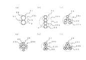
図2に内部導体2の構造に関する複数の実施形態を示す。   FIG. 2 shows a plurality of embodiments relating to the structure of the inner conductor 2.

図2(a)に比較例として示した内部導体21は、2本の素線22を撚り合わせた対撚り線23aを形成し、その対撚り線23aの1本で内部導体21を構成したものである。図示のように、内部導体21の断面は、各素線22のほぼ円形の断面が互いに接して並んだ8の字状を呈する。これにより、図示上方と下方に凸部分が形成され、左方と右方に凹部分が形成される。各素線22が撚り合わせてあるので、長手方向に位置をずらすと凹凸の角度がずれる。すなわち、内部導体21には、螺旋状の凹凸が形成される。凸部分の一番外側を結んだ線が破線αで示してある。この破線αは、凸部分に接している内部絶縁体3(図1参照)の内周である。従って、凹部分の表面と内部絶縁体3(の内周表面)との間に空隙6を生じる。   The internal conductor 21 shown as a comparative example in FIG. 2A is a wire in which two strands 22 are twisted to form a twisted pair wire 23a, and the inner conductor 21 is constituted by one of the paired twisted wires 23a. It is. As shown in the drawing, the cross section of the inner conductor 21 has an 8-shaped shape in which the substantially circular cross sections of the strands 22 are arranged in contact with each other. As a result, convex portions are formed on the upper and lower sides in the figure, and concave portions are formed on the left and right sides. Since the strands 22 are twisted together, the angle of the unevenness is shifted when the position is shifted in the longitudinal direction. That is, the inner conductor 21 is formed with spiral irregularities. A line connecting the outermost portions of the convex portions is indicated by a broken line α. This broken line α is the inner periphery of the internal insulator 3 (see FIG. 1) in contact with the convex portion. Accordingly, a gap 6 is generated between the surface of the concave portion and the inner insulator 3 (the inner peripheral surface thereof).

撚り合わせる素線22の本数が3本以上でも、撚り合わせることにより、内部絶縁体3との間に空隙6を生じさせることができる。   Even if the number of strands 22 to be twisted is three or more, the gap 6 can be generated between the internal insulator 3 by twisting together.

図2(b)〜図2(f)に示した内部導体24〜28は、複数本の素線22を撚り合わせた撚り線23(23a,23b)を複数本撚り合わせた二重撚り線29で内部導体24〜28を構成したものである。   The inner conductors 24 to 28 shown in FIGS. 2 (b) to 2 (f) are double stranded wires 29 in which a plurality of strands 23 (23 a, 23 b) in which a plurality of strands 22 are twisted together are stranded. The internal conductors 24 to 28 are configured.

図2(b)の内部導体24は、2本の素線22を撚り合わせた対撚り線23aを2本撚り合わせた二重撚り線29bで構成されている。説明の便宜上、対撚り線23aの断面を破線αのようにほぼ円形と仮定すると、対撚り線23aを撚り合わせた二重撚り線29bには螺旋状の凹凸が形成される。凸部分の一番外側を結んだ線が破線βで示してある。この破線βは、二重撚り線29bの凸部分に接している内部絶縁体3(図1参照)の内周と考えてよい。二重撚り線29bの凹部分の表面と内部絶縁体3(の内周表面)との間に空隙6を生じる。さらに、対撚り線23の断面をほぼ円形と仮定した破線αの内側には、図2(a)で説明したのと同様の空隙6が有るので、二重撚り線29bは複数の素線22の総断面積に比して空隙の総断面積が広く得られる。   The inner conductor 24 in FIG. 2B is composed of a double stranded wire 29b in which two twisted wires 23a obtained by twisting two strands 22 are twisted. For convenience of explanation, assuming that the cross-section of the twisted pair wire 23a is substantially circular as indicated by the broken line α, a spiral concavo-convex pattern is formed on the double twisted wire 29b formed by twisting the twisted pair wire 23a. A line connecting the outermost sides of the convex portion is indicated by a broken line β. This broken line β may be considered as the inner periphery of the internal insulator 3 (see FIG. 1) in contact with the convex portion of the double stranded wire 29b. A gap 6 is formed between the surface of the concave portion of the double stranded wire 29b and the inner insulator 3 (the inner peripheral surface thereof). Furthermore, since the gap 6 is the same as that described with reference to FIG. 2A inside the broken line α assuming that the cross-section of the twisted pair wire 23 is substantially circular, the double-stranded wire 29b includes a plurality of strands 22. Compared to the total cross-sectional area, the total cross-sectional area of the gap can be widely obtained.

図2(c)の内部導体25は、2本の素線22を撚り合わせた対撚り線23aを3本撚り合わせた二重撚り線29cで構成されている。   The inner conductor 25 in FIG. 2 (c) is composed of a double stranded wire 29c in which three twisted pairs 23a obtained by twisting two strands 22 are stranded.

図2(d)の内部導体26は、2本の素線22を撚り合わせた対撚り線23aを4本撚り合わせた二重撚り線29dで構成されている。   The inner conductor 26 in FIG. 2D is composed of a double stranded wire 29d in which four twisted wires 23a obtained by twisting two strands 22 are twisted.

図2(e)の内部導体27は、3本の素線22を撚り合わせた撚り線23bを2本撚り合わせた二重撚り線29eで構成されている。   The inner conductor 27 in FIG. 2 (e) is composed of a double stranded wire 29e obtained by twisting two strands 23b obtained by twisting three strands 22 together.

図2(f)の内部導体28は、3本の素線22を撚り合わせた撚り線23bを3本撚り合わせた二重撚り線29fで構成されている。   The inner conductor 28 in FIG. 2 (f) is composed of a double stranded wire 29f obtained by twisting three strands 23b obtained by twisting three strands 22 together.

図2(b)〜図2(f)には、撚りの方向を示さなかったが、二重撚り線29(29b〜29f)の撚り方向を撚り線23(23a,23b)の撚り方向とは逆方向にするのが好ましい。これは、撚り線23に生じている凹凸の捩れと反対向きに撚り線23を撚り合わせることにより、空隙6をより大きく膨らませ、かつ空隙6を保つことができるからである。   2 (b) to FIG. 2 (f) did not show the twist direction, but the twist direction of the double twisted wire 29 (29b to 29f) is the twist direction of the twisted wire 23 (23a, 23b). The reverse direction is preferred. This is because the gap 6 can be further expanded and the gap 6 can be maintained by twisting the twisted line 23 in the opposite direction to the twist of the unevenness generated in the twisted line 23.

図1に示した同軸ケーブル1は、内部導体2として図2(f)の内部導体28を用いたものである。図2(b)〜図2(e)の内部導体24〜27を用いてもよいことは言うまでもない。   The coaxial cable 1 shown in FIG. 1 uses the inner conductor 28 of FIG. Needless to say, the inner conductors 24 to 27 shown in FIGS. 2B to 2E may be used.

図1に示した同軸ケーブル1は、空隙6の断面積を内部導体2の導体断面積(=素線22の断面積の総和)の1倍よりも大きく3倍以下としたものである。   In the coaxial cable 1 shown in FIG. 1, the cross-sectional area of the air gap 6 is set to be greater than 1 and less than or equal to 3 times the conductor cross-sectional area of the inner conductor 2 (= total cross-sectional area of the strands 22).

また、図1に示した同軸ケーブル1は、シース5の直径(=同軸ケーブル1の外径)を内部導体2の直径の5倍以下としたものである。なお、内部導体2の直径とは、内部絶縁体3の内径と同じであり、内部導体21の場合、破線αの円の直径であり、内部導体24〜28の場合、破線βの円の直径である。   Further, in the coaxial cable 1 shown in FIG. 1, the diameter of the sheath 5 (= the outer diameter of the coaxial cable 1) is set to be not more than five times the diameter of the inner conductor 2. The diameter of the inner conductor 2 is the same as the inner diameter of the inner insulator 3. In the case of the inner conductor 21, the diameter of a circle indicated by a broken line α. In the case of the inner conductors 24 to 28, the diameter of a circle indicated by a broken line β. It is.

図1に示した同軸ケーブル1は、内部絶縁体3の厚さを内部導体2の直径の1/4以上1倍以下としたものである。   In the coaxial cable 1 shown in FIG. 1, the thickness of the inner insulator 3 is not less than ¼ and not more than 1 times the diameter of the inner conductor 2.

次に、図1に示した同軸ケーブル1の作用効果を述べる。   Next, the function and effect of the coaxial cable 1 shown in FIG. 1 will be described.

同軸ケーブル1は、内部絶縁体3を無発泡の充実層で構成したので、従来の発泡電線が抱えていた問題点の多くが解消される。   In the coaxial cable 1, since the inner insulator 3 is formed of a non-foamed enhancement layer, many of the problems that conventional foamed electric wires have have been solved.

同軸ケーブル1は、内部導体2の表面と内部絶縁体3との間に空隙6を設けたので、内部絶縁体3を無発泡の充実層で構成したにもかかわらず、従来の発泡電線と同等かそれ以上又は大きく劣らない電気特性が得られる。これは、空隙6があることにより、低誘電率部材である空気が内外導体間に介在することが確保されるからである。   The coaxial cable 1 is provided with a gap 6 between the surface of the inner conductor 2 and the inner insulator 3, so that the inner insulator 3 is equivalent to a conventional foamed electric wire despite the fact that the inner insulator 3 is composed of a non-foamed solid layer. Electrical characteristics that are not less than or greater than that are obtained. This is because the presence of the gap 6 ensures that air, which is a low dielectric constant member, is interposed between the inner and outer conductors.

同軸ケーブル1は、内部導体2に螺旋状の凹凸があるため、空隙6が規則的な形状となり、気泡のような不均一性の問題がない。   In the coaxial cable 1, since the inner conductor 2 has spiral irregularities, the gap 6 has a regular shape, and there is no problem of nonuniformity such as bubbles.

同軸ケーブル1は、空隙6の断面積が内部導体2の導体断面積の1倍よりも大きいので、低静電容量化の効果が十分に得られる。このことは後述の実施例により実証する。   In the coaxial cable 1, since the cross-sectional area of the gap 6 is larger than one conductor cross-sectional area of the internal conductor 2, the effect of reducing the electrostatic capacity can be sufficiently obtained. This is demonstrated by the examples described below.

また、同軸ケーブル1は、空隙6の断面積が内部導体2の導体断面積の3倍以下であるので、内部絶縁体3が潰れにくい。もし、空隙6の断面積が内部導体2の導体断面積の3倍を超えると、同軸ケーブルの機械特性が悪影響を受け、内部絶縁体3が潰れやすくなって、所望の低静電容量化が実現できないと思われる。   Moreover, since the cross-sectional area of the space | gap 6 is 3 times or less of the conductor cross-sectional area of the internal conductor 2, the coaxial cable 1 has the internal insulator 3 hard to be crushed. If the cross-sectional area of the gap 6 exceeds three times the conductor cross-sectional area of the internal conductor 2, the mechanical characteristics of the coaxial cable are adversely affected, the internal insulator 3 is easily crushed, and a desired low capacitance can be achieved. It seems that it cannot be realized.

同軸ケーブル1は、ケーブルの細径化のため、シース5の外径(同軸ケーブルの直径)が内部導体2の直径の5倍以下とする。   In the coaxial cable 1, the outer diameter of the sheath 5 (the diameter of the coaxial cable) is set to be not more than five times the diameter of the inner conductor 2 in order to reduce the diameter of the cable.

同軸ケーブル1は、内部絶縁体3の厚さが内部導体2の直径の1/4以上あるため、内部絶縁体3が潰れにくい。逆に、内部絶縁体3の厚さが内部導体2の直径の1/4未満であると、内部絶縁体3が潰れやすく、耐電圧特性と絶縁抵抗が低下すると共に、内部導体2との間に空隙6を安定して確保しにくい。また、内部絶縁体3の厚さが内部導体2の直径の1倍以下としたので、ケーブルの細径化に寄与する。   In the coaxial cable 1, since the thickness of the internal insulator 3 is not less than ¼ of the diameter of the internal conductor 2, the internal insulator 3 is not easily crushed. Conversely, if the thickness of the internal insulator 3 is less than ¼ of the diameter of the internal conductor 2, the internal insulator 3 is liable to be crushed, the withstand voltage characteristic and the insulation resistance are lowered, and It is difficult to secure the gap 6 stably. Moreover, since the thickness of the internal insulator 3 is set to be not more than 1 times the diameter of the internal conductor 2, it contributes to the reduction of the cable diameter.

同軸ケーブル1は、二重撚り線29の撚り方向を撚り線23の撚り方向とは逆方向にしたので、空隙6をより大きく膨らませることができる。逆に、二重撚り線29の撚り方向が撚り線23の撚り方向と同じであると、撚り形状が重なり合って空隙6を作りにくい。   In the coaxial cable 1, since the twist direction of the double stranded wire 29 is opposite to the twist direction of the stranded wire 23, the gap 6 can be expanded more greatly. On the contrary, when the twist direction of the double stranded wire 29 is the same as the twist direction of the stranded wire 23, the twist shapes overlap and it is difficult to make the gap 6.

同軸ケーブル1は、内部導体2の真ん中に撚られない素線22がないように複数の素線22を撚ったので、あるいは二重撚り線にしたので、応力が集中しやすい真ん中の素線がなくなり、屈曲特性が良くなる。   The coaxial cable 1 has a plurality of strands 22 twisted so that there is no strand 22 untwisted in the middle of the inner conductor 2, or a double strand, so that the middle strand where stress tends to concentrate And bending characteristics are improved.

次に、図2(b)〜図2(f)の各内部導体21〜28を用いたことによる同軸ケーブル1の効果の違いを述べる。   Next, the difference in the effect of the coaxial cable 1 due to the use of the inner conductors 21 to 28 of FIGS. 2B to 2F will be described.

低静電容量化の効果の大きい順番は次の通りである。   The order in which the effect of lowering the capacitance is large is as follows.

図2(a)<図2(f)<図2(d)<図2(e)=図2(c)<図2(b)
つまり、図2(b)の内部導体24を用いた同軸ケーブル1が最も静電容量が小さい。
2 (a) <FIG. 2 (f) <FIG. 2 (d) <FIG. 2 (e) = FIG. 2 (c) <FIG. 2 (b)
That is, the coaxial cable 1 using the inner conductor 24 of FIG.

内部絶縁体3との間に安定した空隙6を作りやすい順番は次の通りである。   The order in which a stable air gap 6 can be easily formed with the internal insulator 3 is as follows.

図2(a)=図2(b)=図2(e)<図2(d)<図2(c)=図2(f)
つまり、図2(c)の内部導体25と図2(f)の内部導体28が最も安定した空隙6を作りやすい。
2 (a) = FIG. 2 (b) = FIG. 2 (e) <FIG. 2 (d) <FIG. 2 (c) = FIG. 2 (f)
That is, the inner conductor 25 in FIG. 2C and the inner conductor 28 in FIG.

機械特性がよい順番は次の通りである。   The order of good mechanical properties is as follows.

図2(a)<図2(b)<図2(d)<図2(e)<図2(c)<図2(b)
つまり、図2(f)の内部導体28を用いた同軸ケーブル1が最も機械特性がよい。
2 (a) <FIG. 2 (b) <FIG. 2 (d) <FIG. 2 (e) <FIG. 2 (c) <FIG. 2 (b)
That is, the coaxial cable 1 using the inner conductor 28 of FIG.

以上を総合すると、低静電容量化の効果が大きく、安定した空隙6を作りやすく、しかも機械特性が高い同軸ケーブル1をもたらす内部導体は、図2(c)の内部導体25である。   To sum up the above, the inner conductor 25 that has the effect of lowering the capacitance, easily forms a stable gap 6 and provides the coaxial cable 1 with high mechanical properties is the inner conductor 25 in FIG.

次に、本発明に係る多心ケーブルについて説明する。   Next, the multi-core cable according to the present invention will be described.

図3〜図5に示す本発明の多心ケーブルは、これまで説明した同軸ケーブルを複数本有するものである。   The multi-core cable of the present invention shown in FIGS. 3 to 5 has a plurality of coaxial cables described so far.

図3に示した多心ケーブル31は、中心介在及びテンションメンバ32の回りに図1の同軸ケーブル1を4本束ねた同軸ケーブル束33を形成し、その同軸ケーブル束33をバインドテープ(押し巻きテープとも言う)34で巻き、そのバインドテープ34の外周にシールド35を設け、そのシールド35を外装シース36で覆ったものである。同軸ケーブル束33に含める同軸ケーブル1の本数は4本に限らず、2本以上何本でも良い。   A multi-core cable 31 shown in FIG. 3 forms a coaxial cable bundle 33 in which four coaxial cables 1 of FIG. 1 are bundled around a central intervention and tension member 32, and the coaxial cable bundle 33 is bound with a binding tape (push-wrapped). The shield 35 is wound around the outer periphery of the bind tape 34, and the shield 35 is covered with an outer sheath 36. The number of coaxial cables 1 included in the coaxial cable bundle 33 is not limited to four, and may be any number of two or more.

バインドテープ34の巻き厚は例えば0.1mmである。シールド35は、例えば、厚さが0.08mmであり、Snめっき軟鋼線編線である。横巻きシールドでも良い。外装シース36は、PETテープを巻き回したり、ビニル(PVC)、四フッ化エチレン・パーフロロプロピルビニルエーテル共重合体(PFA)、四フッ化エチレン・六フッ化プロピレン共重合体(FEP)、エチレン・四フッ化エチレン共重合体(ETFE)を押出被覆したりして形成する。   The winding thickness of the bind tape 34 is 0.1 mm, for example. The shield 35 has, for example, a thickness of 0.08 mm and is a Sn-plated mild steel knitted wire. Horizontal winding shield may be used. The outer sheath 36 is formed by winding a PET tape, vinyl (PVC), tetrafluoroethylene / perfluoropropyl vinyl ether copolymer (PFA), tetrafluoroethylene / hexafluoropropylene copolymer (FEP), ethylene -It is formed by extrusion coating a tetrafluoroethylene copolymer (ETFE).

図4に示した多心ケーブル41は、図1の同軸ケーブル1を12本束ねた同軸ケーブル束42を形成し、その同軸ケーブル束42を4本、中心介在及びテンションメンバ43の回りに撚り合わせ、この撚り合わせたものをバインドテープ44で巻き、そのバインドテープ44の外周にシールド45を設け、そのシールド45を外装シース46で覆ったものである。撚り合わせる同軸ケーブル束42の本数は4本に限らず、2本以上何本でも良い。   The multi-core cable 41 shown in FIG. 4 forms a coaxial cable bundle 42 in which 12 coaxial cables 1 of FIG. 1 are bundled, and four coaxial cable bundles 42 are twisted around the central interposition and the tension member 43. The twisted one is wound with a bind tape 44, a shield 45 is provided on the outer periphery of the bind tape 44, and the shield 45 is covered with an outer sheath 46. The number of coaxial cable bundles 42 to be twisted is not limited to four, and may be any number of two or more.

図5に示した多心ケーブル51は、図1の同軸ケーブル1を任意の整数本、平行に並べてリボン状にしたものである。同軸ケーブル1は一定のピッチで配置し、同軸ケーブル1の下面と上面にそれぞれ粘着テープ52を貼り付けることにより、全体を一体化してリボンケーブルにする。   A multi-core cable 51 shown in FIG. 5 is obtained by arranging arbitrary numbers of coaxial cables 1 in FIG. 1 in parallel to form a ribbon. The coaxial cable 1 is arranged at a constant pitch, and the adhesive tape 52 is attached to each of the lower surface and the upper surface of the coaxial cable 1 so that the whole is integrated into a ribbon cable.

これらの多心ケーブル31,41,51は、同軸ケーブル1が細径化されているため、多心ケーブル31,41,51も細径化される。   Since the coaxial cable 1 has a reduced diameter, the multi-core cables 31, 41, 51 are also reduced in diameter.

実施例1;対撚り線を3本撚り
素線22として直径0.033mmのSnめっき銅合金線を2本用意し、これら素線22をピッチ0.5〜1.0mmで対撚りした。その対撚り線23aを3本用意し、これら対撚り線23aを対撚り線23aの撚り方向とは逆方向に集合撚りして外径が0.142mmの二重撚り線29cを作製し、内部導体25とした。この内部導体25の外周に厚さ0.089mmのPFA樹脂を押出被覆して外径0.320mm、内径0.142mmの無発泡な充実層である内部絶縁体3を形成した。この内部絶縁体3の外周に素線径が0.025mmのSnめっき銅合金線を横巻きして外部導体4を形成し、その外部導体4の外周に厚さ0.02mmのPET樹脂からなるシース5を被覆して、外径0.410mmの同軸ケーブル1を得た。
Example 1: Three twisted pair wires were twisted. Two Sn-plated copper alloy wires having a diameter of 0.033 mm were prepared as the strands 22, and these strands 22 were twisted at a pitch of 0.5 to 1.0 mm. Three such twisted wires 23a are prepared, and these twisted wires 23a are collectively twisted in the direction opposite to the twisted direction of the twisted wires 23a to produce a double twisted wire 29c having an outer diameter of 0.142 mm. A conductor 25 was obtained. The inner conductor 3 which is a non-foamed solid layer having an outer diameter of 0.320 mm and an inner diameter of 0.142 mm was formed by extrusion-coating a PFA resin having a thickness of 0.089 mm on the outer periphery of the inner conductor 25. An outer conductor 4 is formed by horizontally winding an Sn-plated copper alloy wire having a wire diameter of 0.025 mm on the outer periphery of the inner insulator 3, and the outer conductor 4 is made of PET resin having a thickness of 0.02 mm. The sheath 5 was covered to obtain a coaxial cable 1 having an outer diameter of 0.410 mm.

このとき、内部導体2の導体断面積、すなわち素線22の総断面積が0.00513mm2であり、内部導体2と内部絶縁体3との隙間からなる空隙6の断面積が0.0108mm2であり、よって、空隙6の断面積が内部導体2の導体断面積の約2.1倍、つまり1倍よりも大きく3倍以下であった。同軸ケーブル1の外径0.410mmは内部導体2の直径0.142mmの5倍以下、内部絶縁体3の厚さ0.089mmは内部導体2の直径0.142mmの1/4以上1倍以下であった。
実施例2;対撚り線を3本撚り
素線22として直径0.027mmのSnめっき銅合金線を2本用意し、これら素線22をピッチ0.4〜0.8mmで対撚りした。その対撚り線23aを3本用意し、これら対撚り線23aを対撚り線23aの撚り方向とは逆方向に集合撚りして外径が0.117mmの二重撚り線29cを作製し、内部導体25とした。この内部導体25の外周に厚さ0.072mmのPFA樹脂を押出被覆して外径0.260mm、内径0.117mmの無発泡な充実層である内部絶縁体3を形成した。この内部絶縁体3の外周に素線径が0.025mmのSnめっき銅合金線を横巻きして外部導体4を形成し、その外部導体4の外周に厚さ0.02mmのPET樹脂からなるシース5を被覆して、外径0.351mmの同軸ケーブル1を得た。
At this time, the conductor sectional area of the inner conductor 2, that is, the total sectional area of the strands 22 is 0.00513 mm 2 , and the sectional area of the gap 6 formed by the gap between the inner conductor 2 and the inner insulator 3 is 0.0108 mm 2. Therefore, the cross-sectional area of the air gap 6 was about 2.1 times the conductor cross-sectional area of the inner conductor 2, that is, greater than 1 time and less than 3 times. The outer diameter 0.410 mm of the coaxial cable 1 is 5 times or less of the diameter 0.142 mm of the inner conductor 2, and the thickness of the inner insulator 3 is 0.089 mm or more and ¼ to 1 times the diameter of the inner conductor 2 0.142 mm. Met.
Example 2: Three twisted wires were twisted Two Sn-plated copper alloy wires having a diameter of 0.027 mm were prepared as the strands 22, and these strands 22 were twisted at a pitch of 0.4 to 0.8 mm. Three twisted wires 23a are prepared, and these twisted wires 23a are collectively twisted in a direction opposite to the twisted direction of the twisted wires 23a to produce a double twisted wire 29c having an outer diameter of 0.117 mm. A conductor 25 was obtained. An inner insulator 3 which is a non-foamed solid layer having an outer diameter of 0.260 mm and an inner diameter of 0.117 mm was formed by extrusion coating a PFA resin having a thickness of 0.072 mm on the outer periphery of the inner conductor 25. An outer conductor 4 is formed by horizontally winding an Sn-plated copper alloy wire having a wire diameter of 0.025 mm on the outer periphery of the inner insulator 3, and the outer conductor 4 is made of PET resin having a thickness of 0.02 mm. The sheath 5 was covered to obtain a coaxial cable 1 having an outer diameter of 0.351 mm.

このとき、内部導体2の導体断面積が0.00343mm2であり、空隙6の断面積が0.00725mm2であり、よって、空隙6の断面積が内部導体2の導体断面積の約2.1倍、つまり1倍よりも大きく3倍以下であった。同軸ケーブル1の外径0.351mmは内部導体2の直径0.117mmの5倍以下、内部絶縁体3の厚さ0.072mmは内部導体2の直径0.117mmの1/4以上1倍以下であった。
実施例3;対撚り線を3本撚り
素線22として直径0.025mmのSnめっき銅合金線を2本用意し、これら素線22をピッチ0.4〜0.8mmで対撚りした。その対撚り線23aを3本用意し、これら対撚り線23aを対撚り線23aの撚り方向とは逆方向に集合撚りして外径が0.107mmの二重撚り線29cを作製し、内部導体25とした。この内部導体25の外周に厚さ0.061mmのPFA樹脂を押出被覆して外径0.229mm、内径0.107mmの無発泡な充実層である内部絶縁体3を形成した。この内部絶縁体3の外周に素線径が0.025mmのSnめっき銅合金線を横巻きして外部導体4を形成し、その外部導体4の外周に厚さ0.015mmのPET樹脂からなるシース5を被覆して、外径0.309mmの同軸ケーブル1を得た。
At this time, the conductor cross-sectional area of the inner conductor 2 is 0.00343 mm 2 , and the cross-sectional area of the gap 6 is 0.00725 mm 2 , so that the cross-sectional area of the gap 6 is about 2. It was 1 time, that is, more than 1 time and 3 times or less. The outer diameter of the coaxial cable 1 is not more than 5 times the diameter of the inner conductor 2, and the thickness of the inner insulator 3 is not less than 1/4 times the diameter of the inner conductor 2, 0.117 mm. Met.
Example 3: Three twisted wires were twisted Two Sn-plated copper alloy wires having a diameter of 0.025 mm were prepared as the strands 22, and these strands 22 were twisted at a pitch of 0.4 to 0.8 mm. Three such twisted wires 23a are prepared, and these twisted wires 23a are collectively twisted in the direction opposite to the twisted direction of the twisted wires 23a to produce a double twisted wire 29c having an outer diameter of 0.107 mm. A conductor 25 was obtained. A PFA resin having a thickness of 0.061 mm was extrusion coated on the outer periphery of the inner conductor 25 to form an inner insulator 3 that is a non-foamed solid layer having an outer diameter of 0.229 mm and an inner diameter of 0.107 mm. An outer conductor 4 is formed by horizontally winding an Sn-plated copper alloy wire having a strand diameter of 0.025 mm on the outer periphery of the inner insulator 3, and the outer conductor 4 is made of PET resin having a thickness of 0.015 mm. The sheath 5 was covered to obtain a coaxial cable 1 having an outer diameter of 0.309 mm.

このとき、内部導体2の導体断面積が0.00295mm2であり、空隙6の断面積が0.00621mm2であり、よって、空隙6の断面積が内部導体2の導体断面積の約2.1倍、つまり1倍よりも大きく3倍以下であった。同軸ケーブル1の外径0.309mmは内部導体2の直径0.107mmの5倍以下、内部絶縁体3の厚さ0.061mmは内部導体2の直径0.107mmの1/4以上1倍以下であった。
実施例4;対撚り線を3本撚り
素線22として直径0.022mmのSnめっき銅合金線を2本用意し、これら素線22をピッチ0.3〜0.7mmで対撚りした。その対撚り線23aを3本用意し、これら対撚り線23aを対撚り線23aの撚り方向とは逆方向に集合撚りして外径が0.093mmの二重撚り線29cを作製し、内部導体25とした。この内部導体25の外周に厚さ0.051mmのPFA樹脂を押出被覆して外径0.195mm、内径0.093mmの無発泡な充実層である内部絶縁体3を形成した。この内部絶縁体3の外周に素線径が0.025mmのSnめっき銅合金線を横巻きして外部導体4を形成し、その外部導体4の外周に厚さ0.015mmのPET樹脂からなるシース5を被覆して、外径0.275mmの同軸ケーブル1を得た。
At this time, the conductor cross-sectional area of the inner conductor 2 is 0.00295 mm 2 , and the cross-sectional area of the gap 6 is 0.00621 mm 2 , so that the cross-sectional area of the gap 6 is about 2. It was 1 time, that is, more than 1 time and 3 times or less. The outer diameter of the coaxial cable 1 is 0.309 mm is 5 times or less than the diameter 0.107 mm of the inner conductor 2, and the thickness of the inner insulator 3 is 0.061 mm or more is ¼ to 1 times the inner conductor 2 diameter 0.107 mm. Met.
Example 4: Three twisted wires were twisted Two Sn-plated copper alloy wires having a diameter of 0.022 mm were prepared as the strands 22, and these strands 22 were twisted at a pitch of 0.3 to 0.7 mm. Three twisted wires 23a are prepared, and these twisted wires 23a are collectively twisted in a direction opposite to the twisted direction of the twisted wires 23a to produce a double twisted wire 29c having an outer diameter of 0.093 mm. A conductor 25 was obtained. An inner insulator 3 which is a non-foamed solid layer having an outer diameter of 0.195 mm and an inner diameter of 0.093 mm was formed by extrusion coating a 0.051 mm thick PFA resin on the outer periphery of the inner conductor 25. An outer conductor 4 is formed by horizontally winding an Sn-plated copper alloy wire having a strand diameter of 0.025 mm on the outer periphery of the inner insulator 3, and the outer conductor 4 is made of PET resin having a thickness of 0.015 mm. The sheath 5 was covered to obtain a coaxial cable 1 having an outer diameter of 0.275 mm.

このとき、内部導体2の導体断面積が0.00228mm2であり、空隙6の断面積が0.0048mm2であり、よって、空隙6の断面積が内部導体2の導体断面積の約2.1倍、つまり1倍よりも大きく3倍以下であった。同軸ケーブル1の外径0.275mmは内部導体2の直径0.093mmの5倍以下、内部絶縁体3の厚さ0.051mmは内部導体2の直径0.093mmの1/4以上1倍以下であった。
実施例5;対撚り線を3本撚り
素線22として直径0.019mmのSnめっき銅合金線を2本用意し、これら素線22をピッチ0.3〜0.6mmで対撚りした。その対撚り線23aを3本用意し、これら対撚り線23aを対撚り線23aの撚り方向とは逆方向に集合撚りして外径が0.084mmの二重撚り線29cを作製し、内部導体25とした。この内部導体25の外周に厚さ0.048mmのPFA樹脂を押出被覆して外径0.18mm、内径0.084mmの無発泡な充実層である内部絶縁体3を形成した。この内部絶縁体3の外周に素線径が0.02mmのSnめっき銅合金線を横巻きして外部導体4を形成し、その外部導体4の外周に厚さ0.015mmのPET樹脂からなるシース5を被覆して、外径0.250mmの同軸ケーブル1を得た。
At this time, the conductor cross-sectional area of the inner conductor 2 is 0.00228 mm 2 , and the cross-sectional area of the gap 6 is 0.0048 mm 2 , so that the cross-sectional area of the gap 6 is approximately 2 times the conductor cross-sectional area of the inner conductor 2. It was 1 time, that is, more than 1 time and 3 times or less. The outer diameter 0.275 mm of the coaxial cable 1 is 5 times or less of the diameter 0.093 mm of the inner conductor 2, and the thickness of the inner insulator 3 is 0.05 to 1 times the diameter 0.093 mm of the inner conductor 2. Met.
Example 5: Three twisted pairs of strands Two strands of Sn-plated copper alloy wire having a diameter of 0.019 mm were prepared as the strands 22, and these strands 22 were twisted at a pitch of 0.3 to 0.6 mm. Three such twisted wires 23a are prepared, and these twisted wires 23a are collectively twisted in a direction opposite to the twisted direction of the twisted wires 23a to produce a double twisted wire 29c having an outer diameter of 0.084 mm. A conductor 25 was obtained. An inner insulator 3 which is a non-foamed solid layer having an outer diameter of 0.18 mm and an inner diameter of 0.084 mm was formed by extrusion-coating a PFA resin having a thickness of 0.048 mm on the outer periphery of the inner conductor 25. An outer conductor 4 is formed by laterally winding an Sn-plated copper alloy wire having a strand diameter of 0.02 mm on the outer periphery of the inner insulator 3, and the outer conductor 4 is made of PET resin having a thickness of 0.015 mm. The sheath 5 was covered to obtain a coaxial cable 1 having an outer diameter of 0.250 mm.

このとき、内部導体2の導体断面積が0.00177mm2であり、空隙6の断面積が0.00377mm2であり、よって、空隙6の断面積が内部導体2の導体断面積の約2.1倍、つまり1倍よりも大きく3倍以下であった。同軸ケーブル1の外径0.250mmは内部導体2の直径0.084mmの5倍以下、内部絶縁体3の厚さ0.048mmは内部導体2の直径0.084mmの1/4以上1倍以下であった。
実施例6;対撚り線を3本撚り
素線22として直径0.017mmのSnめっき銅合金線を2本用意し、これら素線22をピッチ0.3〜0.5mmで対撚りした。その対撚り線23aを3本用意し、これら対撚り線23aを対撚り線23aの撚り方向とは逆方向に集合撚りして外径が0.074mmの二重撚り線29cを作製し、内部導体25とした。この内部導体25の外周に厚さ0.038mmのPFA樹脂を押出被覆して外径0.15mm、内径0.074mmの無発泡な充実層である内部絶縁体3を形成した。この内部絶縁体3の外周に素線径が0.02mmのSnめっき銅合金線を横巻きして外部導体4を形成し、その外部導体4の外周に厚さ0.015mmのPET樹脂からなるシース5を被覆して、外径0.22mmの同軸ケーブル1を得た。
At this time, the conductor cross-sectional area of the inner conductor 2 is 0.00177 mm 2 , and the cross-sectional area of the gap 6 is 0.00377 mm 2 , so that the cross-sectional area of the gap 6 is about 2. It was 1 time, that is, more than 1 time and 3 times or less. The outer diameter 0.250 mm of the coaxial cable 1 is 5 times or less of the diameter 0.084 mm of the inner conductor 2, and the thickness of the inner insulator 3 is 0.048 mm or more and ¼ to 1 time of the inner conductor 2 diameter 0.084 mm. Met.
Example 6: Three twisted wires were twisted Two Sn-plated copper alloy wires having a diameter of 0.017 mm were prepared as the wires 22, and the wires 22 were twisted at a pitch of 0.3 to 0.5 mm. Three twisted wires 23a are prepared, and these twisted wires 23a are collectively twisted in a direction opposite to the twisted direction of the twisted wires 23a to produce a double twisted wire 29c having an outer diameter of 0.074 mm. A conductor 25 was obtained. An inner insulator 3 which is a non-foamed solid layer having an outer diameter of 0.15 mm and an inner diameter of 0.074 mm was formed by extrusion-coating a PFA resin having a thickness of 0.038 mm on the outer periphery of the inner conductor 25. An outer conductor 4 is formed by laterally winding an Sn-plated copper alloy wire having a strand diameter of 0.02 mm on the outer periphery of the inner insulator 3, and the outer conductor 4 is made of PET resin having a thickness of 0.015 mm. The sheath 5 was covered to obtain a coaxial cable 1 having an outer diameter of 0.22 mm.

このとき、内部導体2の導体断面積が0.00136mm2であり、空隙6の断面積が0.00286mm2であり、よって、空隙6の断面積が内部導体2の導体断面積の約2.1倍、つまり1倍よりも大きく3倍以下であった。同軸ケーブル1の外径0.250mmは内部導体2の直径0.084mmの5倍以下、内部絶縁体3の厚さ0.048mmは内部導体2の直径0.084mmの1/4以上1倍以下であった。
実施例7;対撚り線を4本撚り
素線22として直径0.028mmのSnめっき銅合金線を2本用意し、これら素線22をピッチ0.4〜0.9mmで対撚りした。その対撚り線23aを4本用意し、これら対撚り線23aを対撚り線23aの撚り方向とは逆方向に集合撚りして外径が0.135mmの二重撚り線29dを作製し、内部導体26とした。この内部導体26の外周に厚さ0.093mmのPFA樹脂を押出被覆して外径0.320mm、内径0.135mmの無発泡な充実層である内部絶縁体3を形成した。この内部絶縁体3の外周に素線径が0.025mmのSnめっき銅合金線を横巻きして外部導体4を形成し、その外部導体4の外周に厚さ0.02mmのPET樹脂からなるシース5を被覆して、外径0.410mmの同軸ケーブル1を得た。
At this time, the conductor cross-sectional area of the inner conductor 2 is 0.00136 mm 2 , and the cross-sectional area of the gap 6 is 0.00286 mm 2 , so that the cross-sectional area of the gap 6 is approximately 2 times the conductor cross-sectional area of the inner conductor 2. It was 1 time, that is, more than 1 time and 3 times or less. The outer diameter 0.250 mm of the coaxial cable 1 is 5 times or less of the diameter 0.084 mm of the inner conductor 2, and the thickness of the inner insulator 3 is 0.048 mm or more and ¼ to 1 time of the inner conductor 2 diameter 0.084 mm. Met.
Example 7: Four twisted wires were twisted Two Sn-plated copper alloy wires having a diameter of 0.028 mm were prepared as the strands 22, and these strands 22 were twisted at a pitch of 0.4 to 0.9 mm. Four such twisted wires 23a are prepared, and these twisted wires 23a are collectively twisted in a direction opposite to the twisted direction of the twisted wires 23a to produce a double twisted wire 29d having an outer diameter of 0.135 mm. A conductor 26 was obtained. A PFA resin having a thickness of 0.093 mm was extrusion coated on the outer periphery of the inner conductor 26 to form the inner insulator 3 as a non-foamed solid layer having an outer diameter of 0.320 mm and an inner diameter of 0.135 mm. An outer conductor 4 is formed by horizontally winding an Sn-plated copper alloy wire having a wire diameter of 0.025 mm on the outer periphery of the inner insulator 3, and the outer conductor 4 is made of PET resin having a thickness of 0.02 mm. The sheath 5 was covered to obtain a coaxial cable 1 having an outer diameter of 0.410 mm.

このとき、内部導体2の導体断面積が0.00493mm2であり、空隙6の断面積が0.00938mm2であり、よって、空隙6の断面積が内部導体2の導体断面積の約1.90倍、つまり1倍よりも大きく3倍以下であった。同軸ケーブル1の外径0.410mmは内部導体2の直径0.135mmの5倍以下、内部絶縁体3の厚さ0.093mmは内部導体2の直径0.135mmの1/4以上1倍以下であった。
実施例8;対撚り線を4本撚り
素線22として直径0.023mmのSnめっき銅合金線を2本用意し、これら素線22をピッチ0.3〜0.7mmで対撚りした。その対撚り線23aを4本用意し、これら対撚り線23aを対撚り線23aの撚り方向とは逆方向に集合撚りして外径が0.111mmの二重撚り線29dを作製し、内部導体26とした。この内部導体26の外周に厚さ0.075mmのPFA樹脂を押出被覆して外径0.260mm、内径0.111mmの無発泡な充実層である内部絶縁体3を形成した。この内部絶縁体3の外周に素線径が0.025mmのSnめっき銅合金線を横巻きして外部導体4を形成し、その外部導体4の外周に厚さ0.02mmのPET樹脂からなるシース5を被覆して、外径0.351mmの同軸ケーブル1を得た。
At this time, the conductor cross-sectional area of the inner conductor 2 is 0.00493 mm 2 , and the cross-sectional area of the gap 6 is 0.00938 mm 2 . 90 times, that is, more than 1 time and 3 times or less. The outer diameter 0.410 mm of the coaxial cable 1 is 5 times or less of the diameter 0.135 mm of the inner conductor 2, and the thickness of the inner insulator 3 is 0.093 mm or more and ¼ or more of the inner conductor 2 diameter 0.135 mm. Met.
Example 8: Four twisted wires were twisted Two Sn-plated copper alloy wires having a diameter of 0.023 mm were prepared as the strands 22, and these strands 22 were twisted at a pitch of 0.3 to 0.7 mm. Four such twisted wires 23a are prepared, and these twisted wires 23a are collectively twisted in a direction opposite to the twisted direction of the twisted wires 23a to produce a double twisted wire 29d having an outer diameter of 0.111 mm. A conductor 26 was obtained. An inner insulator 3 which is a non-foamed solid layer having an outer diameter of 0.260 mm and an inner diameter of 0.111 mm was formed by extrusion-coating a PFA resin having a thickness of 0.075 mm on the outer periphery of the inner conductor 26. An outer conductor 4 is formed by horizontally winding an Sn-plated copper alloy wire having a wire diameter of 0.025 mm on the outer periphery of the inner insulator 3, and the outer conductor 4 is made of PET resin having a thickness of 0.02 mm. The sheath 5 was covered to obtain a coaxial cable 1 having an outer diameter of 0.351 mm.

このとき、内部導体2の導体断面積が0.00333mm2であり、空隙6の断面積が0.00634mm2であり、よって、空隙6の断面積が内部導体2の導体断面積の約1.90倍、つまり1倍よりも大きく3倍以下であった。同軸ケーブル1の外径0.351mmは内部導体2の直径0.111mmの5倍以下、内部絶縁体3の厚さ0.075mmは内部導体2の直径0.111mmの1/4以上1倍以下であった。
実施例9;対撚り線を4本撚り
素線22として直径0.021mmのSnめっき銅合金線を2本用意し、これら素線22をピッチ0.3〜0.7mmで対撚りした。その対撚り線23aを4本用意し、これら対撚り線23aを対撚り線23aの撚り方向とは逆方向に集合撚りして外径が0.102mmの二重撚り線29dを作製し、内部導体26とした。この内部導体26の外周に厚さ0.064mmのPFA樹脂を押出被覆して外径0.229mm、内径0.102mmの無発泡な充実層である内部絶縁体3を形成した。この内部絶縁体3の外周に素線径が0.025mmのSnめっき銅合金線を横巻きして外部導体4を形成し、その外部導体4の外周に厚さ0.015mmのPET樹脂からなるシース5を被覆して、外径0.310mmの同軸ケーブル1を得た。
At this time, the conductor cross-sectional area of the inner conductor 2 is 0.00333 mm 2 , and the cross-sectional area of the gap 6 is 0.00634 mm 2 , so that the cross-sectional area of the gap 6 is about 1. 90 times, that is, more than 1 time and 3 times or less. The outer diameter of the coaxial cable 1 is not more than 5 times the diameter of the inner conductor 2, and the thickness of the inner insulator 3 is not less than ¼ and less than 1 times the diameter of the inner conductor 2, 0.111 mm. Met.
Example 9: Four twisted wires were twisted Two Sn-plated copper alloy wires having a diameter of 0.021 mm were prepared as the strands 22, and these strands 22 were twisted at a pitch of 0.3 to 0.7 mm. Four such twisted wires 23a are prepared, and these twisted wires 23a are collectively twisted in a direction opposite to the twisted direction of the twisted wires 23a to produce a double twisted wire 29d having an outer diameter of 0.102 mm. A conductor 26 was obtained. An inner insulator 3 which is a non-foamed solid layer having an outer diameter of 0.229 mm and an inner diameter of 0.102 mm was formed by extrusion-coating a PFA resin having a thickness of 0.064 mm on the outer periphery of the inner conductor 26. An outer conductor 4 is formed by horizontally winding an Sn-plated copper alloy wire having a strand diameter of 0.025 mm on the outer periphery of the inner insulator 3, and the outer conductor 4 is made of PET resin having a thickness of 0.015 mm. The sheath 5 was covered to obtain a coaxial cable 1 having an outer diameter of 0.310 mm.

このとき、内部導体2の導体断面積が0.00277mm2であり、空隙6の断面積が0.00540mm2であり、よって、空隙6の断面積が内部導体2の導体断面積の約1.95倍、つまり1倍よりも大きく3倍以下であった。同軸ケーブル1の外径0.310mmは内部導体2の直径0.102mmの5倍以下、内部絶縁体3の厚さ0.064mmは内部導体2の直径0.102mmの1/4以上1倍以下であった。
実施例10;対撚り線を4本撚り
素線22として直径0.019mmのSnめっき銅合金線を2本用意し、これら素線22をピッチ0.3〜0.6mmで対撚りした。その対撚り線23aを4本用意し、これら対撚り線23aを対撚り線23aの撚り方向とは逆方向に集合撚りして外径が0.092mmの二重撚り線29dを作製し、内部導体26とした。この内部導体26の外周に厚さ0.052mmのPFA樹脂を押出被覆して外径0.195mm、内径0.092mmの無発泡な充実層である内部絶縁体3を形成した。この内部絶縁体3の外周に素線径が0.025mmのSnめっき銅合金線を横巻きして外部導体4を形成し、その外部導体4の外周に厚さ0.015mmのPET樹脂からなるシース5を被覆して、外径0.280mmの同軸ケーブル1を得た。
At this time, the conductor cross-sectional area of the inner conductor 2 is 0.00277 mm 2 , and the cross-sectional area of the gap 6 is 0.00540 mm 2 , so that the cross-sectional area of the gap 6 is about 1. It was 95 times, that is, more than 1 time and 3 times or less. The outer diameter 0.310 mm of the coaxial cable 1 is 5 times or less of the diameter 0.102 mm of the inner conductor 2, and the thickness of the inner insulator 3 0.064 mm is not less than 1/4 and less than 1 time of the inner conductor 2 diameter 0.102 mm. Met.
Example 10: Four twisted wires were twisted Two Sn-plated copper alloy wires having a diameter of 0.019 mm were prepared as the strands 22, and these strands 22 were twisted at a pitch of 0.3 to 0.6 mm. Four such twisted wires 23a are prepared, and these twisted wires 23a are collectively twisted in a direction opposite to the twisted direction of the twisted wires 23a to produce a double twisted wire 29d having an outer diameter of 0.092 mm. A conductor 26 was obtained. A PFA resin having a thickness of 0.052 mm was extrusion coated on the outer periphery of the inner conductor 26 to form an inner insulator 3 that is a non-foamed solid layer having an outer diameter of 0.195 mm and an inner diameter of 0.092 mm. An outer conductor 4 is formed by horizontally winding an Sn-plated copper alloy wire having a strand diameter of 0.025 mm on the outer periphery of the inner insulator 3, and the outer conductor 4 is made of PET resin having a thickness of 0.015 mm. The sheath 5 was covered to obtain a coaxial cable 1 having an outer diameter of 0.280 mm.

このとき、内部導体2の導体断面積が0.00277mm2であり、空隙6の断面積が0.00437mm2であり、よって、空隙6の断面積が内部導体2の導体断面積の約1.93倍、つまり1倍よりも大きく3倍以下であった。同軸ケーブル1の外径0.280mmは内部導体2の直径0.092mmの5倍以下、内部絶縁体3の厚さ0.052mmは内部導体2の直径0.092mmの1/4以上1倍以下であった。
実施例11;3本撚り線を2本撚り
素線22として直径0.033mmのSnめっき銅合金線を3本用意し、これら素線22をピッチ0.6〜1.2mmで撚り合わせた。その撚り線23bを2本用意し、これら撚り線23bを撚り線23bの撚り方向とは逆方向に集合撚りして外径が0.142mmの二重撚り線29eを作製し、内部導体27とした。この内部導体27の外周に厚さ0.089mmのPFA樹脂を押出被覆して外径0.320mm、内径0.142mmの無発泡な充実層である内部絶縁体3を形成した。この内部絶縁体3の外周に素線径が0.025mmのSnめっき銅合金線を横巻きして外部導体4を形成し、その外部導体4の外周に厚さ0.02mmのPET樹脂からなるシース5を被覆して、外径0.410mmの同軸ケーブル1を得た。
At this time, the conductor cross-sectional area of the inner conductor 2 is 0.00277 mm 2 , and the cross-sectional area of the gap 6 is 0.00437 mm 2 , so that the cross-sectional area of the gap 6 is about 1. 93 times, that is, more than 1 time and 3 times or less. The outer diameter of the coaxial cable 1 is 0.280 mm, which is not more than 5 times the diameter of the inner conductor 2. The inner insulator 3 has a thickness of 0.052 mm, which is not less than ¼ and not more than 1 time of the inner conductor 2 diameter of 0.092 mm. Met.
Example 11: Two strands of three strands were twisted As the strands 22, three Sn-plated copper alloy wires having a diameter of 0.033 mm were prepared, and these strands 22 were twisted at a pitch of 0.6 to 1.2 mm. Two stranded wires 23b are prepared, and these stranded wires 23b are collectively twisted in a direction opposite to the stranded direction of the stranded wire 23b to produce a double stranded wire 29e having an outer diameter of 0.142 mm. did. The inner conductor 3 which is a non-foamed solid layer having an outer diameter of 0.320 mm and an inner diameter of 0.142 mm was formed by extrusion-coating a PFA resin having a thickness of 0.089 mm on the outer periphery of the inner conductor 27. An outer conductor 4 is formed by horizontally winding an Sn-plated copper alloy wire having a wire diameter of 0.025 mm on the outer periphery of the inner insulator 3, and the outer conductor 4 is made of PET resin having a thickness of 0.02 mm. The sheath 5 was covered to obtain a coaxial cable 1 having an outer diameter of 0.410 mm.

このとき、内部導体2の導体断面積が0.00513mm2であり、空隙6の断面積が0.0108mm2であり、よって、空隙6の断面積が内部導体2の導体断面積の約2.1倍、つまり1倍よりも大きく3倍以下であった。同軸ケーブル1の外径0.410mmは内部導体2の直径0.142mmの5倍以下、内部絶縁体3の厚さ0.089mmは内部導体2の直径0.142mmの1/4以上1倍以下であった。
実施例12;3本撚り線を2本撚り
素線22として直径0.027mmのSnめっき銅合金線を3本用意し、これら素線22をピッチ0.5〜1.0mmで撚り合わせた。その撚り線23bを2本用意し、これら撚り線23bを撚り線23bの撚り方向とは逆方向に集合撚りして外径が0.117mmの二重撚り線29eを作製し、内部導体27とした。この内部導体27の外周に厚さ0.072mmのPFA樹脂を押出被覆して外径0.260mm、内径0.117mmの無発泡な充実層である内部絶縁体3を形成した。この内部絶縁体3の外周に素線径が0.025mmのSnめっき銅合金線を横巻きして外部導体4を形成し、その外部導体4の外周に厚さ0.02mmのPET樹脂からなるシース5を被覆して、外径0.350mmの同軸ケーブル1を得た。
At this time, the conductor cross-sectional area of the inner conductor 2 is 0.00513 mm 2 , and the cross-sectional area of the gap 6 is 0.0108 mm 2 , so that the cross-sectional area of the gap 6 is about 2. It was 1 time, that is, more than 1 time and 3 times or less. The outer diameter 0.410 mm of the coaxial cable 1 is 5 times or less of the diameter 0.142 mm of the inner conductor 2, and the thickness of the inner insulator 3 is 0.089 mm or more and ¼ to 1 times the diameter of the inner conductor 2 0.142 mm. Met.
Example 12: Twisting three stranded wires Three strands of Sn-plated copper alloy wire having a diameter of 0.027 mm were prepared as the strands 22, and these strands 22 were twisted together at a pitch of 0.5 to 1.0 mm. Two stranded wires 23b are prepared, and these stranded wires 23b are collectively twisted in a direction opposite to the stranded direction of the stranded wire 23b to produce a double stranded wire 29e having an outer diameter of 0.117 mm. did. A PFA resin having a thickness of 0.072 mm was extrusion coated on the outer periphery of the inner conductor 27 to form the inner insulator 3 as a non-foamed solid layer having an outer diameter of 0.260 mm and an inner diameter of 0.117 mm. An outer conductor 4 is formed by horizontally winding an Sn-plated copper alloy wire having a wire diameter of 0.025 mm on the outer periphery of the inner insulator 3, and the outer conductor 4 is made of PET resin having a thickness of 0.02 mm. The sheath 5 was covered to obtain a coaxial cable 1 having an outer diameter of 0.350 mm.

このとき、内部導体2の導体断面積が0.00343mm2であり、空隙6の断面積が0.00732mm2であり、よって、空隙6の断面積が内部導体2の導体断面積の約2.1倍、つまり1倍よりも大きく3倍以下であった。同軸ケーブル1の外径0.350mmは内部導体2の直径0.117mmの5倍以下、内部絶縁体3の厚さ0.072mmは内部導体2の直径0.117mmの1/4以上1倍以下であった。
実施例13;3本撚り線を2本撚り
素線22として直径0.025mmのSnめっき銅合金線を3本用意し、これら素線22をピッチ0.4〜0.9mmで撚り合わせた。その撚り線23bを2本用意し、これら撚り線23bを撚り線23bの撚り方向とは逆方向に集合撚りして外径が0.108mmの二重撚り線29eを作製し、内部導体27とした。この内部導体27の外周に厚さ0.061mmのPFA樹脂を押出被覆して外径0.229mm、内径0.108mmの無発泡な充実層である内部絶縁体3を形成した。この内部絶縁体3の外周に素線径が0.025mmのSnめっき銅合金線を横巻きして外部導体4を形成し、その外部導体4の外周に厚さ0.015mmのPET樹脂からなるシース5を被覆して、外径0.310mmの同軸ケーブル1を得た。
At this time, the conductor cross-sectional area of the inner conductor 2 is 0.00343 mm 2 , and the cross-sectional area of the gap 6 is 0.00732 mm 2 , so that the cross-sectional area of the gap 6 is about 2 times the conductor cross-sectional area of the inner conductor 2. It was 1 time, that is, more than 1 time and 3 times or less. The outer diameter 0.350 mm of the coaxial cable 1 is 5 times or less than the diameter 0.117 mm of the inner conductor 2, and the thickness of the inner insulator 3 is 0.072 mm or more and ¼ or more times the inner conductor 2 diameter 0.117 mm. Met.
Example 13: Three strands were twisted and two strands 22 were prepared as Sn-plated copper alloy wires having a diameter of 0.025 mm, and these strands 22 were twisted together at a pitch of 0.4 to 0.9 mm. Two stranded wires 23b are prepared, and these stranded wires 23b are collectively twisted in a direction opposite to the stranded direction of the stranded wire 23b to produce a double stranded wire 29e having an outer diameter of 0.108 mm. did. A PFA resin having a thickness of 0.061 mm was extrusion coated on the outer periphery of the inner conductor 27 to form the inner insulator 3 as a non-foamed solid layer having an outer diameter of 0.229 mm and an inner diameter of 0.108 mm. An outer conductor 4 is formed by horizontally winding an Sn-plated copper alloy wire having a strand diameter of 0.025 mm on the outer periphery of the inner insulator 3, and the outer conductor 4 is made of PET resin having a thickness of 0.015 mm. The sheath 5 was covered to obtain a coaxial cable 1 having an outer diameter of 0.310 mm.

このとき、内部導体2の導体断面積が0.00295mm2であり、空隙6の断面積が0.00604mm2であり、よって、空隙6の断面積が内部導体2の導体断面積の約2.0倍、つまり1倍よりも大きく3倍以下であった。同軸ケーブル1の外径0.310mmは内部導体2の直径0.108mmの5倍以下、内部絶縁体3の厚さ0.061mmは内部導体2の直径0.108mmの1/4以上1倍以下であった。
実施例14;3本撚り線を2本撚り
素線22として直径0.022mmのSnめっき銅合金線を3本用意し、これら素線22をピッチ0.4〜0.8mmで撚り合わせた。その撚り線23bを2本用意し、これら撚り線23bを撚り線23bの撚り方向とは逆方向に集合撚りして外径が0.095mmの二重撚り線29eを作製し、内部導体27とした。この内部導体27の外周に厚さ0.050mmのPFA樹脂を押出被覆して外径0.195mm、内径0.095mmの無発泡な充実層である内部絶縁体3を形成した。この内部絶縁体3の外周に素線径が0.025mmのSnめっき銅合金線を横巻きして外部導体4を形成し、その外部導体4の外周に厚さ0.015mmのPET樹脂からなるシース5を被覆して、外径0.280mmの同軸ケーブル1を得た。
At this time, the conductor cross-sectional area of the inner conductor 2 is 0.00295 mm 2 and the cross-sectional area of the gap 6 is 0.00604 mm 2 , so that the cross-sectional area of the gap 6 is about 2. It was 0 times, that is, more than 1 time and 3 times or less. The outer diameter of the coaxial cable 1 is 0.310 mm is not more than 5 times the diameter of the internal conductor 2 and the thickness of the inner insulator 3 is 0.061 mm and is not less than 1/4 and less than 1 time the diameter of the internal conductor 2 is 0.108 mm. Met.
Example 14: Twisting three stranded wires Three strands of Sn-plated copper alloy wire having a diameter of 0.022 mm were prepared as the strands 22, and these strands 22 were twisted together at a pitch of 0.4 to 0.8 mm. Two stranded wires 23b are prepared, and these stranded wires 23b are collectively twisted in a direction opposite to the stranded direction of the stranded wires 23b to produce a double stranded wire 29e having an outer diameter of 0.095 mm. did. A PFA resin having a thickness of 0.050 mm was extrusion coated on the outer periphery of the inner conductor 27 to form the inner insulator 3 as a non-foamed solid layer having an outer diameter of 0.195 mm and an inner diameter of 0.095 mm. An outer conductor 4 is formed by horizontally winding an Sn-plated copper alloy wire having a strand diameter of 0.025 mm on the outer periphery of the inner insulator 3, and the outer conductor 4 is made of PET resin having a thickness of 0.015 mm. The sheath 5 was covered to obtain a coaxial cable 1 having an outer diameter of 0.280 mm.

このとき、内部導体2の導体断面積が0.00228mm2であり、空隙6の断面積が0.0048mm2であり、よって、空隙6の断面積が内部導体2の導体断面積の約2.1倍、つまり1倍よりも大きく3倍以下であった。同軸ケーブル1の外径0.280mmは内部導体2の直径0.095mmの5倍以下、内部絶縁体3の厚さ0.050mmは内部導体2の直径0.095mmの1/4以上1倍以下であった。
実施例15;3本撚り線を2本撚り
素線22として直径0.019mmのSnめっき銅合金線を3本用意し、これら素線22をピッチ0.3〜0.7mmで撚り合わせた。その撚り線23bを2本用意し、これら撚り線23bを撚り線23bの撚り方向とは逆方向に集合撚りして外径が0.084mmの二重撚り線29eを作製し、内部導体27とした。この内部導体27の外周に厚さ0.048mmのPFA樹脂を押出被覆して外径0.18mm、内径0.084mmの無発泡な充実層である内部絶縁体3を形成した。この内部絶縁体3の外周に素線径が0.02mmのSnめっき銅合金線を横巻きして外部導体4を形成し、その外部導体4の外周に厚さ0.015mmのPET樹脂からなるシース5を被覆して、外径0.25mmの同軸ケーブル1を得た。
At this time, the conductor cross-sectional area of the inner conductor 2 is 0.00228 mm 2 , and the cross-sectional area of the gap 6 is 0.0048 mm 2 , so that the cross-sectional area of the gap 6 is approximately 2 times the conductor cross-sectional area of the inner conductor 2. It was 1 time, that is, more than 1 time and 3 times or less. The outer diameter of the coaxial cable 1 is 0.280 mm is not more than 5 times the diameter of the inner conductor 2 and the thickness of the inner insulator 3 is 0.050 mm or more and not less than 1/4 of the diameter of the inner conductor 2 is 0.095 mm. Met.
Example 15: Twisting three stranded wires Two strands of Sn-plated copper alloy wire having a diameter of 0.019 mm were prepared as the strands 22, and these strands 22 were twisted together at a pitch of 0.3 to 0.7 mm. Two stranded wires 23b are prepared, and these stranded wires 23b are collectively twisted in a direction opposite to the stranded direction of the stranded wires 23b to produce a double stranded wire 29e having an outer diameter of 0.084 mm. did. An inner insulator 3 which is a non-foamed solid layer having an outer diameter of 0.18 mm and an inner diameter of 0.084 mm was formed by extrusion-coating a PFA resin having a thickness of 0.048 mm on the outer periphery of the inner conductor 27. An outer conductor 4 is formed by laterally winding an Sn-plated copper alloy wire having a strand diameter of 0.02 mm on the outer periphery of the inner insulator 3, and the outer conductor 4 is made of PET resin having a thickness of 0.015 mm. The sheath 5 was covered to obtain a coaxial cable 1 having an outer diameter of 0.25 mm.

このとき、内部導体2の導体断面積が0.00177mm2であり、空隙6の断面積が0.00377mm2であり、よって、空隙6の断面積が内部導体2の導体断面積の約2.1倍、つまり1倍よりも大きく3倍以下であった。同軸ケーブル1の外径0.25mmは内部導体2の直径0.084mmの5倍以下、内部絶縁体3の厚さ0.048mmは内部導体2の直径0.084mmの1/4以上1倍以下であった。
実施例16;3本撚り線を2本撚り
素線22として直径0.017mmのSnめっき銅合金線を3本用意し、これら素線22をピッチ0.3〜0.6mmで撚り合わせた。その撚り線23bを2本用意し、これら撚り線23bを撚り線23bの撚り方向とは逆方向に集合撚りして外径が0.074mmの二重撚り線29eを作製し、内部導体27とした。この内部導体27の外周に厚さ0.038mmのPFA樹脂を押出被覆して外径0.15mm、内径0.074mmの無発泡な充実層である内部絶縁体3を形成した。この内部絶縁体3の外周に素線径が0.02mmのSnめっき銅合金線を横巻きして外部導体4を形成し、その外部導体4の外周に厚さ0.015mmのPET樹脂からなるシース5を被覆して、外径0.22mmの同軸ケーブル1を得た。
At this time, the conductor cross-sectional area of the inner conductor 2 is 0.00177 mm 2 , and the cross-sectional area of the gap 6 is 0.00377 mm 2 , so that the cross-sectional area of the gap 6 is about 2. It was 1 time, that is, more than 1 time and 3 times or less. The outer diameter 0.25 mm of the coaxial cable 1 is not more than 5 times the diameter 0.084 mm of the inner conductor 2, and the thickness of the inner insulator 3 is 0.048 mm or more and not less than ¼ to 1 times the diameter 0.084 mm of the inner conductor 2. Met.
Example 16: Twisting three stranded wires Three strands of Sn-plated copper alloy wires having a diameter of 0.017 mm were prepared as the strands 22, and these strands 22 were twisted at a pitch of 0.3 to 0.6 mm. Two stranded wires 23b are prepared, and these stranded wires 23b are collectively twisted in a direction opposite to the stranded direction of the stranded wire 23b to produce a double stranded wire 29e having an outer diameter of 0.074 mm. did. A 0.038 mm thick PFA resin was extrusion coated on the outer periphery of the inner conductor 27 to form the inner insulator 3 which is a non-foamed solid layer having an outer diameter of 0.15 mm and an inner diameter of 0.074 mm. An outer conductor 4 is formed by laterally winding an Sn-plated copper alloy wire having a strand diameter of 0.02 mm on the outer periphery of the inner insulator 3, and the outer conductor 4 is made of PET resin having a thickness of 0.015 mm. The sheath 5 was covered to obtain a coaxial cable 1 having an outer diameter of 0.22 mm.

このとき、内部導体2の導体断面積が0.00136mm2であり、空隙6の断面積が0.00286mm2であり、よって、空隙6の断面積が内部導体2の導体断面積の約2.1倍、つまり1倍よりも大きく3倍以下であった。同軸ケーブル1の外径0.22mmは内部導体2の直径0.074mmの5倍以下、内部絶縁体3の厚さ0.038mmは内部導体2の直径0.074mmの1/4以上1倍以下であった。
実施例17;3本撚り線を3本撚り
素線22として直径0.027mmのSnめっき銅合金線を3本用意し、これら素線22をピッチ0.5〜1.0mmで撚り合わせた。その撚り線23bを3本用意し、これら撚り線23bを撚り線23bの撚り方向とは逆方向に集合撚りして外径が0.126mmの二重撚り線29fを作製し、内部導体28とした。この内部導体28の外周に厚さ0.097mmのPFA樹脂を押出被覆して外径0.320mm、内径0.126mmの無発泡な充実層である内部絶縁体3を形成した。この内部絶縁体3の外周に素線径が0.025mmのSnめっき銅合金線を横巻きして外部導体4を形成し、その外部導体4の外周に厚さ0.02mmのPET樹脂からなるシース5を被覆して、外径0.410mmの同軸ケーブル1を得た。
At this time, the conductor cross-sectional area of the inner conductor 2 is 0.00136 mm 2 , and the cross-sectional area of the gap 6 is 0.00286 mm 2 , so that the cross-sectional area of the gap 6 is approximately 2 times the conductor cross-sectional area of the inner conductor 2. It was 1 time, that is, more than 1 time and 3 times or less. The outer diameter 0.22 mm of the coaxial cable 1 is not more than 5 times the diameter 0.074 mm of the inner conductor 2, and the thickness of the inner insulator 3 is 0.038 mm or more and not less than 1/4 times the diameter 0.074 mm of the inner conductor 2. Met.
Example 17: Three stranded wires were twisted as three strands 22 Sn-plated copper alloy wires having a diameter of 0.027 mm were prepared, and these strands 22 were twisted together at a pitch of 0.5 to 1.0 mm. Three stranded wires 23b are prepared, and these stranded wires 23b are collectively twisted in a direction opposite to the stranded direction of the stranded wires 23b to produce a double stranded wire 29f having an outer diameter of 0.126 mm. did. The inner conductor 3 which is a non-foamed solid layer having an outer diameter of 0.320 mm and an inner diameter of 0.126 mm was formed by extrusion-coating a PFA resin having a thickness of 0.097 mm on the outer periphery of the inner conductor 28. An outer conductor 4 is formed by horizontally winding an Sn-plated copper alloy wire having a wire diameter of 0.025 mm on the outer periphery of the inner insulator 3, and the outer conductor 4 is made of PET resin having a thickness of 0.02 mm. The sheath 5 was covered to obtain a coaxial cable 1 having an outer diameter of 0.410 mm.

このとき、内部導体2の導体断面積が0.00515mm2であり、空隙6の断面積が0.00731mm2であり、よって、空隙6の断面積が内部導体2の導体断面積の約1.42倍、つまり1倍よりも大きく3倍以下であった。同軸ケーブル1の外径0.410mmは内部導体2の直径0.126mmの5倍以下、内部絶縁体3の厚さ0.097mmは内部導体2の直径0.126mmの1/4以上1倍以下であった。
実施例18;3本撚り線を3本撚り
素線22として直径0.022mmのSnめっき銅合金線を3本用意し、これら素線22をピッチ0.4〜0.8mmで撚り合わせた。その撚り線23bを3本用意し、これら撚り線23bを撚り線23bの撚り方向とは逆方向に集合撚りして外径が0.103mmの二重撚り線29fを作製し、内部導体28とした。この内部導体28の外周に厚さ0.078mmのPFA樹脂を押出被覆して外径0.260mm、内径0.103mmの無発泡な充実層である内部絶縁体3を形成した。この内部絶縁体3の外周に素線径が0.025mmのSnめっき銅合金線を横巻きして外部導体4を形成し、その外部導体4の外周に厚さ0.02mmのPET樹脂からなるシース5を被覆して、外径0.350mmの同軸ケーブル1を得た。
At this time, the conductor cross-sectional area of the inner conductor 2 is 0.00515 mm 2 , and the cross-sectional area of the gap 6 is 0.00731 mm 2 , so that the cross-sectional area of the gap 6 is about 1. 42 times, that is, more than 1 time and 3 times or less. The outer diameter of the coaxial cable 1 is 0.410 mm or less, which is not more than 5 times the diameter of the inner conductor 2. The thickness of the inner insulator 3 is 0.097 mm, but the inner conductor 2 has a diameter of not less than 1/4 but not more than 1 time. Met.
Example 18: Three stranded wires were stranded Three strands of Sn-plated copper alloy wire having a diameter of 0.022 mm were prepared as the strands 22, and these strands 22 were twisted together at a pitch of 0.4 to 0.8 mm. Three stranded wires 23b are prepared, and these stranded wires 23b are collectively twisted in a direction opposite to the stranded direction of the stranded wire 23b to produce a double stranded wire 29f having an outer diameter of 0.103 mm. did. An inner insulator 3 which is a non-foamed solid layer having an outer diameter of 0.260 mm and an inner diameter of 0.103 mm was formed by extrusion-coating a PFA resin having a thickness of 0.078 mm on the outer periphery of the inner conductor 28. An outer conductor 4 is formed by horizontally winding an Sn-plated copper alloy wire having a wire diameter of 0.025 mm on the outer periphery of the inner insulator 3, and the outer conductor 4 is made of PET resin having a thickness of 0.02 mm. The sheath 5 was covered to obtain a coaxial cable 1 having an outer diameter of 0.350 mm.

このとき、内部導体2の導体断面積が0.00342mm2であり、空隙6の断面積が0.00491mm2であり、よって、空隙6の断面積が内部導体2の導体断面積の約1.44倍、つまり1倍よりも大きく3倍以下であった。同軸ケーブル1の外径0.350mmは内部導体2の直径0.103mmの5倍以下、内部絶縁体3の厚さ0.078mmは内部導体2の直径0.103mmの1/4以上1倍以下であった。
実施例19;3本撚り線を3本撚り
素線22として直径0.02mmのSnめっき銅合金線を3本用意し、これら素線22をピッチ0.3〜0.7mmで撚り合わせた。その撚り線23bを3本用意し、これら撚り線23bを撚り線23bの撚り方向とは逆方向に集合撚りして外径が0.093mmの二重撚り線29fを作製し、内部導体28とした。この内部導体28の外周に厚さ0.068mmのPFA樹脂を押出被覆して外径0.229mm、内径0.093mmの無発泡な充実層である内部絶縁体3を形成した。この内部絶縁体3の外周に素線径が0.025mmのSnめっき銅合金線を横巻きして外部導体4を形成し、その外部導体4の外周に厚さ0.015mmのPET樹脂からなるシース5を被覆して、外径0.310mmの同軸ケーブル1を得た。
At this time, the conductor cross-sectional area of the inner conductor 2 is 0.00342 mm 2 , and the cross-sectional area of the gap 6 is 0.00491 mm 2 , so that the cross-sectional area of the gap 6 is about 1. 44 times, that is, more than 1 time and 3 times or less. The outer diameter 0.350 mm of the coaxial cable 1 is 5 times or less the diameter 0.103 mm of the inner conductor 2, and the thickness of the inner insulator 3 is 0.078 mm or more and ¼ or more times the inner conductor 2 diameter 0.103 mm. Met.
Example 19: Three stranded wires were stranded Three strands of Sn-plated copper alloy wires having a diameter of 0.02 mm were prepared as the strands 22, and these strands 22 were twisted at a pitch of 0.3 to 0.7 mm. Three stranded wires 23b are prepared, and these stranded wires 23b are collectively twisted in a direction opposite to the stranded direction of the stranded wires 23b to produce a double stranded wire 29f having an outer diameter of 0.093 mm. did. A 0.068 mm thick PFA resin was extrusion coated on the outer periphery of the inner conductor 28 to form the inner insulator 3 which is a non-foamed solid layer having an outer diameter of 0.229 mm and an inner diameter of 0.093 mm. An outer conductor 4 is formed by horizontally winding an Sn-plated copper alloy wire having a strand diameter of 0.025 mm on the outer periphery of the inner insulator 3, and the outer conductor 4 is made of PET resin having a thickness of 0.015 mm. The sheath 5 was covered to obtain a coaxial cable 1 having an outer diameter of 0.310 mm.

このとき、内部導体2の導体断面積が0.00283mm2であり、空隙6の断面積が0.00396mm2であり、よって、空隙6の断面積が内部導体2の導体断面積の約1.40倍、つまり1倍よりも大きく3倍以下であった。同軸ケーブル1の外径0.310mmは内部導体2の直径0.093mmの5倍以下、内部絶縁体3の厚さ0.068mmは内部導体2の直径0.093mmの1/4以上1倍以下であった。
実施例20;3本撚り線を3本撚り
素線22として直径0.018mmのSnめっき銅合金線を3本用意し、これら素線22をピッチ0.3〜0.7mmで撚り合わせた。その撚り線23bを3本用意し、これら撚り線23bを撚り線23bの撚り方向とは逆方向に集合撚りして外径が0.084mmの二重撚り線29fを作製し、内部導体28とした。この内部導体28の外周に厚さ0.055mmのPFA樹脂を押出被覆して外径0.195mm、内径0.084mmの無発泡な充実層である内部絶縁体3を形成した。この内部絶縁体3の外周に素線径が0.025mmのSnめっき銅合金線を横巻きして外部導体4を形成し、その外部導体4の外周に厚さ0.015mmのPET樹脂からなるシース5を被覆して、外径0.280mmの同軸ケーブル1を得た。
At this time, the conductor cross-sectional area of the inner conductor 2 is 0.00283 mm 2 , and the cross-sectional area of the gap 6 is 0.00396 mm 2 , so that the cross-sectional area of the gap 6 is about 1. It was 40 times, that is, more than 1 time and 3 times or less. The outer diameter 0.310 mm of the coaxial cable 1 is 5 times or less of the diameter 0.093 mm of the inner conductor 2, and the thickness 0.068 mm of the inner insulator 3 is ¼ or more and less than 1 time of the inner conductor 2 diameter 0.093 mm. Met.
Example 20: Three twisted wires were twisted as three strands 22 Sn-plated copper alloy wires having a diameter of 0.018 mm were prepared, and these strands 22 were twisted at a pitch of 0.3 to 0.7 mm. Three stranded wires 23b are prepared, and these stranded wires 23b are collectively twisted in a direction opposite to the stranded direction of the stranded wire 23b to produce a double stranded wire 29f having an outer diameter of 0.084 mm. did. A PFA resin having a thickness of 0.055 mm was extrusion coated on the outer periphery of the inner conductor 28 to form the inner insulator 3 as a non-foamed solid layer having an outer diameter of 0.195 mm and an inner diameter of 0.084 mm. An outer conductor 4 is formed by horizontally winding an Sn-plated copper alloy wire having a strand diameter of 0.025 mm on the outer periphery of the inner insulator 3, and the outer conductor 4 is made of PET resin having a thickness of 0.015 mm. The sheath 5 was covered to obtain a coaxial cable 1 having an outer diameter of 0.280 mm.

このとき、内部導体2の導体断面積が0.00229mm2であり、空隙6の断面積が0.00325mm2であり、よって、空隙6の断面積が内部導体2の導体断面積の約1.42倍、つまり1倍よりも大きく3倍以下であった。同軸ケーブル1の外径0.280mmは内部導体2の直径0.084mmの5倍以下、内部絶縁体3の厚さ0.055mmは内部導体2の直径0.084mmの1/4以上1倍以下であった。
比較例1;対撚り線を1本
素線22として直径0.056mmのSnめっき銅合金線を2本用意し、これら素線22をピッチ0.8〜1.7mmで対撚りして外径が0.112mmの対撚り線23aを作製し、内部導体21とした。この内部導体21の外周に厚さ0.104mmのPFA樹脂を押出被覆して外径0.320mm、内径0.112mmの無発泡な充実層である内部絶縁体3を形成した。この内部絶縁体3の外周に素線径が0.025mmのSnめっき銅合金線を横巻きして外部導体4を形成し、その外部導体4の外周に厚さ0.02mmのPET樹脂からなるシース5を被覆して、外径0.410mmの同軸ケーブル1を得た。
At this time, the conductor cross-sectional area of the inner conductor 2 is 0.00229 mm 2 , and the cross-sectional area of the gap 6 is 0.00325 mm 2 , so that the cross-sectional area of the gap 6 is about 1. 42 times, that is, more than 1 time and 3 times or less. The outer diameter 0.280 mm of the coaxial cable 1 is 5 times or less than the diameter 0.084 mm of the inner conductor 2, and the thickness of the inner insulator 3 is 0.05 to 1 times the diameter 0.084 mm of the inner conductor 2. Met.
Comparative Example 1: One twisted wire and two strands of Sn-plated copper alloy wire with a diameter of 0.056 mm were prepared as the strand 22, and these strands 22 were twisted at a pitch of 0.8 to 1.7 mm to obtain an outer diameter. Was prepared as an internal conductor 21. A PFA resin having a thickness of 0.104 mm was extrusion coated on the outer periphery of the inner conductor 21 to form an inner insulator 3 which is a non-foamed solid layer having an outer diameter of 0.320 mm and an inner diameter of 0.112 mm. An outer conductor 4 is formed by horizontally winding an Sn-plated copper alloy wire having a wire diameter of 0.025 mm on the outer periphery of the inner insulator 3, and the outer conductor 4 is made of PET resin having a thickness of 0.02 mm. The sheath 5 was covered to obtain a coaxial cable 1 having an outer diameter of 0.410 mm.

このとき、内部導体2の導体断面積が0.00492mm2であり、空隙6の断面積が0.00492mm2であり、よって、空隙6の断面積が内部導体2の導体断面積の1倍、つまり1倍よりも大きくなかった。同軸ケーブル1の外径0.410mmは内部導体2の直径0.112mmの5倍以下、内部絶縁体3の厚さ0.104mmは内部導体2の直径0.112mmの1/4以上1倍以下であった。
比較例2;対撚り線を1本
素線22として直径0.047mmのSnめっき銅合金線を2本用意し、これら素線22をピッチ0.7〜1.4mmで対撚りして外径が0.094mmの対撚り線23aを作製し、内部導体21とした。この内部導体21の外周に厚さ0.084mmのPFA樹脂を押出被覆して外径0.260mm、内径0.094mmの無発泡な充実層である内部絶縁体3を形成した。この内部絶縁体3の外周に素線径が0.025mmのSnめっき銅合金線を横巻きして外部導体4を形成し、その外部導体4の外周に厚さ0.02mmのPET樹脂からなるシース5を被覆して、外径0.350mmの同軸ケーブル1を得た。
At this time, the conductor cross-sectional area of the inner conductor 2 is 0.00492 mm 2 , the cross-sectional area of the gap 6 is 0.00492 mm 2 , and thus the cross-sectional area of the gap 6 is one times the conductor cross-sectional area of the inner conductor 2, That is, it was not larger than 1 time. The outer diameter 0.410 mm of the coaxial cable 1 is 5 times or less of the diameter 0.112 mm of the inner conductor 2, and the thickness of the inner insulator 3 is 0.104 mm or more and ¼ to 1 times the diameter of the inner conductor 2 0.112 mm. Met.
Comparative Example 2: One twisted wire as two strands 22 and two Sn-plated copper alloy wires with a diameter of 0.047 mm were prepared, and these strands 22 were twisted at a pitch of 0.7 to 1.4 mm to form an outer diameter. Was produced as the internal conductor 21. An inner insulator 3 which is a non-foamed solid layer having an outer diameter of 0.260 mm and an inner diameter of 0.094 mm was formed by extrusion-coating a PFA resin having a thickness of 0.084 mm on the outer periphery of the inner conductor 21. An outer conductor 4 is formed by horizontally winding an Sn-plated copper alloy wire having a wire diameter of 0.025 mm on the outer periphery of the inner insulator 3, and the outer conductor 4 is made of PET resin having a thickness of 0.02 mm. The sheath 5 was covered to obtain a coaxial cable 1 having an outer diameter of 0.350 mm.

このとき、内部導体2の導体断面積が0.00347mm2であり、空隙6の断面積が0.00347mm2であり、よって、空隙6の断面積が内部導体2の導体断面積の1倍、つまり1倍よりも大きくなかった。同軸ケーブル1の外径0.350mmは内部導体2の直径0.094mmの5倍以下、内部絶縁体3の厚さ0.084mmは内部導体2の直径0.094mmの1/4以上1倍以下であった。
比較例3;対撚り線を1本
素線22として直径0.043mmのSnめっき銅合金線を2本用意し、これら素線22をピッチ0.6〜1.3mmで対撚りして外径が0.086mmの対撚り線23aを作製し、内部導体21とした。この内部導体21の外周に厚さ0.072mmのPFA樹脂を押出被覆して外径0.229mm、内径0.086mmの無発泡な充実層である内部絶縁体3を形成した。この内部絶縁体3の外周に素線径が0.025mmのSnめっき銅合金線を横巻きして外部導体4を形成し、その外部導体4の外周に厚さ0.015mmのPET樹脂からなるシース5を被覆して、外径0.310mmの同軸ケーブル1を得た。
At this time, the conductor cross-sectional area of the inner conductor 2 is 0.00347 mm 2 , the cross-sectional area of the gap 6 is 0.00347 mm 2 , and thus the cross-sectional area of the gap 6 is one times the conductor cross-sectional area of the inner conductor 2, That is, it was not larger than 1 time. The outer diameter of the coaxial cable 1 is 0.350 mm is not more than 5 times the diameter of the inner conductor 2, and the thickness of the inner insulator 3 is 0.084 mm is not less than ¼ and not more than 1 time the diameter of the inner conductor 2 is 0.094 mm. Met.
Comparative Example 3: One twisted wire and two strands of Sn-plated copper alloy wire having a diameter of 0.043 mm were prepared as the strand 22, and these strands 22 were twisted at a pitch of 0.6 to 1.3 mm to form an outer diameter. A twisted pair wire 23a having a diameter of 0.086 mm was produced as the internal conductor 21. An inner insulator 3 which is a non-foamed solid layer having an outer diameter of 0.229 mm and an inner diameter of 0.086 mm was formed by extrusion coating a PFA resin having a thickness of 0.072 mm on the outer periphery of the inner conductor 21. An outer conductor 4 is formed by horizontally winding an Sn-plated copper alloy wire having a strand diameter of 0.025 mm on the outer periphery of the inner insulator 3, and the outer conductor 4 is made of PET resin having a thickness of 0.015 mm. The sheath 5 was covered to obtain a coaxial cable 1 having an outer diameter of 0.310 mm.

このとき、内部導体2の導体断面積が0.0029mm2であり、空隙6の断面積が0.00290mm2であり、よって、空隙6の断面積が内部導体2の導体断面積の1倍、つまり1倍よりも大きくなかった。同軸ケーブル1の外径0.310mmは内部導体2の直径0.086mmの5倍以下、内部絶縁体3の厚さ0.072mmは内部導体2の直径0.086mmの1/4以上1倍以下であった。
比較例4;対撚り線を1本
素線22として直径0.037mmのSnめっき銅合金線を2本用意し、これら素線22をピッチ0.5〜1.1mmで対撚りして外径が0.074mmの対撚り線23aを作製し、内部導体21とした。この内部導体21の外周に厚さ0.063mmのPFA樹脂を押出被覆して外径0.20mm、内径0.074mmの無発泡な充実層である内部絶縁体3を形成した。この内部絶縁体3の外周に素線径が0.025mmのSnめっき銅合金線を横巻きして外部導体4を形成し、その外部導体4の外周に厚さ0.015mmのPET樹脂からなるシース5を被覆して、外径0.280mmの同軸ケーブル1を得た。
At this time, the conductor cross-sectional area of the inner conductor 2 is 0.0029 mm 2 , the cross-sectional area of the gap 6 is 0.00290 mm 2 , and thus the cross-sectional area of the gap 6 is one times the conductor cross-sectional area of the inner conductor 2, That is, it was not larger than 1 time. The outer diameter 0.310 mm of the coaxial cable 1 is not more than 5 times the diameter 0.086 mm of the inner conductor 2, and the thickness 0.072 mm of the inner insulator 3 is not less than 1/4 and not more than one time the diameter 0.086 mm of the inner conductor 2. Met.
Comparative Example 4: One twisted wire and two strands of Sn-plated copper alloy wire with a diameter of 0.037 mm were prepared as the strand 22, and these strands 22 were twisted at a pitch of 0.5 to 1.1 mm to form an outer diameter. A twisted pair wire 23 a having a thickness of 0.074 mm was produced as the internal conductor 21. A PFA resin having a thickness of 0.063 mm was extrusion coated on the outer periphery of the inner conductor 21 to form an inner insulator 3 that is a non-foamed solid layer having an outer diameter of 0.20 mm and an inner diameter of 0.074 mm. An outer conductor 4 is formed by horizontally winding an Sn-plated copper alloy wire having a strand diameter of 0.025 mm on the outer periphery of the inner insulator 3, and the outer conductor 4 is made of PET resin having a thickness of 0.015 mm. The sheath 5 was covered to obtain a coaxial cable 1 having an outer diameter of 0.280 mm.

このとき、内部導体2の導体断面積が0.00215m2であり、空隙6の断面積が0.00215mm2であり、よって、空隙6の断面積が内部導体2の導体断面積の1倍、つまり1倍よりも大きくなかった。同軸ケーブル1の外径0.280mmは内部導体2の直径0.074mmの5倍以下、内部絶縁体3の厚さ0.063mmは内部導体2の直径0.074mmの1/4以上1倍以下であった。
実施例21;対撚り線を2本撚り
素線22として直径0.04mmのSnめっき銅合金線を2本用意し、これら素線22をピッチ0.6〜1.2mmで対撚りした。その対撚り線23aを2本用意し、これら対撚り線23aを対撚り線23aの撚り方向とは逆方向に集合撚りして外径が0.16mmの二重撚り線29bを作製し、内部導体24とした。この内部導体24の外周に厚さ0.08mmのPFA樹脂を押出被覆して外径0.320mm、内径0.16mmの無発泡な充実層である内部絶縁体3を形成した。この内部絶縁体3の外周に素線径が0.025mmのSnめっき銅合金線を横巻きして外部導体4を形成し、その外部導体4の外周に厚さ0.02mmのPET樹脂からなるシース5を被覆して、外径0.410mmの同軸ケーブル1を得た。
At this time, the conductor cross-sectional area of the inner conductor 2 is 0.00215 m 2 , the cross-sectional area of the gap 6 is 0.00215 mm 2 , and thus the cross-sectional area of the gap 6 is one times the conductor cross-sectional area of the inner conductor 2, That is, it was not larger than 1 time. The outer diameter 0.280 mm of the coaxial cable 1 is 5 times or less of the diameter 0.074 mm of the inner conductor 2, and the thickness of the inner insulator 3 is 0.063 mm or more and ¼ to 1 time of the inner conductor 2 diameter 0.074 mm. Met.
Example 21: Two twisted wires were twisted Two Sn-plated copper alloy wires having a diameter of 0.04 mm were prepared as the strands 22, and these strands 22 were twisted at a pitch of 0.6 to 1.2 mm. Two twisted wires 23a are prepared, and these twisted wires 23a are collectively twisted in a direction opposite to the twisted direction of the twisted wires 23a to produce a double twisted wire 29b having an outer diameter of 0.16 mm. A conductor 24 was obtained. A 0.08 mm thick PFA resin was extrusion coated on the outer periphery of the inner conductor 24 to form the inner insulator 3 which is a non-foamed solid layer having an outer diameter of 0.320 mm and an inner diameter of 0.16 mm. An outer conductor 4 is formed by horizontally winding an Sn-plated copper alloy wire having a wire diameter of 0.025 mm on the outer periphery of the inner insulator 3, and the outer conductor 4 is made of PET resin having a thickness of 0.02 mm. The sheath 5 was covered to obtain a coaxial cable 1 having an outer diameter of 0.410 mm.

このとき、内部導体2の導体断面積が0.00502mm2であり、空隙6の断面積が0.0151mm2であり、よって、空隙6の断面積が内部導体2の導体断面積の約3倍弱、つまり1倍よりも大きく3倍以下であった。同軸ケーブル1の外径0.410mmは内部導体2の直径0.16mmの5倍以下、内部絶縁体3の厚さ0.08mmは内部導体2の直径0.16mmの1/4以上1倍以下であった。
実施例22;対撚り線を2本撚り
素線22として直径0.033mmのSnめっき銅合金線を2本用意し、これら素線22をピッチ0.5〜1.0mmで対撚りした。その対撚り線23aを2本用意し、これら対撚り線23aを対撚り線23aの撚り方向とは逆方向に集合撚りして外径が0.132mmの二重撚り線29bを作製し、内部導体24とした。この内部導体24の外周に厚さ0.064mmのPFA樹脂を押出被覆して外径0.260mm、内径0.132mmの無発泡な充実層である内部絶縁体3を形成した。この内部絶縁体3の外周に素線径が0.025mmのSnめっき銅合金線を横巻きして外部導体4を形成し、その外部導体4の外周に厚さ0.02mmのPET樹脂からなるシース5を被覆して、外径0.350mmの同軸ケーブル1を得た。
At this time, the conductor cross-sectional area of the inner conductor 2 is 0.00502 mm 2 , the cross-sectional area of the gap 6 is 0.0151 mm 2 , and thus the cross-sectional area of the gap 6 is about three times the conductor cross-sectional area of the inner conductor 2. It was weak, that is, more than 1 time and less than 3 times. The outer diameter 0.410 mm of the coaxial cable 1 is not more than 5 times the diameter of the inner conductor 2 0.16 mm, and the thickness of the inner insulator 3 is 0.08 mm or more and not less than 1/4 times the diameter of the inner conductor 2 0.16 mm. Met.
Example 22: Two twisted wires were twisted Two Sn-plated copper alloy wires having a diameter of 0.033 mm were prepared as the strands 22, and the strands 22 were twisted at a pitch of 0.5 to 1.0 mm. Two twisted wires 23a are prepared, and these twisted wires 23a are collectively twisted in a direction opposite to the twisted direction of the twisted wires 23a to produce a double twisted wire 29b having an outer diameter of 0.132 mm. A conductor 24 was obtained. A PFA resin having a thickness of 0.064 mm was extrusion coated on the outer periphery of the inner conductor 24 to form an inner insulator 3 that is a non-foamed solid layer having an outer diameter of 0.260 mm and an inner diameter of 0.132 mm. An outer conductor 4 is formed by horizontally winding an Sn-plated copper alloy wire having a wire diameter of 0.025 mm on the outer periphery of the inner insulator 3, and the outer conductor 4 is made of PET resin having a thickness of 0.02 mm. The sheath 5 was covered to obtain a coaxial cable 1 having an outer diameter of 0.350 mm.

このとき、内部導体2の導体断面積が0.00342mm2であり、空隙6の断面積が0.0102mm2であり、よって、空隙6の断面積が内部導体2の導体断面積の約3倍弱、つまり1倍よりも大きく3倍以下であった。同軸ケーブル1の外径0.410mmは内部導体2の直径0.16mmの5倍以下、内部絶縁体3の厚さ0.08mmは内部導体2の直径0.16mmの1/4以上1倍以下であった。
実施例23;対撚り線を2本撚り
素線22として直径0.033mmのSnめっき銅合金線を2本用意し、これら素線22をピッチ0.4〜0.9mmで対撚りした。その対撚り線23aを2本用意し、これら対撚り線23aを対撚り線23aの撚り方向とは逆方向に集合撚りして外径が0.12mmの二重撚り線29bを作製し、内部導体24とした。この内部導体24の外周に厚さ0.055mmのPFA樹脂を押出被覆して外径0.229mm、内径0.12mmの無発泡な充実層である内部絶縁体3を形成した。この内部絶縁体3の外周に素線径が0.025mmのSnめっき銅合金線を横巻きして外部導体4を形成し、その外部導体4の外周に厚さ0.015mmのPET樹脂からなるシース5を被覆して、外径0.310mmの同軸ケーブル1を得た。
At this time, the conductor cross-sectional area of the inner conductor 2 is 0.00342 mm 2 , the cross-sectional area of the gap 6 is 0.0102 mm 2 , and thus the cross-sectional area of the gap 6 is approximately three times the conductor cross-sectional area of the inner conductor 2. It was weak, that is, more than 1 time and less than 3 times. The outer diameter 0.410 mm of the coaxial cable 1 is not more than 5 times the diameter of the inner conductor 2 0.16 mm, and the thickness of the inner insulator 3 is 0.08 mm or more and not less than 1/4 times the diameter of the inner conductor 2 0.16 mm. Met.
Example 23: Two twisted wires were twisted Two Sn-plated copper alloy wires having a diameter of 0.033 mm were prepared as the strands 22, and these strands 22 were twisted at a pitch of 0.4 to 0.9 mm. Two twisted wires 23a are prepared, and the twisted wires 23a are collectively twisted in a direction opposite to the twisted direction of the twisted wires 23a to produce a double twisted wire 29b having an outer diameter of 0.12 mm. A conductor 24 was obtained. A PFA resin having a thickness of 0.055 mm was extrusion coated on the outer periphery of the inner conductor 24 to form the inner insulator 3 which is a non-foamed solid layer having an outer diameter of 0.229 mm and an inner diameter of 0.12 mm. An outer conductor 4 is formed by horizontally winding an Sn-plated copper alloy wire having a strand diameter of 0.025 mm on the outer periphery of the inner insulator 3, and the outer conductor 4 is made of PET resin having a thickness of 0.015 mm. The sheath 5 was covered to obtain a coaxial cable 1 having an outer diameter of 0.310 mm.

このとき、内部導体2の導体断面積が0.00283mm2であり、空隙6の断面積が0.00847mm2であり、よって、空隙6の断面積が内部導体2の導体断面積の約3倍弱、つまり1倍よりも大きく3倍以下であった。同軸ケーブル1の外径0.310mmは内部導体2の直径0.12mmの5倍以下、内部絶縁体3の厚さ0.055mmは内部導体2の直径0.12mmの1/4以上1倍以下であった。
実施例24;対撚り線を2本撚り
素線22として直径0.027mmのSnめっき銅合金線を2本用意し、これら素線22をピッチ0.4〜0.8mmで対撚りした。その対撚り線23aを2本用意し、これら対撚り線23aを対撚り線23aの撚り方向とは逆方向に集合撚りして外径が0.108mmの二重撚り線29bを作製し、内部導体24とした。この内部導体24の外周に厚さ0.046mmのPFA樹脂を押出被覆して外径0.20mm、内径0.108mmの無発泡な充実層である内部絶縁体3を形成した。この内部絶縁体3の外周に素線径が0.025mmのSnめっき銅合金線を横巻きして外部導体4を形成し、その外部導体4の外周に厚さ0.015mmのPET樹脂からなるシース5を被覆して、外径0.28mmの同軸ケーブル1を得た。
At this time, the conductor cross-sectional area of the inner conductor 2 is 0.00283 mm 2 , the cross-sectional area of the gap 6 is 0.00847 mm 2 , and therefore the cross-sectional area of the gap 6 is about three times the conductor cross-sectional area of the inner conductor 2. It was weak, that is, more than 1 time and less than 3 times. The outer diameter 0.310 mm of the coaxial cable 1 is 5 times or less than the diameter 0.12 mm of the inner conductor 2, and the thickness of the inner insulator 3 is 0.05 to 1 times the diameter 0.12 mm of the inner conductor 2. Met.
Example 24: Two twisted wires were twisted Two Sn-plated copper alloy wires having a diameter of 0.027 mm were prepared as the strands 22, and the strands 22 were twisted at a pitch of 0.4 to 0.8 mm. Two twisted wires 23a are prepared, and these twisted wires 23a are collectively twisted in a direction opposite to the twisted direction of the twisted wires 23a to produce a double twisted wire 29b having an outer diameter of 0.108 mm. A conductor 24 was obtained. The inner conductor 3 which is a non-foamed solid layer having an outer diameter of 0.20 mm and an inner diameter of 0.108 mm was formed by extrusion coating a PFA resin having a thickness of 0.046 mm on the outer periphery of the inner conductor 24. An outer conductor 4 is formed by horizontally winding an Sn-plated copper alloy wire having a strand diameter of 0.025 mm on the outer periphery of the inner insulator 3, and the outer conductor 4 is made of PET resin having a thickness of 0.015 mm. The sheath 5 was covered to obtain a coaxial cable 1 having an outer diameter of 0.28 mm.

このとき、内部導体2の導体断面積が0.00229mm2であり、空隙6の断面積が0.00686mm2であり、よって、空隙6の断面積が内部導体2の導体断面積の約3倍弱、つまり1倍よりも大きく3倍以下であった。同軸ケーブル1の外径0.28mmは内部導体2の直径0.108mmの5倍以下、内部絶縁体3の厚さ0.046mmは内部導体2の直径0.108mmの1/4以上1倍以下であった。
従来例1;発泡電線
素線62として直径0.03mmのSnめっき銅合金線を7本用意し、これら素線62をピッチ1.0〜1.5mmで集合撚りして外径が0.09mmの撚り線を作製し、内部導体63とした。この内部導体63の外周に厚さ0.105mmの発泡PFA樹脂を押出被覆して外径0.300mmの発泡内部絶縁体64を形成した。この発泡内部絶縁体64の外周に厚さ0.01mmのスキン層65を形成し、スキン層65の外径を0.320mmとした。スキン層65の外周に素線径が0.025mmのSnめっき銅合金線を横巻きして外部導体66を形成し、その外部導体66の外周に厚さ0.02mmのPET樹脂からなるシース67を被覆して、外径0.410mmの同軸ケーブル1を得た。
従来例2;発泡電線
素線62として直径0.025mmのSnめっき銅合金線を7本用意し、これら素線62をピッチ0.8〜1.5mmで集合撚りして外径が0.075mmの撚り線を作製し、内部導体63とした。この内部導体63の外周に厚さ0.083mmの発泡PFA樹脂を押出被覆して外径0.240mmの発泡内部絶縁体64を形成した。この発泡内部絶縁体64の外周に厚さ0.01mmのスキン層65を形成し、スキン層65の外径を0.260mmとした。スキン層65の外周に素線径が0.025mmのSnめっき銅合金線を横巻きして外部導体66を形成し、その外部導体66の外周に厚さ0.02mmのPET樹脂からなるシース67を被覆して、外径0.350mmの同軸ケーブル1を得た。
従来例3;発泡電線
素線62として直径0.023mmのSnめっき銅合金線を7本用意し、これら素線62をピッチ0.8〜1.3mmで集合撚りして外径が0.069mmの撚り線を作製し、内部導体63とした。この内部導体63の外周に厚さ0.07mmの発泡PFA樹脂を押出被覆して外径0.209mmの発泡内部絶縁体64を形成した。この発泡内部絶縁体64の外周に厚さ0.01mmのスキン層65を形成し、スキン層65の外径を0.229mmとした。スキン層65の外周に素線径が0.025mmのSnめっき銅合金線を横巻きして外部導体66を形成し、その外部導体66の外周に厚さ0.015mmのPET樹脂からなるシース67を被覆して、外径0.310mmの同軸ケーブル1を得た。
従来例4;発泡電線
素線62として直径0.02mmのSnめっき銅合金線を7本用意し、これら素線62をピッチ0.8〜1.2mmで集合撚りして外径が0.06mmの撚り線を作製し、内部導体63とした。この内部導体63の外周に厚さ0.06mmの発泡PFA樹脂を押出被覆して外径0.180mmの発泡内部絶縁体64を形成した。この発泡内部絶縁体64の外周に厚さ0.01mmのスキン層65を形成し、スキン層65の外径を0.200mmとした。スキン層65の外周に素線径が0.025mmのSnめっき銅合金線を横巻きして外部導体66を形成し、その外部導体66の外周に厚さ0.015mmのPET樹脂からなるシース67を被覆して、外径0.280mmの同軸ケーブル1を得た。
At this time, the conductor cross-sectional area of the inner conductor 2 is 0.00229 mm 2 , and the cross-sectional area of the gap 6 is 0.00686 mm 2 , so that the cross-sectional area of the gap 6 is about three times the conductor cross-sectional area of the inner conductor 2. It was weak, that is, more than 1 time and less than 3 times. The outer diameter of the coaxial cable 1 is 0.28 mm or less of the inner conductor 2 diameter of 0.108 mm, and the thickness of the inner insulator 3 is 0.046 mm or more of the inner conductor 2 diameter of 0.108 mm to 1 to 1 time. Met.
Conventional Example 1: Foamed wire Seven Sn-plated copper alloy wires having a diameter of 0.03 mm are prepared as the strands 62, and these strands 62 are gathered and twisted at a pitch of 1.0 to 1.5 mm to have an outer diameter of 0.09 mm. A stranded wire was prepared and used as the internal conductor 63. A foamed PFA resin having a thickness of 0.105 mm was extrusion coated on the outer periphery of the inner conductor 63 to form a foamed inner insulator 64 having an outer diameter of 0.300 mm. A skin layer 65 having a thickness of 0.01 mm was formed on the outer periphery of the foamed internal insulator 64, and the outer diameter of the skin layer 65 was set to 0.320 mm. An outer conductor 66 is formed by horizontally winding an Sn-plated copper alloy wire having a strand diameter of 0.025 mm on the outer periphery of the skin layer 65, and a sheath 67 made of PET resin having a thickness of 0.02 mm is formed on the outer periphery of the outer conductor 66. The coaxial cable 1 having an outer diameter of 0.410 mm was obtained.
Conventional Example 2: Foamed electric wire Seven Sn-plated copper alloy wires having a diameter of 0.025 mm are prepared as the strands 62, and these strands 62 are collectively twisted at a pitch of 0.8 to 1.5 mm to have an outer diameter of 0.075 mm. A stranded wire was prepared and used as the internal conductor 63. A foamed PFA resin having a thickness of 0.083 mm was extrusion coated on the outer periphery of the inner conductor 63 to form a foamed inner insulator 64 having an outer diameter of 0.240 mm. A skin layer 65 having a thickness of 0.01 mm was formed on the outer periphery of the foamed internal insulator 64, and the outer diameter of the skin layer 65 was 0.260 mm. An outer conductor 66 is formed by horizontally winding an Sn-plated copper alloy wire having a strand diameter of 0.025 mm on the outer periphery of the skin layer 65, and a sheath 67 made of PET resin having a thickness of 0.02 mm is formed on the outer periphery of the outer conductor 66. The coaxial cable 1 having an outer diameter of 0.350 mm was obtained.
Conventional Example 3: Foamed wire Seven Sn-plated copper alloy wires having a diameter of 0.023 mm are prepared as the strands 62, and these strands 62 are collectively twisted at a pitch of 0.8 to 1.3 mm to have an outer diameter of 0.069 mm. A stranded wire was prepared and used as the internal conductor 63. A foamed internal insulator 64 having an outer diameter of 0.209 mm was formed by extrusion-coating a foamed PFA resin having a thickness of 0.07 mm on the outer periphery of the internal conductor 63. A skin layer 65 having a thickness of 0.01 mm was formed on the outer periphery of the foamed internal insulator 64, and the outer diameter of the skin layer 65 was 0.229 mm. An outer conductor 66 is formed by horizontally winding an Sn-plated copper alloy wire having a strand diameter of 0.025 mm on the outer periphery of the skin layer 65, and a sheath 67 made of PET resin having a thickness of 0.015 mm is formed on the outer periphery of the outer conductor 66. The coaxial cable 1 having an outer diameter of 0.310 mm was obtained.
Conventional Example 4: Foamed wire Seven Sn-plated copper alloy wires having a diameter of 0.02 mm are prepared as the strands 62, and these strands 62 are collectively twisted at a pitch of 0.8 to 1.2 mm to have an outer diameter of 0.06 mm. A stranded wire was prepared and used as the internal conductor 63. A foamed PFA resin having a thickness of 0.06 mm was extrusion coated on the outer periphery of the inner conductor 63 to form a foamed inner insulator 64 having an outer diameter of 0.180 mm. A skin layer 65 having a thickness of 0.01 mm was formed on the outer periphery of the foamed inner insulator 64, and the outer diameter of the skin layer 65 was 0.200 mm. An outer conductor 66 is formed by horizontally winding an Sn-plated copper alloy wire having a strand diameter of 0.025 mm on the outer periphery of the skin layer 65, and a sheath 67 made of PET resin having a thickness of 0.015 mm is formed on the outer periphery of the outer conductor 66. The coaxial cable 1 with an outer diameter of 0.280 mm was obtained.

以上の32種類(実施例1〜20、比較例1〜4、実施例21〜24、従来例1〜4)の試料ケーブルを各5mずつ作製し、電気特性と機械特性を調べ、表1の結果を得た。   Sample cables of the above 32 types (Examples 1 to 20, Comparative Examples 1 to 4, Examples 21 to 24, and Conventional Examples 1 to 4) were prepared 5 m each, and electrical characteristics and mechanical characteristics were examined. The result was obtained.

調査方法として、静電容量の測定は、1mの試料ケーブルの内部導体と外部導体との間にLCRメータを接続し、1kHzでの単位長あたり静電容量を測定した。特性インピーダンスは、ネットワークアナライザを用いて10MHzでの数値を測定した。導体構造の種別、及び空隙断面積と内部導体断面積の比率(倍数)は前述した通りであり、ワイヤサイズは内部導体断面積で規定される。   As an investigation method, the capacitance was measured by connecting an LCR meter between the inner conductor and the outer conductor of a 1 m sample cable, and measuring the capacitance per unit length at 1 kHz. The characteristic impedance was measured at 10 MHz using a network analyzer. The type of the conductor structure and the ratio (multiple) of the gap cross-sectional area and the internal conductor cross-sectional area are as described above, and the wire size is defined by the internal conductor cross-sectional area.

屈曲寿命を求める屈曲試験は、曲げ半径が2mmの屈曲試験用のジグから試料ケーブルを垂らし、その試料ケーブルの下端に50gfの錘を吊り下げ、ジグに固定された試料ケーブルの根本が正逆90度ずつ屈曲するよう、錘を振った。これを繰り返し、試料ケーブルの内部導体が破断するまで屈曲させた回数を測定し、その回数を屈曲寿命とした。   In the bending test for obtaining the bending life, a sample cable is hung from a bending test jig having a bending radius of 2 mm, a weight of 50 gf is hung from the lower end of the sample cable, and the root of the sample cable fixed to the jig is forward / reverse 90. The weight was swung so that it bent gradually. This was repeated, and the number of times of bending until the inner conductor of the sample cable broke was measured, and the number of times was taken as the bending life.

Figure 2007242264
表1に基づき、静電容量について比較する。ワイヤサイズが40AWG〜44AWGである従来例1〜従来例4は静電容量が60pFであるのに対し、これらとワイヤサイズが同等の実施例21〜実施例24は静電容量が53pFであり、低静電容量化の効果が最も良好である。ワイヤサイズがほぼ同等の実施例1〜実施例6と実施例11〜実施例16は発泡絶縁体を使用していないにもかかわらず、従来例1〜従来例4と同等の低静電容量である。実施例7〜実施例10は従来例1〜従来例4より静電容量が3pF/m高く、実施例17〜実施例20は従来例1〜従来例4より静電容量が8pF/m高いが低静電容量化の効果はある。
Figure 2007242264
Based on Table 1, the capacitance is compared. Conventional Example 1 to Conventional Example 4 having a wire size of 40 AWG to 44 AWG have a capacitance of 60 pF, while Examples 21 to 24 having the same wire size as those of Examples 21 to 24 have a capacitance of 53 pF. The effect of low capacitance is the best. Although Examples 1 to 6 and Examples 11 to 16 having substantially the same wire size do not use a foamed insulator, the capacitance is as low as that of Conventional Examples 1 to 4. is there. In Examples 7 to 10, the capacitance is 3 pF / m higher than Conventional Examples 1 to 4, and in Examples 17 to 20 the capacitance is 8 pF / m higher than Conventional Examples 1 to 4. There is an effect of low capacitance.

減衰量について比較する。ワイヤサイズが40AWGであるもの同士を比較すると、実施例21の減衰量は0.35dB/mであり最も良好である。実施例1と実施例11は発泡絶縁体を使用していないにもかかわらず、従来例1と同等の減衰量である。実施例7と実施例17は従来例1と大差のない減衰量である。   Compare the attenuation. When the wire sizes of 40 AWG are compared, the attenuation of Example 21 is 0.35 dB / m, which is the best. In Examples 1 and 11, the amount of attenuation is the same as that in Conventional Example 1 although no foamed insulator is used. Example 7 and Example 17 are attenuation amounts that are not significantly different from Conventional Example 1.

一方、比較例1〜比較例4について静電容量と減衰量を見ると、静電容量は従来例1〜従来例4より15pF/mも高い。また、減衰量も従来例1〜従来例4に比べて著しく劣る。従って、空隙6の断面積が内部導体2の導体断面積の1倍よりも大きくなければ低静電容量化の効果が少なく、電気特性の面で劣ることがわかる。   On the other hand, in terms of the capacitance and attenuation for Comparative Examples 1 to 4, the capacitance is 15 pF / m higher than Conventional Examples 1 to 4. Further, the attenuation is remarkably inferior to that of Conventional Examples 1 to 4. Therefore, it can be seen that if the cross-sectional area of the gap 6 is not larger than one times the conductor cross-sectional area of the internal conductor 2, the effect of reducing the capacitance is small and the electrical characteristics are inferior.

屈曲寿命について比較する。ワイヤサイズが40AWGであるもの同士を比較すると、従来例1の屈曲寿命が2800回であるのに対し、実施例17の屈曲寿命は9300回、実施例1の屈曲寿命は7500回、実施例11の屈曲寿命は5200回、実施例7の屈曲寿命は4400回、実施例21の屈曲寿命は3800回である。このように、実施例の方が従来例よりも屈曲特性で優れている。従来例1の屈曲特性が悪い理由は、屈曲の際に発泡内部絶縁体が潰れてしまうために内部導体に曲げ応力が集中することと、7本撚りの内部導体では真ん中の1本の素線が実質的に撚られていない直線的な状態であるために、この真ん中の素線への応力を回避できないことが考えられる。従って、実施例1〜24のように、無発泡な充実層で内部絶縁体3を形成したことにより、内部導体2に曲げ応力が集中せず、内部導体2の真ん中に素線22がないようにしたことにより、応力が集中しやすい素線がなくなる。   Compare the flex life. When the wire sizes of 40 AWG are compared, the bending life of the conventional example 1 is 2800 times, whereas the bending life of the example 17 is 9300 times, the bending life of the example 1 is 7500 times, and the example 11 The flexing life of 5200 is, the flexing life of Example 7 is 4400, and the flexing life of Example 21 is 3800. Thus, the example is superior in bending characteristics than the conventional example. The reason why the bending characteristic of the conventional example 1 is poor is that the foamed internal insulator is crushed during bending, so that bending stress is concentrated on the inner conductor, and in the case of the seven-stranded inner conductor, one middle wire It is conceivable that the stress on the middle wire cannot be avoided because the wire is in a straight state that is not substantially twisted. Therefore, as in Examples 1 to 24, by forming the inner insulator 3 with a non-foamed solid layer, bending stress is not concentrated on the inner conductor 2, and there is no strand 22 in the middle of the inner conductor 2. By doing so, there are no strands where stress tends to concentrate.

本発明の一実施形態を示す同軸ケーブルの断面図である。It is sectional drawing of the coaxial cable which shows one Embodiment of this invention. (a)は比較例の内部導体の断面図、(b)〜(f)は、それぞれ本発明の一実施形態を示す内部導体の断面図である。(A) is sectional drawing of the internal conductor of a comparative example, (b)-(f) is sectional drawing of the internal conductor which shows one Embodiment of this invention, respectively. 本発明の一実施形態を示す多心ケーブルの断面図である。It is sectional drawing of the multi-core cable which shows one Embodiment of this invention. 本発明の一実施形態を示す多心ケーブルの断面図である。It is sectional drawing of the multi-core cable which shows one Embodiment of this invention. 本発明の一実施形態を示す多心ケーブルの断面図である。It is sectional drawing of the multi-core cable which shows one Embodiment of this invention. 従来の同軸ケーブルの断面図である。It is sectional drawing of the conventional coaxial cable.

符号の説明Explanation of symbols

1 同軸ケーブル
2 内部導体
3 内部絶縁体
4 外部導体
5 シース
6 空隙
22 素線
23 対撚り線
29 二重撚り線
DESCRIPTION OF SYMBOLS 1 Coaxial cable 2 Inner conductor 3 Inner insulator 4 Outer conductor 5 Sheath 6 Space | gap 22 Strand 23 Pair twisted wire 29 Double twisted wire

Claims (16)

内部導体とその内部導体を囲む内部絶縁体とその内部絶縁体を囲む外部導体とその外部導体を囲むシースとを有する同軸ケーブルにおいて、上記内部絶縁体を無発泡の充実層で構成すると共に、上記内部導体の表面と上記内部絶縁体との間に空隙を設けたことを特徴とする同軸ケーブル。   In a coaxial cable having an inner conductor, an inner insulator surrounding the inner conductor, an outer conductor surrounding the inner insulator, and a sheath surrounding the outer conductor, the inner insulator is formed of a non-foamed solid layer, and A coaxial cable, wherein a gap is provided between a surface of an inner conductor and the inner insulator. 上記内部導体に螺旋状の凹凸を形成することにより、その凹部分の表面と上記内部絶縁体との間に上記空隙が生じ、凸部分が上記内部絶縁体に接する構造としたことを特徴とする請求項1記載の同軸ケーブル。   By forming spiral irregularities on the internal conductor, the gap is formed between the surface of the concave portion and the internal insulator, and the convex portion is in contact with the internal insulator. The coaxial cable according to claim 1. 上記空隙の断面積を上記内部導体の導体断面積の1倍よりも大きく3倍以下としたことを特徴とする請求項1又は2記載の同軸ケーブル。   The coaxial cable according to claim 1 or 2, wherein a cross-sectional area of the gap is set to be larger than 1 times and not larger than 3 times the conductor cross-sectional area of the inner conductor. 複数本の素線を撚り合わせた撚り線を複数本撚り合わせた二重撚り線で上記内部導体を構成することにより、上記空隙を形成したことを特徴とする請求項1〜3いずれか記載の同軸ケーブル。   The said space | gap was formed by comprising the said internal conductor with the double strand wire which twisted together the strand wire which twisted together the several strand, The one of Claims 1-3 characterized by the above-mentioned. coaxial cable. 2本の素線を撚り合わせた対撚り線を2本撚り合わせた二重撚り線で上記内部導体を構成したことを特徴とする請求項4記載の同軸ケーブル。   The coaxial cable according to claim 4, wherein the inner conductor is constituted by a double stranded wire obtained by twisting two twisted wires obtained by twisting two strands. 2本の素線を撚り合わせた対撚り線を3本撚り合わせた二重撚り線で上記内部導体を構成したことを特徴とする請求項4記載の同軸ケーブル。   5. The coaxial cable according to claim 4, wherein the inner conductor is constituted by a double stranded wire obtained by twisting three pairs of twisted wires obtained by twisting two strands. 2本の素線を撚り合わせた対撚り線を4本撚り合わせた二重撚り線で上記内部導体を構成したことを特徴とする請求項4記載の同軸ケーブル。   The coaxial cable according to claim 4, wherein the inner conductor is constituted by a double stranded wire obtained by twisting four twisted wires obtained by twisting two strands. 3本の素線を撚り合わせた撚り線を2本撚り合わせた二重撚り線で上記内部導体を構成したことを特徴とする請求項4記載の同軸ケーブル。   5. The coaxial cable according to claim 4, wherein the inner conductor is constituted by a double stranded wire obtained by twisting two strands obtained by twisting three strands. 3本の素線を撚り合わせた撚り線を3本撚り合わせた二重撚り線で上記内部導体を構成したことを特徴とする請求項4記載の同軸ケーブル。   5. The coaxial cable according to claim 4, wherein the inner conductor is constituted by a double stranded wire obtained by twisting three strands obtained by twisting three strands. 上記二重撚り線の撚り方向を上記撚り線の撚り方向とは逆方向にしたことを特徴とする請求項4〜9いずれか記載の同軸ケーブル。   The coaxial cable according to any one of claims 4 to 9, wherein a twist direction of the double stranded wire is opposite to a twist direction of the stranded wire. 上記シースの直径を上記内部導体の直径の5倍以下としたことを特徴とする請求項1〜10いずれか記載の同軸ケーブル。   The coaxial cable according to any one of claims 1 to 10, wherein a diameter of the sheath is 5 times or less of a diameter of the inner conductor. 上記内部絶縁体の厚さを上記内部導体の直径の1/4以上1倍以下としたことを特徴とする請求項1〜11いずれか記載の同軸ケーブル。   The coaxial cable according to any one of claims 1 to 11, wherein the thickness of the internal insulator is set to ¼ or more and 1 or less times the diameter of the internal conductor. 請求項1〜12いずれか記載の同軸ケーブルを複数本有することを特徴とする多心ケーブル。   A multi-core cable comprising a plurality of coaxial cables according to claim 1. 上記複数本の同軸ケーブルを束ねた同軸ケーブル束を形成したことを特徴とする請求項13記載の多心ケーブル。   The multi-core cable according to claim 13, wherein a coaxial cable bundle is formed by bundling the plurality of coaxial cables. 上記同軸ケーブル束を複数本撚り合わせたことを特徴とする請求項14記載の多心ケーブル。   The multi-core cable according to claim 14, wherein a plurality of the coaxial cable bundles are twisted together. 上記複数本の同軸ケーブルを平行に並べてリボン状にしたことを特徴とする請求項13記載の多心ケーブル。   The multi-core cable according to claim 13, wherein the plurality of coaxial cables are arranged in parallel to form a ribbon.
JP2006059162A 2006-03-06 2006-03-06 Coaxial cable and multi-core cable Expired - Fee Related JP4720546B2 (en)

Priority Applications (1)

Application Number Priority Date Filing Date Title
JP2006059162A JP4720546B2 (en) 2006-03-06 2006-03-06 Coaxial cable and multi-core cable

Applications Claiming Priority (1)

Application Number Priority Date Filing Date Title
JP2006059162A JP4720546B2 (en) 2006-03-06 2006-03-06 Coaxial cable and multi-core cable

Publications (2)

Publication Number Publication Date
JP2007242264A true JP2007242264A (en) 2007-09-20
JP4720546B2 JP4720546B2 (en) 2011-07-13

Family

ID=38587608

Family Applications (1)

Application Number Title Priority Date Filing Date
JP2006059162A Expired - Fee Related JP4720546B2 (en) 2006-03-06 2006-03-06 Coaxial cable and multi-core cable

Country Status (1)

Country Link
JP (1) JP4720546B2 (en)

Cited By (10)

* Cited by examiner, † Cited by third party
Publication number Priority date Publication date Assignee Title
CN101819832A (en) * 2009-02-26 2010-09-01 住友电气工业株式会社 Coaxial cable and manufacture method thereof
WO2011078190A1 (en) * 2009-12-22 2011-06-30 株式会社フジクラ Cable
WO2013108895A1 (en) * 2012-01-19 2013-07-25 住友電気工業株式会社 Cable
JP2015079574A (en) * 2013-10-15 2015-04-23 日星電気株式会社 Twisting-resistant cable
JP2017135002A (en) * 2016-01-28 2017-08-03 住友電気工業株式会社 Multicore cable
JP2017228449A (en) * 2016-06-23 2017-12-28 日立金属株式会社 Coaxial cable, multicore cable and connection part of coaxial cable
JP2018085346A (en) * 2018-01-24 2018-05-31 住友電気工業株式会社 Core wire for multicore cable and multicore cable
JP2020021703A (en) * 2018-08-03 2020-02-06 東京特殊電線株式会社 Multicore communication cable
JP2020021702A (en) * 2018-08-03 2020-02-06 東京特殊電線株式会社 Multicore communication cable
JP2020024911A (en) * 2018-08-03 2020-02-13 東京特殊電線株式会社 Multicore communication cable

Citations (11)

* Cited by examiner, † Cited by third party
Publication number Priority date Publication date Assignee Title
JPS5538434A (en) * 1978-09-12 1980-03-17 Tokyo Shibaura Electric Co Refrigerator
JPS56126207A (en) * 1980-03-06 1981-10-03 Sumitomo Electric Industries Twisted conductor
JPS61104922A (en) * 1984-10-19 1986-05-23 東芝イ−エムアイ株式会社 Flap opening device for currugated box
JPH01166922A (en) * 1987-12-23 1989-06-30 Mitsubishi Metal Corp Molding die assembly of half case for floppy disc
JPH01168918A (en) * 1987-12-24 1989-07-04 Showa Denko Kk Conjugated yarn
JP2001006442A (en) * 1999-06-18 2001-01-12 Kel Corp Multiple wire structure cable and coaxial cable
JP2002025357A (en) * 2000-07-06 2002-01-25 Totoku Electric Co Ltd Extr-fine coaxial cable, extr-fine coaxial flat cable, processed electric wire and manufacturing method of the same
JP2004014337A (en) * 2002-06-07 2004-01-15 Hitachi Cable Ltd Extrafine multicore coaxial cable
JP2004207386A (en) * 2002-12-24 2004-07-22 Nippon Koden Corp Coaxial cable and transmission transformer using the same
JP2005166560A (en) * 2003-12-04 2005-06-23 Fujikura Ltd Cable core and transmission cable
JP2006202641A (en) * 2005-01-21 2006-08-03 Sumitomo Electric Ind Ltd Coaxial cable and multi-core coaxial cable

Family Cites Families (2)

* Cited by examiner, † Cited by third party
Publication number Priority date Publication date Assignee Title
JPH01166922U (en) * 1988-05-13 1989-11-22
JPH0621133Y2 (en) * 1988-05-18 1994-06-01 住友電気工業株式会社 Low dielectric constant electric wire

Patent Citations (11)

* Cited by examiner, † Cited by third party
Publication number Priority date Publication date Assignee Title
JPS5538434A (en) * 1978-09-12 1980-03-17 Tokyo Shibaura Electric Co Refrigerator
JPS56126207A (en) * 1980-03-06 1981-10-03 Sumitomo Electric Industries Twisted conductor
JPS61104922A (en) * 1984-10-19 1986-05-23 東芝イ−エムアイ株式会社 Flap opening device for currugated box
JPH01166922A (en) * 1987-12-23 1989-06-30 Mitsubishi Metal Corp Molding die assembly of half case for floppy disc
JPH01168918A (en) * 1987-12-24 1989-07-04 Showa Denko Kk Conjugated yarn
JP2001006442A (en) * 1999-06-18 2001-01-12 Kel Corp Multiple wire structure cable and coaxial cable
JP2002025357A (en) * 2000-07-06 2002-01-25 Totoku Electric Co Ltd Extr-fine coaxial cable, extr-fine coaxial flat cable, processed electric wire and manufacturing method of the same
JP2004014337A (en) * 2002-06-07 2004-01-15 Hitachi Cable Ltd Extrafine multicore coaxial cable
JP2004207386A (en) * 2002-12-24 2004-07-22 Nippon Koden Corp Coaxial cable and transmission transformer using the same
JP2005166560A (en) * 2003-12-04 2005-06-23 Fujikura Ltd Cable core and transmission cable
JP2006202641A (en) * 2005-01-21 2006-08-03 Sumitomo Electric Ind Ltd Coaxial cable and multi-core coaxial cable

Cited By (16)

* Cited by examiner, † Cited by third party
Publication number Priority date Publication date Assignee Title
US8933330B2 (en) 2009-02-26 2015-01-13 Sumitomo Electric Industries, Ltd. Coaxial cable and method of making the same
JP2010198973A (en) * 2009-02-26 2010-09-09 Sumitomo Electric Ind Ltd Coaxial cable and method of manufacturing the same
CN101819832A (en) * 2009-02-26 2010-09-01 住友电气工业株式会社 Coaxial cable and manufacture method thereof
US9230716B2 (en) 2009-02-26 2016-01-05 Sumitomo Electric Industries, Ltd. Coaxial cable
WO2011078190A1 (en) * 2009-12-22 2011-06-30 株式会社フジクラ Cable
JPWO2011078190A1 (en) * 2009-12-22 2013-05-09 株式会社フジクラ cable
WO2013108895A1 (en) * 2012-01-19 2013-07-25 住友電気工業株式会社 Cable
CN104054142A (en) * 2012-01-19 2014-09-17 住友电气工业株式会社 Cable
US9412497B2 (en) 2012-01-19 2016-08-09 Sumitomo Electric Industries, Ltd. Cable
JP2015079574A (en) * 2013-10-15 2015-04-23 日星電気株式会社 Twisting-resistant cable
JP2017135002A (en) * 2016-01-28 2017-08-03 住友電気工業株式会社 Multicore cable
JP2017228449A (en) * 2016-06-23 2017-12-28 日立金属株式会社 Coaxial cable, multicore cable and connection part of coaxial cable
JP2018085346A (en) * 2018-01-24 2018-05-31 住友電気工業株式会社 Core wire for multicore cable and multicore cable
JP2020021703A (en) * 2018-08-03 2020-02-06 東京特殊電線株式会社 Multicore communication cable
JP2020021702A (en) * 2018-08-03 2020-02-06 東京特殊電線株式会社 Multicore communication cable
JP2020024911A (en) * 2018-08-03 2020-02-13 東京特殊電線株式会社 Multicore communication cable

Also Published As

Publication number Publication date
JP4720546B2 (en) 2011-07-13

Similar Documents

Publication Publication Date Title
JP4720546B2 (en) Coaxial cable and multi-core cable
JP5062200B2 (en) Coaxial cable manufacturing method
US8455761B2 (en) Coaxial cable and multicoaxial cable
US20110036613A1 (en) Electronic wire and method of manufacturing the same
JP5900275B2 (en) Cable for multi-pair differential signal transmission
JP6164844B2 (en) Insulated wire, coaxial cable and multi-core cable
JP3900864B2 (en) 2-core parallel micro coaxial cable
JP5464080B2 (en) Coaxial cable and multi-core coaxial cable
JP2007280762A (en) Non-halogen coaxial cable, and multicore cable using it
JP6750325B2 (en) Foam coaxial cable, manufacturing method thereof, and multicore cable
JP2011228298A (en) Multicore cable
JP2019096567A (en) Cable with braided shield
JP2011198644A (en) Coaxial cable and multi-core cable using the same
JP5821892B2 (en) Multi-core cable and manufacturing method thereof
WO2016121000A1 (en) Coaxial cable and medical cable
JP2019067549A (en) Cable for high frequency communication
US9786417B2 (en) Multi-core cable and method of manufacturing the same
JP5315815B2 (en) Thin coaxial cable
JP5987962B2 (en) Multi-core cable and manufacturing method thereof
JP2013143360A (en) Coaxial cable and multicore cable using the same
JP2019102424A (en) Cable with braided shield
CN219832282U (en) Light soft USB data line
JP6939324B2 (en) Coaxial wire and multi-core cable
JP2023141617A (en) coaxial cable
JP2017195095A (en) Multicore cable with protective tube and manufacturing method therefor

Legal Events

Date Code Title Description
A621 Written request for application examination

Free format text: JAPANESE INTERMEDIATE CODE: A621

Effective date: 20080516

A977 Report on retrieval

Free format text: JAPANESE INTERMEDIATE CODE: A971007

Effective date: 20091217

A131 Notification of reasons for refusal

Free format text: JAPANESE INTERMEDIATE CODE: A131

Effective date: 20100119

A521 Written amendment

Free format text: JAPANESE INTERMEDIATE CODE: A523

Effective date: 20100319

A01 Written decision to grant a patent or to grant a registration (utility model)

Free format text: JAPANESE INTERMEDIATE CODE: A01

Effective date: 20110308

A61 First payment of annual fees (during grant procedure)

Free format text: JAPANESE INTERMEDIATE CODE: A61

Effective date: 20110321

FPAY Renewal fee payment (event date is renewal date of database)

Free format text: PAYMENT UNTIL: 20140415

Year of fee payment: 3

R150 Certificate of patent or registration of utility model

Free format text: JAPANESE INTERMEDIATE CODE: R150

LAPS Cancellation because of no payment of annual fees