JP2007237345A - Portable hammering machine - Google Patents
Portable hammering machine Download PDFInfo
- Publication number
- JP2007237345A JP2007237345A JP2006064286A JP2006064286A JP2007237345A JP 2007237345 A JP2007237345 A JP 2007237345A JP 2006064286 A JP2006064286 A JP 2006064286A JP 2006064286 A JP2006064286 A JP 2006064286A JP 2007237345 A JP2007237345 A JP 2007237345A
- Authority
- JP
- Japan
- Prior art keywords
- plunger
- driving
- rack
- pinion
- driven shaft
- Prior art date
- Legal status (The legal status is an assumption and is not a legal conclusion. Google has not performed a legal analysis and makes no representation as to the accuracy of the status listed.)
- Pending
Links
Images
Classifications
-
- B—PERFORMING OPERATIONS; TRANSPORTING
- B25—HAND TOOLS; PORTABLE POWER-DRIVEN TOOLS; MANIPULATORS
- B25C—HAND-HELD NAILING OR STAPLING TOOLS; MANUALLY OPERATED PORTABLE STAPLING TOOLS
- B25C1/00—Hand-held nailing tools; Nail feeding devices
- B25C1/06—Hand-held nailing tools; Nail feeding devices operated by electric power
Landscapes
- Engineering & Computer Science (AREA)
- Mechanical Engineering (AREA)
- Portable Nailing Machines And Staplers (AREA)
Abstract
Description
本発明は、プランジャを締結具の打ち込み方向に直線移動させることによって締結具を打ち込むための携帯用打込機に関するものである。 The present invention relates to a portable driving machine for driving a fastener by linearly moving a plunger in a driving direction of the fastener.
この種の携帯用打込機には、釘等の締結具を打ち込むためのドライバブレードと、該ドライバブレードと一体又は別体に構成されたプランジャと、該プランジャに形成されたラックと、該ラックに噛合するピニオンと、該ピニオンを回転駆動する駆動手段を備えて構成されるものが知られている(特許文献1)。この携帯用打込機は、駆動手段によってピニオンを回転駆動してプランジャ及びドライバブレードを直線移動させて釘等の締結具を打ち込むものである。 This type of portable driving machine includes a driver blade for driving a fastener such as a nail, a plunger formed integrally or separately with the driver blade, a rack formed on the plunger, and the rack A pinion that meshes with a pinion and a drive unit that rotationally drives the pinion is known (Patent Document 1). In this portable driving machine, a pinion is driven to rotate by driving means, and a plunger and a driver blade are linearly moved to drive a fastener such as a nail.
ところで、斯かる携帯用打込機においては、プランジャが軽量であるほど、該プランジャを速く加速することができるために打込時間を短縮することができる。そして、打込時間が短くなれば、打込時の摩擦によるエネルギー損失が小さく抑えられるためにエネルギー効率が高められる。又、プランジャが軽いほど、該プランジャの加速時に打込機本体が受ける反力が小さくなるため、打込時の反動が小さく抑えられて作業性が改善される。 By the way, in such a portable driving machine, the lighter the plunger, the faster the plunger can be accelerated, so the driving time can be shortened. If the driving time is shortened, energy loss due to friction at the time of driving can be suppressed to be small, so that energy efficiency is improved. In addition, the lighter the plunger, the smaller the reaction force received by the driving machine body during acceleration of the plunger, so that the reaction at the time of driving is suppressed and workability is improved.
更に、プランジャは、釘を打ち込んだ後にダンパに激突して衝撃が吸収されるが、プランジャが軽量であれば、該プランジャ自体に蓄積される運動エネルギーが小さいため、プランジャの激突時にダンパが吸収すべきエネルギーも小さくて済み、該ダンパの容積を小さくしてその小型化を図ることができる。
ところで、携帯用打込機においては、ピニオンが噛合するプランジャのラックには、打込終了付近で最も大きな力が作用し、打込開始時と打込途中には大きな力は作用しない。このため、プランジャの合理的な設計を考えると、ラックの歯幅はその部分に作用する力に大して必要な強度を確保することができる値に設定すべきである。 By the way, in a portable driving machine, the greatest force is applied to the rack of the plunger meshing with the pinion near the end of driving, and no large force is applied at the start of driving and during driving. For this reason, considering the rational design of the plunger, the tooth width of the rack should be set to a value that can ensure the necessary strength for the force acting on that portion.
しかしながら、従来の携帯用打込機においては、ラックの歯幅は長さ方向に一定であって、打込終了時に最も大きな力が作用しても十分な強度が得られる大きさに設定されていたため、ラックの大きな力が作用しない部分の歯幅が必要以上に大きくなり、プランジャを軽量化して打込時のエネルギー効率を高めたり、反動を小さく抑えることが不可能であった。 However, in the conventional portable driving machine, the tooth width of the rack is constant in the length direction, and is set to a size that can provide sufficient strength even when the largest force is applied at the end of driving. Therefore, the tooth width of the portion where the large force of the rack does not act becomes larger than necessary, making it impossible to reduce the weight of the plunger to increase the energy efficiency at the time of driving or to suppress the reaction.
本発明は上記問題に鑑みてなされたもので、その目的とする処は、打込時のエネルギー効率を高めるとともに、打込時の反動を小さく抑えることができる携帯用打込機を提供することにある。 The present invention has been made in view of the above problems, and the object of the present invention is to provide a portable driving machine capable of improving energy efficiency at the time of driving and suppressing reaction at the time of driving small. It is in.
上記目的を達成するため、請求項1記載の発明は、締結具を打ち込むためのドライバブレードと、該ドライバブレードと一体又は別体に構成されたプランジャと、該プランジャに形成されたラックと、該ラックに噛合するピニオンと、該ピニオンを回転駆動する駆動手段を備え、前記ピニオンの回転によって前記プランジャ及び前記ドライバブレードを直線移動させて締結具を打ち込む携帯用打込機において、前記ラックの歯幅を長さ方向に沿って変化させたことを特徴とする。
In order to achieve the above-mentioned object, the invention according to
請求項2記載の発明は、請求項1記載の発明において、前記ラックの歯幅を長さ方向に沿って少なくとも2段階に変化させたことを特徴とする。
The invention according to
請求項3記載の発明は、請求項1又は2記載の発明において、前記ラックの打込開始時及び打込途中に前記ピニオンが噛合する部分Aの歯幅L1を打込終了時に前記ピニオンが噛合する部分Bの歯幅L2よりも狭く(L1<L2)設定したことを特徴とする。 According to a third aspect of the present invention, in the first or second aspect of the present invention, the pinion meshes with the tooth width L1 of the portion A with which the pinion meshes during the start of the rack driving and during the driving. The tooth width L2 of the portion B to be set is narrower (L1 <L2).
請求項4記載の発明は、請求項1〜3の何れかに記載の発明において、前記プランジャの両側部に溝状の減肉部を長さ方向に沿って形成したことを特徴とする。 According to a fourth aspect of the present invention, in the invention according to any one of the first to third aspects, groove-shaped thinning portions are formed along the length direction on both side portions of the plunger.
請求項1及び2記載の発明によれば、ラックに作用する力の大きさに応じて該ラックの歯幅を決定することができ、より具体的には、請求項3記載の発明のように、ラックの打込開始時及び打込途中にピニオンが噛合する部分(打込終了時の力よりも小さな力が作用する部分)Aの歯幅L1を打込終了時にピニオンが噛合する部分(大きな作用する部分)Bの歯幅L2よりも狭く(L1<L2)設定すれば、ラックの歯幅をその部分に作用する力に応じた適切な値に設定することができ、ラックの部分Aの歯幅を狭くした分だけプランジャの軽量化を図ることができる。 According to the first and second aspects of the invention, the tooth width of the rack can be determined according to the magnitude of the force acting on the rack, and more specifically, as in the third aspect of the invention. The portion where the pinion meshes at the start of rack driving and during the driving (the portion where a force smaller than the force at the end of driving is applied) is the portion where the pinion meshes at the end of driving (larger). If it is set narrower than the tooth width L2 of B (L1 <L2), the tooth width of the rack can be set to an appropriate value according to the force acting on that part. The weight of the plunger can be reduced as much as the tooth width is reduced.
このようにプランジャが軽量化されると、該プランジャを速く加速することができるために打込時間を短縮することができ、打込時の摩擦によるエネルギー損失が小さく抑えてエネルギー効率を高めることができる。 When the plunger is lightened in this way, the plunger can be accelerated quickly, so that the driving time can be shortened, and energy loss due to friction during driving can be reduced, and energy efficiency can be increased. it can.
又、プランジャが軽いほど、締結具を打ち込むときに打込機本体が受ける反力が小さくなるため、打込時の反動が小さく抑えられて作業性が改善される。 Further, the lighter the plunger, the smaller the reaction force received by the driving machine main body when driving the fastener, so that the reaction during driving is suppressed to be improved and the workability is improved.
更に、プランジャが軽いと、該プランジャ自体に蓄積される運動エネルギーが小さいため、打込時のプランジャの激突による衝撃を吸収するためのダンパの容積を小さくしてその小型化を図ることができる。 Furthermore, when the plunger is light, the kinetic energy accumulated in the plunger itself is small, so that the volume of the damper for absorbing the impact caused by the collision of the plunger at the time of driving can be reduced and the size can be reduced.
請求項4記載の発明によれば、プランジャの両側部に形成された溝状の減肉部によってプランジャの更なる軽量化を図ることができる。 According to invention of Claim 4, the weight reduction of a plunger can be further achieved by the groove-shaped thinning part formed in the both sides of a plunger.
以下に本発明の実施の形態を携帯用打込機の一形態としての電動釘打機を例として添付図面に基づいて説明する。 DESCRIPTION OF THE PREFERRED EMBODIMENTS Embodiments of the present invention will be described below with reference to the accompanying drawings, taking an electric nailing machine as an example of a portable driving machine as an example.
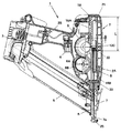
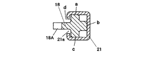
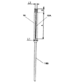
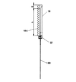
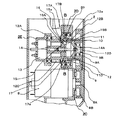
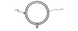
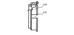
図1は本発明に係る電動式釘打機(携帯用打込機)の側断面図、図2は図1のA−A線拡大断面図、図3はプランジャとドライバブレードの正面図、図4は同プランジャとドライバブレードの破断側面図、図5は同電動式釘打機の駆動部(クラッチOFF状態)の平断面図、図6は図5のB−B線断面図、図7は同電動式釘打機の駆動部(クラッチON状態)の平断面図、図8は図7のC−C線断面図、図9はコイルスプリングの側面図、図10は同コイルスプリングの正面図、図11はフランジの破断側面図、図12はフランジに挿入されたコイルスプリングを示す破断側面図、図13は打込開始時の作用説明図、図14は打込終了時の作用説明図である。 1 is a side sectional view of an electric nail driver (portable driving machine) according to the present invention, FIG. 2 is an enlarged sectional view taken along line AA of FIG. 1, and FIG. 3 is a front view of a plunger and a driver blade. 4 is a cutaway side view of the plunger and the driver blade, FIG. 5 is a plan sectional view of the drive unit (clutch OFF state) of the electric nail driver, FIG. 6 is a sectional view taken along the line BB of FIG. FIG. 8 is a cross-sectional view taken along the line CC of FIG. 7, FIG. 9 is a side view of the coil spring, and FIG. 10 is a front view of the coil spring. 11 is a broken side view of the flange, FIG. 12 is a broken side view showing the coil spring inserted into the flange, FIG. 13 is an operation explanatory view at the start of driving, and FIG. 14 is an operational explanatory view at the end of driving. is there.
図1に示す電動式釘打機1において、2は外郭部材である樹脂製のハウジングであり、このハウジング2は、略円筒状の胴体部2Aと、該胴体部2Aに側面視で略T時状に連接されたハンドル部2Bとで構成されている。そして、このハウジング2のハンドル部2Bの末端部(胴体部2Aとは逆側の自由端部)には、電源としての不図示の電池を収納するための電池パック3が設けられている。又、ハウジング2のハンドル部2Bの胴体部2Aに近い部分にはトリガスイッチ4が設けられている。
In the
又、図1に示すように、ハウジング2の下端には射出部7が設けられており、その射出部7には、平坦な矩形ボックス状のマガジン5が側面視で胴体部2Aに対して斜めに取り付けられている。より具体的には、マガジン5は、その一端がハウジング2の胴体部2Aの先端に設けられた射出部7(図1の下端部)に取り付けられ、他端がハウジング2のハンドル部2Bの末端部の電池パック3近傍に取り付けられ、図1に示す状態で、ハウジング2の胴体部2Aの先端に設けられた射出部7からハンドル部2Bの末端部に向かって斜め上方に傾斜している。尚、図示しないが、マガジン5内には、階段状に連結された多数の釘6が収納されている。
Further, as shown in FIG. 1, an
次に、ハウジング2の内部構造を図1及び図5に基づいて説明する。
Next, the internal structure of the
ハウジング2の胴体部2A内には、駆動源としてのモータ8が横置き状態で収納されており、このモータ8から該モータ8の回転中心方向(図1の紙面垂直方向)に延びる出力軸(モータ軸)8Aの端部にはギヤ8Bが結着されている。
A
又、ハウジング2の胴体部2A内の前記モータ8の横には、図5に示すように、回転可能な従動軸12がモータ8の出力軸8Aと平行に配されており、この従動軸12にはピニオン12Cが形成されるとともに、フライホイール9が回転可能に支承され、このフライホイール9は、前記ギヤ8Bに噛合している。
Further, as shown in FIG. 5, a rotatable driven
又、図1に示すように、ハウジング2の胴体部2A内には、前記ピニオン12Cに噛合するプランジャ18がガイド手段である直線状のレール21に沿って図1の上下方向に往復直線移動可能に収納されており、このプランジャ18の先端(図1の下端)には、釘6を押し出すためのドライバブレード18Bがボルト22によって取り付けられている。尚、プランジャ18は、不図示のリターンスプリングによって初期位置に戻る方向(図1の上方)に付勢されている。又、本実施の形態では、ドライバブレード18Bをプランジャ18とは別体に構成し、これをボルト22によってプランジャ18に取り付ける構成を採用したが、ドライバブレード18Bをプランジャ18と一体に構成しても良い。
Further, as shown in FIG. 1, a
ここで、前記レール21は、前記プランジャ18の一部を覆って該プランジャ18の往復直線移動を案内するガイド手段を構成するものであって、図2に示すように、角パイプ状の中空部材で構成されている。そして、このレール21の一部(図2の左端面であって、前記ピニオン12Cに対向する面)には、プランジャ18の移動方向(図1の上下方向)に沿うスリット(開口部)21aが全長に亘って形成されている。従って、レール21は、プランジャ18のa面、b面及びc面を完全に覆い、d面はラック18Aを除く一部を覆う形状を有している(図2参照)。
Here, the
上述のように、本実施の形態では、レール21を角パイプ状の中空部材で構成するとともに、その一部にスリット21aを全長に亘って形成したため、該レール21を板状部材の折曲成形によって製造することができ、例えば金型を用いた金属板のプレス加工によってレール21を容易且つ安価に製造することができる。
As described above, in this embodiment, the
而して、図2に示すように、プランジャ18は、レール21に若干の隙間をもって嵌合することによって往復直線移動が該レール21によって案内されるが、その全長の50%以上の長さのレール21によって嵌合保持されていることが望ましい。そして、このプランジャ18の前記ピニオン12Cに対向する部分は、図2に示すように、レール21のスリット(開口部)21aから外部に突出しており、その突出部分には図1に示すようにラック18Aが形成され、このラック18Aには前記ピニオン12Cが噛合している。
Thus, as shown in FIG. 2, the
又、図1に示すように、ハウジング2の胴体部2A内には、図14示すように打込終了時にプランジャ18が激突するためのダンパ23が設けられている。ここで、ダンパ23は、ゴム等の弾性体でリング状に成形され、プランジャ18の激突による衝撃を吸収する機能を果たす。尚、図13び図14おいて、24はダンパ23を保持するためのダンパプレートである。
Further, as shown in FIG. 1, a
ところで、本実施の形態では、前記プランジャ18に形成されたラック18Aの歯幅を長さ方向に沿って2段階に変化させたことを特徴としている。具体的には、ラック18Aの打込開始時(図13参照)及び打込途中にピニオン12Cが噛合する部分Aの歯幅L1を図14示すように打込終了時にピニオン12Cが噛合する部分Bの歯幅L2よりも狭く(L1<L2(図3参照))設定したことを特徴とする。
By the way, the present embodiment is characterized in that the tooth width of the
ここで、ラック18AのB部分は、打込終了時にピニオン12Cから大きな衝撃反力を受ける部分であり、このB部分の歯幅L2は、大きな衝撃反力に耐え得るだけの強度が確保される値に設定される。これに対して、ラック18AのA部分は、打込開始時及び打込途中においてピニオン12Cが噛合する部分であって、このA部分に作用する力はB部分に作用する力よりも小さい。このため、ラック18AのA部分の歯幅L1としては、比較的小さな力に耐え得るだけの強度が確保されれば良く、従って、本実施の形態では、ラック18AのA部分の歯幅L1をB部分の歯幅L2よりも小さく(L1<L2)設定している。即ち、本実施の形態では、ラック18Aの歯幅を、その部分に作用する力の大きさに応じて設定している。尚、本実施の形態では、ラック18Aの歯幅を長さ方向に沿って2段階に変化させたが、ラック18Aの歯幅を長さ方向3段階以上に変化させても良い。又、図15(a),(b)に示すように、ラック18Aの歯幅を長さ方向に沿って連続的に変化させても良い。ここで、図15(a)はプランジャ18とドライバブレード18Bの正面図、図15(b)は同プランジャ18とドライバブレード18Bの破断側面図である。
Here, the B portion of the
ところで、前記フライホイール9と従動軸12との間には、これらの連結を選択的にON/OFFするためのクラッチ機構が設けられているが、以下、このクラッチ機構の構成を図5〜図12に基づいて説明する。
Incidentally, a clutch mechanism is provided between the flywheel 9 and the driven
図5に示すように、ハウジング2の壁2Dには、ベアリング17Aを介して従動軸12が回転可能に支持されている。この従動軸12は、略筒状に成形され、ベアリング12Aを介してハウジング2の壁2Eによっても回転可能に支持されている。このように従動軸12は2箇所で支持されているため、これに急激に力が加えられた状態でも安定して回転することができる。そして、従動軸12の外周のベアリング12Aとベアリング17Aの間の部分には前記ピニオン12Cが形成されている。尚、壁2Eは後述のソレノイド13も支持している。
As shown in FIG. 5, the driven
又、図5に示すように、従動軸12には略環状の従動軸支持部17が嵌着されており、この従動軸支持部17を介して従動軸12がベアリング17Aによって支持されている。従動軸支持部17には軸方向に延出する延出部17Bが形成されており、該従動軸支持部17が従動軸12に嵌合した状態で、延出部17Bと従動軸12との間には溝17aが形成されている。
As shown in FIG. 5, a substantially annular driven
そして、従動軸12と延出部17Bとの間の溝17aには、後述するフランジ11Dの一部が挿入されており、この挿入されている部分のフランジ11Dと対向する位置には、従動軸12の内外を貫通する3つの孔12aが穿設されており(図6参照)、各孔12a内にはボール16がそれぞれ径方向に移動可能に設けられている。従って、ボール16は、後述のソレノイド駆動部14の伸縮方向及び従動軸12の周方向への移動が規制され、従動軸12の径方向への移動のみが許容されている。
A part of a
又、従動軸12の一端側であって、且つ、壁2Eで囲まれた領域内にはソレノイド13が配置されている。このソレノイド13からはソレノイド駆動部14が従動軸12内の空間に向けて延出しており、ソレノイド13に通電されるとソレノイド駆動部14が伸長する。そして、従動軸12内の空間のソレノイド駆動部14が伸縮する方向においてソレノイド駆動部14の端部と従動軸12との間には、ソレノイド捩りバネ14Aが縮装されており、このソレノイド捩りバネ14Aはソレノイド駆動部14を縮む方向に付勢している。
Further, a
更に、ソレノイド駆動部14の端部には、略円柱状の付勢部15が設けられており、この付勢部15は、円柱形状の軸方向を回転軸として回転可能となっている。ここで、付勢部15の外周には、軸方向に延びる溝が形成されており、この溝には、第1付勢面となる斜面を有する押圧部15Aと受け部15Bが設けられている。押圧部15Aの斜面は、ソレノイド13側に近づくほど中心部から離れるように形成されている。尚、付勢部15の最外径は、従動軸12内の空間の内径よりも僅かに小さく設定されている。
Furthermore, a substantially columnar urging
そして、押圧部15Aと受け部15B及び従動軸12の内部空間の内周面との間には隙間15aが形成されており、この隙間15aにおける受け部15B表面から従動軸12の内部空間の内周面までの距離と従動軸12の孔12a付近の肉厚との和がボール16の直径と略等しくなるよう受け部15Bが形成されている。
A gap 15a is formed between the
ソレノイド駆動部14の移動量は、該ソレノイド駆動部14が最も縮んでいる状態(動力遮断位置)で受け部15B表面が孔12aと対向する位置にあり、ソレノイド駆動部14が最も伸長している状態(動力接続位置)で押圧部15Aが孔12aと対向する位置にあるように調整されている。従って、ボール16は、ソレノイド駆動部14が縮んでいる状態で受け部15Bの表面と当接しており、この状態ではボール16の一部が孔12aから従動軸12の外周面より突出することはない(図5及び図6参照)。
The amount of movement of the
又、ソレノイド駆動部14が伸長している状態では、ボール16は押圧部15Aと当接する(図8参照)。この状態では、従動軸12の外周面よりボール16の一部が突出している(図7及び図8参照)。尚、電動式釘打機1の本体の傾きによっては、ボール16が重力によって孔12aから突出することがあるが、ボール16は押圧部15Aにより支持されていないため、付勢力は殆ど無く、後述のフランジ11Dが付勢されることはない。
Further, in a state where the
更に、図5に示すように、従動軸12の他端側であって孔12aより端部側にはスプリング着座部12Bが形成されており、このスプリング着座部12Bの最端部であってギヤ8Bと先後端方向において並列する位置には支持軸12Dが設けられている。そして、この支持軸12Dには、ベアリング9Aを介してフライホイール9が回転可能に設けられている。
Further, as shown in FIG. 5, a
ここで、従動軸12は、ハウジング2の一部である壁2D,2Eに対して回転可能に支持されているため、該従動軸12の一部である支持軸12Dにベアリング9Aを介して回転可能に設けられたフライホイール9は、従動軸12に対して自由に回転可能であるとともに、ハウジング2に対して回転可能に支持された状態になっている。尚、支持軸12Dの端部には、ベアリング9Aの脱落防止のための止め輪9Bが取り付けられている。
Here, since the driven
又、フライホイール9の外周には歯部が設けられており、この歯部は前記ギヤ8Bに噛合しており、ギヤ8Bが時計方向に回転することによってフライホイール9は反時計方向に回転する。そして、フライホイール9の従動軸12と同軸な位置には駆動軸10が一体に形成されている。
Further, a tooth portion is provided on the outer periphery of the flywheel 9, and this tooth portion meshes with the
図9〜図12に示すように、コイルスプリング11の他端側11Bにはフランジ11Dが設けられている。このフランジ11Dは略環状の部材であり、その円周上の一部には切欠き11Eが形成されている。そして、このフランジ11Dとコイルスプリング11とは、フランジ11Dの内部にコイルスプリング11の他端側11Bが同軸的に挿入されるとともに、切欠き11C内にコイルスプリング11の他端側11Bの鋼線の先端である突出部11Cが挿入されている。従って、フランジ11Dとコイルスプリング11とは、コイルスプリング11の回転方向に関して一体に回転することができる。
As shown in FIGS. 9 to 12, a
図5に示すように、コイルスプリング11は、その一端側11Aが駆動軸10に固定されており、従動軸12のスプリング着座部12Bがコイルスプリング11内に挿入されている。又、ベアリング17Aに隣接してベアリング20が並設されており、コイルスプリング11の他端側11Bに設けられたフランジ11Dがベアリング20によって回転可能に支持されている。
As shown in FIG. 5, one
ここで、コイルスプリング11が自由状態にあるときには、該コイルスプリング11の内径は、フライホイール9の駆動軸10の最大外径と略等しく設定されている。又、従動軸12のスプリング着座部12Bの外径は駆動軸10の最大外径よりも小さいため、モータ8に通電されていない状態では、コイルスプリング11と従動軸12とは非連結状態にある。
Here, when the
図6に示すように、従動軸12に形成された孔12aに挿入されたボール16がスプリング着座部12Bの表面より突出していない場合には、フランジ11Dは溝17a内を自由に回転することができる。
As shown in FIG. 6, when the
次に、以上の構成を有する電動式釘打機1の作用について説明する。
Next, the operation of the
作業者がハウジング2のハンドル部2Bを把持してトリガスイッチ4を引いてこれをONすると、電池パック3内に収容された電池を電源としてモータ8が駆動される。すると、モータ8の出力軸8Aの回転は、ギヤ8Bからフライホイール9へと伝達され、該フライホイール9とその駆動軸10及びコイルスプリング11が所定の速度で回転駆動される。フライホイール9が回転駆動されると、その角速度が増し、該フライホイール9に回転エネルギーが蓄積される。このとき、コイルスプリング11は、図5に示すように、従動軸12に対して離間しているため、従動軸12が回転することはない。従って、この状態では、コイルスプリング11と従動軸12との間に摩耗は発生しない。
When the operator holds the handle portion 2B of the
而して、モータ8が回転を開始してから所定時間が経過し、フライホイール9に釘6を打ち込むのに必要な回転エネルギーが蓄積され、更にプッシュレバー25が被打込材Wに押し付けられている場合は、不図示の駆動回路が作動してソレノイド13に通電され、ソレノイド駆動部14がソレノイド捩りバネ14Aの付勢力に抗して伸長する。このとき、隙間15a内で、ボール16の付勢部15と接する面が受け部15B表面から押圧部15Aに変わる。押圧部15Aは斜面で構成されているとともに、ボール16はソレノイド駆動部14の伸縮方向には移動できないため、ソレノイド駆動部14が伸長することによって、ボール16は、押圧部15Aにより従動軸12の径方向外方に移動し、図7及び図8に示すように、従動軸12の表面より突出する。
Thus, a predetermined time elapses after the
図7及び図8に示すように、押圧部15Aによって3個のボール16がそれぞれスプリング着座部12Bの表面より突出した場合には、3個のボール16によってフランジ11Dが径方向外方へと押し広げられるため、ボール16とフランジ11Dとの間に摩擦力が生じることになる。その結果、図7に示すように、コイルスプリング11の内径が縮小され、コイルスプリング11と従動軸12と間の摩擦力が増加し、数十m秒後には、コイルスプリング11が従動軸12に締着されて従動軸12はコイルスプリング11及び駆動軸10と共に回転することになる。
As shown in FIGS. 7 and 8, when the three
又、付勢部15は、ソレノイド駆動部14に回転可能に設けられるとともに、従動軸12とボール16を介して連結されているため、従動軸12と共に回転する。ここで、従動軸12にはプランジャ18のラック18Aと噛合するピニオン12Cが形成されているため、従動軸12が回転すると、プランジャ18がハウジング2の先端側に移動する。
The urging
従動軸12が回転駆動される場合には、モータ8の出力のみならずフライホイール9に蓄積されていた回転エネルギーも従動軸12に伝達されるため、該従動軸12は、コイルスプリング11と連結された状態で急激に高速回転することになる。尚、ソレノイド13が駆動されると同時に、モータ8への電力供給を中止しても良い。
When the driven
ところで、打込開始時には、図13に示すように、プランジャ18とドライバブレード18Bは、不図示のリターンスプリングによって初期位置(図13の上限位置)にあり、ピニオン12Cはラック18AのA部分の端部(図13の下端部)に噛合している。
By the way, at the start of driving, as shown in FIG. 13, the
而して、前述のように従動軸12が急激に高速回転すると、該従動軸12と共にピニオン12Cも高速回転し、該ピニオン12Cが噛合するラック18Aが形成されたプランジャ18がハウジング2の先端側(図13の下方)に急激に移動し、プランジャ18の先端側に取り付けられたドライバブレード18Bも同方向に押し出され、射出部7内に収容された釘6にドライバブレード18Bの先端が衝突し、図14に示すように、この衝突力によって釘6が射出部7の射出口7aから押し出されて木材等の被打込材Wに打ち込まれる。
Thus, when the driven
ここで、打込終了時の状態を図14に示すが、打込終了時にはピニオン12Cはプランジャ18のラック18AのB部分(図14の上端部)に噛合し、このとき、プランジャ18は図示のようにダンパ23に激突し、その衝撃がダンパ23によって吸収され、プランジャ18のラック18AのB部分には大きな衝撃反力が作用する。
Here, FIG. 14 shows the state at the end of driving. At the end of driving, the
尚、電動式釘打機1の本体の傾きによっては、ボール16が重力によって孔12aから突出することがあるが、ボール16は押圧部15Aによって支持されていないため、付勢力は殆ど無く、フランジ11Dが付勢されることはない。
Depending on the inclination of the main body of the
そして、打込完了時にはソレイド13への通電も終了し、ソレイド駆動部14は、ソレノイド戻りバネ14Aの付勢力により縮む方向へと移動する。付勢部15も同様に移動するため、ボール16は受け部15B表面に着座する。これに従いコイルスプリン11の他端側11Bに設けられているフランジ11Dとボール16間の摩擦力が無くなる。すると、コイルスプリング11は、スプリング着座部12Bを締め付けていた箇所が緩んで打込動作が開始される前の内径に戻り、コイルスプリング11と従動軸12との連結が解除される。
When the driving is completed, the energization of the
釘6を被打込材Wに打ち込んだ後に従動軸12のコイルスプリング11と連結が解除されると、プランジャ18には、これを先端側へと付勢する力が作用しなくなるため、プランジャ18は、これに接続された不図示のリターンスプリングによって後端側(図1の上方)へと引き戻されて釘6を打ち込む前の状態に戻る。
When the connection with the
而して、以上の動作を繰り返すことによって、木材等の被打込材Wに釘6を連続的に打ち込むことができる。尚、プッシュレバー25を先に被打込材Wに押し付けた後に、トリガスイッチ4をON(引く)にしても良い。
Thus, by repeating the above operation, the
以上において、本実施の形態に係る電動式釘打機1においては、プランジャ18に形成されたラック18Aの打込開始時及び打込途中にピニオン12Cが噛合する部分(比較的小さな力が作用する部分)Aの歯幅L1を打込終了時にピニオン12Cが噛合する部分(大きな衝撃反力が作用する部分)Bの歯幅L2よりも狭く(L1<L2)設定したため、ラック18Aの歯幅をその部分に作用する力に応じた適切な値に設定することができ、ラック18Aの部分Aの歯幅L1を部分Bの歯幅L2よりも狭くした分だけプランジャ18の軽量化を図ることができる。因に、従来はラック18Aの歯幅は全長に亘って広い幅L2に設定されていた。
As described above, in the
而して、上述のようにプランジャ18が軽量化されると、該プランジャ18を速く加速することができるために打込時間を短縮することができ、打込時の摩擦によるエネルギー損失が小さく抑えてエネルギー効率を高めることができる。
Thus, when the
又、プランジャ18が軽いほど、該プランジャ18の加速時に釘打機本体が受ける反力が小さくなるため、打込時の反動が小さく抑えられて作業性が改善される。
Further, the lighter the
更に、プランジャ18が軽いと、該プランジャ18自体に蓄積される運動エネルギーが小さいため、打込時のプランジャ18の激突による衝撃を吸収するためのダンパ23の容積を小さくしてその小型化を図ることができる。
Further, if the
ここで、本発明の別形態を図16(a)〜(c)に示す。 Here, another embodiment of the present invention is shown in FIGS.
図16(a)は別形態に係るプランジャとドライバブレードの正面図、図16(b)は同プランジャとドライバブレードの破断側面図、図16(c)は同図(b)のD−D線断面図であり、ラックとピニオンの歯の噛合い状態を示す。尚、ラックとピニオンの歯の噛合い状態は実施の形態においても同様である。プランジャ18の両側面には図示のように溝状の減肉部18Cが長さ方向に沿って形成されている。このようにプランジャ18の両側部に減肉部18Cを形成すれば、該プランジャ18の更なる軽量化を図ることができ、軽量化に伴う打込時のエネルギー効率の向上と反動を小さく抑える効果を更に高めることができる。
16 (a) is a front view of a plunger and a driver blade according to another embodiment, FIG. 16 (b) is a cutaway side view of the plunger and the driver blade, and FIG. 16 (c) is a DD line in FIG. 16 (b). It is sectional drawing and shows the meshing state of the teeth of a rack and a pinion. The meshing state of the rack and pinion teeth is the same in the embodiment. Groove-shaped thinned portions 18C are formed on both side surfaces of the
尚、以上の実施の形態では、携帯用打込機一例として電動式釘打機について説明したが、締結具として釘以外のネジやステープラー等を打ち込むための他の任意の携帯用打込機に対しても本発明を適用することができる。 In the above embodiment, the electric nail driver has been described as an example of the portable driving machine. However, any other portable driving machine for driving a screw, stapler, or the like other than a nail as a fastener. The present invention can also be applied to this.
1 電動式釘打機(携帯用打込機)
2 ハウジング
2A 胴体部
2B ハンドル部
3 電池パック
4 トリガスイッチ
5 マガジン
6 釘
7 射出部
8 モータ
8A 出力軸(モータ軸)
8B ギヤ
9 フライホイール
10 駆動軸
11 コイルスプリング
12 従動軸
12C ピニオン
13 ソレノイド
14 ソレノイド駆動部
15 付勢部
16 ボール
17 従動軸支持部
18 プランジャ
18A ラック
18B ドライバブレード
18C 減肉部
20 ベアリング
21 レール(ガイド手段)
21a スリット
22 ボルト
23 ダンパ
24 ダンパプレート
25 プッシュレバー
W 被打込材(木材)
1 Electric nailing machine (portable driving machine)
2
8B gear 9
Claims (4)
前記ラックの歯幅を長さ方向に沿って変化させたことを特徴とする携帯用打込機。 A driver blade for driving a fastener, a plunger configured integrally or separately with the driver blade, a rack formed on the plunger, a pinion meshing with the rack, and a driving means for rotationally driving the pinion In a portable driving machine for driving a fastener by linearly moving the plunger and the driver blade by rotation of the pinion,
A portable driving machine characterized in that the tooth width of the rack is changed along the length direction.
Priority Applications (4)
| Application Number | Priority Date | Filing Date | Title |
|---|---|---|---|
| JP2006064286A JP2007237345A (en) | 2006-03-09 | 2006-03-09 | Portable hammering machine |
| DE102007010533A DE102007010533A1 (en) | 2006-03-09 | 2007-03-05 | Portable drive device |
| US11/683,574 US20070210134A1 (en) | 2006-03-09 | 2007-03-08 | Portable driver |
| CNB2007100797748A CN100513087C (en) | 2006-03-09 | 2007-03-09 | Portable driver |
Applications Claiming Priority (1)
| Application Number | Priority Date | Filing Date | Title |
|---|---|---|---|
| JP2006064286A JP2007237345A (en) | 2006-03-09 | 2006-03-09 | Portable hammering machine |
Publications (2)
| Publication Number | Publication Date |
|---|---|
| JP2007237345A true JP2007237345A (en) | 2007-09-20 |
| JP2007237345A5 JP2007237345A5 (en) | 2009-01-22 |
Family
ID=38477920
Family Applications (1)
| Application Number | Title | Priority Date | Filing Date |
|---|---|---|---|
| JP2006064286A Pending JP2007237345A (en) | 2006-03-09 | 2006-03-09 | Portable hammering machine |
Country Status (4)
| Country | Link |
|---|---|
| US (1) | US20070210134A1 (en) |
| JP (1) | JP2007237345A (en) |
| CN (1) | CN100513087C (en) |
| DE (1) | DE102007010533A1 (en) |
Cited By (4)
| Publication number | Priority date | Publication date | Assignee | Title |
|---|---|---|---|---|
| JP2015214001A (en) * | 2014-05-13 | 2015-12-03 | 株式会社マキタ | Driving tool |
| JP2018034258A (en) * | 2016-08-31 | 2018-03-08 | 日立工機株式会社 | Driving tool |
| JP2018130817A (en) * | 2017-02-17 | 2018-08-23 | 株式会社マキタ | Hammering tool |
| US10625407B2 (en) | 2014-05-30 | 2020-04-21 | Koki Holdings Co., Ltd. | Driving machine |
Families Citing this family (23)
| Publication number | Priority date | Publication date | Assignee | Title |
|---|---|---|---|---|
| JP2007237351A (en) * | 2006-03-09 | 2007-09-20 | Hitachi Koki Co Ltd | Portable hammering machine |
| JP2008012615A (en) * | 2006-07-05 | 2008-01-24 | Hitachi Koki Co Ltd | Driving machine |
| JP4986033B2 (en) * | 2007-03-26 | 2012-07-25 | 日立工機株式会社 | Driving machine |
| TW200906571A (en) * | 2007-08-03 | 2009-02-16 | De Poan Pneumatic Corp | Rocking type kinetic energy clutching device of electric nailing gun device |
| TW200906574A (en) * | 2007-08-03 | 2009-02-16 | De Poan Pneumatic Corp | Transmission device of nailing gun device |
| US20090095787A1 (en) * | 2007-10-12 | 2009-04-16 | Chia-Sheng Liang | Transmission Mechanism for Electric Nail Gun |
| FR2927225B1 (en) * | 2008-02-12 | 2010-04-23 | Modeste Schmitt | MACHINE FOR MAKING VEGETATION, IN PARTICULAR VINEYARDS |
| US8162073B2 (en) * | 2009-02-20 | 2012-04-24 | Robert Bosch Gmbh | Nailer with brushless DC motor |
| US8042717B2 (en) * | 2009-04-13 | 2011-10-25 | Stanley Fastening Systems, Lp | Fastener driving device with contact trip having an electrical actuator |
| DE102010030065A1 (en) | 2010-06-15 | 2011-12-15 | Hilti Aktiengesellschaft | driving- |
| DE102010030098A1 (en) | 2010-06-15 | 2011-12-15 | Hilti Aktiengesellschaft | driving- |
| DE102010030118A1 (en) | 2010-06-15 | 2011-12-15 | Hilti Aktiengesellschaft | driving- |
| CN102720825A (en) * | 2012-06-28 | 2012-10-10 | 三一重工股份有限公司 | Gear, transmission system and engineering machine |
| CN105818099B (en) * | 2016-05-26 | 2017-11-17 | 杭州科龙电器工具股份有限公司 | Use the electric nail gun of gas spring |
| EP3323561A1 (en) * | 2016-11-18 | 2018-05-23 | HILTI Aktiengesellschaft | Setting device and method for operating same |
| CN110757413B (en) * | 2018-07-26 | 2022-08-26 | 创科无线普通合伙 | Pneumatic tool |
| USD900575S1 (en) | 2018-09-26 | 2020-11-03 | Milwaukee Electric Tool Corporation | Powered fastener driver |
| CN217394880U (en) | 2019-06-14 | 2022-09-09 | 米沃奇电动工具公司 | Power fastener driver |
| US11951601B2 (en) | 2019-06-14 | 2024-04-09 | Milwaukee Electric Tool Corporation | Lifter mechanism for a powered fastener driver |
| US20220219301A1 (en) | 2019-06-14 | 2022-07-14 | Milwaukee Electric Tool Corporation | Lifter mechanism for a powered fastener driver |
| TW202134018A (en) * | 2020-03-04 | 2021-09-16 | 鑽全實業股份有限公司 | Electric nail gun with buffer mechanism |
| WO2021195188A1 (en) | 2020-03-25 | 2021-09-30 | Milwaukee Electric Tool Corporation | Powered fastener driver |
| JP7332522B2 (en) * | 2020-03-31 | 2023-08-23 | 株式会社マキタ | driving tool |
Citations (3)
| Publication number | Priority date | Publication date | Assignee | Title |
|---|---|---|---|---|
| JPS543678U (en) * | 1977-06-10 | 1979-01-11 | ||
| JPH09300238A (en) * | 1996-05-10 | 1997-11-25 | Hitachi Koki Co Ltd | Driver blade of driving machine |
| JP2006026858A (en) * | 2004-07-20 | 2006-02-02 | Max Co Ltd | Fastener driving machine |
Family Cites Families (10)
| Publication number | Priority date | Publication date | Assignee | Title |
|---|---|---|---|---|
| US2575455A (en) * | 1945-12-12 | 1951-11-20 | Bocjl Corp | Impact tool |
| US3589588A (en) * | 1969-07-14 | 1971-06-29 | George O Vasku | Impact tool |
| US4129240A (en) * | 1977-07-05 | 1978-12-12 | Duo-Fast Corporation | Electric nailer |
| US4215808A (en) * | 1978-12-22 | 1980-08-05 | Sollberger Roger W | Portable electric fastener driving apparatus |
| DE8704666U1 (en) * | 1986-08-02 | 1987-05-21 | Demba Metallwarenfabrik GmbH, 2072 Bargteheide | Electrically operated tacker |
| US4834278A (en) * | 1988-06-13 | 1989-05-30 | Lin Chung Cheng | Structure of dc motorized nailing machine |
| US5511715A (en) * | 1993-02-03 | 1996-04-30 | Sencorp | Flywheel-driven fastener driving tool and drive unit |
| US5388749A (en) * | 1993-05-13 | 1995-02-14 | Avery Dennison Corp. | Electric powered apparatus for dispensing individual plastic fasteners from fastener stock |
| US6669072B2 (en) * | 2000-12-22 | 2003-12-30 | Senco Products, Inc. | Flywheel operated nailer |
| GB2406070B (en) * | 2002-07-25 | 2005-06-29 | Yih Kai Entpr Co Ltd | Handy electric nailing gun |
-
2006
- 2006-03-09 JP JP2006064286A patent/JP2007237345A/en active Pending
-
2007
- 2007-03-05 DE DE102007010533A patent/DE102007010533A1/en not_active Withdrawn
- 2007-03-08 US US11/683,574 patent/US20070210134A1/en not_active Abandoned
- 2007-03-09 CN CNB2007100797748A patent/CN100513087C/en not_active Expired - Fee Related
Patent Citations (3)
| Publication number | Priority date | Publication date | Assignee | Title |
|---|---|---|---|---|
| JPS543678U (en) * | 1977-06-10 | 1979-01-11 | ||
| JPH09300238A (en) * | 1996-05-10 | 1997-11-25 | Hitachi Koki Co Ltd | Driver blade of driving machine |
| JP2006026858A (en) * | 2004-07-20 | 2006-02-02 | Max Co Ltd | Fastener driving machine |
Cited By (6)
| Publication number | Priority date | Publication date | Assignee | Title |
|---|---|---|---|---|
| JP2015214001A (en) * | 2014-05-13 | 2015-12-03 | 株式会社マキタ | Driving tool |
| US10625407B2 (en) | 2014-05-30 | 2020-04-21 | Koki Holdings Co., Ltd. | Driving machine |
| JP2018034258A (en) * | 2016-08-31 | 2018-03-08 | 日立工機株式会社 | Driving tool |
| JP2018130817A (en) * | 2017-02-17 | 2018-08-23 | 株式会社マキタ | Hammering tool |
| WO2018151081A1 (en) * | 2017-02-17 | 2018-08-23 | 株式会社マキタ | Hammering tool |
| CN110300640A (en) * | 2017-02-17 | 2019-10-01 | 株式会社牧田 | Driver |
Also Published As
| Publication number | Publication date |
|---|---|
| CN101032812A (en) | 2007-09-12 |
| CN100513087C (en) | 2009-07-15 |
| DE102007010533A1 (en) | 2007-10-18 |
| US20070210134A1 (en) | 2007-09-13 |
Similar Documents
| Publication | Publication Date | Title |
|---|---|---|
| JP2007237345A (en) | Portable hammering machine | |
| JP4688060B2 (en) | Driving machine | |
| JP2007237351A (en) | Portable hammering machine | |
| JP5424009B2 (en) | Fastener driving machine | |
| US10442066B2 (en) | Driver | |
| JP2008012615A (en) | Driving machine | |
| JP4771286B2 (en) | Electric nailer | |
| JP2022118835A (en) | driving tool | |
| JP6203675B2 (en) | Driving tool | |
| JP2009000756A (en) | Driver | |
| JP2007216339A (en) | Motor-driven nailing machine | |
| WO2018061389A1 (en) | Rotary impact tool | |
| JP2009172732A (en) | Impact rotary tool | |
| JP7465647B2 (en) | Hammer Drill | |
| JP2013022691A (en) | Impact rotary tool | |
| WO2018061388A1 (en) | Rotary impact tool | |
| JP4399864B2 (en) | Electric tool | |
| JP3982509B2 (en) | Portable tools | |
| JP7471798B2 (en) | Driving tools | |
| JP2007118135A (en) | Driving machine | |
| JP6719084B2 (en) | Rotary impact tool | |
| JP7137447B2 (en) | driving tool | |
| JP4056041B2 (en) | Electric tool | |
| JP6638856B2 (en) | Screw tightening tool | |
| JP6607502B2 (en) | Impact rotary tool |
Legal Events
| Date | Code | Title | Description |
|---|---|---|---|
| A521 | Written amendment |
Free format text: JAPANESE INTERMEDIATE CODE: A523 Effective date: 20081128 |
|
| A621 | Written request for application examination |
Free format text: JAPANESE INTERMEDIATE CODE: A621 Effective date: 20081128 |
|
| RD05 | Notification of revocation of power of attorney |
Free format text: JAPANESE INTERMEDIATE CODE: A7425 Effective date: 20090126 |
|
| A977 | Report on retrieval |
Free format text: JAPANESE INTERMEDIATE CODE: A971007 Effective date: 20100909 |
|
| A131 | Notification of reasons for refusal |
Free format text: JAPANESE INTERMEDIATE CODE: A131 Effective date: 20100921 |
|
| A02 | Decision of refusal |
Free format text: JAPANESE INTERMEDIATE CODE: A02 Effective date: 20110201 |
