JP2007227221A - Lithium/iron disulphide primary cell - Google Patents
Lithium/iron disulphide primary cell Download PDFInfo
- Publication number
- JP2007227221A JP2007227221A JP2006048280A JP2006048280A JP2007227221A JP 2007227221 A JP2007227221 A JP 2007227221A JP 2006048280 A JP2006048280 A JP 2006048280A JP 2006048280 A JP2006048280 A JP 2006048280A JP 2007227221 A JP2007227221 A JP 2007227221A
- Authority
- JP
- Japan
- Prior art keywords
- lithium
- positive electrode
- battery
- iron disulfide
- transition metal
- Prior art date
- Legal status (The legal status is an assumption and is not a legal conclusion. Google has not performed a legal analysis and makes no representation as to the accuracy of the status listed.)
- Granted
Links
Images
Classifications
-
- H—ELECTRICITY
- H01—ELECTRIC ELEMENTS
- H01M—PROCESSES OR MEANS, e.g. BATTERIES, FOR THE DIRECT CONVERSION OF CHEMICAL ENERGY INTO ELECTRICAL ENERGY
- H01M6/00—Primary cells; Manufacture thereof
- H01M6/14—Cells with non-aqueous electrolyte
- H01M6/16—Cells with non-aqueous electrolyte with organic electrolyte
-
- H—ELECTRICITY
- H01—ELECTRIC ELEMENTS
- H01M—PROCESSES OR MEANS, e.g. BATTERIES, FOR THE DIRECT CONVERSION OF CHEMICAL ENERGY INTO ELECTRICAL ENERGY
- H01M4/00—Electrodes
- H01M4/02—Electrodes composed of, or comprising, active material
- H01M4/36—Selection of substances as active materials, active masses, active liquids
- H01M4/58—Selection of substances as active materials, active masses, active liquids of inorganic compounds other than oxides or hydroxides, e.g. sulfides, selenides, tellurides, halogenides or LiCoFy; of polyanionic structures, e.g. phosphates, silicates or borates
- H01M4/581—Chalcogenides or intercalation compounds thereof
- H01M4/5815—Sulfides
-
- H—ELECTRICITY
- H01—ELECTRIC ELEMENTS
- H01M—PROCESSES OR MEANS, e.g. BATTERIES, FOR THE DIRECT CONVERSION OF CHEMICAL ENERGY INTO ELECTRICAL ENERGY
- H01M6/00—Primary cells; Manufacture thereof
- H01M6/14—Cells with non-aqueous electrolyte
- H01M6/16—Cells with non-aqueous electrolyte with organic electrolyte
- H01M6/162—Cells with non-aqueous electrolyte with organic electrolyte characterised by the electrolyte
- H01M6/168—Cells with non-aqueous electrolyte with organic electrolyte characterised by the electrolyte by additives
-
- H—ELECTRICITY
- H01—ELECTRIC ELEMENTS
- H01M—PROCESSES OR MEANS, e.g. BATTERIES, FOR THE DIRECT CONVERSION OF CHEMICAL ENERGY INTO ELECTRICAL ENERGY
- H01M6/00—Primary cells; Manufacture thereof
- H01M6/14—Cells with non-aqueous electrolyte
- H01M6/16—Cells with non-aqueous electrolyte with organic electrolyte
- H01M6/162—Cells with non-aqueous electrolyte with organic electrolyte characterised by the electrolyte
- H01M6/166—Cells with non-aqueous electrolyte with organic electrolyte characterised by the electrolyte by the solute
Abstract
Description
この発明は、二硫化鉄を正極活物質とする正極と、リチウムを負極活物質とする負極と、有機溶媒を用いた電解液とを備えるリチウム/二硫化鉄一次電池に関する。 The present invention relates to a lithium / iron disulfide primary battery including a positive electrode using iron disulfide as a positive electrode active material, a negative electrode using lithium as a negative electrode active material, and an electrolytic solution using an organic solvent.
リチウム/二硫化鉄一次電池は、正極活物質の二硫化鉄が約894mAh/g、負極活物質のリチウムが約3863mAh/gと、非常に高い理論容量を示す正・負極材料から構成されており、高容量かつ軽量、負荷特性、低温特性といった電池特性の面からも、極めて優れた電池である。 The lithium / iron disulfide primary battery is composed of positive and negative electrode materials that have a very high theoretical capacity of about 894 mAh / g for the positive electrode active material iron disulfide and about 3863 mAh / g for the negative electrode active material lithium. The battery is extremely excellent in terms of battery characteristics such as high capacity and light weight, load characteristics, and low temperature characteristics.
さらに、リチウム/二硫化鉄一次電池は、初期の開回路電圧(OCV)が1.7V〜1.8V、平均放電電圧が1.3V〜1.6V付近であり、他の1.5V級一次電池、例えば水溶液を電解液に用いるマンガン電池、アルカリマンガン電池、酸化銀電池、空気電池、ニッケル/亜鉛電池と互換性を有する点からもその実用価値は高い。 Furthermore, the lithium / iron disulfide primary battery has an initial open circuit voltage (OCV) of 1.7 V to 1.8 V, an average discharge voltage of 1.3 V to 1.6 V, and other 1.5 V class primarys. The practical value is also high in terms of compatibility with batteries, for example, manganese batteries, alkaline manganese batteries, silver oxide batteries, air batteries, and nickel / zinc batteries using an aqueous solution as an electrolyte.
しかしながら、この電池系は、製造直後に、開回路電圧が実用電圧よりも高い電位まで上昇してしまうという問題がある。そこで、製造後に予備放電を行うことによって、開回路電圧を実用電圧まで低下させる手法がとられるが、長期間保管している間に再び開回路電圧が上昇し、場合によっては2Vを超えるという特徴を有している。 However, this battery system has a problem that the open circuit voltage rises to a potential higher than the practical voltage immediately after manufacture. Therefore, a method of reducing the open circuit voltage to a practical voltage by performing preliminary discharge after manufacture is taken, but the open circuit voltage rises again during long-term storage, and in some cases exceeds 2 V. have.
開回路電圧が上昇した状態にあるリチウム/二硫化鉄一次電池を機器に使用した場合には、使用機器側の保護回路が作動してしまうために、電源が入らず使用不可能となる。つまり他の1.5V級一次電池との互換性が失われる問題が生じてしまう。 When a lithium / iron disulfide primary battery in which the open circuit voltage is increased is used in a device, the protection circuit on the device side is activated, so that the power is not turned on and the device cannot be used. That is, the problem that compatibility with other 1.5V class primary batteries is lost arises.
開回路電圧の上昇の一因としては、導電剤に吸着されている酸素の影響が考えられる。この影響を抑制するために、例えば特許文献1には、電解液中に添加したイソキサゾール誘導体、正極中に添加した還元剤によって、導電剤中の活性種を還元除去する方法が記載されている。
One possible cause of the increase in the open circuit voltage is the influence of oxygen adsorbed on the conductive agent. In order to suppress this influence, for example,
また、開回路電圧の上昇の他の原因としては、外部からの水分進入とそれに伴う電池構成成分との反応が影響と考えられる。この影響を抑制するため、例えば特許文献2には、進入水分を、電解液中に添加したフェノールまたはヒドロキノン誘導体と優先的に反応させる方法が記載されている。 Another cause of the increase in the open circuit voltage is considered to be the influence of moisture ingress from outside and the reaction between the battery constituent components accompanying it. In order to suppress this influence, for example, Patent Document 2 describes a method of preferentially reacting ingress water with a phenol or hydroquinone derivative added to an electrolytic solution.
しかしながら、特許文献1および特許文献2に記載の添加剤を使用する方法では、開回路電圧の上昇を抑制できるものであるが、放電特性の低下が懸念される。
However, in the method using the additive described in
したがって、この発明の目的は、放電特性の低下が少なく、且つ保存時における開回路電圧の上昇を抑制できる、リチウム/二硫化鉄一次電池を提供することにある。 Accordingly, an object of the present invention is to provide a lithium / iron disulfide primary battery that is less likely to be deteriorated in discharge characteristics and can suppress an increase in open circuit voltage during storage.
上述した課題を解決するために、この発明は、
二硫化鉄を正極活物質とする正極と、
リチウムを負極活物質とする負極と、
有機電解液とを備えたリチウム/二硫化鉄一次電池であって、
有機電解液は、遷移金属カチオンを含むものであること
を特徴とするリチウム/二硫化鉄一次電池である。
In order to solve the above-described problems, the present invention provides:
A positive electrode using iron disulfide as a positive electrode active material;
A negative electrode using lithium as a negative electrode active material;
A lithium / iron disulfide primary battery comprising an organic electrolyte,
The organic electrolyte is a lithium / iron disulfide primary battery characterized by containing a transition metal cation.
この発明では、有機電解液は、遷移金属カチオンを含むものであるので、放電特性の低下が少なく、且つ長期保存時の開回路電圧の上昇を抑制できる。Cuイオンを始めとするSnイオン、Znイオン、Niイオン、Agイオンの遷移金属カチオンは、Sと化合物を作りやすく、正極に取り込まれることで安定な無機被膜を形成しているものと考えられる。また、硫黄化合物を形成することで正極が異なる電位環境におかれることで、保存時の開回路電圧上昇の原因となる各種反応が、抑制されているものと考えられる。 In the present invention, since the organic electrolyte contains a transition metal cation, the discharge characteristics are hardly lowered and an increase in open circuit voltage during long-term storage can be suppressed. It is considered that transition metal cations such as Cu ions, Sn ions, Zn ions, Ni ions, and Ag ions easily form a compound with S and form a stable inorganic film by being incorporated into the positive electrode. Moreover, it is thought that various reactions that cause an increase in open circuit voltage during storage are suppressed by forming the sulfur compound to place the positive electrode in different potential environments.
この発明によれば、放電特性の低下が少なく、且つ保存時の開回路電圧の上昇を抑制できる。 According to the present invention, there is little deterioration in discharge characteristics, and an increase in open circuit voltage during storage can be suppressed.
以下、この発明の実施の形態について図面を参照して説明する。 Embodiments of the present invention will be described below with reference to the drawings.
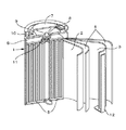
図1は、この発明の一実施形態によるリチウム/二硫化鉄一次電池を示す。図1に示す電池は、いわゆる円筒型と呼ばれるものであり、ほぼ中空円柱状の電池缶1の内部に、渦巻型電極体を有している。渦巻型電極体は、正極活物質を有する帯状の正極2と、負極活物質を有する帯状の負極3とが、イオン透過性を有するセパレータ4を介して多数回巻回されてなる。
FIG. 1 shows a lithium / iron disulfide primary battery according to an embodiment of the present invention. The battery shown in FIG. 1 is a so-called cylindrical type, and has a spiral electrode body inside a substantially hollow cylindrical battery can 1. The spiral electrode body is formed by winding a strip-shaped positive electrode 2 having a positive electrode active material and a strip-shaped
電池缶1は、例えばニッケルメッキが施された鉄により、構成されており、一端部が閉鎖され、他端部が開放されている。電池缶1の内部には、渦巻型電極体を挟み込むように、周面に対して垂直に一対の絶縁板5および絶縁板6がそれぞれ配置されている。
The battery can 1 is made of, for example, iron plated with nickel, and has one end closed and the other end open. Inside the battery can 1, a pair of
電池缶1の開放端部には、電池蓋7と、この電池蓋7の内側に設けられた安全弁8及び熱感抵抗素子(Positive Temperature Coefficient;PTC素子)9とが、封口ガスケット10を介してかしめられることにより取り付けられており、電池缶1の内部は、密閉されている。
At the open end of the battery can 1, a battery lid 7, a safety valve 8 and a heat sensitive resistance element (Positive Temperature Coefficient; PTC element) 9 provided inside the battery lid 7 are provided via a sealing
電池蓋7は、例えば電池缶1と同様の材料により構成されている。安全弁8は、熱感抵抗素子9を介して電池蓋7と電気的に接続されており、内部短絡又は外部からの加熱等により電池の内圧が一定以上となった場合に電池蓋7と渦巻型電極体との電気的接続を切断する、いわゆる電流遮断機構を備えている。 The battery lid 7 is made of, for example, the same material as the battery can 1. The safety valve 8 is electrically connected to the battery lid 7 via the heat sensitive resistance element 9, and when the internal pressure of the battery becomes a certain level or more due to internal short circuit or external heating, the safety valve 8 and the spiral lid A so-called current interrupting mechanism for disconnecting the electrical connection with the electrode body is provided.
熱感抵抗素子9は、温度が上昇すると抵抗値の増大により電流を制限し、大電流による異常な発熱を防止するものであり、例えば、チタン酸バリウム系半導体セラミックスにより構成されている。封口ガスケット10は、例えば絶縁材料により構成されており、表面には、例えばアスファルトが塗布されている。
When the temperature rises, the heat-sensitive resistance element 9 limits the current by increasing the resistance value and prevents abnormal heat generation due to a large current, and is made of, for example, barium titanate semiconductor ceramics. The sealing
渦巻型電極体の正極2には、アルミニウム等よりなる正極リード11が接続されており、負極3には、ニッケル等よりなる負極リード12が接続されている。正極リード11は、安全弁8に溶接されることにより電池蓋7と電気的に接続されている。負極リード12は、電池缶1に溶接され電気的に接続されている。
A
また、正極2と負極3との間のセパレータ4には、非水電解質として、例えば非水電解液が含浸されている。セパレータ4は、正極2と負極3との間に配されることにより、正極2と負極3の物理的接触を防ぐ機能を有する。さらに、セパレータ4は、非水電解液を吸収することにより、孔中に非水電解液を保持し、放電時にリチウムイオンが通過できるものである。
Further, the separator 4 between the positive electrode 2 and the
[正極2]
正極2は、帯状の形状を有する正極集電体と、この正極集電体の両面に形成された正極合剤層とからなる。正極集電体は、例えばアルミニウム(Al)箔、ニッケル(Ni)箔、ステンレス(SUS)箔等の金属箔である。
[Positive electrode 2]
The positive electrode 2 is composed of a positive electrode current collector having a strip shape and a positive electrode mixture layer formed on both surfaces of the positive electrode current collector. The positive electrode current collector is a metal foil such as an aluminum (Al) foil, a nickel (Ni) foil, a stainless steel (SUS) foil, or the like.
正極合剤層は、例えば、正極活物質である二硫化鉄(FeS2)と、導電剤と、結着剤とからなる。正極活物質である二硫化鉄は、主に自然界に存在する黄鉄鉱(pyrite)を粉砕したものが用いられるが、化学合成、例えば、塩化第一鉄(FeCl2)を硫化水素(H2S)中にて焼成して得られる二硫化鉄なども使用可能である。 The positive electrode mixture layer includes, for example, iron disulfide (FeS 2 ) that is a positive electrode active material, a conductive agent, and a binder. As the positive electrode active material, iron disulfide, which is obtained by pulverizing pyrite that exists mainly in nature, is used, but chemical synthesis, for example, ferrous chloride (FeCl 2 ) is converted to hydrogen sulfide (H 2 S). Iron disulfide obtained by firing inside can also be used.
導電剤としては、正極活物質に適量混合して導電性を付与できるものであれば特に制限はされず、例えば、グラファイト、カーボンブラックなどの炭素粉末を用いることができる。結着剤としては、公知の結着剤を用いることができ、例えばポリフッ化ビニル(PVF)、ポリフッ化ビニリデン(PVDF)、ポリテトラフルオロエチレンなどのフッ素系樹脂を用いることができる。 The conductive agent is not particularly limited as long as an appropriate amount can be mixed with the positive electrode active material to impart conductivity, and for example, carbon powder such as graphite and carbon black can be used. As the binder, a known binder can be used. For example, a fluorine resin such as polyvinyl fluoride (PVF), polyvinylidene fluoride (PVDF), polytetrafluoroethylene, or the like can be used.
[負極3]
負極3は、帯状の形状を有する金属箔からなる。この負極活物質でもある金属箔の材料としては、リチウム金属またはリチウムにアルミなどの合金元素を添加したリチウム合金などが挙げられる。
[Negative electrode 3]
The
[電解液]
電解液としては、リチウム塩を電解質として、これを有機溶媒に溶解させた電解液が用いられる。この電解液は、遷移金属カチオンを含有するものである。これにより、リチウム/二硫化鉄一次電池の長期保存時における開回路電圧の上昇を抑制できる。
[Electrolyte]
As the electrolytic solution, an electrolytic solution in which a lithium salt is used as an electrolyte and dissolved in an organic solvent is used. This electrolytic solution contains a transition metal cation. Thereby, the raise of the open circuit voltage at the time of long-term preservation | save of a lithium / iron disulfide primary battery can be suppressed.
遷移金属カチオンとしては、例えば、Cuイオンを始めとするSnイオン、Znイオン、Niイオン、Agイオンを用いることができる。遷移金属カチオンは、例えば、遷移金属カチオンと対をなすアニオン種とからなる塩の形で電解液中に添加することにより、電解液に含有させることができる。塩としては、例えば、トリフレート塩、過塩素酸塩、ハロゲン塩等を挙げることができる。塩のなかでより好ましいのは、トリフレートアニオンが特に電池特性に大きく影響を与えるものではない点から、トリフレート塩である。トリフレート塩は、一般式としては、下記一般式Iで表される。
(式I)
Men+(CF3SO3)n
(式I中、Men+は遷移金属カチオンを示す。nは遷移金属カチオンの価数を示す。)
As the transition metal cation, for example, Sn ions including Cu ions, Zn ions, Ni ions, and Ag ions can be used. The transition metal cation can be contained in the electrolytic solution, for example, by adding it to the electrolytic solution in the form of a salt composed of an anionic species paired with the transition metal cation. Examples of the salt include triflate salt, perchlorate salt, halogen salt and the like. Among these salts, triflate salts are more preferable because the triflate anion does not particularly affect the battery characteristics. The triflate salt is represented by the following general formula I as a general formula.
(Formula I)
Me n + (CF 3 SO 3 ) n
(In formula I, Me n + represents a transition metal cation. N represents the valence of the transition metal cation.)
電解液中の遷移金属カチオンの含有量は、開回路電圧の上昇を抑制する効果を十分に得ることができる点、放電性能の低下が少ない点から0.01mol/kg〜1.0mol/kgであることが好ましい。 The content of the transition metal cation in the electrolytic solution is 0.01 mol / kg to 1.0 mol / kg from the viewpoint that a sufficient effect of suppressing an increase in open circuit voltage can be obtained and the decrease in discharge performance is small. Preferably there is.
有機溶媒としては、例えば、プロピレンカーボネート、エチレンカーボネート、1,2−ジメトキシエタン、γ−ブチロラクトン、テトラヒドロフラン、2−メチルテトラヒドロフラン、1,3−ジオキソラン、スルホラン、アセトニトリル、ジメチルカーボネート、ジプロピルカーボネート等の、単独もしくは二種類以上の混合溶媒を用いることができる。 Examples of the organic solvent include propylene carbonate, ethylene carbonate, 1,2-dimethoxyethane, γ-butyrolactone, tetrahydrofuran, 2-methyltetrahydrofuran, 1,3-dioxolane, sulfolane, acetonitrile, dimethyl carbonate, dipropyl carbonate, and the like. A single or two or more kinds of mixed solvents can be used.
電解質には、LiClO4、LiPF6、LiBF4、LiCF3SO3、LiC4F9SO3、LiAs6、LiI、LiBr、Li(CF3SO2)2N、Li(C2F5SO2)(CF3SO2)N、Li(C2F5SO2)2N等が使用可能である。 The electrolytes include LiClO 4 , LiPF 6 , LiBF 4 , LiCF 3 SO 3 , LiC 4 F 9 SO 3 , LiAs 6 , LiI, LiBr, Li (CF 3 SO 2 ) 2 N, Li (C 2 F 5 SO 2 ) (CF 3 SO 2 ) N, Li (C 2 F 5 SO 2 ) 2 N, or the like can be used.
[セパレータ]
セパレータ4としては、例えば、ポリプロピレン、ポリエチレンといったポリオレフィン系の微多孔性フィルム等が使用可能である。
[Separator]
As the separator 4, for example, a polyolefin-based microporous film such as polypropylene or polyethylene can be used.
次に、この発明の一実施形態によるリチウム/二硫化鉄一次電池の製造方法について説明する。 Next, a method for manufacturing a lithium / iron disulfide primary battery according to an embodiment of the present invention will be described.
まず、例えば、正極活物質、結着剤および導電剤を混合して正極合剤を調製し、この正極合剤をN−メチル−2−ピロリドン(NMP)などの溶剤に分散してペースト状の正極合剤スラリーとする。この正極合剤スラリーを正極集電体上に塗布して乾燥させた後、ローラプレス機などにより圧縮成型して正極合剤層を形成する。これにより、正極2が作製される。 First, for example, a positive electrode active material, a binder, and a conductive agent are mixed to prepare a positive electrode mixture, and this positive electrode mixture is dispersed in a solvent such as N-methyl-2-pyrrolidone (NMP) to form a paste A positive electrode mixture slurry is obtained. The positive electrode mixture slurry is applied onto a positive electrode current collector and dried, and then compression molded by a roller press or the like to form a positive electrode mixture layer. Thereby, the positive electrode 2 is produced.
次に、上述のようにして得られた帯状の正極2と、帯状の形状を有する負極3と、帯状の形状を有するセパレータ4とを、例えば正極2、セパレータ4、負極3、セパレータ4の順に積層し、長手方向に多数回巻回して、渦巻型電極体を作製する。
Next, the strip-shaped positive electrode 2 obtained as described above, the
次に、底部に絶縁板5が予め挿入され、内側に例えばニッケルメッキが予め施された電池缶1に、渦巻型電極体を収納する。そして、渦巻型電極体の上面に絶縁板6を配設する。その後、負極3の集電をとるために、例えばニッケルからなる負極リード12の一端を負極3に取り付け、他端を電池缶1に溶接する。
Next, the spiral electrode body is accommodated in the battery can 1 in which the insulating plate 5 is inserted in advance at the bottom and nickel plating is applied in advance on the inside. Then, the insulating
これにより、電池缶1は負極3と導通をもつことになり、外部負極となる。また、正極2の集電をとるために、例えばアルミニウムからなる正極リード11の一端を正極2に取り付け、他端を安全弁8を介して電池蓋7と電気的に接続する。これにより、電池蓋7は正極2と導通をもつこととなり、外部正極となる。
As a result, the battery can 1 is electrically connected to the
そして、この電池缶1の中に、遷移金属カチオンを添加した電解液を注入した後に、アスファルトを塗布した封口ガスケット10を介して電池缶1をかしめる。これにより、電池蓋7が固定された円筒型のリチウム/二硫化鉄一次電池が作製される。
And after inject | pouring the electrolyte solution which added the transition metal cation into this battery can 1, the battery can 1 is caulked through the sealing
以下、実施例によりこの発明を具体的に説明するが、この発明はこれらの実施例に限定されるものではない。 EXAMPLES Hereinafter, the present invention will be specifically described with reference to examples, but the present invention is not limited to these examples.

表1は、実施例1〜実施例45および比較例1に関するものである。以下、表1を参照して、実施例1〜実施例45および比較例1について説明する。 Table 1 relates to Examples 1 to 45 and Comparative Example 1. Hereinafter, Example 1 to Example 45 and Comparative Example 1 will be described with reference to Table 1.
<実施例1>
まず、正極活物質としての二硫化鉄95重量%と、導電剤としての炭素粉末1.0重量%と、結着剤としてのポリフッ化ビニリデン4重量%とを混合し、溶剤であるN−メチル−2−ピロリドンに十分に分散させて正極合剤スラリーとした。
<Example 1>
First, 95% by weight of iron disulfide as a positive electrode active material, 1.0% by weight of carbon powder as a conductive agent, and 4% by weight of polyvinylidene fluoride as a binder are mixed, and N-methyl as a solvent is mixed. A positive electrode mixture slurry was obtained by sufficiently dispersing in 2-pyrrolidone.
次に、正極合剤スラリーを正極集電体の両面に塗布し、温度120℃で2時間乾燥させてN−メチル−2−ピロリドンを揮発させた後、一定圧力で圧縮成型して帯状の正極2を作製した。なお、正極集電体としては、厚さ20μmの帯状のアルミニウム箔を用いた。 Next, the positive electrode mixture slurry was applied to both sides of the positive electrode current collector, dried at a temperature of 120 ° C. for 2 hours to volatilize N-methyl-2-pyrrolidone, and then compression-molded at a constant pressure to form a belt-like positive electrode 2 was produced. As the positive electrode current collector, a band-shaped aluminum foil having a thickness of 20 μm was used.
次に、以上のようにして作製された帯状の正極2と、厚さ150μmの金属リチウム負極3とを、正極2、セパレータ4、負極3、セパレータ4の順に積層してから多数回巻回し、外径9mmの渦巻型電極体を作製した。
Next, the belt-like positive electrode 2 produced as described above and the lithium metal
以上のようにして得られた渦巻型電極体をニッケルメッキを施した鉄製電池缶1に収納した。そして、渦巻型電極体の上下両面に絶縁板5と絶縁板6を配設し、アルミニウム製の正極リード11を正極集電体から導出して電池蓋7に、ニッケル製の負極リード12を負極集電体から導出して電池缶1に溶接した。
The spiral electrode body obtained as described above was stored in a nickel-plated iron battery can 1. The insulating plate 5 and the insulating
次に、1、3−ジオキシラン(DOL)と、1、2−ジメトキシエタン(DME)が体積比で2:1の混合溶媒に対して、ヨウ化リチウム(LiI)1.0mol/kgおよび0.005mol/kgの遷移金属カチオン(Cuイオン)をトリフレート塩の形で添加し、溶解させて調整した電解液を電池缶1に注入した。なお、金属トリフレート塩の添加量は、ICPによって電解液中の全溶媒に対する濃度mol/kgで規定される。 Next, with respect to a mixed solvent of 1,3-dioxirane (DOL) and 1,2-dimethoxyethane (DME) in a volume ratio of 2: 1, lithium iodide (LiI) 1.0 mol / kg and 0.1. An electrolyte solution prepared by adding 005 mol / kg transition metal cation (Cu ion) in the form of a triflate salt and dissolving it was injected into the battery can 1. In addition, the addition amount of a metal triflate salt is prescribed | regulated by ICP by the density | concentration mol / kg with respect to all the solvents in electrolyte solution.
次に、アスファルトが表面に塗布された絶縁封口ガスケット10を介して電池缶1をかしめることにより、電流遮断機構を有する安全弁8、熱感抵抗素子9および電池蓋7を固定して電池内の気密性を保持させた。以上により、直径約10mm、高さ約44mmの円筒型のリチウム/二硫化鉄一次電池を作製した。
Next, the battery can 1 is caulked through an insulating
<実施例2〜実施例9>
表1に示す量のCuイオンをトリフレート塩の形で添加した以外は、実施例1と同様にして、実施例2〜実施例9のリチウム/二硫化鉄一次電池を作製した。
<Example 2 to Example 9>
Lithium / iron disulfide primary batteries of Examples 2 to 9 were produced in the same manner as in Example 1 except that the amount of Cu ions shown in Table 1 was added in the form of a triflate salt.
<実施例10〜実施例18>
表1に示す量のSnイオンをトリフレート塩の形で添加した以外は、実施例1と同様にして、実施例10〜実施例18のリチウム/二硫化鉄一次電池を作製した。
<Example 10 to Example 18>
Lithium / iron disulfide primary batteries of Examples 10 to 18 were fabricated in the same manner as in Example 1 except that the amount of Sn ions shown in Table 1 was added in the form of a triflate salt.
<実施例19〜実施例27>
表1に示す量のZnイオンをトリフレート塩の形で添加した以外は、実施例1と同様にして、実施例19〜実施例27のリチウム/二硫化鉄一次電池を作製した。
<Example 19 to Example 27>
Lithium / iron disulfide primary batteries of Examples 19 to 27 were fabricated in the same manner as in Example 1 except that the amount of Zn ions shown in Table 1 was added in the form of a triflate salt.
<実施例28〜実施例36>
表1に示す量のNiイオンをトリフレート塩の形で添加した以外は、実施例1と同様にして、実施例28〜実施例36のリチウム/二硫化鉄一次電池を作製した。
<Example 28 to Example 36>
Lithium / iron disulfide primary batteries of Examples 28 to 36 were fabricated in the same manner as in Example 1 except that the amount of Ni ions shown in Table 1 was added in the form of a triflate salt.
<実施例37〜実施例45>
表1に示す量のAgイオンをトリフレート塩の形で添加した以外は、実施例1と同様にして、実施例37〜実施例45のリチウム/二硫化鉄一次電池を作製した。
<Example 37 to Example 45>
Lithium / iron disulfide primary batteries of Examples 37 to 45 were produced in the same manner as in Example 1 except that the amount of Ag ions shown in Table 1 was added in the form of a triflate salt.
<比較例1>
遷移金属カチオンを添加しなかったこと以外は、実施例1と同様にして、比較例1のリチウム/二硫化鉄一次電池を作製した。
<Comparative Example 1>
A lithium / iron disulfide primary battery of Comparative Example 1 was produced in the same manner as in Example 1 except that the transition metal cation was not added.
評価
作製した実施例1〜実施例45および比較例1のリチウム/二硫化鉄一電池を予備放電により電池容量の10%程度を放電させた後、室温(20℃)で1000時間保存し、この保存後の電池の開回路電圧を測定した。測定結果を表1に示す。
The lithium / iron disulfide mono-cells of Examples 1 to 45 and Comparative Example 1 that were prepared for evaluation were predischarged to discharge about 10% of the battery capacity, and then stored at room temperature (20 ° C.) for 1000 hours. The open circuit voltage of the battery after storage was measured. The measurement results are shown in Table 1.
表1に示すように、遷移金属カチオンを用いることで開回路電圧上昇が大幅に抑制できることがわかる。ただし、その効果は、1.0mol/kgで飽和した。 As shown in Table 1, it can be seen that an increase in open circuit voltage can be significantly suppressed by using a transition metal cation. However, the effect was saturated at 1.0 mol / kg.
また、表1に、実施例1〜実施例45のリチウム/二硫化鉄一次電池の10Ω放電0.9V終止の放電時間比(比較例1を1.00として算出)を示す。表1に示すように、添加量が1.0mol/kgを超えると放電性能の低下が顕著である。よって、添加量は1mol/kg以下が好ましい。 Table 1 shows the discharge time ratio of the lithium / iron disulfide primary batteries of Examples 1 to 45 at the end of 10Ω discharge 0.9V (calculated assuming Comparative Example 1 as 1.00). As shown in Table 1, when the addition amount exceeds 1.0 mol / kg, the discharge performance is significantly reduced. Therefore, the addition amount is preferably 1 mol / kg or less.
さらに、1,3−ジオキソラン(DOL)に加え、その他溶媒プロピレンカーボネート(PC)、エチレンカーボネート(EC)と、LiCF3SO3やLiClO4、LiPF6、Li(CF3SO3)2Nとの組み合わせに対する遷移金属の追加添加(0.5mol/kg)を検討するため、実施例46〜実施例80および比較例2〜比較例8のリチウム/二硫化鉄一次電池を作製した。下記表2は、実施例46〜実施例80および比較例2〜比較例8に関するものである。以下、表2を参照しながら実施例46〜実施例80および比較例2〜比較例8について説明する。 Furthermore, in addition to 1,3-dioxolane (DOL), other solvents propylene carbonate (PC), ethylene carbonate (EC), and LiCF 3 SO 3 , LiClO 4 , LiPF 6 , Li (CF 3 SO 3 ) 2 N Lithium / iron disulfide primary batteries of Example 46 to Example 80 and Comparative Example 2 to Comparative Example 8 were fabricated in order to study additional addition of transition metal to the combination (0.5 mol / kg). Table 2 below relates to Examples 46 to 80 and Comparative Examples 2 to 8. Hereinafter, Examples 46 to 80 and Comparative Examples 2 to 8 will be described with reference to Table 2.
<実施例46〜実施例50>
ヨウ化リチウム(LiI)の代わりに、LiCF3SO3を用いた。表2に示す遷移金属カチオンをトリフレート塩の形で表2に示す量添加した。この他は、実施例1と同様にして、実施例46〜実施例50のリチウム/二硫化鉄一次電池を作製した。
<Example 46 to Example 50>
LiCF 3 SO 3 was used instead of lithium iodide (LiI). The transition metal cation shown in Table 2 was added in the form shown in Table 2 in the form of a triflate salt. Other than this, the lithium / iron disulfide primary batteries of Examples 46 to 50 were fabricated in the same manner as Example 1.
<比較例2>
遷移金属カチオンを添加しなかった以外は、実施例46〜実施例50と同様にして、比較例2のリチウム/二硫化鉄一次電池を作製した。
<Comparative example 2>
A lithium / iron disulfide primary battery of Comparative Example 2 was produced in the same manner as in Examples 46 to 50 except that the transition metal cation was not added.
<実施例51〜実施例55>
ヨウ化リチウム(LiI)の代わりに、LiClO4を用いた。表2に示す遷移金属カチオンをトリフレート塩の形で表2に示す量添加した。この他は、実施例1と同様にして、実施例51〜実施例55のリチウム/二硫化鉄一次電池を作製した。
<Example 51 to Example 55>
LiClO 4 was used instead of lithium iodide (LiI). The transition metal cation shown in Table 2 was added in the form shown in Table 2 in the form of a triflate salt. Other than this, in the same manner as in Example 1, lithium / iron disulfide primary batteries of Examples 51 to 55 were produced.
<比較例3>
遷移金属カチオンを添加しなかった以外は、実施例51〜実施例55と同様にして、比較例3のリチウム/二硫化鉄一次電池を作製した。
<Comparative Example 3>
A lithium / iron disulfide primary battery of Comparative Example 3 was produced in the same manner as in Examples 51 to 55 except that the transition metal cation was not added.
<実施例56〜実施例60>
ヨウ化リチウム(LiI)の代わりに、LiPF6を用いた。表2に示す遷移金属カチオンをトリフレート塩の形で表2に示す量添加した。この他は、実施例1と同様にして、実施例56〜実施例60のリチウム/二硫化鉄一次電池を作製した。
<Example 56 to Example 60>
LiPF 6 was used instead of lithium iodide (LiI). The transition metal cation shown in Table 2 was added in the form shown in Table 2 in the form of a triflate salt. Other than this, the lithium / iron disulfide primary batteries of Examples 56 to 60 were fabricated in the same manner as in Example 1.
<比較例4>
遷移金属カチオンを添加しなかった以外は、実施例56〜実施例60と同様にして、比較例4のリチウム/二硫化鉄一次電池を作製した。
<Comparative example 4>
A lithium / iron disulfide primary battery of Comparative Example 4 was produced in the same manner as in Example 56 to Example 60 except that the transition metal cation was not added.
<実施例61〜実施例65>
ヨウ化リチウム(LiI)の代わりに、Li(CF3SO3)2Nを用いた。表2に示す遷移金属カチオンをトリフレート塩の形で表2に示す量添加した。この他は、実施例1と同様にして、実施例61〜実施例65のリチウム/二硫化鉄一次電池を作製した。
<Example 61 to Example 65>
Li (CF 3 SO 3 ) 2 N was used instead of lithium iodide (LiI). The transition metal cation shown in Table 2 was added in the form shown in Table 2 in the form of a triflate salt. Other than this, the lithium / iron disulfide primary batteries of Examples 61 to 65 were produced in the same manner as Example 1.
<比較例5>
遷移金属カチオンを添加しなかった以外は、実施例61〜実施例65と同様にして、比較例5のリチウム/二硫化鉄一次電池を作製した。
<Comparative Example 5>
A lithium / iron disulfide primary battery of Comparative Example 5 was produced in the same manner as in Examples 61 to 65 except that the transition metal cation was not added.
<実施例66〜実施例70>
ヨウ化リチウム(LiI)の代わりに、LiCF3SO3を用いた。1,3−ジオキソラン(DOL)の代わりに、プロピレンカーボネート(PC)を用いた。表2に示す遷移金属カチオンをトリフレート塩の形で表2に示す量添加した。この他は、実施例1と同様にして、実施例66〜実施例70のリチウム/二硫化鉄一次電池を作製した。
<Example 66 to Example 70>
LiCF 3 SO 3 was used instead of lithium iodide (LiI). Propylene carbonate (PC) was used in place of 1,3-dioxolane (DOL). The transition metal cation shown in Table 2 was added in the form shown in Table 2 in the form of a triflate salt. Other than this, the lithium / iron disulfide primary batteries of Examples 66 to 70 were fabricated in the same manner as Example 1.
<比較例6>
遷移金属カチオンを添加しなかった以外は、実施例66〜実施例70と同様にして、比較例6のリチウム/二硫化鉄一次電池を作製した。
<Comparative Example 6>
A lithium / iron disulfide primary battery of Comparative Example 6 was produced in the same manner as in Example 66 to Example 70 except that the transition metal cation was not added.
<実施例71〜実施例75>
ヨウ化リチウム(LiI)の代わりに、LiClO4を用いた。1,3−ジオキソラン(DOL)の代わりに、プロピレンカーボネート(PC)を用いた。表2に示す遷移金属カチオンをトリフレート塩の形で表2に示す量添加した。この他は、実施例1と同様にして、実施例71〜実施例75のリチウム/二硫化鉄一次電池を作製した。
<Examples 71 to 75>
LiClO 4 was used instead of lithium iodide (LiI). Propylene carbonate (PC) was used in place of 1,3-dioxolane (DOL). The transition metal cation shown in Table 2 was added in the form shown in Table 2 in the form of a triflate salt. Other than this, in the same manner as in Example 1, lithium / iron disulfide primary batteries of Examples 71 to 75 were produced.
<比較例7>
遷移金属カチオンを添加しなかった以外は、実施例71〜実施例75と同様にして、比較例7のリチウム/二硫化鉄一次電池を作製した。
<Comparative Example 7>
A lithium / iron disulfide primary battery of Comparative Example 7 was produced in the same manner as in Examples 71 to 75 except that the transition metal cation was not added.
<実施例76〜実施例80>
ヨウ化リチウム(LiI)の代わりに、LiPF6を用いた。1,3−ジオキソラン(DOL)の代わりに、エチレンカーボネート(EC)を用いた。表2に示す遷移金属カチオンをトリフレート塩の形で表2に示す量添加した。この他は、実施例1と同様にして、実施例76〜実施例80のリチウム/二硫化鉄一次電池を作製した。
<Example 76 to Example 80>
LiPF 6 was used instead of lithium iodide (LiI). Instead of 1,3-dioxolane (DOL), ethylene carbonate (EC) was used. The transition metal cation shown in Table 2 was added in the form shown in Table 2 in the form of a triflate salt. Other than this, the lithium / iron disulfide primary batteries of Examples 76 to 80 were manufactured in the same manner as Example 1.
<比較例8>
遷移金属カチオンを添加しなかった以外は、実施例76〜実施例80と同様にして、比較例8のリチウム/二硫化鉄一次電池を作製した。
<Comparative Example 8>
A lithium / iron disulfide primary battery of Comparative Example 8 was produced in the same manner as in Examples 76 to 80 except that the transition metal cation was not added.
評価
作製した実施例46〜実施例80および比較例2〜比較例8のリチウム/二硫化鉄一電池を予備放電により電池容量の10%程度を放電させた後、室温(20℃)で1000時間保存し、この保存後の電池の開回路電圧を測定した。測定結果を表2に示す。
The lithium / iron disulfide single batteries of Example 46 to Example 80 and Comparative Examples 2 to 8 that were prepared for evaluation were predischarged to discharge about 10% of the battery capacity, and then 1000 hours at room temperature (20 ° C.). The battery was stored, and the open circuit voltage of the battery after storage was measured. The measurement results are shown in Table 2.
表2に示すように、LiCF3SO3やLiClO4、LiPF6、Li(CF3SO3)2Nを使用した場合および他溶媒との組み合わせにおいても、DOL−LiI系と同様、遷移金属カチオンを添加することで開回路電圧の上昇が大幅に抑制されることがわかる。 As shown in Table 2, when using LiCF 3 SO 3 , LiClO 4 , LiPF 6 , Li (CF 3 SO 3 ) 2 N and in combination with other solvents, the transition metal cation is similar to the DOL-LiI system. It can be seen that the increase in open circuit voltage is significantly suppressed by adding.
この発明は、上述したこの発明の実施形態に限定されるものでは無く、この発明の要旨を逸脱しない範囲内で様々な変形や応用が可能である。 The present invention is not limited to the above-described embodiments of the present invention, and various modifications and applications are possible without departing from the spirit of the present invention.
例えば、実施例では、トリフレート塩の形での金属イオン添加を検討したが、金属イオンと対をなすアニオン種はこれに限定されるものではない。 For example, in the Examples, addition of a metal ion in the form of a triflate salt was examined, but the anion species paired with the metal ion is not limited thereto.
また、実施例には、単4形のリチウム/二硫化鉄一次電池を用いたが、この発明は、正極活物質として、酸化二銅、硫化鉄、鉄複合酸化物、三酸化ビスマス等を用い、負極としては、リチウムに加え、ナトリウム等のアルカリ金属やそれらの金属を用いた場合も適用可能である。また、電池形状も筒型に加えボタン型、コイン型、角型などにも適用可能である。 Moreover, although the AAA lithium / iron disulfide primary battery was used in the examples, this invention uses dicopper oxide, iron sulfide, iron composite oxide, bismuth trioxide, etc. as the positive electrode active material. As the negative electrode, in addition to lithium, alkali metals such as sodium and those metals are also applicable. Further, the battery shape is applicable to a button type, a coin type, a square type, etc. in addition to a cylindrical type.
1・・・電池缶
2・・・正極
3・・・負極
4・・・セパレータ
5・・・絶縁板
6・・・絶縁板
7・・・電池蓋
8・・・安全弁
9・・・熱感抵抗素子
10・・・封口ガスケット
11・・・正極リード
12・・・負極リード
DESCRIPTION OF
Claims (4)
リチウムを負極活物質とする負極と、
有機電解液とを備えたリチウム/二硫化鉄一次電池であって、
上記有機電解液は、遷移金属カチオンを含むものであること
を特徴とするリチウム/二硫化鉄一次電池。 A positive electrode using iron disulfide as a positive electrode active material;
A negative electrode using lithium as a negative electrode active material;
A lithium / iron disulfide primary battery comprising an organic electrolyte,
The lithium / iron disulfide primary battery is characterized in that the organic electrolyte contains a transition metal cation.
上記遷移金属カチオンは、Cuイオン、Snイオン、Znイオン、Niイオン、Agイオンよりなる群から選ばれたものであること
を特徴とするリチウム/二硫化鉄一次電池。 In claim 1,
The lithium / iron disulfide primary battery, wherein the transition metal cation is selected from the group consisting of Cu ion, Sn ion, Zn ion, Ni ion, and Ag ion.
上記遷移金属カチオンは、上記有機電解液溶媒において0.01mol/kg〜1.0mol/kgであること
を特徴とするリチウム/二硫化鉄一次電池。 In claim 1,
The lithium / iron disulfide primary battery, wherein the transition metal cation is 0.01 mol / kg to 1.0 mol / kg in the organic electrolyte solvent.
上記有機電解液は、上記遷移金属カチオンを下記一般式Iで表された塩の形で含むものであること
を特徴とするリチウム/二硫化鉄一次電池。
(式I)
Men+(CF3SO3)n
(式I中、Men+は遷移金属カチオンを示す。nは遷移金属カチオンの価数を示す。) In claim 1,
The said organic electrolyte solution contains the said transition metal cation in the form of the salt represented with the following general formula I, The lithium / iron disulfide primary battery characterized by the above-mentioned.
(Formula I)
Me n + (CF 3 SO 3 ) n
(In formula I, Me n + represents a transition metal cation. N represents the valence of the transition metal cation.)
Priority Applications (2)
| Application Number | Priority Date | Filing Date | Title |
|---|---|---|---|
| JP2006048280A JP4539584B2 (en) | 2006-02-24 | 2006-02-24 | Lithium / iron disulfide primary battery |
| US11/678,382 US20070202409A1 (en) | 2006-02-24 | 2007-02-23 | Lithium/iron disulfide primary cell |
Applications Claiming Priority (1)
| Application Number | Priority Date | Filing Date | Title |
|---|---|---|---|
| JP2006048280A JP4539584B2 (en) | 2006-02-24 | 2006-02-24 | Lithium / iron disulfide primary battery |
Publications (2)
| Publication Number | Publication Date |
|---|---|
| JP2007227221A true JP2007227221A (en) | 2007-09-06 |
| JP4539584B2 JP4539584B2 (en) | 2010-09-08 |
Family
ID=38444399
Family Applications (1)
| Application Number | Title | Priority Date | Filing Date |
|---|---|---|---|
| JP2006048280A Expired - Fee Related JP4539584B2 (en) | 2006-02-24 | 2006-02-24 | Lithium / iron disulfide primary battery |
Country Status (2)
| Country | Link |
|---|---|
| US (1) | US20070202409A1 (en) |
| JP (1) | JP4539584B2 (en) |
Cited By (2)
| Publication number | Priority date | Publication date | Assignee | Title |
|---|---|---|---|---|
| JP2012514839A (en) * | 2009-01-20 | 2012-06-28 | ザ ジレット カンパニー | Lithium battery with iron disulfide cathode and improved electrolyte |
| JP2012517668A (en) * | 2009-02-12 | 2012-08-02 | ザ ジレット カンパニー | Lithium battery with iron disulfide cathode |
Families Citing this family (17)
| Publication number | Priority date | Publication date | Assignee | Title |
|---|---|---|---|---|
| CN102187494B (en) * | 2007-10-19 | 2016-01-27 | 永备电池有限公司 | lithium-iron disulfide cell design |
| US8617743B2 (en) | 2007-12-05 | 2013-12-31 | The Gillette Company | Anode balanced lithium-iron disulfide primary cell |
| WO2009082862A1 (en) * | 2008-01-03 | 2009-07-09 | Huizhou City Desay Lithium Battery S & T Co. Ltd | High energy battery and the manufacture method thereof |
| US8465860B2 (en) * | 2008-01-23 | 2013-06-18 | The Gillette Company | Lithium cell |
| US8273483B2 (en) * | 2008-02-14 | 2012-09-25 | The Gillette Company | Lithium cell |
| US20090214950A1 (en) * | 2008-02-22 | 2009-08-27 | Bowden William L | Lithium cell |
| US8076028B2 (en) * | 2008-04-16 | 2011-12-13 | The Gillette Company | Lithium cell with cathode including iron disulfide and iron sulfide |
| US8859145B2 (en) * | 2008-05-23 | 2014-10-14 | The Gillette Company | Method of preparing cathode containing iron disulfide for a lithium cell |
| US20090317725A1 (en) * | 2008-06-23 | 2009-12-24 | Zhiping Jiang | Lithium cell with cathode containing iron disulfide |
| US8153296B2 (en) * | 2008-08-27 | 2012-04-10 | The Gillette Company | Lithium cell with cathode containing metal doped iron sulfide |
| US8460826B2 (en) * | 2009-06-08 | 2013-06-11 | Eveready Battery Companym Inc. | Lithium-iron disulfide cell design |
| US8048562B2 (en) | 2009-03-27 | 2011-11-01 | The Gillette Company | Lithium cell with improved iron disulfide cathode |
| CA2770360C (en) * | 2009-08-27 | 2018-03-06 | Eveready Battery Company, Inc. | Lithium-iron disulfide cathode formulation having high pyrite content and low conductive additives |
| US20110143218A1 (en) * | 2009-12-14 | 2011-06-16 | Issaev Nikolai N | Battery |
| US20110240108A1 (en) * | 2010-04-02 | 2011-10-06 | Matt Law | Method To Synthesize Colloidal Iron Pyrite (FeS2) Nanocrystals And Fabricate Iron Pyrite Thin Film Solar Cells |
| US20150135522A1 (en) * | 2012-08-09 | 2015-05-21 | Sanyo Electric Co., Ltd. | Method for producing battery pack |
| EP3258521B1 (en) * | 2016-06-14 | 2020-11-04 | VARTA Microbattery GmbH | Lithium primary cell with dme-free electrolytes |
Citations (10)
| Publication number | Priority date | Publication date | Assignee | Title |
|---|---|---|---|---|
| JPS5996667A (en) * | 1982-11-25 | 1984-06-04 | Nippon Telegr & Teleph Corp <Ntt> | Electrolyte for lithium battery |
| JPS61218070A (en) * | 1985-03-22 | 1986-09-27 | Sanyo Electric Co Ltd | Nonaqueous electrolyte battery |
| JPS61218071A (en) * | 1985-03-22 | 1986-09-27 | Sanyo Electric Co Ltd | Nonaqueous electrolyte battery |
| JPS6229071A (en) * | 1985-07-31 | 1987-02-07 | Sony Ebaredei Kk | Organic electrolyte battery |
| JPS62145651A (en) * | 1985-12-18 | 1987-06-29 | Matsushita Electric Ind Co Ltd | Organic electrolytic solution battery |
| JPS63257183A (en) * | 1987-04-13 | 1988-10-25 | Sanyo Electric Co Ltd | Nonaqueous electrolytic solution battery |
| JPH07105958A (en) * | 1993-10-01 | 1995-04-21 | Sony Corp | Primary battery |
| JPH11507761A (en) * | 1995-06-07 | 1999-07-06 | エヴァレディー バッテリー カンパニー インコーポレイテッド | Potassium ion additive for voltage regulation and performance improvement of non-aqueous battery |
| JPH11219711A (en) * | 1997-11-05 | 1999-08-10 | Wilson Greatbatch Ltd | Phosphonate additive for nonaqueous electrolyte in alkali metal electrochemical battery |
| JP2005141997A (en) * | 2003-11-05 | 2005-06-02 | Sony Corp | Lithium / iron disulfide primary battery, and manufacturing method |
Family Cites Families (6)
| Publication number | Priority date | Publication date | Assignee | Title |
|---|---|---|---|---|
| IT1271949B (en) * | 1993-02-10 | 1997-06-10 | Eniricerche Spa | POLYESTER BASED SOLID POLYMER ELECTROLYTE. |
| CA2417748A1 (en) * | 2000-08-04 | 2002-02-14 | Shell Internationale Research Maatschappij B.V. | Polymer electrolyte composition |
| US20030113622A1 (en) * | 2001-12-14 | 2003-06-19 | Blasi Jane A. | Electrolyte additive for non-aqueous electrochemical cells |
| US20030162099A1 (en) * | 2002-02-28 | 2003-08-28 | Bowden William L. | Non-aqueous electrochemical cell |
| US8124274B2 (en) * | 2003-11-21 | 2012-02-28 | Eveready Battery Company, Inc. | High discharge capacity lithium battery |
| US20060046154A1 (en) * | 2004-08-27 | 2006-03-02 | Eveready Battery Company, Inc. | Low temperature Li/FeS2 battery |
-
2006
- 2006-02-24 JP JP2006048280A patent/JP4539584B2/en not_active Expired - Fee Related
-
2007
- 2007-02-23 US US11/678,382 patent/US20070202409A1/en not_active Abandoned
Patent Citations (10)
| Publication number | Priority date | Publication date | Assignee | Title |
|---|---|---|---|---|
| JPS5996667A (en) * | 1982-11-25 | 1984-06-04 | Nippon Telegr & Teleph Corp <Ntt> | Electrolyte for lithium battery |
| JPS61218070A (en) * | 1985-03-22 | 1986-09-27 | Sanyo Electric Co Ltd | Nonaqueous electrolyte battery |
| JPS61218071A (en) * | 1985-03-22 | 1986-09-27 | Sanyo Electric Co Ltd | Nonaqueous electrolyte battery |
| JPS6229071A (en) * | 1985-07-31 | 1987-02-07 | Sony Ebaredei Kk | Organic electrolyte battery |
| JPS62145651A (en) * | 1985-12-18 | 1987-06-29 | Matsushita Electric Ind Co Ltd | Organic electrolytic solution battery |
| JPS63257183A (en) * | 1987-04-13 | 1988-10-25 | Sanyo Electric Co Ltd | Nonaqueous electrolytic solution battery |
| JPH07105958A (en) * | 1993-10-01 | 1995-04-21 | Sony Corp | Primary battery |
| JPH11507761A (en) * | 1995-06-07 | 1999-07-06 | エヴァレディー バッテリー カンパニー インコーポレイテッド | Potassium ion additive for voltage regulation and performance improvement of non-aqueous battery |
| JPH11219711A (en) * | 1997-11-05 | 1999-08-10 | Wilson Greatbatch Ltd | Phosphonate additive for nonaqueous electrolyte in alkali metal electrochemical battery |
| JP2005141997A (en) * | 2003-11-05 | 2005-06-02 | Sony Corp | Lithium / iron disulfide primary battery, and manufacturing method |
Cited By (2)
| Publication number | Priority date | Publication date | Assignee | Title |
|---|---|---|---|---|
| JP2012514839A (en) * | 2009-01-20 | 2012-06-28 | ザ ジレット カンパニー | Lithium battery with iron disulfide cathode and improved electrolyte |
| JP2012517668A (en) * | 2009-02-12 | 2012-08-02 | ザ ジレット カンパニー | Lithium battery with iron disulfide cathode |
Also Published As
| Publication number | Publication date |
|---|---|
| JP4539584B2 (en) | 2010-09-08 |
| US20070202409A1 (en) | 2007-08-30 |
Similar Documents
| Publication | Publication Date | Title |
|---|---|---|
| JP4539584B2 (en) | Lithium / iron disulfide primary battery | |
| JP4325112B2 (en) | Positive electrode active material and non-aqueous electrolyte secondary battery | |
| JP4022889B2 (en) | Electrolyte and battery | |
| US20170187068A1 (en) | Non-aqueous electrolyte secondary cell | |
| US20050095508A1 (en) | Lithium-iron disulfide primary battery | |
| JP2008300302A (en) | Nonaqueous secondary battery, and manufacturing method of positive electrode for nonaqueous electrolyte secondary battery | |
| JP2009277597A (en) | Nonaqueous electrolyte secondary battery | |
| JP5313543B2 (en) | Lithium battery | |
| JP2009211822A (en) | Nonaqueous electrolyte secondary battery | |
| US8927145B2 (en) | Non-aqueous electrolyte battery and positive electrode, and method for manufacturing the same | |
| JP4894313B2 (en) | Nonaqueous electrolyte secondary battery | |
| JP2006100164A (en) | Lithium/iron disulfide primary battery | |
| WO2017057359A1 (en) | Nonaqueous electrolyte secondary battery, electricity storage device, method for manufacturing same, and electricity storage circuit | |
| JP2007042447A (en) | Lithium/iron disulphide primary cell | |
| JP2007048545A (en) | Lithium/iron disulfide primary battery | |
| JP2007109526A (en) | Lithium/iron sulfide primary battery | |
| JP2007066826A (en) | Lithium-iron disulfide primary battery | |
| JP4034940B2 (en) | Lithium secondary battery using non-aqueous electrolyte | |
| JP2006004878A (en) | Battery | |
| JP2008091219A (en) | Positive electrode material for lithium/iron disulfide primary battery, and manufacturing method therefor, and the lithium/iron disulfide primary battery | |
| JP4245538B2 (en) | Lithium battery | |
| JP4710230B2 (en) | Secondary battery electrolyte and secondary battery | |
| JP2007066616A (en) | Non-aqueous electrolytic liquid battery | |
| JP3717697B2 (en) | Non-aqueous electrolyte battery | |
| JP2007066827A (en) | Lithium/iron disulfide primary battery |
Legal Events
| Date | Code | Title | Description |
|---|---|---|---|
| A977 | Report on retrieval |
Free format text: JAPANESE INTERMEDIATE CODE: A971007 Effective date: 20090901 |
|
| A131 | Notification of reasons for refusal |
Free format text: JAPANESE INTERMEDIATE CODE: A131 Effective date: 20091222 |
|
| A521 | Request for written amendment filed |
Free format text: JAPANESE INTERMEDIATE CODE: A523 Effective date: 20100205 |
|
| A131 | Notification of reasons for refusal |
Free format text: JAPANESE INTERMEDIATE CODE: A131 Effective date: 20100309 |
|
| A521 | Request for written amendment filed |
Free format text: JAPANESE INTERMEDIATE CODE: A523 Effective date: 20100507 |
|
| TRDD | Decision of grant or rejection written | ||
| A01 | Written decision to grant a patent or to grant a registration (utility model) |
Free format text: JAPANESE INTERMEDIATE CODE: A01 Effective date: 20100601 |
|
| A01 | Written decision to grant a patent or to grant a registration (utility model) |
Free format text: JAPANESE INTERMEDIATE CODE: A01 |
|
| A61 | First payment of annual fees (during grant procedure) |
Free format text: JAPANESE INTERMEDIATE CODE: A61 Effective date: 20100614 |
|
| FPAY | Renewal fee payment (event date is renewal date of database) |
Free format text: PAYMENT UNTIL: 20130702 Year of fee payment: 3 |
|
| LAPS | Cancellation because of no payment of annual fees |