JP2007209068A - Apparatus for controlling driving force of electric vehicle and method for controlling driving force of automobile and electric vehicle - Google Patents
Apparatus for controlling driving force of electric vehicle and method for controlling driving force of automobile and electric vehicle Download PDFInfo
- Publication number
- JP2007209068A JP2007209068A JP2006022193A JP2006022193A JP2007209068A JP 2007209068 A JP2007209068 A JP 2007209068A JP 2006022193 A JP2006022193 A JP 2006022193A JP 2006022193 A JP2006022193 A JP 2006022193A JP 2007209068 A JP2007209068 A JP 2007209068A
- Authority
- JP
- Japan
- Prior art keywords
- driving force
- driving
- control
- road surface
- wheels
- Prior art date
- Legal status (The legal status is an assumption and is not a legal conclusion. Google has not performed a legal analysis and makes no representation as to the accuracy of the status listed.)
- Granted
Links
Images


Classifications
-
- Y—GENERAL TAGGING OF NEW TECHNOLOGICAL DEVELOPMENTS; GENERAL TAGGING OF CROSS-SECTIONAL TECHNOLOGIES SPANNING OVER SEVERAL SECTIONS OF THE IPC; TECHNICAL SUBJECTS COVERED BY FORMER USPC CROSS-REFERENCE ART COLLECTIONS [XRACs] AND DIGESTS
- Y02—TECHNOLOGIES OR APPLICATIONS FOR MITIGATION OR ADAPTATION AGAINST CLIMATE CHANGE
- Y02T—CLIMATE CHANGE MITIGATION TECHNOLOGIES RELATED TO TRANSPORTATION
- Y02T10/00—Road transport of goods or passengers
- Y02T10/60—Other road transportation technologies with climate change mitigation effect
- Y02T10/72—Electric energy management in electromobility
Landscapes
- Electric Propulsion And Braking For Vehicles (AREA)
- Arrangement And Driving Of Transmission Devices (AREA)
Abstract
Description
本発明は、駆動輪の駆動力を制御する駆動力制御を行う電動車両の駆動力制御装置、それを備えた自動車及び電動車両の駆動力制御方法に関するものである。 The present invention relates to a driving force control device for an electric vehicle that performs driving force control for controlling the driving force of driving wheels, an automobile including the same, and a driving force control method for an electric vehicle.
従来の電動車両の駆動力制御装置として、車輪の車輪速度のばらつき幅に応じてアンチロック制御やトラクション制御を行うというものが知られている(例えば、特許文献1参照)。
この従来装置では、4つの車輪の車輪速度のうち最高のものと3番目のものとの差を車輪速度ばらつき幅として取得し、この車輪速度ばらつき幅がほぼ一定範囲内に収まるように各車輪の制動力を制御することで、制動時の車輪スリップを抑制するアンチロック制御を行っている。
As a conventional driving force control device for an electric vehicle, an apparatus that performs antilock control or traction control according to the variation width of the wheel speed of a wheel is known (see, for example, Patent Document 1).
In this conventional apparatus, the difference between the highest and the third of the wheel speeds of the four wheels is acquired as the wheel speed variation width, and the wheel speed variation width is set within a certain range so that each wheel is within a certain range. Anti-lock control that suppresses wheel slip during braking is performed by controlling the braking force.
また、トラクション制御においては、4つの車輪の車輪速度のうち最低のものと3番目に低いものとの差を車輪速度ばらつき幅として採用し、この車輪速度ばらつき幅がほぼ一定範囲内に収まるように各車輪の駆動力を制御することで、駆動時の車輪スリップを抑制する。
しかしながら、上記従来の電動車両の駆動力制御装置のように、車輪速度のばらつきが所定範囲内に収まるようにアンチロック制御やトラクション制御等のスリップ制御を行うと、左右の駆動輪で車輪から路面に伝わる駆動力に差が生じる場合がある。
例えば、左右の駆動輪で路面摩擦係数が異なる状態で車両が発進加速した場合、左右駆動輪の車輪速度が異なって、トラクション制御の作動により低μ路側の駆動輪の出力駆動力が弱められる。このとき、高μ路側では車輪から路面に大きな駆動力が伝わるのに対し、低μ路側では車輪から路面に伝わる駆動力が小さいため、左右の駆動輪で車輪から路面に伝わる駆動力に大きな差が生じる。
However, when slip control such as antilock control or traction control is performed so that the variation in wheel speed is within a predetermined range as in the conventional driving force control device for an electric vehicle, the road surface from the wheel to the left and right driving wheels. There may be a difference in the driving force transmitted to.
For example, when the vehicle starts and accelerates with the left and right drive wheels having different road surface friction coefficients, the left and right drive wheels have different wheel speeds, and the traction control operation weakens the output drive force of the low μ road drive wheels. At this time, a large driving force is transmitted from the wheel to the road surface on the high μ road side, whereas a driving force transmitted from the wheel to the road surface is small on the low μ road side, so there is a large difference in the driving force transmitted from the wheel to the road surface on the left and right driving wheels. Occurs.
車両の運動は、路面からの反力により車両に加わる力に基づくものである。上記のように左右の駆動輪で車輪から路面に伝わる駆動力に差が生じた場合、低μ路側の路面反力は高μ路側の路面反力に比べて小さくなるため、車両にヨーモーメントが発生する。したがって、ステアリングを直進位置に維持している場合であっても、車両は低μ路側へ旋回してしまい車両挙動が不安定となるという事態が生じる。 The movement of the vehicle is based on a force applied to the vehicle by a reaction force from the road surface. If there is a difference in the driving force transmitted from the wheels to the road surface between the left and right drive wheels as described above, the road reaction force on the low μ road side becomes smaller than the road reaction force on the high μ road side, so the yaw moment is generated in the vehicle. appear. Therefore, even when the steering is maintained in the straight traveling position, the vehicle turns to the low μ road side and the vehicle behavior becomes unstable.
そこで、本発明は、スリップ制御作動時に車両挙動が不安定となることを防止することができる電動車両の駆動力制御装置、それを備えた自動車及び電動車両の駆動力制御方法を提供することを課題としている。 Therefore, the present invention provides a driving force control device for an electric vehicle capable of preventing the vehicle behavior from becoming unstable during the slip control operation, an automobile equipped with the same, and a driving force control method for the electric vehicle. It is an issue.
上記課題を解決するために、本発明に係る電動車両の駆動力制御装置は、
左右駆動輪のスリップ率が所定範囲内となるように、前記駆動輪の駆動源である電動モータを制御する駆動力制御手段を備える電動車両の駆動力制御装置であって、
前記電動モータの動作状態を検出するモータ動作検出手段と、該モータ動作検出手段で検出された前記電動モータの動作状態に基づいて、前記左右駆動輪から路面に伝達される駆動力を夫々算出する駆動力算出手段と、該駆動力算出手段で算出された左右駆動輪の駆動力の差が所定の目標駆動力差となるように、前記駆動力制御手段による駆動力制御の制御量を補正する制御量補正手段とを備えることを特徴としている。
In order to solve the above problems, a driving force control device for an electric vehicle according to the present invention includes:
A driving force control device for an electric vehicle comprising driving force control means for controlling an electric motor that is a driving source of the driving wheel so that a slip ratio of the left and right driving wheels is within a predetermined range,
Based on the motor operation detection means for detecting the operation state of the electric motor and the operation state of the electric motor detected by the motor operation detection means, the driving force transmitted from the left and right drive wheels to the road surface is calculated. The control amount of the driving force control by the driving force control unit is corrected so that the difference between the driving force of the driving force calculation unit and the driving force of the left and right driving wheels calculated by the driving force calculation unit becomes a predetermined target driving force difference. And a control amount correcting means.
また、本発明に係る自動車は、
運転者のアクセル操作によって発生する車両の左右駆動輪のスリップ率が所定範囲内となるように、前記駆動輪の駆動源である電動モータを制御する駆動力制御手段を有する電動車両の駆動力制御装置を備えた自動車であって、
前記電動モータの動作状態を検出するモータ動作検出手段と、該モータ動作検出手段で検出された前記電動モータの動作状態に基づいて、前記左右駆動輪から路面に伝達される駆動力を夫々算出する駆動力算出手段と、該駆動力算出手段で算出された左右駆動輪の駆動力の差が所定の目標駆動力差となるように、前記駆動力制御手段による駆動力制御の制御量を補正する制御量補正手段とを備えることを特徴としている。
In addition, the automobile according to the present invention is
Driving force control of an electric vehicle having driving force control means for controlling an electric motor that is a driving source of the driving wheel so that a slip ratio of the left and right driving wheels of the vehicle generated by a driver's accelerator operation is within a predetermined range. A car equipped with a device,
Based on the motor operation detection means for detecting the operation state of the electric motor and the operation state of the electric motor detected by the motor operation detection means, the driving force transmitted from the left and right drive wheels to the road surface is calculated. The control amount of the driving force control by the driving force control unit is corrected so that the difference between the driving force of the driving force calculation unit and the driving force of the left and right driving wheels calculated by the driving force calculation unit becomes a predetermined target driving force difference. And a control amount correcting means.
また、本発明に係る電動車両の駆動力制御方法は、
左右駆動輪のスリップ率が所定範囲内となるように、前記駆動輪の駆動源である電動モータを制御する駆動力制御を行う電動車両の駆動力制御方法であって、
前記電動モータの動作状態に基づいて、前記左右駆動輪から路面に伝達される駆動力を夫々算出し、該左右駆動輪の駆動力の差が所定の目標駆動力差となるように、前記駆動力制御の制御量を補正することを特徴としている。
The driving force control method for an electric vehicle according to the present invention includes:
A drive force control method for an electric vehicle that performs drive force control for controlling an electric motor that is a drive source of the drive wheels so that a slip ratio of the left and right drive wheels is within a predetermined range,
The driving force transmitted from the left and right driving wheels to the road surface is calculated based on the operating state of the electric motor, and the driving force is set so that the difference between the driving forces of the left and right driving wheels becomes a predetermined target driving force difference. It is characterized by correcting the control amount of force control.
本発明に係る電動車両の駆動力制御装置によれば、左右駆動輪から路面に伝達される駆動力の差が目標駆動力差となるように駆動力制御量を補正するので、駆動力制御によって左右駆動輪の何れか一方の駆動力がドライバ指令値より小さくなった場合に、他方の駆動輪の駆動力が制御されて、前記駆動力差が目標駆動力差に追従される。その結果、例えば、スプリットμ路での発進加速において、駆動力制御によって低μ路側の駆動輪の駆動力が減少制御された場合に、低μ路側の駆動輪から路面に伝達される駆動力が高μ路側と比較して小さくなることに起因して車両が低μ路側に旋回してしまうなど、運転者の意図しないヨーモーメントが発生することを抑制することができる。 According to the driving force control apparatus for an electric vehicle according to the present invention, the driving force control amount is corrected so that the difference in driving force transmitted from the left and right driving wheels to the road surface becomes the target driving force difference. When the driving force of any one of the left and right driving wheels becomes smaller than the driver command value, the driving force of the other driving wheel is controlled, and the driving force difference follows the target driving force difference. As a result, for example, in starting acceleration on a split μ road, when the driving force of the driving wheel on the low μ road side is controlled to decrease by driving force control, the driving force transmitted from the driving wheel on the low μ road side to the road surface is reduced. It is possible to suppress the occurrence of a yaw moment that is not intended by the driver, such as the vehicle turning to the low μ road side due to being smaller than the high μ road side.
また、本発明に係る自動車によれば、駆動力制御によって左右駆動輪の何れか一方の駆動力がドライバ指令値より小さくなった場合に、左右駆動輪から路面に伝達される駆動力の差が目標駆動力差に追従するように、他方の駆動輪の駆動力を制御することで、運転者の意図しないヨーモーメントが発生することを抑制することができ、車両挙動を安定させることができる。 Further, according to the vehicle of the present invention, the difference in driving force transmitted from the left and right driving wheels to the road surface when the driving force of either one of the left and right driving wheels becomes smaller than the driver command value by the driving force control. By controlling the driving force of the other driving wheel so as to follow the target driving force difference, the generation of a yaw moment not intended by the driver can be suppressed, and the vehicle behavior can be stabilized.
さらに、本発明に係る電動車両の駆動力制御方法によれば、駆動力制御によって左右駆動輪の何れか一方の駆動力がドライバ指令値より小さくなった場合に、左右駆動輪から路面に伝達される駆動力の差が目標駆動力差に追従するように、他方の駆動輪の駆動力を制御することで、運転者の意図しないヨーモーメントが発生することを抑制することができ、車両挙動を安定させることができる。 Further, according to the driving force control method for an electric vehicle according to the present invention, when either driving force of the left and right driving wheels becomes smaller than the driver command value by the driving force control, the driving force is transmitted from the left and right driving wheels to the road surface. By controlling the driving force of the other driving wheel so that the driving force difference follows the target driving force difference, it is possible to suppress the yaw moment unintended by the driver, and It can be stabilized.
以下、本発明の実施の形態を図面に基づいて説明する。
(第1の実施の形態)
(構成)
図1は本発明に係る電動車両の駆動力制御装置の機能構成を示すブロック図である。
図1において、電動車両の駆動力制御装置は、モータ動作検出部101と、運転操作量検出部102と、TCS制御部103と、駆動力算出部104と、駆動力差調節部105と、電動モータ106とを備えている。
Hereinafter, embodiments of the present invention will be described with reference to the drawings.
(First embodiment)
(Constitution)
FIG. 1 is a block diagram showing a functional configuration of a driving force control apparatus for an electric vehicle according to the present invention.
In FIG. 1, the driving force control device for an electric vehicle includes a motor
モータ動作検出部101は、車両の駆動輪を駆動する電動モータ106の動作状態を検出する。
運転操作量検出部102は、ステアリングホイール、アクセルペダル、ブレーキペダル等、運転者が車両走行に際して操作した装置の操作量(操舵角、アクセルペダル操作量、ブレーキペダル操作量)を検出する。
The motor
The driving operation
そして、これらモータ動作検出部101は、検出結果をTCS制御部103及び駆動力算出部に受け渡し、運転操作量検出部102は、検出結果をTCS制御部103に受け渡す。
TCS制御部103は、運転操作量検出部102の検出結果に基づいて、運転者の要求に対応したドライバ指令トルクを算出する。また、電動モータ106が駆動する駆動輪のスリップ率を算出し、ドライバ指令トルクを用いて、該スリップ率が所定範囲内となるように前記電動モータ106の出力トルクを調整するための駆動トルク指令を算出する。
The motor
The
駆動力算出部104は、電動モータ106の動作状態に応じて駆動輪から路面に伝達される駆動力を算出する。
駆動力差調節部105は、駆動力算出部104で算出された駆動力に基づいて求められる左右駆動輪の駆動力差が、所定の目標駆動力差となるように、前記電動モータ106の出力トルクを調節するための駆動トルク指令を算出する。そして、その駆動トルク指令によってTCS制御部103で算出された駆動トルク指令を補正して、電動モータ106を駆動する。
The driving
The driving force
電動モータ106は、車両の左右駆動輪に独立に配置しており、左右駆動輪にかかる駆動力を個別に制御する。
なお、図1においては、モータ動作検出部101がモータ動作検出手段を構成し、運転操作量検出部102が操作量検出手段を構成し、TCS制御部103が駆動力制御手段を構成し、駆動力算出部104が駆動力算出手段を構成し、駆動力差調節部105が制御量補正手段を構成している。また、モータ動作検出部101、運転操作量検出部102、TCS制御部103、駆動力算出部104及び駆動力差調節部105が駆動力差制御手段を構成している。
The
In FIG. 1, the motor
図2は本発明の実施形態における電動車両の駆動力制御装置を適用した車両の概略構成図であり、図中符号1は車両である。左右後輪2RL,2RRは電動モータ3RL,3RRによって個別に駆動される駆動輪であって、電動モータ3RL,3RRは夫々駆動輪2RL,2RRと一体的に設計されている。
モータインバータ4RL,4RRは、後述するコントロールユニット20から出力される駆動信号に基づいて、電動モータ3RL,3RRを駆動するための駆動電流を電動モータ3RL,3RRに対して出力する。また、モータインバータ4RL,4RRは、電動モータ3RL,3RRの動作状態として当該電動モータ3RL,3RRの駆動電流値をコントロールユニット20に出力する。
FIG. 2 is a schematic configuration diagram of a vehicle to which the driving force control device for an electric vehicle according to the embodiment of the present invention is applied, and
The motor inverters 4RL and 4RR output a drive current for driving the electric motors 3RL and 3RR to the electric motors 3RL and 3RR based on a drive signal output from the
電源ユニット21は、電動モータ3RL,3RRを駆動するための駆動電流をモータインバータ4RL,4RRに供給する。
また、図中符号5RL,5RRは駆動輪2RL,2RRを車体に懸架するサスペンションである。
この車両1には、運転者が車両1の進行方向を指示するために操舵するステアリングホイール10と、運転者がステアリングホイール10を操舵した角度(操舵角δ)を検出する操舵角センサ11と、運転者が操作した図示しないアクセルペダルの操作量ACCを検出するアクセルペダルセンサ12と、運転者が操作した図示しないブレーキペダルの操作量BRKを検出するブレーキペダルセンサ13と、車両1の挙動を計測する車両挙動センサ14とが設けられており、上記各種センサの検出信号はコントロールユニット20に出力される。
The
Reference numerals 5RL and 5RR in the figure denote suspensions that suspend the drive wheels 2RL and 2RR from the vehicle body.
The
そして、コントロールユニット20は、電動モータ3RL,3RRの動作状態と、運転者によるアクセルペダル操作量ACC等の運転操作量とに基づいて、車両1の加速スリップを抑制するためのトラクションコントロールシステム制御(TCS制御)や、左右駆動輪2RL,2RRの車輪から路面へ伝わる駆動力の差が所定の目標駆動力差となるように電動モータ3RL,3RRの出力トルクを制御する駆動力差制御といった、電動モータ3RL,3RRの駆動力を制御する駆動力制御を実行する。
Then, the
図3は、前記駆動力差制御の制御ブロック図である。この駆動力差制御では、電動モータの出力特性を正確にモデリングできる性質を生かして、図3に示すように、駆動輪から路面に伝達される現在の駆動力を算出して電動モータの出力トルクを制御するフィードバック制御と、駆動輪から路面に伝達されるであろう将来の駆動力を推定して、電動モータの出力トルクを制御するフィードフォワード制御とを併用する制御方式を採用する。 FIG. 3 is a control block diagram of the driving force difference control. In this driving force difference control, as shown in FIG. 3, the current driving force transmitted from the driving wheels to the road surface is calculated and the output torque of the electric motor is calculated by taking advantage of the ability to accurately model the output characteristics of the electric motor. A control method is used that uses both feedback control for controlling the motor and feedforward control for estimating the future driving force that will be transmitted from the drive wheels to the road surface and controlling the output torque of the electric motor.
図4は、コントロールユニット20で実行される駆動力制御処理を示すフローチャートである。この駆動力制御処理は、車両1のイグニッションスイッチがオン状態であるときに繰り返し実行される。
先ず、ステップS1で、コントロールユニット20は、電動モータ3RL,3RRの動作状態に基づいて、駆動輪2RL,2RRから路面に伝わる駆動力Tdを算出する。路面に伝わる駆動力Tdは、次式をもとに算出される。
FIG. 4 is a flowchart showing a driving force control process executed by the
First, in step S1, the
Td=KI−Jw(dVw/dt) ………(1)
ここで、Kはモータトルク定数、Iはモータの駆動電流、Jwは駆動回転系のイナーシャ、Vwは車輪速である。
図5は、車輪から路面に伝わる駆動力Tdの算出方法の概念を示す制御ブロック図である。このように、上記(1)式は、モータの発生するトルク(KI)は、車輪を回す力(Jw(dVw/dt))と車輪から路面に伝わる力(Td)として使われることに基づいて表されるものである。
Td = KI−J w (dV w / dt) (1)
Here, K is the motor torque constant, I is the drive current of the motor, the J w inertia of the driven rotating system, the V w is the wheel speed.
FIG. 5 is a control block diagram showing the concept of a method for calculating the driving force Td transmitted from the wheel to the road surface. Thus, in the above equation (1), the torque (KI) generated by the motor is used as the force for turning the wheel (J w (dV w / dt)) and the force (Td) transmitted from the wheel to the road surface. It is expressed based on.
次にステップS2で、コントロールユニット20は、アクセルペダル操作量ACCと車速Vとに応じて、運転者の要求に対応した電動モータの駆動トルク指令TACC、所謂ドライバ指令トルクを算出する。
次にステップS3で、コントロールユニット20は、TCS制御量として、駆動輪の加速スリップを抑制するための電動モータの駆動トルク指令TTCSを算出する。
Next, in step S2, the
Next, in step S3, the
先ずコントロールユニット20は、車輪速度センサ15で検出された駆動輪2RL,2RRの車輪速度VwRL,VwRRと車体速度Vとから、駆動輪2RL,2RRのスリップ率λを算出する。
次に、このスリップ率λが予め設定されたスリップ率閾値λTHを超えているか否かを判定し、スリップ率閾値λTHを超えている場合には、駆動輪2RL,2RRのスリップ率λがスリップ率閾値λTH以下となるように電動モータ3RL,3RLの出力トルクを制御するための駆動トルク指令TTCSを算出する。例えば、スリップ率λからスリップ率閾値λTHを減算した値に定数Kを乗じることにより駆動トルク指令TTCSを算出する。
First, the
Next, it is determined whether or not the slip ratio λ exceeds a preset slip ratio threshold λ TH . If the slip ratio λ exceeds the slip ratio threshold λ TH , the slip ratio λ of the drive wheels 2RL and 2RR is A drive torque command T TCS for controlling the output torque of the electric motors 3RL and 3RL is calculated so as to be equal to or less than the slip ratio threshold λ TH . For example, the drive torque command T TCS is calculated by multiplying a value obtained by subtracting the slip ratio threshold λ TH from the slip ratio λ by a constant K.
一方、スリップ率λがスリップ率閾値λTHを超えていない場合には、TCS制御を行う必要はないものと判断し、駆動トルク指令TTCSを“0”とする。
次にステップS4で、コントロールユニット20は、前記ステップS3の結果に基づいてTCS制御が実行されるか否かを判定し、TTCS=0でありTCS制御が実行されない場合にはそのまま駆動力制御処理を終了する。一方、TCS制御が実行される場合には、ステップS5以降の処理を実行する。
On the other hand, if the slip ratio λ does not exceed the slip ratio threshold λ TH , it is determined that it is not necessary to perform TCS control, and the drive torque command T TCS is set to “0”.
Next, in step S4, the
ステップS5では、コントロールユニット20は、運転者による運転操作に応じて、運転者の意図したヨーモーメントが発生するような左右駆動輪の目標駆動力差を算出する。本実施形態では、操舵角センサ11で検出された操舵角δに基づいて目標駆動力差を算出するものとし、運転者が操舵するステアリングの位置が中立位置にあることが検出された場合には、運転者は直進走行しようとしていると判断して目標駆動力差を0に設定する。
In step S5, the
なお、ステアリングの操舵角δにかかわらず、TCS制御によるヨーモーメントへの影響を排除するために、常に目標駆動力差を0に設定することもできる。また、低μ路では高μ路と比較してタイヤが発生する横力が低下するので、操舵角δと車両のヨーレートφとに基づいて、低μ路でも高μ路と同じようなヨーレートが発生するように目標駆動力差を設定することもできる。 Regardless of the steering angle δ of the steering wheel, the target driving force difference can always be set to 0 in order to eliminate the influence on the yaw moment by the TCS control. Further, since the lateral force generated by the tire is reduced on the low μ road compared to the high μ road, the yaw rate similar to that on the high μ road is also obtained on the low μ road based on the steering angle δ and the yaw rate φ of the vehicle. It is also possible to set the target driving force difference so as to occur.
次にステップS6で、コントロールユニット20は、駆動輪2RL,2RRから路面に伝達されるであろう将来の駆動力Tdに基づいてフォードフォワード制御を行ってフィードフォワード補正量TFFを算出し、このフィードフォワード補正量TFFを駆動トルク指令(TACC−TTCS)に付加する処理を行う。
ここでは、前記ステップS3で算出されたTCS制御量TTCSに基づいてTCS制御が作動され電動モータの出力トルクが制御されたときに駆動輪から路面に伝達される駆動力を事前に推定する。そして、その推定された駆動力に基づいて、左右駆動輪の駆動力差を前記ステップS5で算出された目標駆動力差とするための駆動トルク指令としてフィードフォワード補正量TFFを算出する。フィードフォワード補正量TFFの具体的な算出方法については後述する。
In step S6, the
Here, based on the TCS control amount T TCS calculated in step S3, the driving force transmitted from the driving wheels to the road surface when the TCS control is activated and the output torque of the electric motor is controlled is estimated in advance. Then, based on the estimated driving force, the feedforward correction amount TFF is calculated as a driving torque command for setting the driving force difference between the left and right driving wheels to the target driving force difference calculated in step S5. A specific method for calculating the feedforward correction amount TFF will be described later.
次にステップS7で、コントロールユニット20は、駆動輪2RL,2RRから路面に伝達されている現在の駆動力Tdに基づいてフォードバック制御を行ってフィードバック補正量TFBを算出し、前記ステップS6でフィードフォワード補正量TFFを付加した駆動トルク指令に、このフィードバック補正量TFBを付加して、最終的な駆動トルク指令を算出する処理を行う。
Next, in step S7, the
ここでは、前記ステップS1で算出された駆動力Tdに基づいて左右駆動輪の駆動力差を算出し、その駆動力差と前記ステップS5で算出された目標駆動力差との偏差に対して予め設定されたフィードバックゲインK_FBを乗じることで、フィードバック補正量TFBを算出する。
次にステップS8で、コントロールユニット20は、前記ステップS7で算出された最終的な駆動トルク指令を実現するための駆動信号をモータインバータ4RL,4RRに出力してから駆動力制御処理を終了する。
Here, the driving force difference between the left and right driving wheels is calculated based on the driving force Td calculated in step S1, and the deviation between the driving force difference and the target driving force difference calculated in step S5 is previously determined. A feedback correction amount T FB is calculated by multiplying the set feedback gain K_FB.
Next, in step S8, the
次に、前記ステップS6で実行されるフィードフォワード制御について説明する。
フィードフォワード制御では、過去のサンプリングデータからモータ駆動力Fmの変化に対する路面に伝達される駆動力Tdの変化である駆動力伝達特性(ΔTd/ΔFm)を求め、スリップ率λと路面摩擦係数μとの関係を示す路面特性と、電動モータが駆動力Fmを出力したときにスリップ率λと路面摩擦係数μとがつり合う状態(平衡状態)を示す平衡特性とを用いて、TCS制御が作動されることで駆動輪から路面に伝達されるであろう駆動力Tdを事前に推定し、推定した駆動力Tdをもとにフィードフォワード補正量TFFを算出するような処理を行う。
Next, the feedforward control executed in step S6 will be described.
In the feedforward control, a driving force transmission characteristic (ΔTd / ΔFm) which is a change in driving force Td transmitted to the road surface with respect to a change in motor driving force Fm is obtained from past sampling data, and a slip ratio λ and a road surface friction coefficient μ are obtained. TCS control is activated using the road surface characteristics indicating the relationship between the slip ratio and the equilibrium characteristics indicating the state (equilibrium state) where the slip ratio λ and the road surface friction coefficient μ are balanced when the electric motor outputs the driving force Fm. the driving force Td that would be transmitted to the road from the driving wheels estimated in advance by, performs processing so as to calculate the feedforward correction amount T FF based on the estimated driving force Td.
(電動車両の運動方程式)
先ず、電動車両の運動方程式について説明する。
図6は、駆動輪から車体へ伝わる駆動力を説明する図である。この図6において、Mは車体質量、Mwは駆動力を伝達する回転系の等価質量(左右輪の合計)、Vは車速、Vwは車輪速、Fmは駆動源の出力駆動力、Tdはタイヤから路面に伝わる駆動力である。また、rは回転体の半径、θは回転体の回転角、Nは駆動輪の垂直抗力である。
電動モータで前輪もしくは後輪の左右輪を独立に駆動して、車両を前進させる構成の電動車両について、駆動輪から車体へ伝わる駆動力と車体の動きとの関係は、
(1)左右の駆動輪での摩擦、伝達トルクは等しい
(2)ころがり抵抗や空気抵抗は十分小さい
の仮定のもとでは、運動方程式は以下のように記述される。
(Electric vehicle motion equation)
First, the equation of motion of the electric vehicle will be described.
FIG. 6 is a diagram illustrating the driving force transmitted from the driving wheel to the vehicle body. In FIG. 6, M is vehicle mass, M w is (the sum of the left and right wheels) equivalent mass of the rotating system that transmits a driving force, V is the vehicle speed, V w is the wheel speed, Fm is the output driving force of the driving source, Td Is the driving force transmitted from the tire to the road surface. Further, r is the radius of the rotating body, θ is the rotation angle of the rotating body, and N is the vertical drag of the driving wheel.
For an electric vehicle configured to drive the vehicle forward by independently driving the front wheel or the left and right wheels of the rear wheel with an electric motor, the relationship between the driving force transmitted from the driving wheel to the vehicle body and the movement of the vehicle body is
(1) Friction and transmission torque at the left and right drive wheels are equal (2) Under the assumption that the rolling resistance and air resistance are sufficiently small, the equation of motion is described as follows.
(Fm−Td)=MwVw′ ………(2)
Td=MV′ ………(3)
ここで、上記(3)式は、ニュートンの運動の第2法則を車体の運動に適用したものである。なお、′は一階微分を示す記号とし、V′はdV/dtと等価である。
(Fm−Td) = M w V w ′ (2)
Td = MV ′ (3)
Here, the above equation (3) applies the second law of Newton's motion to the motion of the vehicle body. Here, 'is a symbol indicating first order differentiation, and V' is equivalent to dV / dt.
次に、上記(2)式について検証する。回転体の運動方程式は次式で表される。
Iθ″=T=Fr ………(4)
ここで、Iは回転体の慣性モーメント、Tは回転トルク、Fは回転力である。なお、″は二階微分を示す記号とし、θ″はd2θ/dt2と等価である。上記(4)式より、駆動力伝達系の回転速度の変化に使われた力は、次のようになる。
F=(I/r)θ″
=(I/r)ω′
=(I/r2)rω′ ………(5)
ここで、ωはタイヤの回転角速度であり、Vw=rωであることから、上記(5)式は次のようになる。
Next, the above equation (2) is verified. The equation of motion of the rotating body is expressed by the following equation.
Iθ ″ = T = Fr (4)
Here, I is the moment of inertia of the rotating body, T is the rotational torque, and F is the rotational force. Note that “is a symbol indicating second-order differentiation, and θ” is equivalent to d 2 θ / dt 2 . From the above equation (4), the force used to change the rotational speed of the driving force transmission system is as follows.
F = (I / r) θ ″
= (I / r) ω '
= (I / r 2 ) rω ′ (5)
Here, ω is the rotational angular velocity of the tire, and since V w = rω, the above equation (5) is as follows.
F=(I/r2)Vw′ ………(6)
また、I=Mw・r2であることから、上記(6)式は次のようになる。
F=MwVw′ ………(7)
駆動力伝達系の回転速度の変化に使われる力は、駆動源の出力から、回転体から路面へ伝わった駆動力を引いた残りであると考えることができるので、F=(Fm−Td)となり、前記(2)式が成立する。
(路面特性の説明)
タイヤから路面に伝わった駆動力Fdと路面摩擦係数との関係は、次式で表される。
F = (I / r 2 ) V w ′ (6)
Further, since I = M w · r 2 , the above equation (6) is as follows.
F = M w V w ′ (7)
Since the force used to change the rotational speed of the driving force transmission system can be considered as the remainder obtained by subtracting the driving force transmitted from the rotating body to the road surface from the output of the driving source, F = (Fm−Td) Thus, the equation (2) is established.
(Explanation of road surface characteristics)
The relationship between the driving force Fd transmitted from the tire to the road surface and the road surface friction coefficient is expressed by the following equation.
Td=Nμ(λ) ………(8)
ここで、λはスリップ率であり、駆動時(Vw>V)でのスリップ率は次式で表される。
λ=(Vw−V)/Vw ………(9)
また、μ(λ)はスリップ率λでの路面摩擦係数であり、路面状態に応じた特性となっている。図7は、スリップ率λと路面摩擦係数μとの関係(路面特性)を示す図である。
(平衡特性の説明)
次に、スリップ率λがある値で平衡状態となるような駆動源の出力駆動力Fmとタイヤから路面に伝わる駆動力Tdとの関係を求める。前記(2)及び(3)式より、次の関係が成り立つ。
Td = Nμ (λ) (8)
Here, λ is a slip ratio, and the slip ratio at the time of driving (V w > V) is expressed by the following equation.
λ = (V w −V) / V w (9)
Further, μ (λ) is a road surface friction coefficient at a slip ratio λ, and has a characteristic according to the road surface state. FIG. 7 is a diagram showing the relationship (road surface characteristics) between the slip ratio λ and the road surface friction coefficient μ.
(Explanation of equilibrium characteristics)
Next, the relationship between the output driving force Fm of the driving source that brings the slip ratio λ into an equilibrium state at a certain value and the driving force Td transmitted from the tire to the road surface is obtained. From the equations (2) and (3), the following relationship is established.
(Fm−Td)/Td=MwVw′/MV′ ………(10)
これにより、次式を得る。
(Mw/M)・(Vw′/V′)=(Fm/Td)−1 ………(11)
スリップ率λが平衡状態ということは、車速V、車輪速Vwが微小に変化してもスリップ率λは変わらないということなので、前記(9)式をもとに以下の式を得る。
(Fm-Td) / Td = M w V w '/ MV' ......... (10)
Thereby, the following expression is obtained.
(M w / M) · (V w ′ / V ′) = (Fm / Td) −1 (11)
It slip ratio λ is called equilibrium state, it means that the vehicle speed V, the slip rate λ is unchanged even if the wheel speed V w is changed minutely, to obtain the following equation on the basis of the equation (9).
λ=(Vw−V)/Vw=(Vw+Vw′−V−V′)/(Vw+Vw′)
(Vw−V)(Vw+Vw′)=Vw(Vw+Vw′−V−V′)
Vw 2+VwVw′−VVw−VVw′=Vw 2+VwVw′−VVw−V′Vw
VVw′=V′Vw ………(12)
したがって、上記(12)式より次式を得る。
λ = (V w -V) / V w = (V w + V w '-V-V') / (V w + V w ')
(V w -V) (V w + V w ') = V w (V w + V w' -V-V ')
V w 2 + V w V w '-VV w -VV w' =
VV w ′ = V′V w (12)
Therefore, the following equation is obtained from the above equation (12).
Vw′/V′=Vw/V=1/V/Vw=1/{1−(Vw−V)/Vw}
=1/(1−λ) ………(13)
前記(8)式及び(13)式を前記(11)式に代入すると、以下のようになる。
(Mw/M){1/(1−λ)}=Fm/Nμ(λ)−1
Fm/Nμ(λ)={Mw+M(1−λ)}/M(1−λ)
μ(λ)=(Fm/N)[M(1−λ)/{Mw+M(1−λ)}]
=(Fm/N)[1−Mw/{Mw+M(1−λ)}]
=(Fm/N)[1−(Mw/M)/{(Mw/M)+1−λ}] ………(14)
したがって、前記(14)式より、
λ→−∞で μ→Fm/N,
λ=0で μ=(Fm/N){M/(Mw+M}),
λ=1で μ=0,
λ→Mw/M+1で μ→−∞
となる。図8は、前記(14)式に示す特性を示す図である。このように、平衡特性は双曲線となる。
Vw '/ V' = Vw / V = 1 / V / Vw = 1 / {1- ( Vw- V) / Vw }
= 1 / (1-λ) ……… (13)
Substituting Equation (8) and Equation (13) into Equation (11) gives the following.
(M w / M) {1 / (1-λ)} = Fm / Nμ (λ) −1
Fm / Nμ (λ) = {M w + M (1−λ)} / M (1−λ)
μ (λ) = (Fm / N) [M (1−λ) / {M w + M (1−λ)}]
= (Fm / N) [1- Mw / { Mw + M (1-λ)}]
= (Fm / N) [1- ( Mw / M) / {( Mw / M) + 1-λ}] (14)
Therefore, from the equation (14),
μ → Fm / N at λ → −∞,
λ = 0 and μ = (Fm / N) {M / (M w + M}),
λ = 1 and μ = 0,
λ → M w / M + 1 and μ → −∞
It becomes. FIG. 8 is a diagram showing the characteristics shown in the equation (14). Thus, the equilibrium characteristic is a hyperbola.
図9は、図7に示す路面特性と図8に示す平衡特性との関係を示す図である。図9における実線は路面特性、破線は平衡特性(車両特性)であり、この図9は、図8に示す平衡特性の0≦λ≦1の範囲を拡大して図7に示す路面特性と重ねたものである。
この2つの曲線の交点A〜Cが、車両と路面の両方の条件を満たす点となるため、車両の走行状態はこれら交点A〜Cの何れかの状態となる。
FIG. 9 is a diagram showing the relationship between the road surface characteristics shown in FIG. 7 and the equilibrium characteristics shown in FIG. The solid line in FIG. 9 is the road surface characteristic, and the broken line is the balance characteristic (vehicle characteristic). FIG. 9 is an enlarged view of the balance characteristic shown in FIG. 8 in the range of 0 ≦ λ ≦ 1, and overlapped with the road surface characteristic shown in FIG. It is a thing.
Since the intersections A to C of these two curves are the points that satisfy both the vehicle and the road surface, the traveling state of the vehicle is one of these intersections A to C.
図10は、フィードフォワード補正量TFFの具体的な算出方法を説明する図である。
図10において、実線で示す曲線は路面特性線、破線で示す曲線(ア)〜(エ)は平衡特性線である。この平衡特性線は、前記(14)式からも明らかなように、駆動力Fmの減少に伴って(ア)から(エ)へ徐々に変化する。
電動モータの出力駆動力Fmの変化に伴って平衡特性線が(ア)から(ウ)へ変化したとき、電動モータの出力駆動力Fm=KIと、駆動輪から路面へ伝わる駆動力Td=Nμとに基づいて平衡点が点Dから点Eへ変化したことが観測されたものとする。この場合、微小区間の変化率ΔTd/ΔKI、所謂駆動力伝達特性を求めることができる。駆動力伝達特性は図10の直線αで示され、電動モータの出力駆動力Fmの変化に伴って、前記平衡点はこの駆動力伝達特性上を移行すると推定することができる。
FIG. 10 is a diagram for explaining a specific method for calculating the feedforward correction amount TFF .
In FIG. 10, a curve indicated by a solid line is a road surface characteristic line, and curves (a) to (d) indicated by a broken line are equilibrium characteristic lines. As is clear from the equation (14), the equilibrium characteristic line gradually changes from (A) to (D) as the driving force Fm decreases.
When the equilibrium characteristic line changes from (a) to (c) with the change in the output driving force Fm of the electric motor, the output driving force Fm = KI of the electric motor and the driving force Td = Nμ transmitted from the driving wheel to the road surface. Based on the above, it is observed that the equilibrium point has changed from point D to point E. In this case, the change rate ΔTd / ΔKI of the minute section, so-called driving force transmission characteristics can be obtained. The driving force transmission characteristic is indicated by a straight line α in FIG. 10, and it can be estimated that the equilibrium point shifts on the driving force transmission characteristic as the output driving force Fm of the electric motor changes.
したがって、TCS制御で電動モータの出力トルクが制御されることによって、次回の電動モータの出力駆動力Fmがどのくらいになるかが分かれば、その駆動力Fmに応じた平衡特性線と前記駆動力伝達特性線αとの交点が次回の平衡点となることが分かる。
つまり、次回の電動モータの出力駆動力Fmに応じた平衡特性線が(エ)になることが分かった場合、破線(エ)と直線αとの交点Fが次回の平衡点となると推定できる。そして、点Fの路面摩擦係数μから次回の路面へ伝わる駆動力Tdを推定することができる。
Therefore, when the output torque of the electric motor is controlled by the TCS control and the output driving force Fm of the next electric motor is known, the balance characteristic line corresponding to the driving force Fm and the driving force transmission are determined. It can be seen that the intersection with the characteristic line α becomes the next equilibrium point.
That is, when it is found that the equilibrium characteristic line corresponding to the output driving force Fm of the next electric motor becomes (D), it can be estimated that the intersection F between the broken line (D) and the straight line α becomes the next equilibrium point. Then, the driving force Td transmitted to the next road surface can be estimated from the road surface friction coefficient μ at the point F.
すなわち、このフィードフォワード制御では、過去の所定の参照期間における電動モータ3RL,3RRの出力駆動力Fm(=KI)の変化と、当該参照期間における駆動輪2RL,2RRから路面に伝達される駆動力Tdの変化とから求まる駆動力伝達特性ΔTd/ΔKIと、TCS制御量TTCSに応じてTCS制御が作動されたときの電動モータ3RL,3RRの出力駆動力Fmとに基づいて、駆動輪2RL,2RRから路面に伝達される将来の駆動力Tdを推定する。そして、上記のように事前に推定した駆動力Tdから左右駆動輪の駆動力差を算出し、その駆動力差が目標駆動力差となるような駆動トルク指令としてフィードフォワード補正量TFFを算出する。 That is, in this feedforward control, the change in the output driving force Fm (= KI) of the electric motors 3RL and 3RR in the past predetermined reference period and the driving force transmitted from the driving wheels 2RL and 2RR to the road surface in the reference period. Based on the driving force transmission characteristic ΔTd / ΔKI determined from the change in Td and the output driving force Fm of the electric motors 3RL, 3RR when the TCS control is activated according to the TCS control amount T TCS , the driving wheels 2RL, The future driving force Td transmitted from 2RR to the road surface is estimated. Then, the driving force difference between the left and right driving wheels is calculated from the driving force Td estimated in advance as described above, and the feedforward correction amount TFF is calculated as a driving torque command so that the driving force difference becomes the target driving force difference. To do.
(動作)
次に、本発明における第1の実施形態の動作について説明する。
今、車両1が凍結路面上に停止している状態から、運転者が車両を発進させようとしてアクセルペダルを踏み込み、駆動輪2RL及び2RRにスリップ率閾値λTHを超える同じ大きさのスリップ率λが発生したものとする。この場合、コントロールユニット20は、図4のステップ2でアクセルペダル操作量ACCに基づいてドライバ指令トルクTACCを算出する。また、駆動輪2RL,2RRのスリップ率λはスリップ率閾値λTHを超えているため、ステップS3で、コントロールユニット20は、駆動輪2RL,2RRのスリップ率λがスリップ率閾値λTH以下となるように電動モータ3RL,3RLの出力トルクを制御するための駆動トルク指令TTCSを算出する。
(Operation)
Next, the operation of the first embodiment of the present invention will be described.
Now, from a state where the
このとき、操舵角δ=0であり、ステアリングが中立位置(直進位置)に維持されているものとすると、コントロールユニット20は、ステップS5で目標駆動力差を“0”に設定する。
ところで、左駆動輪2RLの路面摩擦係数と、右駆動輪2RRの路面摩擦係数とが等しい場合、左右駆動輪の電動モータに同じ大きさの駆動力が加えられたとき、駆動輪の路面に伝達される駆動力は左右駆動輪で差はない(駆動力差=0)。
At this time, assuming that the steering angle δ = 0 and the steering is maintained at the neutral position (straight forward position), the
By the way, when the road surface friction coefficient of the left driving wheel 2RL and the road surface friction coefficient of the right driving wheel 2RR are equal, when the same driving force is applied to the electric motors of the left and right driving wheels, the transmission is transmitted to the road surface of the driving wheels. There is no difference between the left and right driving wheels (driving force difference = 0).
駆動輪2RL,2RRの加速スリップを抑制するために駆動トルク指令TTCSに基づいてTCS制御が作動され、電動モータ3RL,3RRの出力トルクが共に減少制御された場合、左右駆動輪の電動モータには同じ大きさの駆動力が加えられた状態となるため、左右駆動輪の駆動力差は“0”となって目標駆動力差と一致する。したがって、左右駆動輪の駆動力差を調整する駆動力差制御を行う必要がなく、コントロールユニット20は、ステップS6でフィードフォワード補正量TFFを“0”として算出する。
Drive wheels 2RL, TCS control on the basis of the drive torque command T TCS in order to suppress the acceleration slip of 2RR are operated, the electric motor 3RL, when the output torque of the 3RR is both reduction control, the electric motor of the left and right drive wheels Since the same amount of driving force is applied, the driving force difference between the left and right driving wheels is “0”, which matches the target driving force difference. Therefore, there is no need to perform the driving force difference control for adjusting the driving force difference between the left and right driving wheels, and the
また、現在の左右駆動輪の駆動力差も“0”であって目標駆動力差と一致している場合、左右駆動輪の駆動力差を調整する駆動力差制御を行う必要がないため、コントロールユニット20は、ステップS7でフィードバック補正量TFBを“0”として算出する。
これにより、コントロールユニット20では、車両の加速スリップを抑制するためのTCS制御のみが実行されることになり、駆動トルク指令TTCSに基づいた駆動信号がモータインバータ4RL,4RRに出力されて、電動モータ3RL,3RRの出力トルクが共に減少制御される。その結果、駆動輪2RL,2RRのスリップを抑制することができる。このとき、車両挙動は不安定となることがなく、運転者による操舵に応じて車両が直進方向に発進する。
Further, when the current driving force difference between the left and right driving wheels is also “0” and matches the target driving force difference, it is not necessary to perform driving force difference control for adjusting the driving force difference between the left and right driving wheels. In step S7, the
Thereby, in the
図11は、本実施形態のような駆動力差制御を行わず、車両の加速スリップを抑制するためのTCS制御のみを行う場合の動作を説明する図である。ここでの路面状況は、車幅方向左右で路面摩擦係数が異なるスプリットμ路とし、車幅方向左側が低μ路、車幅方向右側が高μ路とする。図11(a)に示すように左駆動輪202RLが低μ路上にあり、右駆動輪202RRが高μ路上にある状態で車両201が停止している状態から、運転者がステアリングを中立位置に維持したまま(直進状態)でアクセルペダルを踏み込んだものとする。
FIG. 11 is a diagram for explaining the operation when only the TCS control for suppressing the acceleration slip of the vehicle is performed without performing the driving force difference control as in the present embodiment. The road surface conditions here are split μ roads with different road surface friction coefficients on the left and right sides in the vehicle width direction, a low μ road on the left side in the vehicle width direction and a high μ road on the right side in the vehicle width direction. As shown in FIG. 11A, from the state where the
このとき、左駆動輪202RLがスリップし、TCS制御が作動することで低μ路側の駆動輪202RLの出力駆動力が弱められる。高μ路側では車輪から路面に大きな駆動力が伝わるのに対し、低μ路側では車輪から路面に伝わる駆動力が小さいため、左右の駆動輪で車輪から路面に伝わる駆動力に大きな差が生じる。
車両の運動は、路面からの反力により車両に加わる力に基づくものである。上記のように左右の駆動輪で車輪から路面に伝わる駆動力に差が生じた場合、低μ路側の路面反力は高μ路側の路面反力に比べて小さくなるため、車両にヨーモーメントが発生する。したがって、ステアリングを直進位置に維持している場合であっても、図11(b)に示すように、車両201は低μ路側へ旋回してしまい車両挙動が不安定となる。
At this time, the left driving wheel 202RL slips and the TCS control is activated, so that the output driving force of the driving wheel 202RL on the low μ road side is weakened. On the high μ road side, a large driving force is transmitted from the wheel to the road surface, whereas on the low μ road side, the driving force transmitted from the wheel to the road surface is small. Therefore, there is a large difference in the driving force transmitted from the wheel to the road surface between the left and right driving wheels.
The movement of the vehicle is based on a force applied to the vehicle by a reaction force from the road surface. If there is a difference in the driving force transmitted from the wheels to the road surface between the left and right drive wheels as described above, the road reaction force on the low μ road side becomes smaller than the road reaction force on the high μ road side, so the yaw moment is generated in the vehicle. appear. Therefore, even when the steering is maintained at the straight traveling position, the
これに対して本実施形態では、左右駆動輪の駆動力差が目標駆動力差となるように電動モータの出力トルクを制御することで、TCS制御介入時に車両挙動が不安定となることを抑制する。
つまり、車両1が図11と同様にスプリットμ路に停止している状態から、運転者が車両を発進させようとしてアクセルペダルを踏み込み、車両1の左駆動輪2RLがスリップして、駆動輪2RLにスリップ率閾値λTHを超えるスリップ率λが発生したものとする。この場合、コントロールユニット20は、図4のステップ2でアクセルペダル操作量ACCに基づいてドライバ指令トルクTACCを算出する。駆動輪2RLのスリップ率λはスリップ率閾値λTHを超えているため、ステップS3で、コントロールユニット20は、駆動輪2RLのスリップ率λがスリップ率閾値λTH以下となるように電動モータ3RLの出力トルクを制御するための駆動トルク指令TTCSを算出する。
On the other hand, in this embodiment, by controlling the output torque of the electric motor so that the driving force difference between the left and right driving wheels becomes the target driving force difference, the vehicle behavior is prevented from becoming unstable during the TCS control intervention. To do.
That is, from the state where the
このとき、操舵角δ=0であり、ステアリングホイールが中立位置に維持されているため、コントロールユニット20は、ステップS5で目標駆動力差を“0”に設定する。
ところで、左駆動輪2RLの路面摩擦係数と、右駆動輪2RRの路面摩擦係数とは異なっており、左右駆動輪の電動モータに同じ大きさの駆動力が加えられているとき、左右駆動輪で車輪から路面に伝達される駆動力に差が生じる。
At this time, since the steering angle δ = 0 and the steering wheel is maintained at the neutral position, the
By the way, the road surface friction coefficient of the left driving wheel 2RL is different from the road surface friction coefficient of the right driving wheel 2RR. When the same driving force is applied to the electric motors of the left and right driving wheels, the left and right driving wheels A difference occurs in the driving force transmitted from the wheel to the road surface.
駆動輪2RLの加速スリップを抑制するために駆動トルク指令TTCSに基づいてTCS制御が作動されると、電動モータ3RRの出力トルクを維持した状態で電動モータ3RLの出力トルクのみが減少制御される。
このTCS制御による電動モータ3RLの出力トルクの減少に伴って、左駆動輪2RLから路面に伝わる駆動力Tdも変化するが、左右駆動輪で車輪から路面に伝達される駆動力の差が縮まることはない。したがって、左右駆動輪の駆動力差を調整する駆動力差制御を行う必要があるため、コントロールユニット20は、ステップS6で駆動力伝達特性ΔTd/ΔKIと次回の電動モータ3RLの出力駆動力Fmとに基づいて次回の左駆動輪2RLの駆動力Tdを推定し、推定した駆動力Tdに基づいて左右駆動力差を0とするためのフィードフォワード補正量TFFを算出する。
When the TCS control is activated, while maintaining the output torque of the electric motor 3RR only the output torque of the electric motor 3RL is reduced controlled based on the drive torque command T TCS in order to suppress the acceleration slip of the driving wheels 2RL .
As the output torque of the electric motor 3RL is reduced by the TCS control, the driving force Td transmitted from the left driving wheel 2RL to the road surface also changes, but the difference in driving force transmitted from the wheel to the road surface by the left and right driving wheels is reduced. There is no. Accordingly, since it is necessary to perform the driving force difference control for adjusting the driving force difference between the left and right driving wheels, the
また、現在の左右駆動輪の駆動力にも差があり目標駆動力差と一致していないため、コントロールユニット20は、ステップS7で現在の左右駆動力差と目標駆動力差との偏差に基づいて、現在の左右駆動力差を目標駆動力差と一致させるためのフィードバック補正量TFBを算出する。
これにより、コントロールユニット20では、車両の加速スリップを抑制するためのTCS制御と、左右駆動力差を0とするための駆動力差制御とが実行されることになり、駆動トルク指令TTCSをフィードフォワード補正量TFF及びフィードバック補正量TFBで補正した駆動トルク指令に基づいた駆動信号がモータインバータ4RL,4RRに出力される。その結果、左駆動輪2RLの加速スリップを抑制するために電動モータ3RLの出力トルクが減少制御され、左右駆動力差を0とするために電動モータ3RRの出力トルクが減少制御される。
Further, since there is a difference in the driving force between the current left and right driving wheels and it does not coincide with the target driving force difference, the
As a result, the
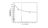
図12は、本実施形態の効果を説明する図である。
図11に示したようにTCS制御のみを行った場合では、スプリットμ路で発進加速し、左右駆動輪の何れかにスリップが発生した場合、TCS制御が作動されて、スリップ輪のスリップ率λがスリップ率閾値λTH以下となるようにスリップ輪側の出力トルクのみが減少制御される。したがって、例えば、左右駆動輪のスリップ率λが共にスリップ率閾値λTH以下の0.1となったとき、車両の走行状態は低μ路側では点Aの状態、高μ路側では点Bの状態となる。このとき、左右駆動輪で車輪から路面に伝わる駆動力に大きな差があり、ステアリングを直進位置に維持している場合であっても車両は低μ路側へ旋回してしまう。
FIG. 12 is a diagram for explaining the effect of this embodiment.
In the case where only TCS control is performed as shown in FIG. 11, when the vehicle starts and accelerates on a split μ road and slip occurs on any of the left and right drive wheels, the TCS control is activated and the slip ratio λ of the slip wheel is Only the output torque on the slip wheel side is controlled to decrease so that becomes less than the slip ratio threshold λ TH . Therefore, for example, when the slip ratio λ of the left and right drive wheels is both 0.1, which is equal to or less than the slip ratio threshold λ TH , the running state of the vehicle is a point A state on the low μ road side and a point B state on the high μ road side. It becomes. At this time, there is a large difference in the driving force transmitted from the wheels to the road surface between the left and right driving wheels, and the vehicle turns to the low μ road side even when the steering is maintained at the straight traveling position.
このように、車両の走行状態は低μ路側では点Aの状態となり、高μ路側では点Bの状態となるので、摩擦係数比で約2.4倍の駆動力差が発生してしまう。
これに対して本実施形態では、スプリットμ路で発進加速し、左右駆動輪の何れかにスリップが発生した場合、TCS制御が作動されて、スリップ輪のスリップ率λがスリップ率閾値λTH以下となるようにスリップ輪側の出力トルクを減少制御すると共に、左右駆動力差が0となるように非スリップ輪の出力トルクを減少制御する。したがって、左右駆動輪のスリップが抑制されたとき、車両の走行状態は低μ路側では点Aの状態、高μ路側では点Cの状態となる。このとき、左右駆動輪で車輪から路面に伝わる駆動力は等しいため、ステアリングを直進位置に維持している場合、車両挙動が不安定になることなく直進方向に発進する。
As described above, the traveling state of the vehicle is in the state of point A on the low μ road side and in the state of point B on the high μ road side, so that a driving force difference of about 2.4 times in friction coefficient ratio occurs.
On the other hand, in this embodiment, when the vehicle starts and accelerates on the split μ road and a slip occurs in any of the left and right drive wheels, the TCS control is activated and the slip ratio λ of the slip wheel is equal to or less than the slip ratio threshold λ TH. The output torque on the slip wheel side is reduced and controlled so that the difference between the left and right driving forces is zero. Therefore, when the slip of the left and right drive wheels is suppressed, the running state of the vehicle is in the state of point A on the low μ road side and in the state of point C on the high μ road side. At this time, since the driving force transmitted from the wheels to the road surface is equal between the left and right driving wheels, when the steering is maintained at the straight traveling position, the vehicle starts moving in the straight traveling direction without becoming unstable.
このように、本実施形態では、高μ路側の駆動輪の出力トルクを制御して、低μ路側では点Aの状態、高μ路側では点Cの状態とするので、左右駆動輪の駆動力差をなくすことができ、運転者の意図しないヨーモーメントが発生することを抑制することができる。
本実施形態において、アクセルペダルセンサ12が運転操作量検出手段を構成し、モータインバータ4RL,4RRがモータ動作検出手段を構成する。また、図4のステップS1が駆動力算出手段を構成し、ステップS3がスリップ率算出手段及び駆動力制御手段を構成し、ステップS6の処理が第2補正量算出手段を構成し、ステップS7の処理が第1補正量算出手段を構成し、ステップS6及びステップS7の処理が制御量補正手段を構成する。
As described above, in this embodiment, the output torque of the driving wheel on the high μ road side is controlled to be in the state of point A on the low μ road side and in the state of point C on the high μ road side. The difference can be eliminated and the occurrence of a yaw moment unintended by the driver can be suppressed.
In the present embodiment, the
(第1の実施形態の効果)
(1)左右駆動輪から路面に伝達される駆動力の差が目標駆動力差となるようにTCS制御量を補正する。したがって、TCS制御によって左右駆動輪の何れか一方の駆動力がドライバ指令値より小さくなった場合に、他方の駆動輪の駆動力が制御されて、前記駆動力差が目標駆動力差に追従される。その結果、例えば、スプリットμ路での発進加速において、TCS制御によって低μ路側の駆動輪の駆動力が減少制御された場合に、低μ路側の駆動輪から路面に伝達される駆動力が高μ路側と比較して小さくなることに起因して車両が低μ路側に旋回してしまうなど、運転者の意図しないヨーモーメントが発生することを抑制することができる。
(Effects of the first embodiment)
(1) The TCS control amount is corrected so that the difference in driving force transmitted from the left and right driving wheels to the road surface becomes the target driving force difference. Therefore, when the driving force of one of the left and right driving wheels becomes smaller than the driver command value by the TCS control, the driving force of the other driving wheel is controlled so that the driving force difference follows the target driving force difference. The As a result, for example, in the start acceleration on the split μ road, when the driving force of the driving wheel on the low μ road side is reduced by TCS control, the driving force transmitted from the driving wheel on the low μ road side to the road surface is high. It is possible to suppress the occurrence of a yaw moment unintended by the driver, such as the vehicle turning to the low μ road side due to being smaller than the μ road side.
(2)左右駆動輪から路面に伝わる駆動力差が目標駆動力差となるようにする駆動力差制御はフィードバック制御とフィードフォワード制御とを併用して行う。したがって、左右駆動輪の駆動力差をより適切に目標駆動力差に追従させることができる。
また、過去の所定の参照期間における電動モータの出力駆動力の変化と、当該参照期間における駆動輪から路面に伝達される駆動力の変化とから求まる駆動力伝達特性を用いて、前記駆動輪から路面に伝達される将来の駆動力を推定する。したがって、電動モータの出力特性を正確にモデリングできる性質を生かして、精度良く将来の駆動力を推定することができる。
(2) The driving force difference control in which the driving force difference transmitted from the left and right driving wheels to the road surface becomes the target driving force difference is performed by using both feedback control and feedforward control. Therefore, the driving force difference between the left and right driving wheels can be made to follow the target driving force difference more appropriately.
In addition, from the driving wheel using the driving force transmission characteristics obtained from the change in the output driving force of the electric motor in the past predetermined reference period and the change in the driving force transmitted from the driving wheel to the road surface in the reference period. Estimate the future driving force transmitted to the road surface. Therefore, it is possible to accurately estimate the future driving force by taking advantage of the property of accurately modeling the output characteristics of the electric motor.
(3)TCS制御介入時に、左右駆動輪から路面に伝達される駆動力の差を、運転者が意図したヨーモーメントを発生するための目標駆動力差に追従させる。したがって、TCS制御によって左右駆動輪の何れか一方の駆動力がドライバ指令値より小さくなった場合でも、他方の駆動輪の駆動力を制御することで、運転者の意図しないヨーモーメントが発生することを抑制することができ、車両挙動を安定させることができる。 (3) At the time of TCS control intervention, the difference in driving force transmitted from the left and right driving wheels to the road surface is made to follow the target driving force difference for generating the yaw moment intended by the driver. Therefore, even if the driving force of one of the left and right driving wheels becomes smaller than the driver command value by TCS control, the yaw moment unintended by the driver is generated by controlling the driving force of the other driving wheel. Can be suppressed, and the vehicle behavior can be stabilized.
(4)TCS制御によって左右駆動輪の何れか一方の駆動力がドライバ指令値より小さくなった場合に、左右駆動輪から路面に伝達される駆動力の差が目標駆動力差に追従するように、他方の駆動輪の駆動力を制御する。したがって、運転者の意図しないヨーモーメントが発生することを抑制することができ、車両挙動を安定させることが可能な自動車とすることができる。 (4) When the driving force of one of the left and right driving wheels becomes smaller than the driver command value by the TCS control, the difference in driving force transmitted from the left and right driving wheels to the road surface follows the target driving force difference. The driving force of the other driving wheel is controlled. Therefore, generation of a yaw moment not intended by the driver can be suppressed, and an automobile capable of stabilizing the vehicle behavior can be obtained.
(5)TCS制御によって左右駆動輪の何れか一方の駆動力がドライバ指令値より小さくなった場合に、左右駆動輪から路面に伝達される駆動力の差が目標駆動力差に追従するように、他方の駆動輪の駆動力を制御することで、運転者の意図しないヨーモーメントが発生することを抑制することができ、車両挙動を安定させることができる。 (5) When the driving force of one of the left and right driving wheels becomes smaller than the driver command value by the TCS control, the difference in the driving force transmitted from the left and right driving wheels to the road surface follows the target driving force difference. By controlling the driving force of the other drive wheel, it is possible to suppress the yaw moment that is not intended by the driver, and to stabilize the vehicle behavior.
(第2の実施形態)
次に、本発明の第2の実施形態について説明する。
(構成)
この第2の実施形態は、路面の駆動力伝達特性を算出するサンプリング時間を、TCS制御量に応じて、言い換えると電動モータの出力駆動力の変化量に対する駆動輪から路面へ伝わる駆動力の変化量に応じて変更するようにしたものである。
(Second Embodiment)
Next, a second embodiment of the present invention will be described.
(Constitution)
In the second embodiment, the sampling time for calculating the driving force transmission characteristic of the road surface is changed according to the TCS control amount, in other words, the change of the driving force transmitted from the driving wheel to the road surface with respect to the change amount of the output driving force of the electric motor. It is changed according to the amount.
図13は、第2の実施形態におけるコントロールユニット20で実行される駆動力制御処理手順を示すフローチャートである。本実施形態の駆動力制御処理では、図4に示す前述した第1の実施形態の駆動力制御処理において、ステップS8の後に路面の駆動力伝達特性を算出するサンプリング時間を設定するステップS21を追加したことを除いては、図4に示す第1の実施形態における駆動力制御と同様の処理を実行する。そこで、第1の実施形態における駆動力制御と同様の処理を実行する部分には同一ステップ番号を付し、処理の異なる部分を中心に説明する。
FIG. 13 is a flowchart showing a driving force control processing procedure executed by the
ステップS21では、電動モータの出力駆動力の変化ΔKIに対する駆動輪から路面へ伝わる駆動力の変化ΔTdに基づいて、路面の駆動力伝達特性を算出するサンプリング時間を設定する。
図14は、駆動力伝達特性を算出するサンプリング時間の設定方法を説明するための図である。
In step S21, a sampling time for calculating the road surface driving force transmission characteristic is set based on the driving force change ΔTd transmitted from the driving wheel to the road surface with respect to the output driving force change ΔKI of the electric motor.
FIG. 14 is a diagram for explaining a sampling time setting method for calculating driving force transmission characteristics.
所定期間における電動モータの出力駆動力の変化ΔKIに対する駆動輪から路面へ伝わる駆動力の変化ΔTdは図14の領域[1]〜[3]で夫々異なり、領域[1]でのΔTd/ΔKIの値は絶対値が小さい負の値であり、領域[2]でのΔTd/ΔKIの値は領域[1]でのΔTd/ΔKIの値と比較して絶対値の大きい負の値であり、領域[3]でのΔTd/ΔKIの値は絶対値の大きい正の値となる。 The change ΔTd in the driving force transmitted from the driving wheel to the road surface with respect to the change ΔKI in the output driving force of the electric motor in the predetermined period is different in each of the areas [1] to [3] in FIG. 14, and ΔTd / ΔKI in the area [1] is different. The value is a negative value having a small absolute value, and the value of ΔTd / ΔKI in the region [2] is a negative value having a large absolute value compared to the value of ΔTd / ΔKI in the region [1]. The value of ΔTd / ΔKI in [3] is a positive value having a large absolute value.
車両の走行状態が領域[1]内の状態である場合には、ΔTd/ΔKIの絶対値が小さいため、駆動力伝達特性ΔTd/ΔKIを算出するΔKIの区間を長く取っても十分な精度で駆動力伝達特性ΔTd/ΔKIを算出することができる。したがって、電動モータの出力駆動力の変化ΔKIに対する駆動輪から路面へ伝わる駆動力の変化ΔTdが小さい場合には、駆動力伝達特性を算出するサンプリング時間TをT=T1に設定する。 When the traveling state of the vehicle is in the state [1], the absolute value of ΔTd / ΔKI is small, so that even if the ΔKI section for calculating the driving force transmission characteristic ΔTd / ΔKI is long, the accuracy is sufficiently high. The driving force transmission characteristic ΔTd / ΔKI can be calculated. Therefore, when the change ΔTd in the driving force transmitted from the driving wheel to the road surface with respect to the change ΔKI in the output driving force of the electric motor is small, the sampling time T for calculating the driving force transmission characteristic is set to T = T1.
一方、電動モータの出力駆動力の変化ΔKIに対する駆動輪から路面へ伝わる駆動力の変化ΔTdが大きい場合は、ΔKIの区間を短くして駆動力伝達特性ΔTd/ΔKIが逐次更新されるようにする。したがって、この場合には、駆動力伝達特性を算出するサンプリング時間TをT=T2(<T1)に設定する。
なお、車両の走行状態が図14のどの領域内にあるかに応じて、サンプリング時間Tを段階的に変更する場合について説明したが、電動モータの出力駆動力の変化ΔKIに対する駆動輪から路面へ伝わる駆動力の変化ΔTdの大きさに応じて、サンプリング時間Tを連続的に変更することもできる。
On the other hand, when the change ΔTd in the driving force transmitted from the driving wheel to the road surface with respect to the change ΔKI in the output driving force of the electric motor is large, the ΔKI interval is shortened so that the driving force transfer characteristic ΔTd / ΔKI is sequentially updated. . Therefore, in this case, the sampling time T for calculating the driving force transmission characteristic is set to T = T2 (<T1).
In addition, although the case where the sampling time T is changed stepwise according to which region in FIG. 14 is in the traveling state of the vehicle has been described, from the driving wheel to the road surface with respect to the change ΔKI in the output driving force of the electric motor. The sampling time T can be changed continuously according to the magnitude of the transmitted driving force change ΔTd.
このようにステップS21では、電動モータの出力駆動力の変化ΔKIに対する駆動輪から路面へ伝わる駆動力の変化ΔTdに応じてサンプリング時間Tを変更してから駆動力制御処理を終了する。 Thus, in step S21, after changing the sampling time T in accordance with the change ΔTd in the driving force transmitted from the driving wheel to the road surface with respect to the change ΔKI in the output driving force of the electric motor, the driving force control process ends.
(動作)
次に、本発明における第2の実施形態の動作について説明する。
車両1がスプリットμ路に停止している状態から、運転者が車両を発進させようとしてアクセルペダルを踏み込み、車両1の左駆動輪2RLがスリップして、駆動輪2RLにスリップ率閾値λTHを超えるスリップ率λが発生したものとする。この場合、コントロールユニット20は、図4のステップ2でアクセルペダル操作量ACCに基づいてドライバ指令トルクTACCを算出する。駆動輪2RLのスリップ率λはスリップ率閾値λTHを超えているため、ステップS3で、コントロールユニット20は、駆動輪2RLのスリップ率λがスリップ率閾値λTH以下となるように電動モータ3RLの出力トルクを制御するための駆動トルク指令TTCSを算出する。
(Operation)
Next, the operation of the second embodiment of the present invention will be described.
From the state where the
また、コントロールユニット20は、ステップS6で駆動力伝達特性ΔTd/ΔKIと次回の電動モータ3RLの出力駆動力Fmとに基づいて次回の左駆動輪2RLの駆動力Tdを推定し、推定した駆動力Tdに基づいて左右駆動力差を0とするためのフィードフォワード補正量TFFを算出する。
さらにコントロールユニット20は、ステップS7で現在の左右駆動力差と目標駆動力差との偏差に基づいて、現在の左右駆動力差を目標駆動力差と一致させるためのフィードバック補正量TFBを算出する。
Further, in step S6, the
Further, in step S7, the
これにより、コントロールユニット20では、車両の加速スリップを抑制するためのTCS制御と、左右駆動力差を0とするための駆動力差制御とが実行されることになり、駆動トルク指令TTCSをフィードフォワード補正量TFF及びフィードバック補正量TFBで補正した駆動トルク指令に基づいた駆動信号がモータインバータ4RL,4RRに出力される。
As a result, the
また、このとき左駆動輪2RLのスリップ率λが大きく、車両の走行状態が図14の領域[1]内の状態であり、電動モータの出力駆動力の変化ΔKIに対する駆動輪から路面へ伝わる駆動力の変化ΔTdが小さいものとすると、コントロールユニット20はステップS21で駆動力伝達特性を算出するサンプリング時間Tを比較的長いT=T1に設定する。
Further, at this time, the slip ratio λ of the left drive wheel 2RL is large, the vehicle is in the state [1] in FIG. 14, and the drive transmitted from the drive wheel to the road surface with respect to the change ΔKI in the output drive force of the electric motor. If the force change ΔTd is small, the
そして、次回の駆動力制御処理フローの実行時には、コントロールユニット20はステップS6で、1サンプリング前のステップS21で設定されたサンプリング時間T=T1に基づいてΔKIの区間を長く取り、駆動力伝達特性ΔTd/ΔKIを算出する。
その後、左駆動輪2RLのスリップ率λが徐々に抑制されて、車両の走行状態が図14の領域[2]内の状態に移行すると、電動モータの出力駆動力の変化ΔKIに対する駆動輪から路面へ伝わる駆動力の変化ΔTdが大きくなるため、コントロールユニット20はステップS21で駆動力伝達特性を算出するサンプリング時間Tを比較的短いT=T2に設定する。
When the next driving force control processing flow is executed, the
Thereafter, when the slip ratio λ of the left drive wheel 2RL is gradually suppressed and the vehicle traveling state shifts to the state in the region [2] in FIG. 14, the road surface from the drive wheel to the change ΔKI in the output driving force of the electric motor. Therefore, the
これにより、次回の駆動力制御処理フローの実行時には、コントロールユニット20はステップS6で、1サンプリング前のステップS21で設定されたサンプリング時間T=T2に基づいてΔKIの区間を短く取り、駆動力伝達特性ΔTd/ΔKIを算出する。
このように、電動モータの出力駆動力の変化ΔKIに対する路面摩擦係数μの変化(駆動輪から路面へ伝わる駆動力の変化ΔTd)が少ない区間では、駆動力伝達特性を算出するサンプリング時間Tを長く取って、次回の駆動輪から路面へ伝わる駆動力Tdの推定区間を大きく取るので、推定誤差に対してロバストな推定ができる。
なお、上記実施形態においては、ステップS21の処理が参照期間設定手段を構成している。
As a result, when the next driving force control processing flow is executed, the
As described above, in the section where the change in the road surface friction coefficient μ with respect to the change ΔKI in the output driving force of the electric motor (change ΔTd in the driving force transmitted from the driving wheel to the road surface) is small, the sampling time T for calculating the driving force transmission characteristic is lengthened. Therefore, since a large estimation section of the driving force Td transmitted from the next driving wheel to the road surface is taken, a robust estimation can be made with respect to the estimation error.
In the above embodiment, the process of step S21 constitutes a reference period setting unit.
(第2の実施形態の効果)
(1)路面の駆動力伝達特性を算出するサンプリング時間を、電動モータの出力駆動力の変化量に対する駆動輪から路面へ伝わる駆動力の変化量に応じて変更する。したがって、電動モータの出力駆動力の変化量に対する駆動輪から路面へ伝わる駆動力の変化量が小さい場合には、サンプリング時間を長くとって、駆動輪から路面に伝わる将来の駆動力の推定においてロバストな推定ができる。
(Effect of 2nd Embodiment)
(1) The sampling time for calculating the driving force transmission characteristic of the road surface is changed according to the change amount of the driving force transmitted from the driving wheel to the road surface with respect to the change amount of the output driving force of the electric motor. Therefore, if the amount of change in the driving force transmitted from the driving wheel to the road surface relative to the amount of change in the output driving force of the electric motor is small, a longer sampling time is used for robust estimation of the future driving force transmitted from the driving wheel to the road surface. Can be estimated.
(第3の実施形態)
次に、本発明の第3の実施形態について説明する。
(構成)
この第3の実施形態は、駆動力伝達特性に応じてTCS制御の最大制御量を変更するようにしたものである。
(Third embodiment)
Next, a third embodiment of the present invention will be described.
(Constitution)
In the third embodiment, the maximum control amount of TCS control is changed according to the driving force transmission characteristics.
図15は、第3の実施形態におけるコントロールユニット20で実行される駆動力制御処理手順を示すフローチャートである。本実施形態の駆動力制御処理では、図4に示す前述した第1の実施形態の駆動力制御処理において、ステップS8の後にTCS制御の最大制御量を設定するステップS31を追加したことを除いては、図4に示す第1の実施形態における駆動力制御と同様の処理を実行する。そこで、第1の実施形態における駆動力制御と同様の処理を実行する部分には同一ステップ番号を付し、処理の異なる部分を中心に説明する。
FIG. 15 is a flowchart showing a driving force control processing procedure executed by the
ステップS31では、前記ステップS6で算出される駆動力伝達特性ΔTd/ΔKIに応じてTCS制御量の上限に相当する最大制御量を設定してから、駆動力制御処理を終了する。
図14において、領域[3]がTCS制御における目標スリップ率の範囲(スリップ率閾値λTH以下の領域)であり、領域[3]での駆動力伝達特性ΔTd/KIの値は正の所定値TH以上となる。
In step S31, the maximum control amount corresponding to the upper limit of the TCS control amount is set according to the driving force transmission characteristic ΔTd / ΔKI calculated in step S6, and then the driving force control process is terminated.
In FIG. 14, region [3] is the range of the target slip ratio in the TCS control (region of slip ratio threshold λ TH or less), and the value of driving force transfer characteristic ΔTd / KI in region [3] is a positive predetermined value. TH or higher.
ΔTd/KI≧THであり、駆動力伝達特性ΔTd/KIが領域[3]内にある場合にはTCS制御の最大値を小さい値に設定し、駆動力伝達特性ΔTd/KIが領域[3]外にある場合にはTCS制御量の最大値を大きい値に設定する。
前記ステップS3では、このステップS31で設定した最大制御量によって、TCS制御量TTCSに上限を設ける。
When ΔTd / KI ≧ TH and the driving force transmission characteristic ΔTd / KI is in the region [3], the maximum value of the TCS control is set to a small value, and the driving force transmission characteristic ΔTd / KI is in the region [3]. If it is outside, the maximum value of the TCS control amount is set to a large value.
In step S3, an upper limit is set for the TCS control amount T TCS according to the maximum control amount set in step S31.
(動作)
次に、本発明における第3の実施形態の動作について説明する。
車両1が凍結路に停止している状態から、運転者が車両を発進させようとしてアクセルペダルを踏み込み、車両1の駆動輪2RL及び2RRにスリップ率閾値λTHを超えるスリップ率λが発生したものとする。この場合、コントロールユニット20は、図4のステップ2でアクセルペダル操作量ACCに基づいてドライバ指令トルクTACCを算出する。駆動輪2RL,2RRのスリップ率λはスリップ率閾値λTHを超えているため、ステップS3で、コントロールユニット20は、駆動輪2RL,2RRのスリップ率λがスリップ率閾値λTH以下となるように電動モータ3RL,3RRの出力トルクを制御するための駆動トルク指令TTCSを算出する。
(Operation)
Next, the operation of the third embodiment of the present invention will be described.
When the
左駆動輪2RLの路面摩擦係数と、右駆動輪2RRの路面摩擦係数とが等しく、車輪から路面に伝達される駆動力は左右駆動輪で差がないため、コントロールユニット20は、ステップS6でフィードフォワード補正量TFFを0とすると共に、ステップS7でフィードバック補正量TFBを0とする。
これにより、コントロールユニット20では、車両の加速スリップを抑制するためのTCS制御のみが実行されることになり、駆動トルク指令TTCSに基づいた駆動信号がモータインバータ4RL,4RRに出力される。
Since the road surface friction coefficient of the left driving wheel 2RL and the road surface friction coefficient of the right driving wheel 2RR are equal and the driving force transmitted from the wheel to the road surface is not different between the left and right driving wheels, the
Thereby, in the
このとき駆動輪2RL,2RRのスリップ率λが大きく、前記ステップS6で算出された駆動力伝達特性ΔTd/ΔKIが正の所定値TH以上となっておらず、車両の走行状態が図14の領域[3]外の状態であるものとすると、コントロールユニット20はステップS31でTCS制御の最大制御量を比較的比較的大きい値に設定する。
そして、次回の駆動力制御処理フローの実行時には、コントロールユニット20はステップS3で、1サンプリング前のステップS31で設定された最大制御量に基づいて、TCS制御量TTCSの上限を大きく設ける。
At this time, the slip ratio λ of the driving wheels 2RL and 2RR is large, the driving force transmission characteristic ΔTd / ΔKI calculated in step S6 is not equal to or greater than the positive predetermined value TH, and the running state of the vehicle is the region shown in FIG. [3] If it is assumed that the state is outside, the
When the next driving force control processing flow is executed, the
その後、駆動輪2RL,2RRのスリップ率λが徐々に抑制されて、車両の走行状態が図14の領域[3]内の状態に移行すると、ΔTd/ΔKI≦THとなるため、コントロールユニット20はステップS31で、TCS制御量の最大値を小さく設定する。
これにより、次回の駆動力制御処理フローの実行時には、コントロールユニット20はステップS3で、1サンプリング前のステップS31で設定された最大制御量に基づいて、TCS制御量TTCSの上限を小さく設ける。
After that, when the slip ratio λ of the drive wheels 2RL and 2RR is gradually suppressed and the vehicle traveling state shifts to the state in the region [3] in FIG. 14, ΔTd / ΔKI ≦ TH, so the
Thereby, at the time of execution of the next driving force control processing flow, the
このように、領域[3]外の状態にある場合には、TCS制御量の最大値を大きく設定することでTCS制御を大きく作動することができるので、スリップ輪の加速スリップを迅速に抑制して目標スリップ率の範囲である領域[3]内に早く収束させることができる。また同時に、上記の処理により、領域[3]の区間の電動モータの出力駆動力KIと駆動輪から路面へ伝わる駆動力Tdの値を細かく観察することができるようになるので、駆動力伝達特性ΔTd/KIが大きく変化する部分での線形性を維持しやすくなる。
なお、上記実施形態においては、ステップS31の処理が最大制御量設定手段を構成している。
As described above, when the state is outside the region [3], the TCS control can be operated largely by setting the maximum value of the TCS control amount to a large value, so that the acceleration slip of the slip ring can be quickly suppressed. Thus, it is possible to quickly converge within the region [3] that is the range of the target slip ratio. At the same time, the above processing makes it possible to finely observe the value of the output driving force KI of the electric motor and the driving force Td transmitted from the driving wheel to the road surface in the section of region [3]. It becomes easy to maintain the linearity in the portion where ΔTd / KI greatly changes.
In the above embodiment, the process in step S31 constitutes a maximum control amount setting means.
(第3の実施形態の効果)
(1)TCS制御量の最大制御量を、電動モータの出力駆動力の変化量に対する駆動輪から路面へ伝わる駆動力の変化量に応じて変更する。したがって、電動モータの出力駆動力の変化量に対する駆動輪から路面へ伝わる駆動力の変化量に基づいて、スリップ輪のスリップ率が目標スリップ率の範囲内にないと判断した場合には、前記最大制御量を大きく設定してTCS制御を大きく作動することで、スリップ輪の加速スリップを迅速に抑制して目標スリップ率の範囲内に早く収束させることができる。
また、微小区間の線形性を維持しやすくなると共に、最適な駆動力付近でTCS制御量が緻密になるので、より適切な駆動力制御を行うことができる。
(Effect of the third embodiment)
(1) The maximum control amount of the TCS control amount is changed according to the change amount of the driving force transmitted from the driving wheel to the road surface with respect to the change amount of the output driving force of the electric motor. Therefore, if it is determined that the slip ratio of the slip wheel is not within the range of the target slip ratio based on the change amount of the drive force transmitted from the drive wheel to the road surface with respect to the change amount of the output drive force of the electric motor, the maximum By setting the control amount large and operating the TCS control greatly, it is possible to quickly suppress the acceleration slip of the slip wheel and to quickly converge the target slip ratio within the range.
In addition, it becomes easy to maintain the linearity of the minute section, and the TCS control amount becomes dense near the optimum driving force, so that more appropriate driving force control can be performed.
(応用例)
なお、上記各実施形態においては、車輪と一体に設計された所謂インホイールモータを駆動輪に独立に設置する場合について説明したが、インホイールモータを適用せずに各駆動輪の駆動力を独立に制御可能なモータを夫々設置することもできる。この場合にも、車体の左右にかかる駆動力を独立に制御できるので、本発明を適用可能である。
(Application examples)
In each of the above embodiments, a case where a so-called in-wheel motor designed integrally with a wheel is installed on a driving wheel independently has been described. However, the driving force of each driving wheel is independently applied without applying the in-wheel motor. Controllable motors can also be installed respectively. Also in this case, since the driving force applied to the left and right sides of the vehicle body can be controlled independently, the present invention can be applied.
また、上記各実施形態においては、後二輪を駆動輪とする後輪駆動車に本発明を適用する場合について説明したが、前輪駆動車や四輪駆動車に適用することもできる。 In each of the above-described embodiments, the case where the present invention is applied to a rear wheel drive vehicle using the rear two wheels as drive wheels has been described. However, the present invention can also be applied to a front wheel drive vehicle and a four wheel drive vehicle.
1 車両
2RL,2RR 駆動輪
3RL,3RR 電動モータ
4RL,4RR モータインバータ
10 ステアリングホイール
11 操舵角センサ
12 アクセルペダルセンサ
13 ブレーキペダルセンサ
14 車両挙動センサ
20 コントロールユニット
21 電源ユニット
DESCRIPTION OF
Claims (7)
前記電動モータの動作状態を検出するモータ動作検出手段と、該モータ動作検出手段で検出された前記電動モータの動作状態に基づいて、前記左右駆動輪から路面に伝達される駆動力を夫々算出する駆動力算出手段と、該駆動力算出手段で算出された左右駆動輪の駆動力の差が所定の目標駆動力差となるように、前記駆動力制御手段による駆動力制御の制御量を補正する制御量補正手段とを備えることを特徴とする電動車両の駆動力制御装置。 Left and right electric motors for independently driving the left and right drive wheels, operation amount detection means for detecting the amount of driving operation by the driver, slip ratio calculation means for calculating the slip ratio of the drive wheels, and slip of the drive wheels In a driving force control device for an electric vehicle comprising driving force control means for controlling the output driving force of each electric motor according to the detection result of the operation amount detection means so that the rate falls within a predetermined range,
Based on the motor operation detection means for detecting the operation state of the electric motor and the operation state of the electric motor detected by the motor operation detection means, the driving force transmitted from the left and right drive wheels to the road surface is calculated. The control amount of the driving force control by the driving force control unit is corrected so that the difference between the driving force of the driving force calculation unit and the driving force of the left and right driving wheels calculated by the driving force calculation unit becomes a predetermined target driving force difference. A driving force control apparatus for an electric vehicle, comprising: a control amount correction unit.
前記駆動力制御介入時に、前記左右駆動輪から路面に伝達される駆動力の差を、運転者が意図したヨーモーメントを発生するための目標駆動力差に追従させる駆動力差制御手段を備えることを特徴とする電動車両の駆動力制御装置。 A drive force control device for an electric vehicle that performs drive force control for controlling an electric motor that is a drive source of the drive wheels so that the slip ratio of the left and right drive wheels is within a predetermined range,
A driving force difference control means for causing a difference in driving force transmitted from the left and right driving wheels to a road surface to follow a target driving force difference for generating a yaw moment intended by the driver during the driving force control intervention; A driving force control device for an electric vehicle.
前記電動モータの動作状態を検出するモータ動作検出手段と、該モータ動作検出手段で検出された前記電動モータの動作状態に基づいて、前記左右駆動輪から路面に伝達される駆動力を夫々算出する駆動力算出手段と、該駆動力算出手段で算出された左右駆動輪の駆動力の差が所定の目標駆動力差となるように、前記駆動力制御手段による駆動力制御の制御量を補正する制御量補正手段とを備えることを特徴とする自動車。 A driving force control device for an electric vehicle having driving force control means for controlling an electric motor that is a driving source of the driving wheel so that a slip ratio of the driving wheel of the vehicle generated by the driver's accelerator operation is within a predetermined range. A car equipped with
Based on the motor operation detection means for detecting the operation state of the electric motor and the operation state of the electric motor detected by the motor operation detection means, the driving force transmitted from the left and right drive wheels to the road surface is calculated. The control amount of the driving force control by the driving force control unit is corrected so that the difference between the driving force of the driving force calculation unit and the driving force of the left and right driving wheels calculated by the driving force calculation unit becomes a predetermined target driving force difference. An automobile comprising a control amount correcting means.
前記電動モータの動作状態に基づいて、前記左右駆動輪から路面に伝達される駆動力を夫々算出し、該左右駆動輪の駆動力の差が所定の目標駆動力差となるように、前記駆動力制御の制御量を補正することを特徴とする電動車両の駆動力制御方法。 A drive force control method for an electric vehicle that performs drive force control for controlling an electric motor that is a drive source of the drive wheels so that a slip ratio of the left and right drive wheels is within a predetermined range,
The driving force transmitted from the left and right driving wheels to the road surface is calculated based on the operating state of the electric motor, and the driving force is set so that the difference between the driving forces of the left and right driving wheels becomes a predetermined target driving force difference. A driving force control method for an electric vehicle, wherein a control amount of force control is corrected.
Priority Applications (1)
| Application Number | Priority Date | Filing Date | Title |
|---|---|---|---|
| JP2006022193A JP4867369B2 (en) | 2006-01-31 | 2006-01-31 | Driving force control device for electric vehicle, automobile and driving force control method for electric vehicle |
Applications Claiming Priority (1)
| Application Number | Priority Date | Filing Date | Title |
|---|---|---|---|
| JP2006022193A JP4867369B2 (en) | 2006-01-31 | 2006-01-31 | Driving force control device for electric vehicle, automobile and driving force control method for electric vehicle |
Publications (2)
| Publication Number | Publication Date |
|---|---|
| JP2007209068A true JP2007209068A (en) | 2007-08-16 |
| JP4867369B2 JP4867369B2 (en) | 2012-02-01 |
Family
ID=38488028
Family Applications (1)
| Application Number | Title | Priority Date | Filing Date |
|---|---|---|---|
| JP2006022193A Expired - Fee Related JP4867369B2 (en) | 2006-01-31 | 2006-01-31 | Driving force control device for electric vehicle, automobile and driving force control method for electric vehicle |
Country Status (1)
| Country | Link |
|---|---|
| JP (1) | JP4867369B2 (en) |
Cited By (14)
| Publication number | Priority date | Publication date | Assignee | Title |
|---|---|---|---|---|
| JP2007336679A (en) * | 2006-06-14 | 2007-12-27 | Nissan Motor Co Ltd | Driving force estimator for electric vehicle, and method of estimating driving force of automobile or electric vehicle |
| WO2012005264A1 (en) * | 2010-07-09 | 2012-01-12 | 日産自動車株式会社 | Device for controlling torque distribution to left and right wheels on a vehicle |
| JP2013541933A (en) * | 2010-11-04 | 2013-11-14 | キャタピラー インコーポレイテッド | System and method for controlling wheel motor torque in an electric drive system |
| JP2014192925A (en) * | 2013-03-26 | 2014-10-06 | Meidensha Corp | Controlling device for cart in which each wheel is driven independently |
| WO2014162462A1 (en) * | 2013-04-01 | 2014-10-09 | パイオニア株式会社 | Traction control device and traction control method |
| WO2014188489A1 (en) * | 2013-05-20 | 2014-11-27 | パイオニア株式会社 | Traction control device and traction control method |
| WO2015037615A1 (en) * | 2013-09-12 | 2015-03-19 | 日立オートモティブシステムズ株式会社 | Driving force control device and driving force control method |
| WO2015190349A1 (en) * | 2014-06-09 | 2015-12-17 | Ntn株式会社 | Drive control device with traction control function for right-left independent drive vehicle |
| DE102015116041A1 (en) | 2014-09-30 | 2016-03-31 | Fuji Jukogyo Kabushiki Kaisha | Device and method for controlling vehicles |
| WO2016093102A1 (en) * | 2014-12-08 | 2016-06-16 | Ntn株式会社 | Vehicle braking and driving force control device |
| CN106394308A (en) * | 2015-07-30 | 2017-02-15 | 丰田自动车株式会社 | Electric vehicle |
| CN108248455A (en) * | 2016-12-29 | 2018-07-06 | 比亚迪股份有限公司 | The Anti-slip regulation control method and device of four-drive electric car |
| US11104312B2 (en) | 2018-12-03 | 2021-08-31 | Toyota Jidosha Kabushiki Kaisha | Vehicle control apparatus |
| CN116278814A (en) * | 2023-05-19 | 2023-06-23 | 成都赛力斯科技有限公司 | Automobile stability control method and device based on slip rate and new energy automobile |
Citations (6)
| Publication number | Priority date | Publication date | Assignee | Title |
|---|---|---|---|---|
| JPH05176418A (en) * | 1991-03-25 | 1993-07-13 | Hitachi Ltd | Controller for electric automobile |
| JPH1084605A (en) * | 1996-09-10 | 1998-03-31 | Toyota Motor Corp | Drive controller for electric car |
| JPH11125129A (en) * | 1997-10-21 | 1999-05-11 | Toyota Motor Corp | Vehicle |
| WO2003095261A1 (en) * | 2002-05-07 | 2003-11-20 | Kabushiki Kaisha Bridgestone | Method and device for controlling vehicle |
| JP2004336910A (en) * | 2003-05-08 | 2004-11-25 | Toyota Motor Corp | Driving control device for vehicle |
| JP2005160262A (en) * | 2003-11-28 | 2005-06-16 | Toyota Motor Corp | Driving force control device for vehicle |
-
2006
- 2006-01-31 JP JP2006022193A patent/JP4867369B2/en not_active Expired - Fee Related
Patent Citations (6)
| Publication number | Priority date | Publication date | Assignee | Title |
|---|---|---|---|---|
| JPH05176418A (en) * | 1991-03-25 | 1993-07-13 | Hitachi Ltd | Controller for electric automobile |
| JPH1084605A (en) * | 1996-09-10 | 1998-03-31 | Toyota Motor Corp | Drive controller for electric car |
| JPH11125129A (en) * | 1997-10-21 | 1999-05-11 | Toyota Motor Corp | Vehicle |
| WO2003095261A1 (en) * | 2002-05-07 | 2003-11-20 | Kabushiki Kaisha Bridgestone | Method and device for controlling vehicle |
| JP2004336910A (en) * | 2003-05-08 | 2004-11-25 | Toyota Motor Corp | Driving control device for vehicle |
| JP2005160262A (en) * | 2003-11-28 | 2005-06-16 | Toyota Motor Corp | Driving force control device for vehicle |
Cited By (39)
| Publication number | Priority date | Publication date | Assignee | Title |
|---|---|---|---|---|
| JP2007336679A (en) * | 2006-06-14 | 2007-12-27 | Nissan Motor Co Ltd | Driving force estimator for electric vehicle, and method of estimating driving force of automobile or electric vehicle |
| WO2012005264A1 (en) * | 2010-07-09 | 2012-01-12 | 日産自動車株式会社 | Device for controlling torque distribution to left and right wheels on a vehicle |
| JP2012017053A (en) * | 2010-07-09 | 2012-01-26 | Nissan Motor Co Ltd | Control device for distribution of right and left wheels driving force for vehicle |
| CN102958733A (en) * | 2010-07-09 | 2013-03-06 | 日产自动车株式会社 | Device for controlling torque distribution to left and right wheels on vehicletsushima yohei |
| US8788170B2 (en) | 2010-07-09 | 2014-07-22 | Nissan Motor Co., Ltd. | Left-right wheel drive force distribution control apparatus for a vehicle |
| JP2013541933A (en) * | 2010-11-04 | 2013-11-14 | キャタピラー インコーポレイテッド | System and method for controlling wheel motor torque in an electric drive system |
| JP2014192925A (en) * | 2013-03-26 | 2014-10-06 | Meidensha Corp | Controlling device for cart in which each wheel is driven independently |
| WO2014162462A1 (en) * | 2013-04-01 | 2014-10-09 | パイオニア株式会社 | Traction control device and traction control method |
| JPWO2014162462A1 (en) * | 2013-04-01 | 2017-02-16 | パイオニア株式会社 | Traction control device and traction control method |
| JP5994194B2 (en) * | 2013-05-20 | 2016-09-21 | パイオニア株式会社 | Traction control device and traction control method |
| WO2014188489A1 (en) * | 2013-05-20 | 2014-11-27 | パイオニア株式会社 | Traction control device and traction control method |
| WO2015037615A1 (en) * | 2013-09-12 | 2015-03-19 | 日立オートモティブシステムズ株式会社 | Driving force control device and driving force control method |
| JP2015056978A (en) * | 2013-09-12 | 2015-03-23 | 日立オートモティブシステムズ株式会社 | Driving force control device and driving force control method |
| EP3031663A4 (en) * | 2013-09-12 | 2017-05-10 | Hitachi Automotive Systems, Ltd. | Driving force control device and driving force control method |
| KR20160034369A (en) * | 2013-09-12 | 2016-03-29 | 히다치 오토모티브 시스템즈 가부시키가이샤 | Driving force control device and driving force control method |
| US10144293B2 (en) | 2013-09-12 | 2018-12-04 | Hitachi Automotive Systems, Ltd. | Driving force control device and driving force control method |
| KR101898353B1 (en) | 2013-09-12 | 2018-09-12 | 히다치 오토모티브 시스템즈 가부시키가이샤 | Driving force control device and driving force control method |
| CN105517839A (en) * | 2013-09-12 | 2016-04-20 | 日立汽车系统株式会社 | Driving force control device and driving force control method |
| EP3031663A1 (en) * | 2013-09-12 | 2016-06-15 | Hitachi Automotive Systems, Ltd. | Driving force control device and driving force control method |
| WO2015190349A1 (en) * | 2014-06-09 | 2015-12-17 | Ntn株式会社 | Drive control device with traction control function for right-left independent drive vehicle |
| US10029678B2 (en) | 2014-06-09 | 2018-07-24 | Ntn Corporation | Drive control device with traction control function for right-left independent drive vehicle |
| CN106458056B (en) * | 2014-06-09 | 2019-05-28 | Ntn株式会社 | The drive dynamic control device with traction control function of the independent driving vehicle in left and right |
| EP3153344A4 (en) * | 2014-06-09 | 2018-03-21 | NTN Corporation | Drive control device with traction control function for right-left independent drive vehicle |
| CN106458056A (en) * | 2014-06-09 | 2017-02-22 | Ntn株式会社 | Drive control device with traction control function for right-left independent drive vehicle |
| JP2015233358A (en) * | 2014-06-09 | 2015-12-24 | Ntn株式会社 | Drive control device with traction control function of left-and-right independent drive vehicle |
| DE102015116041A1 (en) | 2014-09-30 | 2016-03-31 | Fuji Jukogyo Kabushiki Kaisha | Device and method for controlling vehicles |
| CN105459848B (en) * | 2014-09-30 | 2017-09-05 | 株式会社斯巴鲁 | The control device of vehicle and the control method of vehicle |
| US10821838B2 (en) | 2014-09-30 | 2020-11-03 | Subaru Corporation | Vehicle control device and vehicle control method |
| DE102015116041B4 (en) | 2014-09-30 | 2022-12-15 | Subaru Corporation | Device and method for controlling vehicles |
| CN105459848A (en) * | 2014-09-30 | 2016-04-06 | 富士重工业株式会社 | Vehicle control device and vehicle control method |
| WO2016093102A1 (en) * | 2014-12-08 | 2016-06-16 | Ntn株式会社 | Vehicle braking and driving force control device |
| JP2016111834A (en) * | 2014-12-08 | 2016-06-20 | Ntn株式会社 | Braking/driving force control device of vehicle |
| CN106394308A (en) * | 2015-07-30 | 2017-02-15 | 丰田自动车株式会社 | Electric vehicle |
| CN108248455A (en) * | 2016-12-29 | 2018-07-06 | 比亚迪股份有限公司 | The Anti-slip regulation control method and device of four-drive electric car |
| CN108248455B (en) * | 2016-12-29 | 2020-07-10 | 比亚迪股份有限公司 | Driving antiskid control method and device for four-wheel-drive electric automobile |
| US11273833B2 (en) | 2016-12-29 | 2022-03-15 | Byd Company Limited | Acceleration slip regulation method and device for four-wheel drive electric vehicle |
| US11104312B2 (en) | 2018-12-03 | 2021-08-31 | Toyota Jidosha Kabushiki Kaisha | Vehicle control apparatus |
| CN116278814A (en) * | 2023-05-19 | 2023-06-23 | 成都赛力斯科技有限公司 | Automobile stability control method and device based on slip rate and new energy automobile |
| CN116278814B (en) * | 2023-05-19 | 2023-07-21 | 成都赛力斯科技有限公司 | Automobile stability control method and device based on slip rate and new energy automobile |
Also Published As
| Publication number | Publication date |
|---|---|
| JP4867369B2 (en) | 2012-02-01 |
Similar Documents
| Publication | Publication Date | Title |
|---|---|---|
| JP4867369B2 (en) | Driving force control device for electric vehicle, automobile and driving force control method for electric vehicle | |
| CN109747632B (en) | Torque distribution method for double-power-source driven vehicle | |
| JP6162762B2 (en) | Vehicle control apparatus and vehicle control method | |
| KR100903665B1 (en) | Motion control device for vehicle using information added acceleration | |
| CN107848526B (en) | Vehicle turning control device | |
| JP2010081720A (en) | Vehicular driving force controller | |
| JP4524597B2 (en) | Driving force distribution device for four-wheel independent drive vehicle | |
| JP2005207953A (en) | Road surface friction coefficient detector | |
| JP6577850B2 (en) | Vehicle control apparatus and vehicle control method | |
| JP4423961B2 (en) | Motor output control device for electric vehicle | |
| JP6674769B2 (en) | Vehicle control device and vehicle control method | |
| JP4725431B2 (en) | Driving force estimation device for electric vehicle, automobile and driving force estimation method for electric vehicle | |
| JP2010188918A (en) | Behavior control device | |
| JP2006187047A (en) | Driving force controller for four-wheel independent drive vehicle | |
| JP4862423B2 (en) | Vehicle state estimation and control device | |
| JP2007195386A (en) | Driving force controller of electric vehicle and driving force control method of car and electric vehicle | |
| JP4443582B2 (en) | Understeer suppression device | |
| KR20210018652A (en) | Wheel slip control method for vehicle | |
| JP4835198B2 (en) | Vehicle behavior control device | |
| JP5407402B2 (en) | Vehicle steering control device and vehicle steering control method | |
| JP5272570B2 (en) | Rudder angle control device and rudder angle control method | |
| JP5332700B2 (en) | Steering control device for vehicle | |
| JP2006182050A (en) | Braking force control device for four-wheel independent drive vehicle | |
| JP2005247276A (en) | Behavior controller of vehicle | |
| JP2006123611A (en) | Steering device for vehicle |
Legal Events
| Date | Code | Title | Description |
|---|---|---|---|
| A621 | Written request for application examination |
Free format text: JAPANESE INTERMEDIATE CODE: A621 Effective date: 20081126 |
|
| RD04 | Notification of resignation of power of attorney |
Free format text: JAPANESE INTERMEDIATE CODE: A7424 Effective date: 20100917 |
|
| A977 | Report on retrieval |
Free format text: JAPANESE INTERMEDIATE CODE: A971007 Effective date: 20101012 |
|
| A131 | Notification of reasons for refusal |
Free format text: JAPANESE INTERMEDIATE CODE: A131 Effective date: 20101026 |
|
| A521 | Written amendment |
Free format text: JAPANESE INTERMEDIATE CODE: A523 Effective date: 20101220 |
|
| A131 | Notification of reasons for refusal |
Free format text: JAPANESE INTERMEDIATE CODE: A131 Effective date: 20110531 |
|
| A521 | Written amendment |
Free format text: JAPANESE INTERMEDIATE CODE: A523 Effective date: 20110726 |
|
| TRDD | Decision of grant or rejection written | ||
| A01 | Written decision to grant a patent or to grant a registration (utility model) |
Free format text: JAPANESE INTERMEDIATE CODE: A01 Effective date: 20111018 |
|
| A01 | Written decision to grant a patent or to grant a registration (utility model) |
Free format text: JAPANESE INTERMEDIATE CODE: A01 |
|
| A61 | First payment of annual fees (during grant procedure) |
Free format text: JAPANESE INTERMEDIATE CODE: A61 Effective date: 20111031 |
|
| R150 | Certificate of patent or registration of utility model |
Free format text: JAPANESE INTERMEDIATE CODE: R150 |
|
| FPAY | Renewal fee payment (event date is renewal date of database) |
Free format text: PAYMENT UNTIL: 20141125 Year of fee payment: 3 |
|
| LAPS | Cancellation because of no payment of annual fees |