JP2007205193A - High pressure fuel pump control device for internal combustion engine - Google Patents
High pressure fuel pump control device for internal combustion engine Download PDFInfo
- Publication number
- JP2007205193A JP2007205193A JP2006022591A JP2006022591A JP2007205193A JP 2007205193 A JP2007205193 A JP 2007205193A JP 2006022591 A JP2006022591 A JP 2006022591A JP 2006022591 A JP2006022591 A JP 2006022591A JP 2007205193 A JP2007205193 A JP 2007205193A
- Authority
- JP
- Japan
- Prior art keywords
- pressure
- fuel
- integral calculation
- sign
- update
- Prior art date
- Legal status (The legal status is an assumption and is not a legal conclusion. Google has not performed a legal analysis and makes no representation as to the accuracy of the status listed.)
- Granted
Links
Images
Classifications
-
- F—MECHANICAL ENGINEERING; LIGHTING; HEATING; WEAPONS; BLASTING
- F02—COMBUSTION ENGINES; HOT-GAS OR COMBUSTION-PRODUCT ENGINE PLANTS
- F02M—SUPPLYING COMBUSTION ENGINES IN GENERAL WITH COMBUSTIBLE MIXTURES OR CONSTITUENTS THEREOF
- F02M37/00—Apparatus or systems for feeding liquid fuel from storage containers to carburettors or fuel-injection apparatus; Arrangements for purifying liquid fuel specially adapted for, or arranged on, internal-combustion engines
- F02M37/04—Feeding by means of driven pumps
-
- F—MECHANICAL ENGINEERING; LIGHTING; HEATING; WEAPONS; BLASTING
- F02—COMBUSTION ENGINES; HOT-GAS OR COMBUSTION-PRODUCT ENGINE PLANTS
- F02D—CONTROLLING COMBUSTION ENGINES
- F02D41/00—Electrical control of supply of combustible mixture or its constituents
- F02D41/02—Circuit arrangements for generating control signals
- F02D41/14—Introducing closed-loop corrections
- F02D41/1401—Introducing closed-loop corrections characterised by the control or regulation method
-
- F—MECHANICAL ENGINEERING; LIGHTING; HEATING; WEAPONS; BLASTING
- F02—COMBUSTION ENGINES; HOT-GAS OR COMBUSTION-PRODUCT ENGINE PLANTS
- F02D—CONTROLLING COMBUSTION ENGINES
- F02D41/00—Electrical control of supply of combustible mixture or its constituents
- F02D41/30—Controlling fuel injection
- F02D41/38—Controlling fuel injection of the high pressure type
- F02D41/3809—Common rail control systems
- F02D41/3836—Controlling the fuel pressure
- F02D41/3845—Controlling the fuel pressure by controlling the flow into the common rail, e.g. the amount of fuel pumped
-
- F—MECHANICAL ENGINEERING; LIGHTING; HEATING; WEAPONS; BLASTING
- F02—COMBUSTION ENGINES; HOT-GAS OR COMBUSTION-PRODUCT ENGINE PLANTS
- F02D—CONTROLLING COMBUSTION ENGINES
- F02D41/00—Electrical control of supply of combustible mixture or its constituents
- F02D41/02—Circuit arrangements for generating control signals
- F02D41/14—Introducing closed-loop corrections
- F02D41/1401—Introducing closed-loop corrections characterised by the control or regulation method
- F02D2041/1409—Introducing closed-loop corrections characterised by the control or regulation method using at least a proportional, integral or derivative controller
-
- F—MECHANICAL ENGINEERING; LIGHTING; HEATING; WEAPONS; BLASTING
- F02—COMBUSTION ENGINES; HOT-GAS OR COMBUSTION-PRODUCT ENGINE PLANTS
- F02D—CONTROLLING COMBUSTION ENGINES
- F02D2200/00—Input parameters for engine control
- F02D2200/02—Input parameters for engine control the parameters being related to the engine
- F02D2200/06—Fuel or fuel supply system parameters
- F02D2200/0602—Fuel pressure
-
- F—MECHANICAL ENGINEERING; LIGHTING; HEATING; WEAPONS; BLASTING
- F02—COMBUSTION ENGINES; HOT-GAS OR COMBUSTION-PRODUCT ENGINE PLANTS
- F02D—CONTROLLING COMBUSTION ENGINES
- F02D2200/00—Input parameters for engine control
- F02D2200/02—Input parameters for engine control the parameters being related to the engine
- F02D2200/10—Parameters related to the engine output, e.g. engine torque or engine speed
- F02D2200/101—Engine speed
-
- F—MECHANICAL ENGINEERING; LIGHTING; HEATING; WEAPONS; BLASTING
- F02—COMBUSTION ENGINES; HOT-GAS OR COMBUSTION-PRODUCT ENGINE PLANTS
- F02D—CONTROLLING COMBUSTION ENGINES
- F02D2200/00—Input parameters for engine control
- F02D2200/60—Input parameters for engine control said parameters being related to the driver demands or status
- F02D2200/602—Pedal position
-
- F—MECHANICAL ENGINEERING; LIGHTING; HEATING; WEAPONS; BLASTING
- F02—COMBUSTION ENGINES; HOT-GAS OR COMBUSTION-PRODUCT ENGINE PLANTS
- F02D—CONTROLLING COMBUSTION ENGINES
- F02D2250/00—Engine control related to specific problems or objectives
- F02D2250/31—Control of the fuel pressure
Landscapes
- Engineering & Computer Science (AREA)
- Chemical & Material Sciences (AREA)
- Combustion & Propulsion (AREA)
- Mechanical Engineering (AREA)
- General Engineering & Computer Science (AREA)
- Fuel-Injection Apparatus (AREA)
- Electrical Control Of Air Or Fuel Supplied To Internal-Combustion Engine (AREA)
Abstract
【課題】燃圧のフィードバック制御時に、積分演算項が過大または過小になったり不適正値のまま更新禁止されることによる燃圧のオーバーシュートやアンダーシュートを回避して、燃焼状態や排ガスの悪化を防止した内燃機関の高圧燃料ポンプの制御装置を得る。
【解決手段】目標圧力POと燃圧PFとの圧力偏差ΔPFに基づく比例積分演算により高圧燃料ポンプの燃料吐出フィードバック量QFBを演算するフィードバック量演算手段602と、目標燃料吐出量QOに基づいて流量制御弁10の駆動タイミングTDを設定する流量制御弁制御手段603と、圧力偏差ΔPFの符号が反転しないまま燃料吐出フィードバック量QFBの演算回数が第1の所定回数に達したときに、積分演算項QFBIの更新を禁止し、その後に圧力偏差ΔPFの符号が反転したときに、積分演算項QFBIの更新を再開させる積分演算更新禁止手段とを備えている。
【選択図】図2[PROBLEMS] To avoid overshooting and undershooting of fuel pressure due to over- or under-integration of the integral calculation term or prohibition of renewal prohibition during fuel pressure feedback control, preventing deterioration of combustion state and exhaust gas A control device for a high pressure fuel pump of an internal combustion engine is obtained.
A feedback amount calculation means for calculating a fuel discharge feedback amount QFB of a high-pressure fuel pump by a proportional integral calculation based on a pressure deviation ΔPF between a target pressure PO and a fuel pressure PF, and a flow rate control based on the target fuel discharge amount QO. The flow rate control valve control means 603 for setting the drive timing TD of the valve 10 and the integral calculation term QFBI when the calculation number of the fuel discharge feedback amount QFB reaches the first predetermined number without the sign of the pressure deviation ΔPF being inverted. Is updated, and when the sign of the pressure deviation ΔPF is reversed after that, an integral calculation update prohibiting means for restarting the update of the integral calculation term QFBI is provided.
[Selection] Figure 2
Description
この発明は、目標圧力と蓄圧室内の燃圧との圧力偏差が「0」になるようにフィードバック制御する内燃機関の高圧燃料ポンプ制御装置に関するものである。 The present invention relates to a high-pressure fuel pump control device for an internal combustion engine that performs feedback control so that a pressure deviation between a target pressure and a fuel pressure in a pressure accumulating chamber becomes “0”.
一般に、燃焼室内に直接燃料を噴射供給するタイプの内燃機関においては、高圧燃料ポンプを用いて燃料噴射弁に供給される燃料を加圧することにより、燃焼状態にとって最適な圧力(目標圧力)まで燃圧を上昇させている。
この種の内燃機関の高圧燃料ポンプ制御装置においては、目標圧力と燃圧センサで検出された畜圧室内の燃圧との圧力偏差に基づいて燃料吐出フィードバック量を算出し、燃料吐出フィードバック量に基づいて流量制御弁の駆動タイミングを決定して、高圧燃料ポンプの燃料吐出量を調整することにより、畜圧室内の燃圧が目標圧力と一致するように制御が行われる。
In general, in an internal combustion engine of a type in which fuel is directly injected into the combustion chamber, the fuel pressure supplied to the fuel injection valve is pressurized using a high-pressure fuel pump, so that the fuel pressure reaches the optimum pressure (target pressure) for the combustion state. Is raised.
In this type of high-pressure fuel pump control device for an internal combustion engine, the fuel discharge feedback amount is calculated based on the pressure deviation between the target pressure and the fuel pressure in the animal pressure chamber detected by the fuel pressure sensor, and based on the fuel discharge feedback amount. By determining the drive timing of the flow rate control valve and adjusting the fuel discharge amount of the high-pressure fuel pump, control is performed so that the fuel pressure in the stock pressure chamber matches the target pressure.
なお、流量制御弁の駆動タイミングの決定に用いられる燃料吐出フィードバック量は、内燃機関の運転状態に基づいて設定された目標圧力と燃圧センサで検出された畜圧室内の燃圧との圧力偏差に基づく比例積分演算などを実行することによって算出される。 The fuel discharge feedback amount used for determining the drive timing of the flow control valve is based on the pressure deviation between the target pressure set based on the operating state of the internal combustion engine and the fuel pressure in the animal pressure chamber detected by the fuel pressure sensor. It is calculated by executing a proportional integral calculation.
以下、燃料吐出フィードバック量と燃料噴射弁から噴射される燃料噴射量とを加算して、高圧燃料ポンプの目標燃料吐出量(=燃料吐出フィードバック量+燃料噴射量)を求め、さらに、駆動タイミングマップを用いて、目標燃料吐出量を流量制御弁の駆動タイミングに変換する。
最後に、マップ変換された駆動タイミングで流量制御弁を駆動することにより、畜圧室内の燃圧を目標圧力に一致させるために必要な燃料吐出量が高圧燃料ポンプから畜圧室内へと供給される。
Hereinafter, the fuel discharge feedback amount and the fuel injection amount injected from the fuel injection valve are added to obtain the target fuel discharge amount (= fuel discharge feedback amount + fuel injection amount) of the high-pressure fuel pump, and the drive timing map Is used to convert the target fuel discharge amount into the drive timing of the flow control valve.
Finally, by driving the flow rate control valve at the map-converted drive timing, the fuel discharge amount required to make the fuel pressure in the stock pressure chamber coincide with the target pressure is supplied from the high pressure fuel pump to the stock pressure chamber. .
なお、高圧燃料ポンプの目標燃料吐出量を求めるための燃料噴射量は、燃料噴射弁から燃料が噴射されることによって畜圧室から流出する燃料の量であり、畜圧室内の燃圧を維持するために必要な燃料吐出量に相当する。
また、高圧燃料ポンプの目標燃料吐出量を求めるための燃料吐出フィードバック量は、目標圧力と畜圧室内の燃圧との圧力偏差を「0」にするために必要な燃料吐出量分に相当し、圧力偏差に応じて増減する。
Note that the fuel injection amount for obtaining the target fuel discharge amount of the high-pressure fuel pump is the amount of fuel flowing out of the animal pressure chamber when fuel is injected from the fuel injection valve, and maintains the fuel pressure in the animal pressure chamber. This corresponds to the fuel discharge amount necessary for this.
Further, the fuel discharge feedback amount for obtaining the target fuel discharge amount of the high-pressure fuel pump corresponds to the fuel discharge amount necessary to make the pressure deviation between the target pressure and the fuel pressure in the animal pressure chamber “0”, Increase or decrease according to pressure deviation.
たとえば、圧力偏差>0(燃圧が目標圧力よりも低い)ときには、燃料吐出フィードバック量が増加することにより、高圧燃料ポンプの燃料吐出量が増加して畜圧室内の燃圧が上昇する。
反対に、圧力偏差<0(燃圧が目標圧力よりも高い)ときには、燃料吐出フィードバック量が減少することにより、高圧燃料ポンプの燃料吐出量が減少して畜圧室内の燃圧が下降する。
このようにして、圧力偏差=0、となる(すなわち、畜圧室内の燃圧が目標圧力と等しくなる)ように高圧燃料ポンプの燃料吐出量がフィードバック制御される。
For example, when the pressure deviation> 0 (the fuel pressure is lower than the target pressure), the fuel discharge feedback amount increases, thereby increasing the fuel discharge amount of the high-pressure fuel pump and increasing the fuel pressure in the stock pressure chamber.
On the other hand, when the pressure deviation <0 (the fuel pressure is higher than the target pressure), the fuel discharge feedback amount decreases, so that the fuel discharge amount of the high-pressure fuel pump decreases and the fuel pressure in the animal pressure chamber decreases.
In this way, the fuel discharge amount of the high-pressure fuel pump is feedback-controlled so that the pressure deviation = 0 (that is, the fuel pressure in the stock pressure chamber becomes equal to the target pressure).
ところで、圧力偏差>0のときには、燃料吐出フィードバック量における積分演算項を増加させて畜圧室内の燃圧を目標圧力まで上昇させようとするが、圧力偏差>0の状態が長引くと、積分演算項が過度に大きくなってしまう。
このように積分演算項が大きくなり過ぎると、畜圧室内の燃圧が目標圧力に達した後の燃料吐出量が過多となって、畜圧室内の燃圧を目標圧力に維持することができずに燃圧が上昇し、いわゆるオーバーシュートが発生することが知られている。
By the way, when the pressure deviation> 0, the integral calculation term in the fuel discharge feedback amount is increased to increase the fuel pressure in the stock pressure chamber to the target pressure. Becomes excessively large.
If the integral calculation term becomes too large in this way, the fuel discharge amount after the fuel pressure in the stock pressure chamber reaches the target pressure becomes excessive, and the fuel pressure in the stock pressure chamber cannot be maintained at the target pressure. It is known that the fuel pressure increases and so-called overshoot occurs.
そこで、高圧燃料ポンプの燃料吐出量が最大値近傍の値となったときに、積分演算項の更新を禁止するように構成した内燃機関の高圧燃料ポンプ制御装置が提案されている(たとえば、特許文献1参照)。
特許文献1に記載の従来装置によれば、畜圧室内の燃圧を目標圧力まで上昇させる際に積分演算項が過度に大きくなることが回避されるので、前述のオーバーシュートの発生が抑制される。
In view of this, a high pressure fuel pump control device for an internal combustion engine configured to prohibit the update of the integral calculation term when the fuel discharge amount of the high pressure fuel pump reaches a value close to the maximum value has been proposed (for example, a patent) Reference 1).
According to the conventional device described in
一方、圧力偏差<0のときには、燃料吐出フィードバック量における積分演算項を減少させて畜圧室内の燃圧を目標圧力まで下降させようとするが、圧力偏差<0の状態が長引くと、積分演算項が過度に小さくなってしまう。
このように積分演算項が小さくなり過ぎると、畜圧室内の燃圧が目標圧力に達した後の燃料吐出量が過少となって、畜圧室畜圧室内の燃圧を目標圧力に維持することができずに、燃圧が下降していわゆるアンダーシュートが発生することが知られている。
On the other hand, when the pressure deviation <0, the integral calculation term in the fuel discharge feedback amount is decreased to lower the fuel pressure in the stock pressure chamber to the target pressure. However, if the pressure deviation <0 is prolonged, the integral calculation term Becomes too small.
If the integral calculation term becomes too small in this way, the fuel discharge amount after the fuel pressure in the stock pressure chamber reaches the target pressure becomes too small, and the fuel pressure in the stock pressure chamber stock pressure chamber can be maintained at the target pressure. It is known that a so-called undershoot occurs due to a decrease in fuel pressure.
そこで、目標圧力よりも畜圧室内の燃圧が所定以上高くなったときに、積分演算項の更新を禁止するように構成した内燃機関の高圧燃料ポンプ制御装置が提案されている(たとえば、特許文献2参照)。
特許文献2に記載の従来装置によれば、畜圧室内の燃圧を目標圧力まで下降させる際に積分演算項が過度に小さくなることが回避されるので、前述のアンダーシュートの発生が抑制される。
In view of this, a high-pressure fuel pump control device for an internal combustion engine configured to prohibit the update of the integral calculation term when the fuel pressure in the animal pressure chamber becomes higher than a target pressure by a predetermined value or more has been proposed (for example, Patent Documents). 2).
According to the conventional device described in
従来の内燃機関の高圧燃料ポンプ制御装置では、たとえば特許文献1の場合には、圧力偏差>0(燃圧が目標圧力よりも低い)状態が長引いたときに積分演算項が誤って過度に大きくなることが回避されることから、畜圧室内の燃圧が目標圧力に達した後のオーバーシュートの発生を抑制可能であるが、高圧燃料ポンプの燃料吐出量が最大値近傍の値に達したことが判定されるまでの間にわたって、積分演算項の更新が禁止されずに増加し続けるので、燃料吐出量が最大値近傍の値に達しなかった場合や燃料吐出量が最大値近傍の値に達するまでに長い時間を要した場合には、積分演算項の増加を禁止することが遅れてしまい、十分なオーバーシュートの抑制効果が得られずに、燃焼状態や排ガスの悪化を招くという課題があった。
In the conventional high-pressure fuel pump control device for an internal combustion engine, for example, in the case of
また、特許文献2の場合には、圧力偏差<0(燃圧が目標圧力よりも高い)状態が長引いたときに積分演算項が誤って過度に小さくなることが回避されることから、畜圧室内の燃圧が目標圧力に達した後のアンダーシュートの発生を抑制可能であるが、目標圧力よりも畜圧室内の燃圧が所定以上高い値に達したことが判定されるまでの間にわたって、積分演算項の更新が禁止されずに減少し続けるので、目標圧力よりも畜圧室内の燃圧が所定以上高い値に達しなかった場合や目標圧力よりも畜圧室内の燃圧が所定以上高い値に達するまでに長い時間を要した場合には、積分演算項の減少を禁止することが遅れてしまい、十分なアンダーシュートの抑制効果が得られずに、燃焼状態や排ガスの悪化を招くという課題があった。
In the case of
さらに、特許文献1および特許文献2のいずれの場合も、積分演算項の更新が禁止された時点の積分演算項の値が、積分演算項の更新再開時の運転状態にとって不適切な値であった場合には、積分演算項の更新が再開されたときに燃圧のオーバーシュートやアンダーシュートが発生するので、燃焼状態や排ガスの悪化を招くという課題があった。
Furthermore, in both cases of
この発明は、上記課題を解決するためになされたものであり、目標圧力と畜圧室内の燃圧との圧力偏差を「0」にするためのフィードバック制御時に、積分演算項が過大または過小になることや、不適切な値のまま更新が禁止されることによる燃圧のオーバーシュートやアンダーシュートの発生を確実に回避することにより、燃焼状態や排ガスの悪化を防止した高圧燃料ポンプの制御装置を得ることを目的とする。 The present invention has been made to solve the above-described problem, and the integral calculation term becomes excessive or small during feedback control for setting the pressure deviation between the target pressure and the fuel pressure in the animal pressure chamber to “0”. And a control device for a high-pressure fuel pump that prevents deterioration of the combustion state and exhaust gas by reliably avoiding the occurrence of overshoot and undershoot of the fuel pressure due to the prohibition of renewal with an inappropriate value For the purpose.
この発明による内燃機関の高圧燃料ポンプ制御装置は、内燃機関の運転状態を検出する各種センサと、吸入された低圧の燃料を加圧して吐出する高圧燃料ポンプと、駆動タイミングが設定されることにより高圧燃料ポンプから吐出される燃料量を調整する流量制御弁と、高圧燃料ポンプから吐出された燃料を畜圧する畜圧室と、畜圧室内の燃料を内燃機関の各燃焼室に噴射供給する燃料噴射弁と、蓄圧室内の燃圧を検出する燃圧センサと、運転状態に基づいて畜圧室内の目標圧力を設定する目標圧力設定手段と、目標圧力と燃圧センサで検出された燃圧との圧力偏差に基づく比例積分演算により高圧燃料ポンプの燃料吐出フィードバック量を演算するフィードバック量演算手段と、燃料噴射弁から噴射される燃料噴射量と燃料吐出フィードバック量とを加算して求めた目標燃料吐出量に基づいて流量制御弁の駆動タイミングを設定する流量制御弁制御手段と、を備えた内燃機関の高圧燃料ポンプ制御装置において、積分演算更新禁止手段をさらに備え、積分演算更新禁止手段は、圧力偏差の符号が反転しないまま燃料吐出フィードバック量の演算回数が第1の所定回数に達したときに、燃料吐出フィードバック量における積分演算項の更新を禁止し、その後に圧力偏差の符号が反転したときに、積分演算項の更新を再開させるものである。 The internal combustion engine high-pressure fuel pump control apparatus according to the present invention includes various sensors for detecting the operating state of the internal combustion engine, a high-pressure fuel pump that pressurizes and discharges the sucked-in low-pressure fuel, and drive timing is set. A flow control valve that adjusts the amount of fuel discharged from the high-pressure fuel pump, a stocking pressure chamber that stocks the fuel discharged from the high-pressure fuel pump, and fuel that injects the fuel in the stock pressure chamber into each combustion chamber of the internal combustion engine The pressure deviation between the injection valve, the fuel pressure sensor for detecting the fuel pressure in the pressure accumulating chamber, the target pressure setting means for setting the target pressure in the animal pressure chamber based on the operation state, and the fuel pressure detected by the fuel pressure detected by the fuel pressure sensor Feedback amount calculating means for calculating the fuel discharge feedback amount of the high-pressure fuel pump by proportional integral calculation based on the fuel injection amount and the fuel discharge feedback from the fuel injection valve A high-pressure fuel pump control device for an internal combustion engine, comprising: a flow rate control valve control means for setting a drive timing of the flow rate control valve based on a target fuel discharge amount obtained by adding the amount of The integral calculation update prohibiting means prohibits the update of the integral calculation term in the fuel discharge feedback amount when the number of calculation of the fuel discharge feedback amount reaches the first predetermined number without reversing the sign of the pressure deviation. Then, when the sign of the pressure deviation is reversed thereafter, the update of the integral calculation term is resumed.
この発明によれば、燃圧のフィードバック制御時に、燃料吐出フィードバック量における積分演算項が過大または過小になったり、不適切な値のまま更新が禁止されることを速やかに回避することが可能となり、燃圧のオーバーシュートやアンダーシュートが抑制されて、燃焼状態や排ガスの悪化を確実に防止することができる。 According to the present invention, at the time of feedback control of the fuel pressure, it is possible to quickly avoid that the integral calculation term in the fuel discharge feedback amount becomes too large or too small or that updating is prohibited with an inappropriate value. The overshoot and undershoot of the fuel pressure are suppressed, and the combustion state and the exhaust gas can be reliably prevented from deteriorating.
実施の形態1.
以下、図面を参照しながら、この発明の実施の形態1について詳細に説明する。
図1はこの発明に係る内燃機関の高圧燃料ポンプ制御装置を概略的に示すブロック構成図である。
Hereinafter, the first embodiment of the present invention will be described in detail with reference to the drawings.
FIG. 1 is a block diagram schematically showing a high-pressure fuel pump control apparatus for an internal combustion engine according to the present invention.
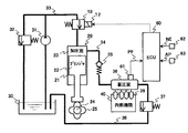
図1において、内燃機関の高圧燃料ポンプ制御装置は、燃料供給系統として、ソレノイド12を有する常開式の流量制御弁10と、シリンダ21、プランジャ22および加圧室23を有する高圧燃料ポンプ20と、ポンプカム25を有するカム軸24と、燃料が充填された燃料タンク30と、低圧燃料ポンプ31および低圧レギュレータ32を介して燃料タンク30に接続された低圧通路33と、高圧燃料ポンプ20の加圧室23に接続された高圧通路(吐出通路)34と、吐出弁(逆止弁)35を介して高圧通路34に接続された蓄圧室36と、リリーフ弁37を介して蓄圧室36と燃料タンク30との間を接続するリリーフ通路38と、蓄圧室36内に蓄積された燃料を内燃機関40の各燃焼室に噴射供給する燃料噴射弁39とを備えている。
In FIG. 1, a high-pressure fuel pump control device for an internal combustion engine includes a normally-open
また、高圧燃料ポンプ制御装置は、制御系統として、電磁弁からなる流量制御弁10のソレノイド12の励磁(流量制御弁10の閉弁)駆動タイミングを制御するECU60を備えている。
ECU60は、後述するように、目標圧力設定手段、フィードバック量演算手段、流量制御弁制御手段、フィードバック状態判定手段、積分演算更新禁止手段および燃料噴射量演算手段などを含む。また、ECU60には、燃圧センサ61、クランク角センサ62、アクセルポジションセンサ63などの各種センサからの検出信号が内燃機関40の運転情報として入力されている。
Further, the high-pressure fuel pump control device includes an
As will be described later, the
低圧燃料ポンプ31は、燃料タンク30内の燃料を汲み上げて低圧通路33に吐出し、高圧燃料ポンプ20は、低圧燃料ポンプ31から吐出された燃料を加圧室23内に吸入して吐出する。
低圧通路33は、流量制御弁10を介して高圧燃料ポンプ20内の加圧室23の上流側に接続されている。すなわち、流量制御弁10は、低圧通路33と加圧室23とを接続する燃料通路中に配置されている。
吐出弁35は、加圧室23と蓄圧室36とを接続する高圧通路34中に配置されている。
The low-
The
The
燃料噴射弁39は、蓄圧室36内の高圧燃料を、内燃機関40の気筒ごとの各燃焼室内に直接噴射して供給する。
燃圧センサ61は、蓄圧室36内の燃圧PFを検出してECU60に出力する。
The
The
燃料供給系統の低圧通路33側において、低圧燃料ポンプ31から吐出された燃料は、低圧レギュレータ32により所定の低圧値に調整されており、プランジャ22がシリンダ21内で下動する際に、流量制御弁10を通して加圧室23内に導入される。
On the
高圧燃料ポンプ20内のプランジャ22は、内燃機関40の回転に同期してシリンダ21内で往復動作する。これにより、高圧燃料ポンプ20は、プランジャ22の下動期間中においては低圧通路33から流量制御弁10を介して加圧室23内に燃料を吸入し、プランジャ22の上動期間中においては流量制御弁10の閉弁駆動中に加圧室23内の燃料を高圧に加圧し、吐出弁35を介して蓄圧室36に供給する。
The
加圧室23は、シリンダ21の内周壁面とプランジャ22の上端面とにより区画形成されている。
プランジャ22の下端は、内燃機関40のカム軸24に設けられたポンプカム25に圧接され、カム軸24の回転に連動してポンプカム25が回転することにより、プランジャ22がシリンダ21内を往復動作して、加圧室23内の容積が拡大/縮小変化するようになっている。
The pressurizing
The lower end of the
加圧室23の下流側に接続された高圧通路34は、加圧室23から蓄圧室36に向かう燃料の流通のみを許す逆止弁からなる吐出弁35を介して、蓄圧室36に接続されている。
蓄圧室36は、加圧室23から吐出された高圧の燃料を蓄積保持するとともに、内燃機関40の各燃料噴射弁39に対して共通に接続されて、蓄積した高圧の燃料を燃料噴射弁39に分配する。
The high-
The
蓄圧室36に接続されたリリーフ弁37は、所定の燃圧(開弁圧設定値)以上で開弁する常閉弁からなり、蓄圧室36内の燃圧がリリーフ弁37の開弁圧設定値以上に上昇しようとしたときに開弁する。これにより、開弁圧設定値以上に上昇しようとした蓄圧室36内の燃料は、リリーフ通路38を通して燃料タンク30に戻され、蓄圧室36内の燃圧が過大になることはない。
The
低圧燃料ポンプ31と加圧室23とを接続する低圧通路33に設けられた流量制御弁10は、ECU60の制御下で閉弁(ソレノイド12の励磁)駆動タイミングが制御され、高圧燃料ポンプ20から蓄圧室36への燃料吐出量を調整する。
高圧燃料ポンプ20において、プランジャ22がシリンダ21内で上動(加圧室23の容積が縮小)する際に、流量制御弁10が開弁(ソレノイド12の消磁)制御されている間は、加圧室23に吸入されている燃料が、加圧室23から流量制御弁10を通じて低圧通路33に戻されるので、蓄圧室36に高圧燃料が供給されることはない。
The
In the high-
一方、プランジャ22がシリンダ21内で上動中の所定タイミングのときに流量制御弁10を閉弁した後は、加圧室23で加圧された燃料が吐出通路34に吐出され、吐出弁35を通して蓄圧室36に供給される。
On the other hand, after the flow
ECU60は、燃圧センサ61で検出される蓄圧室36内の燃圧PFと、クランク角センサ62で検出される内燃機関40の回転速度NEと、アクセルポジションセンサ63で検出されるアクセルペダル(図示せず)の踏込量APなどを、各種運転状態情報として取り込む。
The
ECU60は、クランク角センサ62で検出される回転速度NEとアクセルポジションセンサ63で検出されるアクセルペダル踏込量APとに基づいて目標圧力POを決定し、蓄圧室36内の燃圧PFを目標圧力POに一致させるために必要な目標燃料吐出量QOを演算し、目標燃料吐出量QOに応じて流量制御弁10の閉弁駆動(ソレノイド12の励磁駆動)タイミングTDを設定し、高圧燃料ポンプ20から畜圧室36に吐出される燃料量を制御する。
The
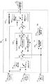
次に、図2の機能ブロック図を参照しながら、この発明に係るECU60の制御機能を実現するための具体的な構成について説明する。
なお、図2はECU60の機能構成を示しており、関連要素10、12、61〜63については、前述の図1と同一符号を付して詳述を省略する。
Next, a specific configuration for realizing the control function of the
2 shows the functional configuration of the
図2において、ECU60には、蓄圧室36内の燃圧PFを検出する燃圧センサ61と、内燃機関40の回転速度NEを検出するクランク角センサ62と、アクセルペダル踏込量APを検出するアクセルポジションセンサ63とが接続されている。
ECU60は、上記センサ手段61〜63を含む各種センサの検出情報に基づいて、流量制御弁10の閉弁(ソレノイド12の励磁)駆動タイミングを制御する。
In FIG. 2, the
The
ECU60は、目標圧力マップを含む目標圧力設定手段601と、フィードバック量演算手段602と、流量制御弁制御手段603と、積分演算更新禁止手段605とを備えている。
また、詳述を省略するが、ECU60は、内燃機関の制御手段としても機能しており、燃料噴射弁39から噴射される燃料噴射量QINJを演算する燃料噴射量演算手段604を備えているとともに、燃料噴射弁39や点火コイル(図示せず)などの各種アクチュエータを駆動制御する手段(図示せず)も備えている。
The
Although not described in detail, the
フィードバック量演算手段602は、目標圧力POと検出された燃圧PFとの圧力偏差ΔPFを算出する減算器621と、圧力偏差ΔPFを用いた比例演算部622および積分演算部623と、比例演算項QFBPおよび積分演算項QFBIを加算して燃料吐出フィードバック量QFBを算出する加算器624とを備えている。
流量制御弁制御手段603は、燃料吐出フィードバック量QFBおよび燃料噴射量QINJを加算して目標燃料吐出量QOを算出する加算器631と、回転速度NEおよび目標燃料吐出量QOを用いて駆動タイミングTDを設定する駆動タイミング設定手段632とを備えている。駆動タイミング設定手段632は、駆動タイミングマップを含む。
The feedback amount calculation means 602 includes a
The flow control valve control means 603 adds the fuel discharge feedback amount QFB and the fuel injection amount QINJ to calculate the target fuel discharge amount QO, and the drive timing TD using the rotational speed NE and the target fuel discharge amount QO. Drive timing setting means 632 for setting. The drive timing setting means 632 includes a drive timing map.
ECU60において、目標圧力設定手段601には、クランク角センサ62で検出される内燃機関40の回転速度NEと、アクセルポジションセンサ63で検出されるアクセルペダル踏込量APとが入力される。
目標圧力設定手段601は、回転速度NEおよびアクセルペダル踏込量APに基づく目標圧力マップ演算により、畜圧室36内の目標圧力POを設定してフィードバック量演算手段602に入力する。
In the
The target pressure setting means 601 sets the target pressure PO in the
フィードバック量演算手段602内の減算器621は、目標圧力POと燃圧センサ61で検出された畜圧室36内の燃圧PFとを入力情報として、目標圧力POと燃圧PFとの圧力偏差△PF(=PO−PF)を演算し、比例演算部622および積分演算部623に入力する。
A
比例演算部622および積分演算部623は、圧力偏差△PFに基づく比例演算および積分演算を実行し、比例演算項QFBPおよび積分演算項QFBIを算出する。
以下、加算器624は、比例演算項QFBPと積分演算項QFBIとを加算し、高圧燃料ポンプ20の燃料吐出フィードバック量QFB(=QFBP+QFBI)を算出して、流量制御弁制御手段603内の加算器631に入力する。
一方、燃料噴射量演算手段604は、燃料噴射弁39から噴射される燃料噴射量QINJを演算して、流量制御弁制御手段603内の加算器631に入力する。
Proportional calculation unit 622 and
Hereinafter, the
On the other hand, the fuel injection amount calculation means 604 calculates the fuel injection amount QINJ injected from the
なお、フィードバック量演算手段602内の比例演算部622で算出される比例演算項QFBPは、圧力偏差△PFに基づいて、たとえば以下の式(1)のように演算される。 The proportional calculation term QFBP calculated by the proportional calculation unit 622 in the feedback amount calculation means 602 is calculated, for example, as in the following equation (1) based on the pressure deviation ΔPF.
QFBP=△PF×KP ・・・(1) QFBP = ΔPF × KP (1)
ただし、式(1)において、KPは比例係数である。
すなわち、比例演算項QFBPは、PO>PF(圧力偏差△PFの符号が「+(プラス)」)の場合には、圧力偏差△PFに比例した正の値となり、反対に、PO<PF(圧力偏差△PFの符号が「−(マイナス)」)の場合には、圧力偏差△PFに比例した負の値となる。
However, in Equation (1), KP is a proportional coefficient.
That is, the proportional calculation term QFBP is a positive value proportional to the pressure deviation ΔPF when PO> PF (the sign of the pressure deviation ΔPF is “+ (plus)”), and on the contrary, PO <PF ( When the sign of the pressure deviation ΔPF is “− (minus)”), the pressure deviation ΔPF is a negative value proportional to the pressure deviation ΔPF.
また、フィードバック量演算手段602内の積分演算部623で算出される積分演算項QFBIは、圧力偏差△PFの符号の向き(「+」または「−」)に応じて、たとえば、以下の式(2)、式(3)のいずれか一方の式が選択されて演算される。
In addition, the integral calculation term QFBI calculated by the
△PF≧0(符号が「+」)のとき、
QFBI=QFBI(前回値)+KI ・・・(2)
△PF<0(符号が「−」)のとき、
QFBI=QFBI(前回値)−KI ・・・(3)
ΔPF ≧ 0 (sign is “+”)
QFBI = QFBI (previous value) + KI (2)
ΔPF <0 (sign is “−”)
QFBI = QFBI (previous value) −KI (3)
ただし、式(2)、式(3)において、KIは積分係数である。
すなわち、積分演算項QFBIは、PO≧PF(圧力偏差△PFの符号が「+」または△PF=0)の場合には、式(2)により積分係数KIだけ大きな値となり、反対に、PO<PF(圧力偏差△PFの符号が「−」)の場合には、式(3)により積分係数KIだけ小さな値となる。
However, in Expressions (2) and (3), KI is an integration coefficient.
That is, the integral calculation term QFBI is a value that is larger by the integral coefficient KI according to the equation (2) when PO ≧ PF (the sign of the pressure deviation ΔPF is “+” or ΔPF = 0). When PF (the sign of the pressure deviation ΔPF is “−”), the value is reduced by the integral coefficient KI according to the equation (3).
また、フィードバック量演算手段602内の減算器621で演算される圧力偏差△PFは、積分演算更新禁止手段605へも出力される。
さらに、フィードバック量演算手段602内の積分演算部623は、積分演算更新禁止手段605から積分演算項QFBIの更新禁止要求があったとき、すなわち、積分演算更新禁止フラグFS=1が入力されたときには、積分演算項QFBIの更新を禁止して積分演算項QFBIの前回値を保持する機能も備えている。
Further, the pressure deviation ΔPF calculated by the
Further, the
流量制御弁制御手段603において、加算器631は、燃料吐出フィードバック量QFBと、燃料噴射量演算手段604で演算された燃料噴射量QINJとを加算し、目標燃料吐出量QO(=QFB+QINJ)を算出して流量制御弁制御手段603に入力する。
流量制御弁制御手段603は、目標燃料吐出量QOおよび回転速度NEを入力情報として、駆動タイミングマップに基づき流量制御弁10の駆動タイミング(ソレノイド12の励磁タイミング)TDを決定し、駆動タイミングTDを流量制御弁10(ソレノイド12)に出力する。
In the flow control valve control means 603, the
The flow control valve control means 603 determines the drive timing (excitation timing of the solenoid 12) TD of the
流量制御弁10においては、流量制御弁制御手段603にて決定された駆動タイミングTDで流量制御弁10が閉弁駆動されるようにソレノイド12が通電される。
この結果、前述のように、目標燃料吐出量QOに相当する燃料が高圧燃料ポンプ20から畜圧室36内に供給され、畜圧室36内の燃圧PFは、目標圧力POと一致するように制御される。
In the
As a result, as described above, fuel corresponding to the target fuel discharge amount QO is supplied from the high-
次に、この発明の実施の形態1の特徴部である積分演算更新禁止手段605の機能動作について具体的に説明する。
なお、積分演算更新禁止手段605の演算処理は、フィードバック量演算手段602と同一の制御周期で実行されるものとする。
Next, the functional operation of the integral calculation update prohibiting means 605 which is a characteristic part of
Note that the calculation process of the integral calculation
積分演算更新禁止手段605は、フィードバック量演算手段602から入力された圧力偏差△PFの符号が反転しないまま演算処理回数が第1の所定回数に達したときに、積分演算更新禁止フラグFSを「1」にセットし、FS=1にセットされた以降に、圧力偏差△PFの符号が反転したことが検出された時点で、積分演算更新禁止フラグFSを「0」にリセットする。 The integral calculation update prohibiting means 605 sets the integral calculation update prohibition flag FS when the number of calculation processes reaches the first predetermined number without inverting the sign of the pressure deviation ΔPF input from the feedback amount calculating means 602. The integral calculation update prohibition flag FS is reset to “0” when it is detected that the sign of the pressure deviation ΔPF has been reversed since FS = 1.
なお、図2内の破線矢印で示すように、積分演算更新禁止手段605には、燃圧PFの検出値も入力され得る(後述する実施の形態3参照)。
積分演算更新禁止フラグFSは、フィードバック量演算手段602内の積分演算部623に入力されており、FS=1に保持されている期間にわたって、積分演算項QFBIの更新を禁止して、積分演算項QFBIの前回値を保持するようになっている。
Note that, as indicated by a broken-line arrow in FIG. 2, the detected value of the fuel pressure PF can also be input to the integral calculation update prohibiting means 605 (see Embodiment 3 described later).
The integral calculation update prohibition flag FS is input to the
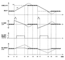
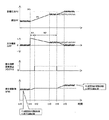
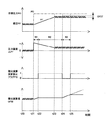
以下、図1および図2とともに、図3のタイミングチャートを参照しながら、積分演算更新禁止手段605から積分演算項623への更新禁止フラグFSの設定動作および積分演算部623による制御動作について説明する。
図3において、横軸は時間の経過を示しており、各制御動作の要所となる時刻位置のみに対してt0〜t10の符号が付されている。
また、時刻t1〜t2、時刻t6〜t7で示す期間N1は、燃料吐出フィードバック量QFBの演算が第1の所定回数K1だけ実行されるのに要する時間を示している。
Hereinafter, the setting operation of the update prohibition flag FS from the integral calculation update prohibiting means 605 to the
In FIG. 3, the horizontal axis indicates the passage of time, and only the time positions that are the main points of each control operation are denoted by the symbols t0 to t10.
Further, a period N1 indicated by the times t1 to t2 and the times t6 to t7 indicates the time required for the calculation of the fuel discharge feedback amount QFB to be executed for the first predetermined number of times K1.
また、図3内の縦軸は、上から順番に、目標圧力PO(2点鎖線)および燃圧PF(実線)、圧力偏差△PF(=PO−PF)、積分演算更新禁止フラグFS、積分演算項QFBIの各制御状態を示している。
さらに、図3内の燃圧PF、圧力偏差△PFおよび積分演算項QFBIに関して、この発明の実施の形態1が適用されたときの各動作は実線で示されており、この発明の実施の形態1が適用されなかったときの各動作は点線で示されている。
Also, the vertical axis in FIG. 3 indicates the target pressure PO (two-dot chain line) and fuel pressure PF (solid line), pressure deviation ΔPF (= PO-PF), integral calculation update prohibition flag FS, integral calculation in order from the top. Each control state of the term QFBI is shown.
Further, regarding the fuel pressure PF, the pressure deviation ΔPF, and the integral calculation term QFBI in FIG. 3, each operation when the first embodiment of the present invention is applied is shown by a solid line, and the first embodiment of the present invention is shown in FIG. Each operation when is not applied is indicated by a dotted line.
まず、図3内の時刻t0〜t1の期間においては、燃圧PFが目標圧力POとほぼ一致した状態で適正にフィードバック制御されているので、圧力偏差△PF(=PO−PF)の符号も、フィードバック制御に同期して「+」と「−」との反転を繰り返している。 First, during the period of time t0 to t1 in FIG. 3, since the fuel pressure PF is appropriately feedback controlled in a state where it substantially coincides with the target pressure PO, the sign of the pressure deviation ΔPF (= PO−PF) is Inversion of “+” and “−” is repeated in synchronization with the feedback control.
すなわち、積分演算項QFBIは、圧力偏差△PFの符号の反転に同期して、前述の式(2)、式(3)が逐次切替えられて演算されており、この状態においては、圧力偏差△PFの符号が反転しないまま燃料吐出フィードバック量QFBの演算回数が第1の所定回数K1に達することはない。
したがって、時刻t0〜t1の期間に積分演算更新禁止フラグFSが「1」にセットされることはない。
That is, the integral calculation term QFBI is calculated by sequentially switching the above equations (2) and (3) in synchronization with the inversion of the sign of the pressure deviation ΔPF. The number of times of calculation of the fuel discharge feedback amount QFB does not reach the first predetermined number K1 without inverting the sign of PF.
Therefore, the integral calculation update prohibition flag FS is not set to “1” during the period of time t0 to t1.
ところが、時刻t1においては、目標圧力POが大きな値に変更されたことによって、変更された目標圧力POと検出された燃圧PFとの間に「+符号」の大きな圧力偏差△PFが発生する。このため、時刻t1の直後では、圧力偏差△PFが「+符号」を示す状態がしばらく継続する。 However, at time t1, since the target pressure PO is changed to a large value, a large pressure deviation ΔPF of “+ sign” is generated between the changed target pressure PO and the detected fuel pressure PF. For this reason, immediately after time t1, the state in which the pressure deviation ΔPF indicates “+ sign” continues for a while.
このとき、仮に、この発明の実施の形態1が適用されなかった場合には、燃圧PFが上昇して目標圧力POに達するまでの間(すなわち、圧力偏差△PFが「−符号」に転じるまでの間)、積分演算部623による積分演算項QFBIの演算処理として、前述の式(2)が選択され続ける。
したがって、時刻t1〜t3までの期間にわたって、積分演算項QFBIは、図3内の点線で示したように、過度の増加を続ける。また、燃圧PFが上昇して目標圧力POに達した後(すなわち、圧力偏差△PFが「0」を下回って「−符号」に転じた後)において、燃圧PFは、目標圧力POを上回って、オーバーシュートを開始する(時刻t3の直後の点線参照)。
At this time, if the first embodiment of the present invention is not applied, the fuel pressure PF increases until it reaches the target pressure PO (that is, until the pressure deviation ΔPF turns to “−”). In the meantime, the above-described equation (2) is continuously selected as the calculation process of the integral calculation term QFBI by the
Therefore, over the period from time t1 to time t3, the integral calculation term QFBI continues to increase excessively as shown by the dotted line in FIG. Further, after the fuel pressure PF increases and reaches the target pressure PO (that is, after the pressure deviation ΔPF falls below “0” and changes to “−”), the fuel pressure PF exceeds the target pressure PO. Then, overshoot is started (see the dotted line immediately after time t3).
このようなオーバーシュートの発生中(図3内の点線参照)では、燃圧PFが目標圧力POよりも高くなっているので、圧力偏差△PF(=PO−PF)が「−符号」となり、積分演算項QFBIの演算処理は、前述の式(3)が選択され続ける。
したがって、積分演算項QFBIは、減少しながら、時刻t5において、ようやく正しい値に戻り着くようになる(時刻t3〜t5の期間内の点線で示す燃圧PF、圧力偏差△PF、積分演算項QFBIの動作参照)。
During the occurrence of such an overshoot (see the dotted line in FIG. 3), since the fuel pressure PF is higher than the target pressure PO, the pressure deviation ΔPF (= PO−PF) becomes “−sign” and integration is performed. In the calculation process of the calculation term QFBI, the above-described equation (3) is continuously selected.
Accordingly, the integral calculation term QFBI decreases and finally returns to the correct value at time t5 (the fuel pressure PF, the pressure deviation ΔPF indicated by the dotted line within the period from time t3 to t5, the integral calculation term QFBI). See operation).
一方、この発明の実施の形態1が適用された場合には、目標圧力POが大きな値に変更された時刻t1の直後では、前述と同様に、圧力偏差△PFが「+符号」となって、積分演算項QFBIの演算処理として前述の式(2)が選択されることから、積分演算項QFBIが増加を開始するものの、圧力偏差△PFの符号が「+符号」から「−符号」に反転しないまま、燃料吐出フィードバック量QFBの演算回数が第1の所定回数K1に達した(時間に換算して、期間N1が経過した)ことが判定された時点(時刻t2)で、積分演算更新禁止フラグFSが「1」にセットされるので、積分演算項QFBIの更新が禁止される。 On the other hand, when the first embodiment of the present invention is applied, immediately after time t1 when the target pressure PO is changed to a large value, the pressure deviation ΔPF becomes “+ sign” as described above. Since the above equation (2) is selected as the calculation process of the integral calculation term QFBI, the integral calculation term QFBI starts to increase, but the sign of the pressure deviation ΔPF is changed from “+ sign” to “− sign”. The integral calculation update is performed at a time (time t2) when it is determined that the number of times of calculation of the fuel discharge feedback amount QFB has reached the first predetermined number K1 (time period N1 has elapsed in terms of time) without being reversed. Since the prohibition flag FS is set to “1”, the update of the integral calculation term QFBI is prohibited.
この結果、積分演算項QFBIの更新が禁止された時点から、燃圧PFが上昇して目標圧力POに達するまでの間(すなわち、圧力偏差△PFが「−符号」に転じるまでの間)にわたって、積分演算項QFBIの更新が禁止されて、時刻t2の時点での値が保持される(時刻t2〜t3の期間内の実線で示す燃圧PF、圧力偏差△PFおよび積分演算項QFBIの動作参照)。 As a result, from when the update of the integral calculation term QFBI is prohibited until the fuel pressure PF increases and reaches the target pressure PO (that is, until the pressure deviation ΔPF turns to “−sign”), The update of the integral calculation term QFBI is prohibited and the value at the time t2 is held (see the operation of the fuel pressure PF, the pressure deviation ΔPF and the integral calculation term QFBI indicated by the solid line in the period from the time t2 to the time t3). .
続いて、圧力偏差△PFが「0」を下回って「−符号」に転じた時点(時刻t3)で、積分演算更新禁止フラグFSが「0」にリセットされることにより、積分演算項QFBIの更新が再開されることになる。
したがって、積分演算項QFBIが過度に大きくなることが無くなるので、燃圧PFが上昇して目標圧力POに達した後に大きなオーバーシュートが発生することもなく、積分演算項QFBIが速やかに適正値に戻り着くようになる(時刻t3〜t4の期間内の実線で示す燃圧PF、圧力偏差△PFおよび積分演算項QFBIの動作参照)。
Subsequently, when the pressure deviation ΔPF falls below “0” and changes to “− sign” (time t3), the integral calculation update prohibition flag FS is reset to “0”, so that the integral calculation term QFBI Updates will be resumed.
Therefore, since the integral calculation term QFBI does not become excessively large, a large overshoot does not occur after the fuel pressure PF increases to reach the target pressure PO, and the integral calculation term QFBI quickly returns to an appropriate value. (Refer to the operation of the fuel pressure PF, the pressure deviation ΔPF, and the integral calculation term QFBI indicated by the solid line in the period from the time t3 to the time t4).
続いて、図3内の時刻t5〜t6の期間においては、前述の時刻t0〜t1の期間と同様に、燃圧PFが目標圧力POとほぼ一致した状態で、適正にフィードバック制御されているので、圧力偏差△PF(=PO−PF)の符号も、フィードバック制御に同期して「+」および「−」の反転を繰り返している。 Subsequently, in the period from time t5 to t6 in FIG. 3, as in the period from time t0 to t1, the fuel pressure PF is appropriately feedback controlled in a state where the fuel pressure PF substantially matches the target pressure PO. The sign of the pressure deviation ΔPF (= PO−PF) also repeats the inversion of “+” and “−” in synchronization with the feedback control.
すなわち、積分演算項QFBIは、圧力偏差△PFの符号の反転に同期して、前述の式(2)、式(3)が逐次切替えられて演算されており、この状態においては、圧力偏差△PFの符号が反転しないまま、燃料吐出フィードバック量QFBの演算回数が第1の所定回数K1に達することはない。
したがって、時刻t5〜t6の期間に積分演算更新禁止フラグFSが「1」にセットされることはない。
That is, the integral calculation term QFBI is calculated by sequentially switching the above equations (2) and (3) in synchronization with the inversion of the sign of the pressure deviation ΔPF. The number of calculations of the fuel discharge feedback amount QFB does not reach the first predetermined number K1 without the sign of PF being inverted.
Therefore, the integral calculation update prohibition flag FS is not set to “1” during the period from time t5 to t6.
ところが、時刻t6の時点では、目標圧力POが小さな値に変更されたことによって、変更された目標圧力POと燃圧PFとの間に「−符号」の大きな圧力偏差△PFが発生する。
したがって、時刻t6の直後においては、圧力偏差△PFが「−符号」を示す状態がしばらく継続する。
However, at time t6, since the target pressure PO is changed to a small value, a large pressure deviation ΔPF with a “− sign” occurs between the changed target pressure PO and the fuel pressure PF.
Therefore, immediately after time t6, the state where the pressure deviation ΔPF indicates “− sign” continues for a while.
ここで、仮に、この発明の実施の形態1を適用しなかった場合には、燃圧PFが下降して目標圧力POに達するまで(時刻t6〜t8)の期間(すなわち、圧力偏差△PFが「+符号」に転じるまでの期間)にわたって、積分演算項QFBIの演算処理として前述の式(3)が選択され続けるので、図3内の点線で示すように、積分演算項QFBIは過度の減少を続ける。そして、燃圧PFが下降して目標圧力POに達した後(すなわち、圧力偏差△PFが「0」を上回って「+符号」に転じた後)には、燃圧PFが目標圧力POを下回ってアンダーシュートを開始する(時刻t8の直後の点線で示す燃圧PFを参照)。 Here, if the first embodiment of the present invention is not applied, the period (that is, the pressure deviation ΔPF) until the fuel pressure PF decreases and reaches the target pressure PO (time t6 to t8) is “ Since the above equation (3) continues to be selected as the calculation process of the integral calculation term QFBI over the period until it changes to “+ sign”, the integral calculation term QFBI does not decrease excessively as shown by the dotted line in FIG. to continue. After the fuel pressure PF decreases and reaches the target pressure PO (that is, after the pressure deviation ΔPF exceeds “0” and turns to “+”), the fuel pressure PF falls below the target pressure PO. Undershoot is started (see fuel pressure PF indicated by a dotted line immediately after time t8).
このとき、時刻t8の直後のアンダーシュートの発生中は、燃圧PFが目標圧力POよりも低くなっていることから、圧力偏差△PFが「+符号」となり、積分演算項QFBIの演算処理として前述の式(2)が選択され続けるので、積分演算項QFBIは、増加しながら、時刻t10の時点でようやく正しい値に戻り着くようになる(時刻t8〜t10の期間内の点線で示した燃圧PF、圧力偏差△PF、積分演算項QFBIの動作参照)。 At this time, during the occurrence of undershoot immediately after time t8, since the fuel pressure PF is lower than the target pressure PO, the pressure deviation ΔPF becomes “+ sign”, and the calculation processing of the integral calculation term QFBI is described above. Therefore, the integral calculation term QFBI increases and finally returns to the correct value at time t10 (the fuel pressure PF indicated by the dotted line within the period from time t8 to t10). , Pressure deviation ΔPF, operation of integral calculation term QFBI).
一方、この発明の実施の形態1を適用した場合には、目標圧力POが小さな値に変更された時刻t6の直後では、圧力偏差△PFが「−符号」となって、積分演算項QFBIの演算処理として前述の式(3)が選択されることから、積分演算項QFBIが減少を開始するものの、圧力偏差△PFの符号が「−符号」から「+符号」に反転しないまま燃料吐出フィードバック量QFBの演算回数が第1の所定回数K1に達した(時間に換算して、期間N1が経過した)ことが判定された時点(時刻t7)で、積分演算更新禁止フラグFSが「1」にセットされるので、QFBIの更新が禁止される。 On the other hand, when the first embodiment of the present invention is applied, immediately after time t6 when the target pressure PO is changed to a small value, the pressure deviation ΔPF becomes “−sign” and the integral calculation term QFBI is Since the above-described equation (3) is selected as the calculation process, the integral calculation term QFBI starts to decrease, but the fuel discharge feedback without changing the sign of the pressure deviation ΔPF from “− sign” to “+ sign”. At the time (time t7) when it is determined that the number of computations of the quantity QFB has reached the first predetermined number of times K1 (time N7 has elapsed in terms of time), the integral computation update prohibition flag FS is “1”. Therefore, QFBI update is prohibited.
この結果、積分演算項QFBIの更新が禁止された時点(時刻t6)から燃圧PFが下降して目標圧力POに達するまでの時刻t7〜t8の期間(すなわち、圧力偏差△PFが「+符号」に転じるまでの期間)にわたって、積分演算項QFBIの更新が禁止され積分演算項QFBIは、時刻t7の時点の値に保持される(図3内の実線で示した燃圧PF、圧力偏差△PF、積分演算項QFBIの動作参照)。 As a result, the period from time t7 to t8 from when the update of the integral calculation term QFBI is prohibited (time t6) to when the fuel pressure PF decreases and reaches the target pressure PO (that is, the pressure deviation ΔPF is “+ sign”). Update of the integral calculation term QFBI is prohibited over the period until the shift to), and the integral calculation term QFBI is held at the value at the time t7 (the fuel pressure PF, the pressure deviation ΔPF shown by the solid line in FIG. (Refer to the operation of the integral operation term QFBI).
続いて、圧力偏差△PFが「0」を上回って「+符号」に転じた時点(時刻t8)で、積分演算更新禁止フラグFSが「0」にリセットされることにより、積分演算項QFBIの更新が再開されることになる。
このように、この発明の実施の形態1を適用した場合には、積分演算項QFBIが過度に小さくなることが無くなり、燃圧PFが下降して目標圧力POに達した時刻t8の後に大きなアンダーシュートが発生することもなく、積分演算項QFBIが速やかに適正値に戻り着くようになる(時刻t8〜t9の期間内の実線で示した燃圧PF、圧力偏差△PF、積分演算項QFBIの動作参照)。
Subsequently, when the pressure deviation ΔPF exceeds “0” and changes to “+ sign” (time t8), the integral calculation update prohibition flag FS is reset to “0”, so that the integral calculation term QFBI Updates will be resumed.
As described above, when the first embodiment of the present invention is applied, the integral calculation term QFBI is not excessively decreased, and a large undershoot occurs after time t8 when the fuel pressure PF decreases and reaches the target pressure PO. Without being generated, the integral calculation term QFBI quickly returns to an appropriate value (see the operation of the fuel pressure PF, the pressure deviation ΔPF, and the integral calculation term QFBI indicated by solid lines in the period from time t8 to t9). ).
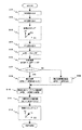
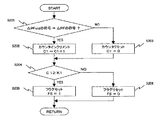
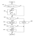
次に、図4のフローチャートを参照しながら、図2に示したこの発明の実施の形態1によるECU60の基本的な制御動作について説明する。
まず、図4において、ECU60は、クランク角センサ62で検出された回転速度NEを読み込むとともに(ステップS101)、アクセルポジションセンサ63で検出されたアクセルペダル踏込量APを読み込み(ステップS102)、目標圧力設定手段(目標圧力マップ)601により、回転速度NEおよびアクセルペダル踏込量APに応じた目標圧力POを決定する(ステップS103)。
Next, a basic control operation of
First, in FIG. 4, the
続いて、燃圧センサ61で検出された畜圧室36内の燃圧PFを読み込み(ステップS104)、フィードバック量演算手段602内の減算器621により、圧力偏差△PF(=PO−PF)を演算する(ステップS105)。
また、圧力偏差ΔPFに基づいて、比例演算部622により、前述の式(1)を用いた比例演算を行い、比例演算項QFBPを演算する(ステップS106)。
Subsequently, the fuel pressure PF in the
Further, based on the pressure deviation ΔPF, the proportional calculation unit 622 performs a proportional calculation using the above-described equation (1) to calculate the proportional calculation term QFBP (step S106).
続いて、積分演算更新禁止フラグFSが「0」(リセット)の状態であるか否かを判定する(ステップS107)。なお、積分演算更新禁止フラグFSの具体的な設定処理については後述する(図5参照)。
ステップS107において、FS=0(すなわち、YES)と判定されれば、圧力偏差ΔPFに基づいて、前述の式(2)または式(3)を用いた積分演算を行い、積分演算項QFBIを更新する(ステップS108)。
一方、ステップS107において、FS=1(すなわち、NO)と判定されれば、積分演算項QFBIの更新を禁止し、今回の積分演算項QFBIの値を前回の積分演算項QFBIoldの値に保持(QFBI=QFBIold)する(ステップS109)。
Subsequently, it is determined whether or not the integral calculation update prohibition flag FS is in a state of “0” (reset) (step S107). A specific setting process of the integral calculation update prohibition flag FS will be described later (see FIG. 5).
If it is determined in step S107 that FS = 0 (that is, YES), based on the pressure deviation ΔPF, the integral calculation using the above-described equation (2) or (3) is performed, and the integral calculation term QFBI is updated. (Step S108).
On the other hand, if it is determined in step S107 that FS = 1 (that is, NO), updating of the integral calculation term QFBI is prohibited, and the value of the current integral calculation term QFBI is held at the value of the previous integral calculation term QFBIold ( QFBI = QFBIold) (step S109).
次に、加算器624により、比例演算項QFBPと積分演算項QFBIとを加算して、燃料吐出フィードバック量QFB(=QFBP+QFBI)を演算し(ステップS110)、流量制御弁制御手段603内の加算器631により、燃料吐出フィードバック量QFBと燃料噴射量QINJとを加算して、目標燃料吐出量QO(=QFB+QINJ)を演算する(ステップS111)。
Next, the
続いて、目標燃料吐出量QOおよび回転速度NEに基づき、駆動タイミング設定手段632により、駆動タイミングマップを用いて流量制御弁10の駆動タイミングTDを設定し(ステップS112)、図4の処理ルーチンを抜け出る。
以下、流量制御弁10においては、駆動タイミングTDによって閉弁駆動されるようにソレノイド12が通電制御される。
Subsequently, based on the target fuel discharge amount QO and the rotational speed NE, the drive timing setting means 632 sets the drive timing TD of the
Hereinafter, in the
次に、図5のフローチャートを参照しながら、ECU60内の積分演算更新禁止手段605による積分演算更新禁止フラグFS(判定ステップS107で用いられる)の設定処理について、具体的に説明する。
なお、積分演算更新禁止手段605は、圧力偏差△PFの符号が反転しない状態の継続時間(演算回数K1に対応)を計測するためのカウンタC1を有している。
Next, the setting process of the integral calculation update prohibition flag FS (used in determination step S107) by the integral calculation update prohibiting means 605 in the
The integral calculation update prohibiting means 605 has a counter C1 for measuring the duration (corresponding to the calculation count K1) in which the sign of the pressure deviation ΔPF is not reversed.
図5において、積分演算更新禁止手段605は、まず、図4内のステップS105で演算された圧力偏差△PFの符号が、前回演算実行時に演算された圧力偏差前回値△PFoldの符号に対して同一(ΔPFoldの符号=ΔPF)であったか否か(反転したか)を判定する(ステップS201)。 In FIG. 5, the integral calculation update prohibiting means 605 first determines that the sign of the pressure deviation ΔPF calculated in step S105 in FIG. 4 is the same as the sign of the pressure deviation previous value ΔPFold calculated during the previous calculation. It is determined whether or not they are the same (sign of ΔPFold = ΔPF) (inverted) (step S201).
ステップS201において、「△PFoldの符号=△PFの符号」(すなわち、YES)と判定されれば、圧力偏差△PFの符号が反転していないので、カウンタC1の値をC1=C1+1にインクリメントする(ステップS202)。
一方、ステップS201において、「△PFoldの符号≠△PFの符号」(すなわち、NO)と判定されれば、圧力偏差△PFの符号が反転しているので、カウンタC1の値をC1=0にリセットする(ステップS203)。
If it is determined in step S201 that “sign of ΔPFold = sign of ΔPF” (ie, YES), the sign of the pressure deviation ΔPF is not inverted, so the value of the counter C1 is incremented to C1 = C1 + 1. (Step S202).
On the other hand, if it is determined in step S201 that “sign of ΔPFold ≠ sign of ΔPF” (that is, NO), the sign of the pressure deviation ΔPF is inverted, so the value of the counter C1 is set to C1 = 0. Reset (step S203).
続いて、カウンタC1が所定値K1に達したか否かを判定し(ステップS204)、C1≧K1(すなわち、YES)と判定されれば、図3内の所定期間N1が経過したので、FS=1にセットして(ステップS205)、図5の処理ルーチンを抜け出る。
一方、ステップS204において、C1<K1(すなわち、NO)と判定されれば、FS=0にリセットして(ステップS206)、図5の処理ルーチンを抜け出る。
Subsequently, it is determined whether or not the counter C1 has reached the predetermined value K1 (step S204). If it is determined that C1 ≧ K1 (that is, YES), the predetermined period N1 in FIG. = 1 is set (step S205), and the processing routine of FIG. 5 is exited.
On the other hand, if it is determined in step S204 that C1 <K1 (that is, NO), FS is reset to 0 (step S206), and the process routine of FIG. 5 is exited.
以下、積分演算更新禁止フラグFSは、フィードバック量演算手段602に入力され、積分演算部623においては、積分演算更新禁止フラグFSの状態の判定処理(図4内のステップS107)が実行される。
すなわち、FS=0の場合には、積分演算項QFBIが更新され(ステップS108)、FS=1の場合には、積分演算項QFBIの更新が禁止され(ステップS109)、これに続いて、前述のステップS110〜S112の処理が実行される。
Hereinafter, the integral calculation update prohibition flag FS is input to the feedback amount calculation means 602, and the
That is, when FS = 0, the integral calculation term QFBI is updated (step S108), and when FS = 1, the update of the integral calculation term QFBI is prohibited (step S109). Steps S110 to S112 are executed.
以上のように、この発明の実施の形態1に係る内燃機関の高圧燃料ポンプ制御装置は、内燃機関40の運転状態を検出する各種センサ62、63と、吸入された低圧の燃料を加圧して吐出する高圧燃料ポンプ20と、駆動タイミングTDが設定されることにより高圧燃料ポンプ20から吐出される燃料量を調整する流量制御弁10と、高圧燃料ポンプ20から吐出された燃料を畜圧する畜圧室36と、畜圧室36内の燃料を内燃機関40の各燃焼室に噴射供給する燃料噴射弁39と、蓄圧室36内の燃圧PFを検出する燃圧センサ61と、運転状態に基づいて畜圧室36内の目標圧力POを設定する目標圧力設定手段601と、目標圧力POと燃圧センサ61で検出された燃圧PFとの圧力偏差ΔPFに基づく比例積分演算により高圧燃料ポンプ20の燃料吐出フィードバック量QFBを演算するフィードバック量演算手段602と、燃料噴射弁39から噴射される燃料噴射量QINJと燃料吐出フィードバック量QFBとを加算して求めた目標燃料吐出量QOに基づいて流量制御弁10の駆動タイミングTDを設定する流量制御弁制御手段603と、積分演算更新禁止手段605とを備えている。
As described above, the high-pressure fuel pump control apparatus for an internal combustion engine according to
積分演算更新禁止手段605は、圧力偏差ΔPFの符号が反転しないまま燃料吐出フィードバック量QFBの演算回数が第1の所定回数K1(期間N1に相当)に達したときに、燃料吐出フィードバック量QFBにおける積分演算項QFBIの更新を禁止し、その後に圧力偏差ΔPFの符号が反転したときに、積分演算項QFBIの更新を再開させるようになっている。
これにより、目標圧力POと畜圧室39内の燃圧PFとの圧力偏差ΔPFを「0」にするためのフィードバック制御時に、積分演算項QFBIが過大または過小になることや、不適切な値のまま更新が禁止されることにより、燃圧PFのオーバーシュートやアンダーシュートが発生することを確実に回避することが可能となり、内燃機関40の燃焼状態や排ガスの悪化を防止することができる。
The integral calculation update prohibiting means 605 performs the fuel discharge feedback amount QFB in the fuel discharge feedback amount QFB when the number of calculation of the fuel discharge feedback amount QFB reaches the first predetermined number K1 (corresponding to the period N1) without the sign of the pressure deviation ΔPF being inverted. Updating of the integral calculation term QFBI is prohibited, and when the sign of the pressure deviation ΔPF is reversed thereafter, the update of the integral calculation term QFBI is resumed.
As a result, the integral operation term QFBI is excessively large or small, or an inappropriate value is set during feedback control for setting the pressure deviation ΔPF between the target pressure PO and the fuel pressure PF in the
実施の形態2.
なお、上記実施の形態1では、圧力偏差ΔPFの符号が反転しないまま燃料吐出フィードバック量QFBの演算回数が第1の所定回数(所定期間N1)に達したときに、燃料吐出フィードバック量QFBにおける積分演算項QFBIの更新を禁止し、その後に圧力偏差ΔPFの符号が反転したときに、積分演算項QFBIの更新を再開したが、積分演算項QFBIの更新を禁止した時点から、圧力偏差ΔPFの符号が一度も反転しないまま燃料吐出フィードバック量QFBの演算回数が第2の所定回数(所定期間N2>N1)に達したときには、圧力偏差△PFの符号が反転しなくても積分演算項QFBIの更新を再開してもよい。
In the first embodiment, when the number of calculation of the fuel discharge feedback amount QFB reaches the first predetermined number (predetermined period N1) without the sign of the pressure deviation ΔPF being inverted, the integration in the fuel discharge feedback amount QFB is performed. When the update of the calculation term QFBI is prohibited and then the sign of the pressure deviation ΔPF is reversed, the update of the integral calculation term QFBI is resumed. However, since the update of the integral calculation term QFBI is prohibited, the sign of the pressure deviation ΔPF When the number of calculations of the fuel discharge feedback amount QFB reaches the second predetermined number (predetermined period N2> N1) without ever reversing, the integral calculation term QFBI is updated even if the sign of the pressure deviation ΔPF is not reversed. May be resumed.
以下、図1および図2とともに、図6〜図9を参照しながら、この発明の実施の形態2に係る内燃機関の高圧燃料ポンプ制御装置について説明する。
なお、この発明の実施の形態2の概略構成およびECU60の制御機能については、前述の図1および図2と同様なので、ここでは説明を省略し、この発明の実施の形態2を特徴付けるECU60内の積分演算更新禁止手段605に追加された機能動作のみに注目して説明する。
A high-pressure fuel pump control apparatus for an internal combustion engine according to
Note that the schematic configuration of the second embodiment of the present invention and the control function of the
この発明の実施の形態2による積分演算更新禁止手段605は、フィードバック量演算手段602から入力された圧力偏差△PFの符号が反転しないまま演算処理回数が第1の所定回数(所定期間N1)に達したことにより、積分演算更新禁止フラグがFS=1にセットされてQFBIの更新が禁止された時点から、圧力偏差△PFの符号が一度も反転しないままフィードバック量演算手段602の演算回数が第2の所定回数(所定期間N2)に達したときには、圧力偏差△PFの符号が反転していなくても、積分演算更新禁止フラグFSを「0」にリセットして、積分演算項QFBIの更新を再開させる。 The integral calculation update prohibiting means 605 according to the second embodiment of the present invention sets the number of calculation processes to the first predetermined number of times (predetermined period N1) without inverting the sign of the pressure deviation ΔPF input from the feedback amount calculating means 602. As a result, the integral calculation update prohibition flag is set to FS = 1 and the update of QFBI is prohibited, so that the number of calculations of the feedback amount calculation means 602 is performed with the sign of the pressure deviation ΔPF never reversed. When the predetermined number of times (predetermined period N2) is reached, even if the sign of the pressure deviation ΔPF is not inverted, the integral calculation update prohibition flag FS is reset to “0” and the integral calculation term QFBI is updated. Let it resume.
図6はこの発明の実施の形態2における積分演算更新禁止手段605による積分演算更新禁止フラグFSの設定動作および積分演算部623による制御動作を示すタイミングチャートである。
図6において、横軸は時間経過を示し、各制御動作の要所となる時刻位置のみに対してt10〜t15の符号が付されている。
FIG. 6 is a timing chart showing the setting operation of the integral calculation update prohibition flag FS by the integral calculation update prohibiting means 605 and the control operation by the
In FIG. 6, the horizontal axis indicates the passage of time, and only t10 to t15 are assigned to the time positions that are the main points of each control operation.
また、時刻t11〜t12で示す期間N1は、前述(図3参照)と同様に、燃料吐出フィードバック量QFBの演算が第1の所定回数K1だけ実行されるのに要する時間を示している。
一方、時刻t12〜t14で示す期間N2は、燃料吐出フィードバック量QFBの演算が第2の所定回数K2(>K1)だけ実行されるのに要する時間を示している。
なお、第2の所定回数K2は、後述するように、積分演算項QFBIの更新を禁止した時点(時刻t12)の圧力偏差ΔPFに応じた異なる値に設定される(図8参照)。
Also, the period N1 indicated by the times t11 to t12 indicates the time required for the calculation of the fuel discharge feedback amount QFB to be executed for the first predetermined number of times K1 as described above (see FIG. 3).
On the other hand, a period N2 indicated by times t12 to t14 indicates a time required for the calculation of the fuel discharge feedback amount QFB to be executed a second predetermined number of times K2 (> K1).
The second predetermined number of times K2 is set to a different value according to the pressure deviation ΔPF at the time (time t12) when the update of the integral calculation term QFBI is prohibited, as will be described later (see FIG. 8).
また、図6内の縦軸は、前述と同様に、上から順番に、目標圧力PO(2点鎖線)および燃圧PF(実線)、圧力偏差△PF(=PO−PF)、積分演算更新禁止フラグFS、積分演算項QFBIの各制御状態を示している。
さらに、図6内の燃圧PF、圧力偏差△PF、積分演算更新禁止フラグFSおよび積分演算項QFBIに関して、前述の実施の形態1のみを適用したとき(この発明の実施の形態2が適用されなかった場合)の各動作は点線で示され、前述の実施の形態1にこの発明の実施の形態2を追加適用したときの各動作は実線で示されている。
In addition, the vertical axis in FIG. 6 indicates the target pressure PO (two-dot chain line) and fuel pressure PF (solid line), pressure deviation ΔPF (= PO−PF), integral calculation update prohibition in order from the top, as described above. Each control state of the flag FS and the integral calculation term QFBI is shown.
Further, when only the above-described first embodiment is applied to the fuel pressure PF, pressure deviation ΔPF, integral calculation update prohibition flag FS and integral calculation term QFBI in FIG. 6 (the second embodiment of the present invention is not applied). The operations when the second embodiment of the present invention is additionally applied to the above-described first embodiment are indicated by solid lines.
図6において、まず、時刻t10〜t11の期間では、燃圧PFが目標圧力POとほぼ一致した状態で適正にフィードバック制御されているので、圧力偏差△PF(=PO−PF)の符号も、フィードバック制御に同期して「+」および「−」の反転を繰り返している。 In FIG. 6, first, during the period from time t10 to t11, the fuel pressure PF is appropriately feedback controlled in a state where the fuel pressure PF substantially coincides with the target pressure PO. Therefore, the sign of the pressure deviation ΔPF (= PO−PF) is also fed back. Inversion of “+” and “−” is repeated in synchronization with the control.
すなわち、積分演算項QFBIは、圧力偏差△PFの符号の反転に同期して、前述の式(2)、式(3)を逐次切替えられて演算されており、この状態においては、圧力偏差△PFの符号が反転しないまま燃料吐出フィードバック量QFBの演算回数が第1の所定回数K1に達することはない。
したがって、時刻t10〜t11の期間に積分演算更新禁止フラグFSが「1」にセットされることはない。
That is, the integral calculation term QFBI is calculated by sequentially switching the above equations (2) and (3) in synchronization with the inversion of the sign of the pressure deviation ΔPF. In this state, the pressure deviation Δ The number of times of calculation of the fuel discharge feedback amount QFB does not reach the first predetermined number K1 without inverting the sign of PF.
Therefore, the integral calculation update prohibition flag FS is not set to “1” during the period of time t10 to t11.
また、前述(図3内の時刻t1)と同様に、時刻t11の時点では、目標圧力POが大きな値に変更されたことによって、変更された目標圧力POと燃圧PFとの間に「+符号」の大きな圧力偏差△PFが発生するので、時刻t11の直後では、圧力偏差△PFが「+符号」の状態がしばらく継続する。 Further, similarly to the above (time t1 in FIG. 3), at time t11, the target pressure PO is changed to a large value, so that a “+ sign” is set between the changed target pressure PO and the fuel pressure PF. ”Is generated, and immediately after time t11, the state where the pressure deviation ΔPF is“ + sign ”continues for a while.
また、目標圧力POが大きな値に変更された時刻t11の直後では、圧力偏差△PFが「+符号」となり、積分演算項QFBIの演算処理として前述の式(2)が選択されることから、積分演算項QFBIが増加を開始するものの、圧力偏差△PFの符号が「+符号」から「−符号」に反転しないまま燃料吐出フィードバック量QFBの演算回数が第1の所定回数K1に達した(時間に換算して、期間N1が経過した)ことが判定された時点(時刻t12)で、積分演算更新禁止フラグFSが「1」にセットされるので、積分演算項QFBIの更新が禁止されて、積分演算項QFBIが過大になることはない。 Further, immediately after time t11 when the target pressure PO is changed to a large value, the pressure deviation ΔPF becomes “+ sign”, and the above equation (2) is selected as the calculation processing of the integral calculation term QFBI. Although the integral calculation term QFBI starts to increase, the number of calculation of the fuel discharge feedback amount QFB reaches the first predetermined number K1 without the sign of the pressure deviation ΔPF being inverted from “+ sign” to “− sign” ( At the time (time t12) when it is determined that the period N1 has elapsed (converted to time), the integral calculation update prohibition flag FS is set to “1”, so that the update of the integral calculation term QFBI is prohibited. The integral operation term QFBI is never excessive.
ところが、流量制御弁10の特性のばらつき、カム25の磨耗、低圧通路33と加圧室23とを接続する燃料通路の目詰まりなどにより、高圧燃料ポンプ20の燃料吐出量の特性が正規の特性から変化していた場合には、積分演算項QFBIの値が適正値でない状態で更新が禁止されてしまい、燃圧PFが目標圧力POに到達しなくなる可能性も想定される。
However, the characteristics of the fuel discharge amount of the high-
すなわち、積分演算項QFBIの更新が禁止された時点(時刻t12)での積分演算項QFBIの値は、時刻t11よりも以前の運転状態のときには適正値であったが、目標圧力POが変化した後の運転状態にとっては適正値でないという場合が、実際問題として起こり得る。 That is, the value of the integral calculation term QFBI at the time point when the update of the integral calculation term QFBI is prohibited (time t12) was an appropriate value in the operating state before the time t11, but the target pressure PO has changed. A case where the value is not appropriate for a later driving state may actually occur.
たとえば、図6のように、積分演算項QFBIの更新が禁止された時点(時刻t12)での積分演算項QFBIの値が、時刻t12の以降の運転状態に対する適正値よりも少な過ぎる場合には、積分演算項QFBIの更新が禁止されていても、比例演算項QFBPによって、ある程度までPFが上昇するものの、更新禁止状態での積分演算項QFBIの値が小さ過ぎることから、たとえば時刻t13の時点で燃料吐出フィードバック量QFBが不足して、目標圧力POに達する前に燃圧PFが飽和してしまうことが起こり得る。 For example, as shown in FIG. 6, when the value of the integral calculation term QFBI at the time when the update of the integral calculation term QFBI is prohibited (time t12) is too smaller than the appropriate value for the operation state after time t12. Even if the update of the integral calculation term QFBI is prohibited, the proportional calculation term QFBP increases the PF to some extent, but the value of the integral calculation term QFBI in the update prohibited state is too small. Thus, the fuel discharge feedback amount QFB may be insufficient, and the fuel pressure PF may be saturated before reaching the target pressure PO.
ここで、前述の実施の形態1による積分演算更新禁止手段605の制御機能のみを適用した場合には、圧力偏差△PFの符号が反転するまで、積分演算更新禁止フラグFSが「0」にリセットされることはない。
したがって、時刻t13の以降の点線で示すように、燃圧PF、圧力偏差△PF、積分演算更新禁止フラグFS、積分演算項QFBIの動作は、積分演算項QFBIの更新が再開されない状態を継続することになる。
Here, when only the control function of the integral calculation update prohibiting means 605 according to the first embodiment is applied, the integral calculation update prohibition flag FS is reset to “0” until the sign of the pressure deviation ΔPF is inverted. It will never be done.
Therefore, as indicated by the dotted line after time t13, the operations of the fuel pressure PF, the pressure deviation ΔPF, the integral calculation update prohibition flag FS, and the integral calculation term QFBI are continued in a state where the update of the integral calculation term QFBI is not resumed. become.
そこで、この発明の実施の形態2では、積分演算項QFBIの更新を禁止した時点(時刻t12)から、フィードバック量演算手段602の演算回数が第2の所定回数K2(<K1)に達した(時間に換算して、期間N2が経過した)とき(時刻t14)には、圧力偏差△PFの符号が一度も反転していなくても、積分演算更新禁止フラグFSを「0」にリセットして、積分演算項QFBIの更新を再開させる。 Therefore, in the second embodiment of the present invention, the number of computations of the feedback amount computation means 602 reaches the second predetermined number K2 (<K1) from the time when the update of the integral computation term QFBI is prohibited (time t12) ( When the time period N2 has elapsed in terms of time) (time t14), the integral calculation update prohibition flag FS is reset to “0” even if the sign of the pressure deviation ΔPF has never been reversed. Then, the update of the integral calculation term QFBI is resumed.
この結果、時刻t14〜t15の期間内の実線で示す燃圧PF、圧力偏差△PF、積分演算更新禁止フラグFSおよび積分演算項QFBIの動作のように、積分演算項QFBIの更新が再開されて、適正値(すなわち、燃圧PFが目標圧力POに達するのに必要な値)に達するまで積分演算項QFBIが増加され、燃圧PFと目標圧力POとが一致するようになる。 As a result, the update of the integral calculation term QFBI is resumed like the operation of the fuel pressure PF, the pressure deviation ΔPF, the integral calculation update prohibition flag FS and the integral calculation term QFBI indicated by the solid lines in the period from time t14 to t15, The integral calculation term QFBI is increased until an appropriate value (that is, a value necessary for the fuel pressure PF to reach the target pressure PO) is reached, so that the fuel pressure PF and the target pressure PO coincide with each other.
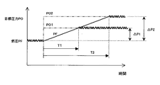
次に、図7のタイミングチャートおよび図8のK2設定マップの説明図を参照しながら、この発明の実施の形態2における積分演算更新禁止手段605による第2の所定時間K2の設定動作について説明する。
図7は一般的なフィードバック制御特性を示しており、図7において、横軸は時間経過を示し、縦軸は目標圧力PO(2点鎖線)および燃圧PF(実線)の各制御状態を示している。
また、図8は図7の制御特性を圧力偏差△PFと演算回数K2との関係で示している。
Next, referring to the timing chart of FIG. 7 and the explanatory diagram of the K2 setting map of FIG. 8, the setting operation of the second predetermined time K2 by the integral calculation update prohibiting means 605 in the second embodiment of the present invention will be described. .
FIG. 7 shows general feedback control characteristics. In FIG. 7, the horizontal axis shows the passage of time, and the vertical axis shows each control state of the target pressure PO (two-dot chain line) and the fuel pressure PF (solid line). Yes.
FIG. 8 shows the control characteristics of FIG. 7 in relation to the pressure deviation ΔPF and the number of operations K2.
周知のように、適切なフィードバック制御状態において、圧力偏差△PFが大きな値になるにつれて、燃圧PFが目標圧力POに達するまでに要する時間は長くなり、多くのフィードバック演算回数を要することになる。このようなフィードバック制御特性は、たとえば、図7のように示される。 As is well known, in an appropriate feedback control state, as the pressure deviation ΔPF increases, the time required for the fuel pressure PF to reach the target pressure PO becomes longer, and a larger number of feedback computations are required. Such a feedback control characteristic is shown, for example, as shown in FIG.
すなわち、目標圧力POが第1の目標圧力PO1に増大変化して、圧力偏差△PFが第1の圧力偏差△P1となったときには、燃圧PFが上昇して第1の目標圧力PO1と一致するまでに時間T1を要する。
一方、目標圧力POが第2の目標圧力PO2(>PO1)に増大変化して、圧力偏差△PFが第2の圧力偏差△P2(>ΔP1)となったときには、燃圧PFが上昇して第2の目標圧力PO2と一致するまでに時間T2(>T1)を要する。
That is, when the target pressure PO is increased and changed to the first target pressure PO1 and the pressure deviation ΔPF becomes the first pressure deviation ΔP1, the fuel pressure PF rises to coincide with the first target pressure PO1. It takes time T1 to complete.
On the other hand, when the target pressure PO increases and changes to the second target pressure PO2 (> PO1) and the pressure deviation ΔPF becomes the second pressure deviation ΔP2 (> ΔP1), the fuel pressure PF rises and Time T2 (> T1) is required until it matches the target pressure PO2 of 2.
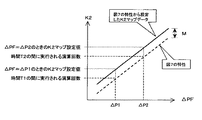
ここで、図7のフィードバック制御特性を、圧力偏差△PFと演算回数K2との関係として示すと、図8内の破線特性のように表すことができる。
そこで、この発明の実施の形態2においては、図8内の破線特性をあらかじめ実験的に計測しておき、この特性値に基づいてK2設定マップ(図8内の実線特性参照)をECU60内に記憶させておく。
Here, when the feedback control characteristic of FIG. 7 is shown as the relationship between the pressure deviation ΔPF and the number of operations K2, it can be expressed as a broken line characteristic in FIG.
Therefore, in
なお、図8内の実線で示すK2設定マップは、あらかじめ実験的に計測した圧力偏差△PFと演算回数との関係(図7に基づく破線特性)に対して、所定演算回数Mだけ加算した値として設定される。
これにより、圧力偏差△PFに応じて積分演算項QFBIの更新禁止期間が不要に長引かない演算回数K2が適切に設定され、積分演算項QFBIが不適切な値で更新禁止されたことに起因して燃圧PFが目標圧力POに一致しなくなったときでも、迅速に積分演算項QFBIの更新を再開させることが可能になる。
Note that the K2 setting map indicated by the solid line in FIG. 8 is a value obtained by adding a predetermined number of operations M to the relationship between the pressure deviation ΔPF experimentally measured in advance and the number of operations (broken line characteristic based on FIG. 7). Set as
As a result, the number K2 of operations in which the update prohibition period of the integral calculation term QFBI is not unnecessarily prolonged is appropriately set according to the pressure deviation ΔPF, and the update is prohibited due to an inappropriate value of the integral calculation term QFBI. Thus, even when the fuel pressure PF does not coincide with the target pressure PO, it is possible to quickly restart the update of the integral calculation term QFBI.
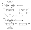
次に、図9のフローチャートを参照しながら、この発明の実施の形態2における積分演算更新禁止手段605による積分演算更新禁止フラグFS(前述の判定ステップS107で用いられる)の設定処理について、具体的に説明する。
この場合、積分演算更新禁止手段605は、圧力偏差△PFの符号が反転しない状態の継続時間(演算回数K2に対応)を計測するためのカウンタC2を有している。
Next, with reference to the flowchart of FIG. 9, the setting process of the integral calculation update prohibition flag FS (used in the above-described determination step S107) by the integral calculation update prohibiting means 605 in the second embodiment of the present invention is specifically described. Explained.
In this case, the integral calculation update prohibiting means 605 has a counter C2 for measuring the duration (corresponding to the calculation count K2) in which the sign of the pressure deviation ΔPF is not reversed.
図9において、積分演算更新禁止手段605は、まず、前述(図5参照)のフローチャートで前回演算実行時に設定された積分演算更新禁止フラグFSの前回値FSoldが「0」であって、かつ、今回の演算実行時に設定された積分演算更新禁止フラグFSが「1」であるか否かを判定する(ステップS301)。 9, the integral calculation update prohibiting means 605 first has the previous value FSold of the integral calculation update prohibition flag FS set when executing the previous calculation in the flowchart of FIG. 5 (see FIG. 5), and It is determined whether or not the integral calculation update prohibition flag FS set at the time of execution of the current calculation is “1” (step S301).
ステップS301において、「FSold=0、かつ、FS=1」(すなわち、YES)と判定されれば、K2設定マップ(図8内の実線特性で示すマップデータ)を用いて、圧力偏差△PFに対応する第2の所定演算回数K2を決定し(ステップS302)、次の判定処理(ステップS303)に進む。
一方、ステップS301において、「FSold≠0、または、FS=0」(すなわち、NO)と判定されれば、直ちにステップS303に進む。
If it is determined in step S301 that “FSold = 0 and FS = 1” (ie, YES), the pressure deviation ΔPF is set using the K2 setting map (map data indicated by the solid line characteristics in FIG. 8). A corresponding second predetermined number of operations K2 is determined (step S302), and the process proceeds to the next determination process (step S303).
On the other hand, if it is determined in step S301 that “FSold ≠ 0 or FS = 0” (that is, NO), the process immediately proceeds to step S303.
続いて、ステップS303においては、積分演算更新禁止フラグFSの状態が「1」にセットされているか否かを判定する。
ステップS303において、FS=1(すなわち、YES)と判定されれば、積分演算項QFBIの更新が禁止されているので、カウンタC2の値をC2=C2+1にインクリメントして(ステップS304)、次の判定処理(ステップS306)に進む。
また、ステップS303において、FS=0(すなわち、NO)と判定されれば、積分演算項QFBIの更新が許可されているので、カウンタC2の値をC2=0にリセットして(ステップS305)、直ちに図9の処理ルーチンを抜け出る。
Subsequently, in step S303, it is determined whether or not the state of the integral calculation update prohibition flag FS is set to “1”.
If it is determined in step S303 that FS = 1 (that is, YES), updating of the integral calculation term QFBI is prohibited, so the value of the counter C2 is incremented to C2 = C2 + 1 (step S304), and the next Proceed to the determination process (step S306).
If it is determined in step S303 that FS = 0 (that is, NO), updating of the integral calculation term QFBI is permitted, so the value of the counter C2 is reset to C2 = 0 (step S305), The processing routine of FIG. 9 is immediately exited.
一方、カウンタC2のインクリメント処理(ステップS304)に続くステップS306においては、カウンタC2の値が所定値K2に達したか否かを判定する。
ステップS306において、C2≧K2(すなわち、YES)と判定されれば、積分演算更新禁止フラグFSを「0」にリセットして(ステップS307)、図9の処理ルーチンを抜け出る。
一方、ステップS306において、C2<K2(すなわち、NO)と判定されれば、直ちに図9の処理ルーチンを抜け出る。
On the other hand, in step S306 following the increment process of the counter C2 (step S304), it is determined whether or not the value of the counter C2 has reached a predetermined value K2.
If it is determined in step S306 that C2 ≧ K2 (that is, YES), the integral calculation update prohibition flag FS is reset to “0” (step S307), and the process routine of FIG. 9 is exited.
On the other hand, if it is determined in step S306 that C2 <K2 (that is, NO), the process routine of FIG. 9 is immediately exited.
以下、積分演算更新禁止フラグFSの判定処理(図4内のステップS107)が実行される。
すなわち、FS=0の場合には、積分演算項QFBIが更新され(図4内のステップS108)、FS=1の場合には、積分演算項QFBIの更新が禁止され(図4内のステップS109)、これに続いて、図4のステップS110〜S112の処理が実行される。
Thereafter, the determination process of the integral calculation update prohibition flag FS (step S107 in FIG. 4) is executed.
That is, when FS = 0, the integral calculation term QFBI is updated (step S108 in FIG. 4), and when FS = 1, the update of the integral calculation term QFBI is prohibited (step S109 in FIG. 4). Subsequently, the processes of steps S110 to S112 in FIG. 4 are executed.
以上のように、この発明の実施の形態2に係る内燃機関の高圧燃料ポンプ制御装置において、積分演算更新禁止手段605は、圧力偏差ΔPFの符号が反転しないまま燃料吐出フィードバック量QFBの演算回数が第1の所定回数K1に達し、かつ積分演算項QFBIの更新を禁止した時点から圧力偏差ΔPFの符号が一度も反転しないまま燃料吐出フィードバック量QFBIの演算回数が第2の所定回数K2(期間N2に相当)に達したとき、積分演算項QFBIの更新を再開させる。
また、第2の所定回数K2は、圧力偏差ΔPFの符号が反転しないまま燃料吐出フィードバック量QFBIの演算回数が第1の所定回数K1に達したことに応答して、積分演算項QFBIの更新を禁止した時点(時刻t12)の圧力偏差の大きさに応じた異なる値に設定される。
As described above, in the high-pressure fuel pump control apparatus for an internal combustion engine according to
The second predetermined number of times K2 updates the integral calculation term QFBI in response to the calculation number of the fuel discharge feedback amount QFBI reaching the first predetermined number of times K1 without the sign of the pressure deviation ΔPF being inverted. It is set to a different value according to the magnitude of the pressure deviation at the time of prohibition (time t12).
これにより、前述の実施の形態1の効果に加えて、積分演算項QFBIの更新禁止時点での圧力偏差△PFに応じて、積分演算項QFBIの更新禁止期間が不要に長引かない演算回数K2が適切に設定され、積分演算項QFBIが不適切な値で更新禁止されたことに起因して燃圧PFが目標圧力POに一致しなくなったときでも、迅速に積分演算項QFBIの更新を再開させることができる。 As a result, in addition to the effect of the first embodiment, the number of operations K2 in which the update prohibition period of the integral calculation term QFBI is not unnecessarily prolonged is determined according to the pressure deviation ΔPF at the update prohibition time of the integral calculation term QFBI. Even when the fuel pressure PF does not coincide with the target pressure PO due to the appropriate setting and the update of the integral calculation term QFBI being prohibited by an inappropriate value, the update of the integral calculation term QFBI is quickly resumed. Can do.
実施の形態3.
なお、上記実施の形態1、2では、圧力偏差ΔPFのみに基づいて、積分演算更新禁止フラグFSを設定したが、圧力偏差ΔPFのみならず、燃圧PFを参照して、積分演算更新禁止フラグFSを設定してもよい。
以下、図面を参照しながら、この発明の実施の形態3に係る内燃機関の高圧燃料ポンプ制御装置について説明する。
Embodiment 3 FIG.
In the first and second embodiments, the integral calculation update prohibition flag FS is set based on only the pressure deviation ΔPF. However, the integral calculation update prohibition flag FS is referred to not only from the pressure deviation ΔPF but also from the fuel pressure PF. May be set.
Hereinafter, a high-pressure fuel pump control apparatus for an internal combustion engine according to Embodiment 3 of the present invention will be described with reference to the drawings.
この場合、ECU60内の積分演算更新禁止手段605は、圧力偏差ΔPFの符号が反転しないまま、燃料吐出フィードバック量QFBの演算回数が第3の所定回数K3だけ経過する間における畜圧室36内の燃圧PFの変化量が所定量以上の変化を示していなかったときに、FS=1として、燃料吐出フィードバック量QFBにおける積分演算項QFBIの更新を禁止し、その後に圧力偏差ΔPFの符号が反転したときに、FS=0として、積分演算項QFBIの更新を再開させる。
In this case, the integral calculation update prohibiting means 605 in the
なお、この発明の実施の形態3の概略構成およびECU60の制御機能については、前述(図1、図2)に示した通りなので、ここでは詳述を省略し、この発明の実施の形態3を特徴付ける積分演算更新禁止手段605の追加機能動作のみについて説明する。
すなわち、この発明の実施の形態3に係る積分演算更新禁止手段605には、燃圧センサ61で検出される燃圧PFが追加入力されており、前述の実施の形態1、2の機能に加えて、燃圧PFに基づく積分演算更新禁止フラグFSの設定機能が追加されている。
Since the schematic configuration of the third embodiment of the present invention and the control function of the
That is, the fuel pressure PF detected by the
次に、図1および図2とともに、図10のタイミングチャートを参照しながら、この発明の実施の形態3における積分演算更新禁止手段605による積分演算更新禁止フラグFSの設定動作および積分演算部623による制御動作について説明する。
図10において、横軸は時間経過を示し、各制御動作の要所となる時刻位置のみに対してt20〜t25までの符号が付されている。
Next, referring to the timing chart of FIG. 10 together with FIGS. 1 and 2, the setting operation of the integral calculation update prohibition flag FS by the integral calculation update prohibiting means 605 and the
In FIG. 10, the horizontal axis indicates the passage of time, and reference numerals t20 to t25 are attached only to the time position that is a key point of each control operation.
また、時刻t21〜t22で示す期間N1は、前述(図3、図6参照)と同様に、燃料吐出フィードバック量QFBの演算が第1の所定回数K1だけ実行されるのに要する時間を示し、時刻t22〜t24で示す期間N2は、燃料吐出フィードバック量QFBの演算が第2の所定回数K2(>K1)だけ実行されるのに要する時間を示している。
一方、時刻t24〜t25で示す期間N3は、燃料吐出フィードバック量QFBの演算が第3の所定回数K3だけ実行されるのに要する時間を示している。
Further, the period N1 indicated by the times t21 to t22 indicates the time required for the calculation of the fuel discharge feedback amount QFB to be executed for the first predetermined number of times K1, as described above (see FIGS. 3 and 6). A period N2 indicated by times t22 to t24 indicates a time required for the calculation of the fuel discharge feedback amount QFB to be executed a second predetermined number of times K2 (> K1).
On the other hand, a period N3 indicated by times t24 to t25 indicates a time required for the calculation of the fuel discharge feedback amount QFB to be executed a third predetermined number of times K3.
また、図10内の縦軸は、前述と同様に、上から順番に、目標圧力PO(2点鎖線)および燃圧PF(実線)、圧力偏差△PF(=PO−PF)、積分演算更新禁止フラグFS、積分演算項QFBIの各制御状態を示している。
さらに、図10内の積分演算更新禁止フラグFSおよび積分演算項QFBIに関して、この発明の実施の形態3を適用したときの各動作は実線で示され、この発明の実施の形態3が適用されなかったときの各動作は点線で示されている。
In addition, the vertical axis in FIG. 10 indicates the target pressure PO (two-dot chain line) and fuel pressure PF (solid line), pressure deviation ΔPF (= PO−PF), integral calculation update prohibition in order from the top, as described above. Each control state of the flag FS and the integral calculation term QFBI is shown.
Further, with respect to integral calculation update prohibition flag FS and integral calculation term QFBI in FIG. 10, each operation when the third embodiment of the present invention is applied is shown by a solid line, and the third embodiment of the present invention is not applied. Each operation is indicated by a dotted line.
図10において、まず、時刻t20〜t21の期間では、前述と同様に、燃圧PFが目標圧力POとほぼ一致した状態で適正にフィードバック制御されているので、△PF(=PO−PF)の符号もフィードバック制御に同期して「+」および「−」の反転を繰り返している。 In FIG. 10, first, during the period from time t20 to t21, as described above, since the fuel pressure PF is appropriately feedback controlled in a state where it substantially coincides with the target pressure PO, the sign of ΔPF (= PO−PF) Also, inversion of “+” and “−” is repeated in synchronization with the feedback control.
すなわち、積分演算項QFBIは、圧力偏差△PFの符号の反転に同期して、前述の式(2)、式(3)を逐次切替えられて演算されており、この状態においては、圧力偏差△PFの符号が反転しないまま燃料吐出フィードバック量QFBの演算回数が第1の所定回数K1に達することはない。
したがって、時刻t20〜t21の期間に積分演算更新禁止フラグFSが「1」にセットされることはない。
That is, the integral calculation term QFBI is calculated by sequentially switching the above equations (2) and (3) in synchronization with the inversion of the sign of the pressure deviation ΔPF. In this state, the pressure deviation Δ The number of times of calculation of the fuel discharge feedback amount QFB does not reach the first predetermined number K1 without inverting the sign of PF.
Therefore, the integral calculation update prohibition flag FS is not set to “1” during the period from time t20 to t21.
また、前述(図6内の時刻t11)と同様に、時刻t21の時点では、目標圧力POが大きな値に変更されたことにより、変更された目標圧力POと燃圧PFとの間に「+符号」の大きな圧力偏差△PFが発生するので、時刻t21の直後においては、圧力偏差△PFが「+符号」の状態がしばらく継続する。 Similarly to the above (time t11 in FIG. 6), at time t21, the target pressure PO is changed to a large value, and therefore, a “+ sign” is added between the changed target pressure PO and the fuel pressure PF. ”Is generated, and immediately after time t21, the state where the pressure deviation ΔPF is“ + sign ”continues for a while.
また、目標圧力POが大きな値に変更された時刻t21の直後では、圧力偏差△PFが「+符号」となり、積分演算項QFBIの演算処理として前述の式(2)が選択されることから、積分演算項QFBIが増加を開始するものの、圧力偏差△PFの符号が「+符号」から「−符号」に反転しないまま燃料吐出フィードバック量QFBの演算回数が第1の所定回数K1に達した(時間に換算して、期間N1が経過した)ことが判定された時点(時刻t22)で、積分演算更新禁止フラグFSが「1」にセットされて、積分演算項QFBIの更新が禁止されるので、積分演算項QFBIが過大になることはない。 Further, immediately after the time t21 when the target pressure PO is changed to a large value, the pressure deviation ΔPF becomes “+ sign”, and the above equation (2) is selected as the calculation processing of the integral calculation term QFBI. Although the integral calculation term QFBI starts to increase, the number of calculation of the fuel discharge feedback amount QFB reaches the first predetermined number K1 without the sign of the pressure deviation ΔPF being inverted from “+ sign” to “− sign” ( At the time (time t22) when it is determined that the period N1 has elapsed (converted to time), the integral calculation update prohibition flag FS is set to “1”, and the update of the integral calculation term QFBI is prohibited. The integral operation term QFBI is never excessive.
また、前述(図6内の時刻t13)と同様に、時刻t23の時点で燃圧PFの上昇が飽和してしまった場合には、たとえば前述の実施の形態2のように、積分演算項QFBIの更新を禁止した時点(時刻t22)からフィードバック量演算手段602の演算回数が第2の所定回数K2に達したとき(時間に換算して、期間N2が経過したとき)に、圧力偏差△PFの符号が一度も反転していなくても、時刻t24の時点で、FS=0にリセットして積分演算項QFBIの更新を再開させることにより、積分演算項QFBIが適正値に移行させることが有効である。 Similarly to the above (time t13 in FIG. 6), when the increase in the fuel pressure PF is saturated at the time t23, for example, as in the second embodiment, the integral calculation term QFBI is changed. When the number of computations of the feedback amount computation means 602 reaches the second predetermined number K2 from the time when the update is prohibited (time t22) (when the period N2 has elapsed in terms of time), the pressure deviation ΔPF Even if the sign has never been reversed, it is effective that the integral calculation term QFBI shifts to an appropriate value by resetting FS = 0 and restarting the update of the integral calculation term QFBI at the time t24. is there.
しかしながら、時刻t24の時点で積分演算項QFBIの更新を再開したとしても、燃圧PFおよび圧力偏差△PFの動作(図10内の時刻t24の以降の点線参照)で示すように、燃圧PFの上昇が再開されない可能性も想定される。
このような場合としては、前述のように、流量制御弁10の特性のばらつき、カム25の磨耗、または、低圧通路33と加圧室23とを接続する燃料通路の目詰まりなどにより、高圧燃料ポンプ20の燃料吐出量特性が正規特性よりも低下した場合が考えられる。
However, even if the update of the integral calculation term QFBI is restarted at time t24, as shown by the operation of the fuel pressure PF and the pressure deviation ΔPF (see the dotted line after time t24 in FIG. 10), the fuel pressure PF increases. It is also possible that will not resume.
In such a case, as described above, the high-pressure fuel is caused by variations in the characteristics of the
また、内燃機関40が高負荷運転に向かう過渡状態において、燃圧PFを上昇させるために必要な燃料吐出フィードバック量QFBが増加しているにもかかわらず、燃料噴射量QINJの増加量が多いことによって、燃料吐出量のほとんどが燃料噴射量QINJとして消費されてしまい、燃圧PFが目標圧力POに一致するのに要する時間が長くなってしまう場合が考えられる。
これらの場合では、図10内の時刻t25の以降の点線で示すように、積分演算項QFBIの更新再開後に、圧力偏差△PFが「+符号」のままであることに起因して、積分演算項QFBIが過度に増加してしまうことが予想される。
In addition, in the transient state where the
In these cases, as shown by the dotted line after time t25 in FIG. 10, after the renewal of the integral calculation term QFBI, the pressure deviation ΔPF remains “+ sign”, so that the integral calculation It is expected that the term QFBI will increase excessively.
そこで、この発明の実施の形態3では、図10内の時刻t25の以降の実線で示した燃圧PF、圧力偏差△PF、積分演算更新禁止フラグFSおよび積分演算項QFBIの各動作で示すように、圧力偏差△PFの符号が反転しないまま、フィードバック量演算手段602の演算回数が第3の所定回数K3だけ経過する間(時間に換算して、期間N3が経過する間)における燃圧PFの変化量が所定量OFST以上の変化を示していなかったときには、積分演算更新禁止フラグFSを「1」にセットして、積分演算項QFBIの更新を禁止する。 Therefore, in the third embodiment of the present invention, as shown by the operations of the fuel pressure PF, the pressure deviation ΔPF, the integral calculation update prohibition flag FS, and the integral calculation term QFBI indicated by the solid lines after time t25 in FIG. The change in the fuel pressure PF while the sign of the pressure deviation ΔPF is not inverted and the number of computations of the feedback amount computing means 602 is the third predetermined number K3 (while the period N3 is lapsed in terms of time). When the amount does not indicate a change of the predetermined amount OFST or more, the integral calculation update prohibition flag FS is set to “1”, and the update of the integral calculation term QFBI is prohibited.
また、図10には示されていないが、その後に、圧力偏差△PFの符号が反転したときに、積分演算更新禁止フラグFSを「0」にリセットして、積分演算項QFBIの更新を再開させる。
このように、この発明の実施の形態3を適用した場合には、高圧燃料ポンプ20の燃料吐出量が最大値近傍であるか否かにかかわらず、燃圧PFの上昇が飽和してしまったときの積分演算項QFBIが過度に増加することを回避することができる。
Although not shown in FIG. 10, when the sign of the pressure deviation ΔPF is reversed thereafter, the integral calculation update prohibition flag FS is reset to “0” and the update of the integral calculation term QFBI is resumed. Let
As described above, when the third embodiment of the present invention is applied, the increase in the fuel pressure PF is saturated regardless of whether or not the fuel discharge amount of the high-
次に、図2とともに、図11のフローチャートを参照しながら、この発明の実施の形態3における積分演算更新禁止手段605による積分演算更新禁止フラグFS(判定ステップS107で用いられる)の設定処理について、具体的に説明する。
この場合、積分演算更新禁止手段605は、圧力偏差△PFの符号が反転しない状態の継続時間(第3の演算回数K3に対応)を計測するためのカウンタC3と、圧力偏差△PFの符号が反転したときの燃圧PFの現在値を一時記憶するメモリMEMとを有している。
Next, referring to the flowchart of FIG. 11 together with FIG. 2, the setting process of the integral calculation update prohibition flag FS (used in determination step S107) by the integral calculation update prohibiting means 605 in the third embodiment of the present invention will be described. This will be specifically described.
In this case, the integral calculation update prohibiting means 605 has a counter C3 for measuring the duration (corresponding to the third calculation count K3) in which the sign of the pressure deviation ΔPF is not inverted, and the sign of the pressure deviation ΔPF. And a memory MEM for temporarily storing the current value of the fuel pressure PF at the time of inversion.
図11において、積分演算更新禁止手段605は、まず、図4内のステップS105で今回演算した圧力偏差△PFの符号が、前回演算実行時に演算された圧力偏差前回値△PFoldの符号に対して同一であるか否か(反転したか)を判定する(ステップS401)。 In FIG. 11, the integral calculation update prohibiting means 605 first compares the sign of the pressure deviation ΔPF calculated this time in step S105 in FIG. 4 with the sign of the pressure deviation previous value ΔPFold calculated at the time of the previous calculation execution. It is determined whether or not they are the same (inverted) (step S401).
ここで、「△PFoldの符号=△PFの符号」(すなわち、YES)と判定されれば、圧力偏差△PFの符号が反転していないので、カウンタC3をC3=C3+1にインクリメントして(ステップS402)、次の判定処理(ステップS403)に進む。 Here, if it is determined that “the sign of ΔPFold = the sign of ΔPF” (that is, YES), the sign of the pressure deviation ΔPF is not inverted, so the counter C3 is incremented to C3 = C3 + 1 (step S402), the process proceeds to the next determination process (step S403).
一方、ステップS401において、「△PFoldの符号≠△PFの符号」(すなわち、NO)と判定されれば、圧力偏差△PFの符号が反転しているので、カウンタC3をC3=0にリセットして(ステップS406)、燃圧PFの現在値をメモリMEMに一時記憶し(ステップS407)、積分演算更新禁止フラグFSを「0」にリセットして(ステップS408)、図11の処理ルーチンを抜け出る。 On the other hand, if it is determined in step S401 that “the sign of ΔPFold ≠ the sign of ΔPF” (ie, NO), the sign of the pressure deviation ΔPF is inverted, so the counter C3 is reset to C3 = 0. (Step S406), the current value of the fuel pressure PF is temporarily stored in the memory MEM (step S407), the integral calculation update prohibition flag FS is reset to “0” (step S408), and the processing routine of FIG. 11 is exited.
また、カウンタC3のインクリメント処理(ステップS402)に続くステップS403においては、カウンタC3が所定値K3に達したか否かを判定する。
ステップS403において、C3≧K3(すなわち、YES)と判定されれば、圧力偏差△PFの符号が反転しないまま第3の所定回数K3が経過したものと見なして、次の判定処理(ステップS404)に進む。
さらに、ステップS403において、C3<K3(すなわち、NO)と判定されれば、ステップS408に進み、積分演算更新禁止フラグFSを「0」にリセットして、図11の処理ルーチンを抜け出る。
Further, in step S403 following the increment processing of the counter C3 (step S402), it is determined whether or not the counter C3 has reached a predetermined value K3.
If it is determined in step S403 that C3 ≧ K3 (that is, YES), it is considered that the third predetermined number of times K3 has passed without the sign of the pressure deviation ΔPF being inverted, and the next determination process (step S404). Proceed to
Furthermore, if it is determined in step S403 that C3 <K3 (that is, NO), the process proceeds to step S408, the integral calculation update prohibition flag FS is reset to “0”, and the process routine of FIG. 11 is exited.
一方、ステップS403において、C3≧K3(すなわち、YES)と判定された場合には、燃圧PFの現在値が、メモリMEMに一時記憶されている値(演算回数K3だけ前に演算された圧力偏差△PFの値)に所定のオフセット値OFSTを加算した値(MEM+OFST)よりも小さいか否かを判定する(ステップS404)。
なお、オフセット値OFSTは、第3の所定回数K3だけ積分演算項QFBIが増加したときに、燃圧PFが増加するであろうと推定される圧力変化分に基づいて、あらかじめ設定されている値である。
On the other hand, if it is determined in step S403 that C3 ≧ K3 (that is, YES), the current value of the fuel pressure PF is a value temporarily stored in the memory MEM (the pressure deviation calculated before the calculation count K3). It is determined whether or not it is smaller than a value (MEM + OFST) obtained by adding a predetermined offset value OFST to (ΔPF value) (step S404).
The offset value OFST is a value set in advance based on the pressure change that is estimated to increase the fuel pressure PF when the integral calculation term QFBI increases by the third predetermined number of times K3. .
ステップS404において、PF<MEM+OFST(すなわち、YES)と判定されれば、圧力偏差△PFの符号が反転しないままフィードバック量演算手段602の演算回数が第3の所定回数K3だけ経過する間における燃圧PFの変化量が、オフセット値OFST以上の変化を示していない(すなわち、積分演算項QFBIの増加が燃圧PFの増加に反映されていない)ものと見なし、積分演算更新禁止フラグFSを「1」にセットして(ステップS405)、図11の処理ルーチンを抜け出る。 If it is determined in step S404 that PF <MEM + OFST (that is, YES), the fuel pressure PF while the number of calculations of the feedback amount calculation means 602 has passed the third predetermined number K3 without inverting the sign of the pressure deviation ΔPF. Is not indicative of a change greater than or equal to the offset value OFST (that is, the increase in the integral calculation term QFBI is not reflected in the increase in the fuel pressure PF), and the integral calculation update prohibition flag FS is set to “1”. After setting (step S405), the process routine of FIG. 11 is exited.
一方、ステップS404において、PF≧MEM+OFST(すなわち、NO)と判定されれば、圧力偏差△PFの符号が反転しないまま、フィードバック量演算手段602の演算回数が第3の所定回数K3だけ経過する間における燃圧PFの変化量がオフセット値OFST以上の変化を示した(すなわち、積分演算項QFBIの増加に応じて燃圧PFが上昇している)ものと見なし、ステップS408に進んで、積分演算更新禁止フラグFSを「0」にリセットして、図11の処理ルーチンを抜け出る。 On the other hand, if it is determined in step S404 that PF ≧ MEM + OFST (that is, NO), while the sign of the pressure deviation ΔPF is not inverted, the number of computations of the feedback amount computing means 602 passes the third predetermined number K3. It is assumed that the amount of change in the fuel pressure PF at the time has changed more than the offset value OFST (that is, the fuel pressure PF has increased in accordance with the increase in the integral calculation term QFBI), and the process proceeds to step S408 to prohibit the integral calculation update. The flag FS is reset to “0” and the processing routine of FIG. 11 is exited.
以下、図4内のステップS107による積分演算更新禁止フラグFSの判定処理が行われる。
すなわち、FS=0の場合には積分演算項QFBIが更新され(ステップS108)、FS=1の場合には積分演算項QFBIの更新が禁止され(ステップS109)、続いて、ステップS110〜S112の処理が実行される。
Thereafter, the determination process of the integral calculation update prohibition flag FS in step S107 in FIG. 4 is performed.
That is, when FS = 0, the integral calculation term QFBI is updated (step S108), and when FS = 1, the update of the integral calculation term QFBI is prohibited (step S109). Subsequently, steps S110 to S112 are performed. Processing is executed.
このように、この発明の実施の形態3による積分演算更新禁止手段605は、圧力偏差△PFの符号が反転しないまま演算処理回数が第3の所定回数K3だけ経過する期間N3における燃圧PFの変化量が所定量以上の変化を示していなかったときに、積分演算更新禁止フラグFSを「1」にセットして積分演算項QFBIの更新を禁止し、その後に圧力偏差△PFの符号が反転したときに積分演算更新禁止フラグFSを「0」にリセットして積分演算項QFBIの更新を再開させるので、前述の実施の形態1の効果に加えて、高圧燃料ポンプ20の燃料吐出量が最大値近傍であるか否かにかかわらず、燃圧PFの上昇が飽和してしまったときの積分演算項QFBIが過度に増加することを回避することができる。
As described above, the integral calculation update prohibiting means 605 according to the third embodiment of the present invention changes the fuel pressure PF in the period N3 in which the number of calculation processes is the third predetermined number K3 without inverting the sign of the pressure deviation ΔPF. When the amount did not change more than the predetermined amount, the integral operation update prohibition flag FS is set to “1” to prohibit the update of the integral operation term QFBI, and then the sign of the pressure deviation ΔPF is inverted. In some cases, the integral calculation update prohibition flag FS is reset to “0” and the update of the integral calculation term QFBI is restarted. Therefore, in addition to the effect of the first embodiment, the fuel discharge amount of the high-
なお、上記実施の形態3では、前述の実施の形態1、2の構成に組み合わせた場合について説明したが、各種センサ62、63と、高圧燃料ポンプ20と、流量制御弁10と、畜圧室36と、燃料噴射弁39と、燃圧センサ39と、目標圧力設定手段601と、フィードバック量演算手段602と、流量制御弁制御手段603とを備えた内燃機関の高圧燃料ポンプ制御装置に対して、積分演算更新禁止手段605を設け、圧力偏差ΔPFの符号が反転しないまま燃料吐出フィードバック量QFBの演算回数が所定回数K3だけ経過する間における畜圧室36内の燃圧PFの変化量が所定量以上の変化を示していなかったときに、燃料吐出フィードバック量QFBにおける積分演算項QFBIの更新を禁止し、その後に圧力偏差ΔPFの符号が反転したときに、積分演算項QFBIの更新を再開させてもよい。
これにより、前述と同様に、燃圧PFのオーバーシュートやアンダーシュートの発生を回避するとともに、高圧燃料ポンプ20の燃料吐出量が最大値近傍であるか否かにかかわらず、燃圧PFの上昇が飽和してしまったときの積分演算項QFBIが過度に増加することを回避することができる。
In the third embodiment, the case of combining with the configuration of the first and second embodiments has been described. However,
This avoids the occurrence of overshoot and undershoot of the fuel pressure PF as described above, and saturates the increase in the fuel pressure PF regardless of whether or not the fuel discharge amount of the high-
10 流量制御弁、12 ソレノイド、20 高圧燃料ポンプ、36 蓄圧室、39 燃料噴射弁、40 内燃機関、60 ECU、61 燃圧センサ、62 クランク角センサ、63 アクセルポジションセンサ、601 目標圧力設定手段、602 フィードバック量演算手段、603 流量制御弁制御手段、604 燃料噴射量演算手段、605 積分演算更新禁止手段、621 減算器、622 比例演算部、623 積分演算部、631 加算器、632 駆動タイミング設定手段、AP アクセルペダル踏込量、FS 積分演算更新禁止フラグ、K1 第1の所定回数、K2 第2の所定回数、K3 第3の所定回数(所定回数)、NE 回転速度、PF 燃圧(燃圧センサ61の検出値)、PO 目標圧力、ΔPF 圧力偏差、QFBP 比例演算項、QFBI 積分演算項、QFB 燃料吐出フィードバック量、QINJ 燃料噴射量、QO 目標燃料吐出量、TD 駆動タイミング。
DESCRIPTION OF
Claims (5)
吸入された低圧の燃料を加圧して吐出する高圧燃料ポンプと、
駆動タイミングが設定されることにより前記高圧燃料ポンプから吐出される燃料量を調整する流量制御弁と、
前記高圧燃料ポンプから吐出された燃料を畜圧する畜圧室と、
前記畜圧室内の燃料を前記内燃機関の各燃焼室に噴射供給する燃料噴射弁と、
前記蓄圧室内の燃圧を検出する燃圧センサと、
前記運転状態に基づいて前記畜圧室内の目標圧力を設定する目標圧力設定手段と、
前記目標圧力と前記燃圧センサで検出された燃圧との圧力偏差に基づく比例積分演算により前記高圧燃料ポンプの燃料吐出フィードバック量を演算するフィードバック量演算手段と、
前記燃料噴射弁から噴射される燃料噴射量と前記燃料吐出フィードバック量とを加算して求めた目標燃料吐出量に基づいて前記流量制御弁の駆動タイミングを設定する流量制御弁制御手段と、
を備えた内燃機関の高圧燃料ポンプ制御装置において、
積分演算更新禁止手段をさらに備え、
前記積分演算更新禁止手段は、
前記圧力偏差の符号が反転しないまま前記燃料吐出フィードバック量の演算回数が第1の所定回数に達したときに、前記燃料吐出フィードバック量における積分演算項の更新を禁止し、
その後に前記圧力偏差の符号が反転したときに、前記積分演算項の更新を再開させることを特徴とする内燃機関の高圧燃料ポンプ制御装置。 Various sensors for detecting the operating state of the internal combustion engine;
A high pressure fuel pump that pressurizes and discharges the sucked low pressure fuel; and
A flow rate control valve that adjusts the amount of fuel discharged from the high-pressure fuel pump by setting a drive timing; and
A stocking pressure chamber for stocking the fuel discharged from the high-pressure fuel pump;
A fuel injection valve that injects fuel in the stock pressure chamber into each combustion chamber of the internal combustion engine;
A fuel pressure sensor for detecting a fuel pressure in the pressure accumulation chamber;
Target pressure setting means for setting a target pressure in the animal pressure chamber based on the operating state;
Feedback amount calculation means for calculating a fuel discharge feedback amount of the high-pressure fuel pump by a proportional-integral calculation based on a pressure deviation between the target pressure and the fuel pressure detected by the fuel pressure sensor;
Flow rate control valve control means for setting the drive timing of the flow rate control valve based on a target fuel discharge amount obtained by adding the fuel injection amount injected from the fuel injection valve and the fuel discharge feedback amount;
In a high-pressure fuel pump control device for an internal combustion engine comprising:
Further provided with integral calculation update prohibiting means,
The integral calculation update prohibiting means includes:
When the number of calculations of the fuel discharge feedback amount reaches the first predetermined number without reversing the sign of the pressure deviation, the integral calculation term in the fuel discharge feedback amount is prohibited from being updated,
After that, when the sign of the pressure deviation is reversed, the update of the integral calculation term is restarted.
前記圧力偏差の符号が反転しないまま前記燃料吐出フィードバック量の演算回数が前記第1の所定回数に達し、かつ前記積分演算項の更新を禁止した時点から前記圧力偏差の符号が一度も反転しないまま前記燃料吐出フィードバック量の演算回数が第2の所定回数に達したときに、
前記積分演算項の更新を再開させることを特徴とする請求項1に記載の内燃機関の高圧燃料ポンプ制御装置。 The integral calculation update prohibiting means includes:
While the sign of the pressure deviation is not reversed, the number of times of calculation of the fuel discharge feedback amount reaches the first predetermined number of times, and the sign of the pressure deviation is never reversed since the update of the integral calculation term is prohibited. When the number of calculations of the fuel discharge feedback amount reaches the second predetermined number of times,
The high-pressure fuel pump control device for an internal combustion engine according to claim 1, wherein updating of the integral calculation term is resumed.
前記圧力偏差の符号が反転しないまま前記燃料吐出フィードバック量の演算回数が前記第1の所定回数に達したことに応答して、前記積分演算項の更新を禁止した時点の前記圧力偏差の大きさに応じた異なる値に設定されることを特徴とする請求項2に記載の内燃機関の高圧燃料ポンプ制御装置。 The second predetermined number of times is
The magnitude of the pressure deviation at the time when updating of the integral calculation term is prohibited in response to the number of calculations of the fuel discharge feedback amount reaching the first predetermined number without reversing the sign of the pressure deviation. 3. The high-pressure fuel pump control device for an internal combustion engine according to claim 2, wherein different values are set according to the engine.
前記圧力偏差の符号が反転しないまま前記燃料吐出フィードバック量の演算回数が第3の所定回数だけ経過する間における前記畜圧室内の燃圧の変化量が所定量以上の変化を示していなかったときに、前記燃料吐出フィードバック量における積分演算項の更新を禁止し、
その後に前記圧力偏差の符号が反転したときに、前記積分演算項の更新を再開させることを特徴とする請求項1から請求項3までのいずれか1項に記載の内燃機関の高圧燃料ポンプ制御装置。 The integral calculation update prohibiting means includes:
When the change amount of the fuel pressure in the stock pressure chamber does not show a change of a predetermined amount or more while the number of times of calculation of the fuel discharge feedback amount has passed the third predetermined number without reversing the sign of the pressure deviation. , Prohibit the update of the integral calculation term in the fuel discharge feedback amount,
4. The high-pressure fuel pump control for an internal combustion engine according to claim 1, wherein when the sign of the pressure deviation is reversed thereafter, the update of the integral calculation term is resumed. 5. apparatus.
吸入された低圧の燃料を加圧して吐出する高圧燃料ポンプと、
駆動タイミングが設定されることにより前記高圧燃料ポンプから吐出される燃料量を調整する流量制御弁と、
前記高圧燃料ポンプから吐出された燃料を畜圧する畜圧室と、
前記畜圧室内の燃料を前記内燃機関の各燃焼室に噴射供給する燃料噴射弁と、
前記蓄圧室内の燃圧を検出する燃圧センサと、
前記運転状態に基づいて前記畜圧室内の目標圧力を設定する目標圧力設定手段と、
前記目標圧力と前記燃圧センサで検出された燃圧との圧力偏差に基づく比例積分演算により前記高圧燃料ポンプの燃料吐出フィードバック量を演算するフィードバック量演算手段と、
前記燃料噴射弁から噴射される燃料噴射量と前記燃料吐出フィードバック量とを加算して求めた目標燃料吐出量に基づいて前記流量制御弁の駆動タイミングを設定する流量制御弁制御手段と、
を備えた内燃機関の高圧燃料ポンプ制御装置において、
積分演算更新禁止手段をさらに備え、
前記積分演算更新禁止手段は、
前記圧力偏差の符号が反転しないまま前記燃料吐出フィードバック量の演算回数が所定回数だけ経過する間における前記畜圧室内の燃圧の変化量が所定量以上の変化を示していなかったときに、前記燃料吐出フィードバック量における積分演算項の更新を禁止し、
その後に前記圧力偏差の符号が反転したときに、前記積分演算項の更新を再開させることを特徴とする内燃機関の高圧燃料ポンプ制御装置。 Various sensors for detecting the operating state of the internal combustion engine;
A high pressure fuel pump that pressurizes and discharges the sucked low pressure fuel; and
A flow rate control valve that adjusts the amount of fuel discharged from the high-pressure fuel pump by setting a drive timing; and
A stocking pressure chamber for stocking the fuel discharged from the high-pressure fuel pump;
A fuel injection valve that injects fuel in the stock pressure chamber into each combustion chamber of the internal combustion engine;
A fuel pressure sensor for detecting a fuel pressure in the pressure accumulation chamber;
Target pressure setting means for setting a target pressure in the animal pressure chamber based on the operating state;
Feedback amount calculation means for calculating a fuel discharge feedback amount of the high-pressure fuel pump by a proportional-integral calculation based on a pressure deviation between the target pressure and the fuel pressure detected by the fuel pressure sensor;
Flow rate control valve control means for setting the drive timing of the flow rate control valve based on a target fuel discharge amount obtained by adding the fuel injection amount injected from the fuel injection valve and the fuel discharge feedback amount;
In a high-pressure fuel pump control device for an internal combustion engine comprising:
Further provided with integral calculation update prohibiting means,
The integral calculation update prohibiting means includes:
When the change amount of the fuel pressure in the stock pressure chamber does not show a change of a predetermined amount or more while the number of times of calculation of the fuel discharge feedback amount has passed a predetermined number without reversing the sign of the pressure deviation, the fuel Prohibit updating of integral calculation term in discharge feedback amount,
After that, when the sign of the pressure deviation is reversed, the update of the integral calculation term is restarted.
Priority Applications (3)
| Application Number | Priority Date | Filing Date | Title |
|---|---|---|---|
| JP2006022591A JP4170345B2 (en) | 2006-01-31 | 2006-01-31 | High pressure fuel pump control device for internal combustion engine |
| US11/455,154 US7171944B1 (en) | 2006-01-31 | 2006-06-19 | High-pressure fuel pump control device for internal combustion |
| DE102006035826.0A DE102006035826B4 (en) | 2006-01-31 | 2006-08-01 | High pressure fuel pump control device for an internal combustion engine |
Applications Claiming Priority (1)
| Application Number | Priority Date | Filing Date | Title |
|---|---|---|---|
| JP2006022591A JP4170345B2 (en) | 2006-01-31 | 2006-01-31 | High pressure fuel pump control device for internal combustion engine |
Publications (2)
| Publication Number | Publication Date |
|---|---|
| JP2007205193A true JP2007205193A (en) | 2007-08-16 |
| JP4170345B2 JP4170345B2 (en) | 2008-10-22 |
Family
ID=37696504
Family Applications (1)
| Application Number | Title | Priority Date | Filing Date |
|---|---|---|---|
| JP2006022591A Expired - Fee Related JP4170345B2 (en) | 2006-01-31 | 2006-01-31 | High pressure fuel pump control device for internal combustion engine |
Country Status (3)
| Country | Link |
|---|---|
| US (1) | US7171944B1 (en) |
| JP (1) | JP4170345B2 (en) |
| DE (1) | DE102006035826B4 (en) |
Cited By (2)
| Publication number | Priority date | Publication date | Assignee | Title |
|---|---|---|---|---|
| WO2023243032A1 (en) * | 2022-06-16 | 2023-12-21 | 日立Astemo株式会社 | Internal combustion engine control device |
| WO2025069150A1 (en) * | 2023-09-25 | 2025-04-03 | 日立Astemo株式会社 | Internal combustion engine system |
Families Citing this family (8)
| Publication number | Priority date | Publication date | Assignee | Title |
|---|---|---|---|---|
| DE102005020686B4 (en) * | 2005-05-03 | 2007-08-02 | Siemens Ag | Method and device for controlling a fuel supply device of an internal combustion engine |
| ATE467045T1 (en) * | 2006-11-16 | 2010-05-15 | Fiat Ricerche | IMPROVED FUEL INJECTION SYSTEM FOR AN INTERNAL COMBUSTION ENGINE |
| JP4609524B2 (en) * | 2008-05-09 | 2011-01-12 | 株式会社デンソー | Fuel pressure control device and fuel pressure control system |
| DE102009031528B3 (en) * | 2009-07-02 | 2010-11-11 | Mtu Friedrichshafen Gmbh | Method for controlling and regulating an internal combustion engine |
| DE102009031527B3 (en) * | 2009-07-02 | 2010-11-18 | Mtu Friedrichshafen Gmbh | Method for controlling and regulating an internal combustion engine |
| EP2295774A1 (en) * | 2009-08-18 | 2011-03-16 | Delphi Technologies Holding S.à.r.l. | Control method for a common rail fuel pump and apparatus for performing the same |
| DE102010016814B3 (en) * | 2010-05-05 | 2011-10-06 | Schott Solar Ag | Method and device for applying solder to a workpiece |
| DE102015203348B3 (en) * | 2015-02-25 | 2016-02-18 | Ford Global Technologies, Llc | Method for operating a common rail injection arrangement for an internal combustion engine with a stop-start system |
Family Cites Families (16)
| Publication number | Priority date | Publication date | Assignee | Title |
|---|---|---|---|---|
| JPH0730728B2 (en) * | 1987-05-30 | 1995-04-10 | マツダ株式会社 | Engine idle speed controller |
| JP2867815B2 (en) | 1992-10-22 | 1999-03-10 | トヨタ自動車株式会社 | Fuel pressure control device for internal combustion engine |
| US5623914A (en) * | 1994-05-09 | 1997-04-29 | Nissan Motor Co., Ltd. | Air/fuel ratio control apparatus |
| JPH08261045A (en) * | 1995-03-27 | 1996-10-08 | Toyota Motor Corp | Air-fuel ratio control device for internal combustion engine |
| JP3453970B2 (en) * | 1995-12-12 | 2003-10-06 | 株式会社デンソー | Fuel supply device for internal combustion engine |
| JP3303739B2 (en) * | 1996-12-19 | 2002-07-22 | トヨタ自動車株式会社 | Air-fuel ratio control method for internal combustion engine |
| DE19731995B4 (en) * | 1997-07-25 | 2008-02-21 | Robert Bosch Gmbh | Method and device for controlling an internal combustion engine |
| US6026794A (en) * | 1997-09-11 | 2000-02-22 | Denso Corporation | Control apparatus for internal combustion engine |
| JP2000080955A (en) * | 1998-09-04 | 2000-03-21 | Denso Corp | Air-fuel ratio control device for internal combustion engine |
| DE60045229D1 (en) * | 1999-02-15 | 2010-12-30 | Toyota Motor Co Ltd | A fuel pressure control apparatus and method for a high pressure fuel injection system |
| JP2001159359A (en) * | 1999-12-02 | 2001-06-12 | Mitsubishi Electric Corp | Fuel pressure control device for in-cylinder injection engine |
| JP3714099B2 (en) | 2000-03-23 | 2005-11-09 | トヨタ自動車株式会社 | Fuel pressure control device for internal combustion engine |
| JP2002130014A (en) * | 2000-10-18 | 2002-05-09 | Denso Corp | Fuel supply control device for internal combustion engine |
| JP2003120367A (en) * | 2001-10-15 | 2003-04-23 | Honda Motor Co Ltd | Fuel injection control device for internal combustion engine |
| JP4042058B2 (en) * | 2003-11-17 | 2008-02-06 | 株式会社デンソー | Fuel injection device for internal combustion engine |
| JP4333549B2 (en) * | 2004-10-18 | 2009-09-16 | トヨタ自動車株式会社 | Fuel injection control device for internal combustion engine |
-
2006
- 2006-01-31 JP JP2006022591A patent/JP4170345B2/en not_active Expired - Fee Related
- 2006-06-19 US US11/455,154 patent/US7171944B1/en not_active Expired - Fee Related
- 2006-08-01 DE DE102006035826.0A patent/DE102006035826B4/en not_active Expired - Fee Related
Cited By (5)
| Publication number | Priority date | Publication date | Assignee | Title |
|---|---|---|---|---|
| WO2023243032A1 (en) * | 2022-06-16 | 2023-12-21 | 日立Astemo株式会社 | Internal combustion engine control device |
| JPWO2023243032A1 (en) * | 2022-06-16 | 2023-12-21 | ||
| JP7788553B2 (en) | 2022-06-16 | 2025-12-18 | Astemo株式会社 | Control device for internal combustion engine |
| EP4542020A4 (en) * | 2022-06-16 | 2026-04-08 | Astemo Ltd | CONTROL DEVICE FOR INTERNAL COMBUSTION ENGINE |
| WO2025069150A1 (en) * | 2023-09-25 | 2025-04-03 | 日立Astemo株式会社 | Internal combustion engine system |
Also Published As
| Publication number | Publication date |
|---|---|
| DE102006035826A1 (en) | 2007-08-09 |
| JP4170345B2 (en) | 2008-10-22 |
| US7171944B1 (en) | 2007-02-06 |
| DE102006035826B4 (en) | 2014-03-27 |
Similar Documents
| Publication | Publication Date | Title |
|---|---|---|
| JP3714099B2 (en) | Fuel pressure control device for internal combustion engine | |
| JP4333549B2 (en) | Fuel injection control device for internal combustion engine | |
| JP4023020B2 (en) | Fuel pressure control device for high pressure fuel injection system | |
| JP4349451B2 (en) | Fuel injection control device and fuel injection system using the same | |
| JP2010019088A (en) | Idling stop control device and fuel injection system using same | |
| JP4170345B2 (en) | High pressure fuel pump control device for internal combustion engine | |
| JP2005139975A (en) | Common rail fuel injection system | |
| JP5875970B2 (en) | Automotive fuel supply system | |
| JP2011163220A (en) | Control device for fuel supply system | |
| JP6146274B2 (en) | Control device for internal combustion engine | |
| JP4569598B2 (en) | Pressure reducing valve control device and fuel injection system using the same | |
| JP2010196472A (en) | Fuel supply control device for internal combustion engine | |
| JP6115513B2 (en) | Deposit detection device and fuel injection control device | |
| JP4501776B2 (en) | Control device for fuel supply system | |
| JP4134216B2 (en) | Internal combustion engine control device | |
| WO2016189803A1 (en) | Internal-combustion engine high-pressure pump control device | |
| JP2011196262A (en) | Fuel pressure control device | |
| JP4670832B2 (en) | Pressure control device and fuel injection control system | |
| JP5310139B2 (en) | Fuel injection device for internal combustion engine | |
| JP4281825B2 (en) | Fuel pressure control device for high pressure fuel injection system | |
| JP5110109B2 (en) | Fuel pressure control device | |
| JP4613920B2 (en) | Fuel injection device for internal combustion engine | |
| JP2001295725A (en) | Fuel pressure control device for internal combustion engine | |
| US10132263B2 (en) | Fuel injection control device and method for engine | |
| EP3061956B1 (en) | Control device and control method of fuel pressure of engine |
Legal Events
| Date | Code | Title | Description |
|---|---|---|---|
| A977 | Report on retrieval |
Free format text: JAPANESE INTERMEDIATE CODE: A971007 Effective date: 20071128 |
|
| A131 | Notification of reasons for refusal |
Free format text: JAPANESE INTERMEDIATE CODE: A131 Effective date: 20071211 |
|
| A521 | Request for written amendment filed |
Free format text: JAPANESE INTERMEDIATE CODE: A523 Effective date: 20080207 |
|
| TRDD | Decision of grant or rejection written | ||
| A01 | Written decision to grant a patent or to grant a registration (utility model) |
Free format text: JAPANESE INTERMEDIATE CODE: A01 Effective date: 20080805 |
|
| A01 | Written decision to grant a patent or to grant a registration (utility model) |
Free format text: JAPANESE INTERMEDIATE CODE: A01 |
|
| A61 | First payment of annual fees (during grant procedure) |
Free format text: JAPANESE INTERMEDIATE CODE: A61 Effective date: 20080806 |
|
| FPAY | Renewal fee payment (event date is renewal date of database) |
Free format text: PAYMENT UNTIL: 20110815 Year of fee payment: 3 |
|
| R150 | Certificate of patent or registration of utility model |
Free format text: JAPANESE INTERMEDIATE CODE: R150 |
|
| FPAY | Renewal fee payment (event date is renewal date of database) |
Free format text: PAYMENT UNTIL: 20110815 Year of fee payment: 3 |
|
| FPAY | Renewal fee payment (event date is renewal date of database) |
Free format text: PAYMENT UNTIL: 20120815 Year of fee payment: 4 |
|
| FPAY | Renewal fee payment (event date is renewal date of database) |
Free format text: PAYMENT UNTIL: 20120815 Year of fee payment: 4 |
|
| FPAY | Renewal fee payment (event date is renewal date of database) |
Free format text: PAYMENT UNTIL: 20130815 Year of fee payment: 5 |
|
| R250 | Receipt of annual fees |
Free format text: JAPANESE INTERMEDIATE CODE: R250 |
|
| LAPS | Cancellation because of no payment of annual fees |