JP2007201729A - Adaptive equalizer and receiver - Google Patents
Adaptive equalizer and receiver Download PDFInfo
- Publication number
- JP2007201729A JP2007201729A JP2006016814A JP2006016814A JP2007201729A JP 2007201729 A JP2007201729 A JP 2007201729A JP 2006016814 A JP2006016814 A JP 2006016814A JP 2006016814 A JP2006016814 A JP 2006016814A JP 2007201729 A JP2007201729 A JP 2007201729A
- Authority
- JP
- Japan
- Prior art keywords
- signal
- tap coefficient
- input
- adaptive equalizer
- estimated
- Prior art date
- Legal status (The legal status is an assumption and is not a legal conclusion. Google has not performed a legal analysis and makes no representation as to the accuracy of the status listed.)
- Pending
Links
Images


Abstract
Description
本発明は、適応等化器および受信装置に関するものであり、特に、短い既知系列で高精度に信号歪を補正する適応等化器および当該適応等化器を用いて高品質な復調データを出力する受信装置に関するものである。 The present invention relates to an adaptive equalizer and a receiving apparatus, and more particularly, an adaptive equalizer that corrects signal distortion with high accuracy using a short known sequence, and outputs high-quality demodulated data using the adaptive equalizer. It is related with the receiver which performs.
近年、移動体通信システムや衛星通信システムでは、マルチパス環境下でデータ伝送速度を高速化する際の大きな制約となる周波数選択性フェージングを克服するための技術検討が活発化している。 In recent years, in mobile communication systems and satellite communication systems, technical studies for overcoming frequency selective fading, which is a major limitation in increasing the data transmission speed in a multipath environment, have become active.
適応等化器は、周波数選択性フェージングを克服するための技術の一つであり、周波数選択性フェージングにより発生する信号歪を補正して、高品質な復調データの獲得を可能とする。このため、上記のようなマルチパス環境下に適用される通信システムでは、適応等化器を用いたシステム構成が採用されることが多い。 An adaptive equalizer is one of the techniques for overcoming frequency selective fading, and corrects signal distortion caused by frequency selective fading to enable acquisition of high-quality demodulated data. For this reason, in a communication system applied under the multipath environment as described above, a system configuration using an adaptive equalizer is often employed.
例えば、下記非特許文献1には、従来技術にかかる適応等化器の構成が示されている。この文献に示された適応等化器では、自身の出力でもあるトランスバーサルフィルタからの出力信号(等化信号)とレプリカ信号(自身内部で保持する既知信号)との誤差信号を使用し、LMS(Least Mean Square)アルゴリズムを用いて、トランスバーサルフィルタのタップ係数を信号歪が小さくなるように更新することで、トランスバーサルフィルタにおける適切なタップ係数を推定する技術が開示されている。したがって、この種の適応等化器を受信装置に用いれば、信号歪が低減された等化信号を用いて復調することができるので、より高品質な復調データを出力させることが可能となる。
For example, the following Non-Patent
しかしながら、上記非特許文献1に示される従来技術では、例えば等化器に入力される信号のキャリア位相や振幅がレプリカ信号と大きく異なる場合には、信号歪を補正するためのタップ係数推定に多くの時間を要し、所定シンボル数の既知信号を受信している時間内に適切なタップ係数を推定することができず、復調特性が劣化する場合があるといった問題点があった。
However, in the conventional technique disclosed in
本発明は、上記に鑑みてなされたものであって、入力信号のキャリア位相や振幅に依存することなく、短い既知系列で高精度に信号歪を補正可能な適応等化器を提供することを目的とする。また、この適応等化器を適用することにより、短い既知系列を用いる無線通信システムにおいて、高品質な復調データを出力可能な受信装置を提供することを目的とする。 The present invention has been made in view of the above, and it is an object of the present invention to provide an adaptive equalizer capable of correcting signal distortion with high accuracy with a short known sequence without depending on the carrier phase or amplitude of an input signal. Objective. It is another object of the present invention to provide a receiving apparatus capable of outputting high-quality demodulated data in a wireless communication system using a short known sequence by applying this adaptive equalizer.
上述した課題を解決し、目的を達成するため、本発明にかかる適応等化器は、既知信号を含んだデータフォーマットを有する変調信号に対して、該変調信号の入力時に該既知信号を含む変調信号の所定パラメータを推定し、該推定した所定パラメータに基づいて補正した補正信号を出力する入力信号補正手段と、前記入力信号補正手段の出力信号に対して、予め推定されたタップ係数を個々のタップごとに重み付けした後の加算結果を等化信号として出力するトランスバーサルフィルタと、所定の同期信号を基準タイミングとして用いるとともに、前記トランスバーサルフィルタの出力信号である等化信号と該既知信号のレプリカ信号との誤差信号に対して、所定の逐次タップ係数推定アルゴリズムを用いて前記タップ係数の更新を行うタップ係数推定手段と、を備えたことを特徴とする。 In order to solve the above-described problems and achieve the object, an adaptive equalizer according to the present invention is a modulation signal having a data format including a known signal. An input signal correction unit that estimates a predetermined parameter of the signal and outputs a correction signal corrected based on the estimated predetermined parameter, and a tap coefficient estimated in advance for each of the output signals of the input signal correction unit A transversal filter that outputs the addition result after weighting for each tap as an equalized signal, a predetermined synchronization signal is used as a reference timing, and an equalized signal that is an output signal of the transversal filter and a replica of the known signal The tap coefficient is updated using a predetermined sequential tap coefficient estimation algorithm for an error signal from the signal. Characterized by comprising a coefficient estimation means.
本発明にかかる適応等化器によれば、入力信号に対して推定した所定パラメータ(キャリア位相、平均振幅など)に基づいて補正した補正信号の出力を可能とする入力信号補正手段を、等化信号を生成出力する処理部の前段に具備するように構成しているので、受信信号に含まれる信号歪を短い既知系列を用いた場合でも高精度に補正することができるという効果が得られる。 The adaptive equalizer according to the present invention equalizes the input signal correction means that enables the output of a correction signal corrected based on predetermined parameters (carrier phase, average amplitude, etc.) estimated for the input signal. Since it is configured to be provided in the previous stage of the processing unit that generates and outputs the signal, an effect that the signal distortion included in the received signal can be corrected with high accuracy even when a short known sequence is used is obtained.
以下に、本発明にかかる適応等化器および受信装置の実施の形態を図面に基づいて詳細に説明する。なお、これらの実施の形態により本発明が限定されるものではない。 Embodiments of an adaptive equalizer and a receiving apparatus according to the present invention will be described below in detail with reference to the drawings. Note that the present invention is not limited to these embodiments.
実施の形態1.
まず、実施の形態1では、例えばPSK(Phase Shift Keying)変調やQAM(Quadrature Amplitude Modulation)変調された入力信号に対して、既知系列であるユニークワードからキャリア位相を推定し、この推定したキャリア位相の分だけ位相補正した信号に対して信号歪を補正することにより、短い既知系列で高精度に信号歪を補正する適応等化器の構成および動作について説明する。
First, in the first embodiment, for example, a carrier phase is estimated from a unique word that is a known sequence for an input signal that has been modulated by PSK (Phase Shift Keying) or QAM (Quadrature Amplitude Modulation), and this estimated carrier phase. The configuration and operation of an adaptive equalizer that corrects signal distortion with high accuracy by using a short known sequence by correcting signal distortion for a signal whose phase has been corrected by this amount will be described.
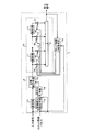
図1は、本発明の実施の形態1にかかる適応等化器の一構成例を示す図である。図1に示す適応等化器1は、その主要構成部として、自身の出力信号でもあり、信号の歪みや信号損失(減衰)を低減させた等化信号を出力するトランスバーサルフィルタ10と、トランスバーサルフィルタ10への入力信号を好適な信号状態に補正するための入力信号補正手段9と、トランスバーサルフィルタ10に付与する適切なタップ係数を推定するタップ係数推定手段14と、を備えている。また、各細部構成として、トランスバーサルフィルタ10は、第1の遅延器である(N−1)個(Nは自然数)の遅延器11、N個の乗算器12および1個の加算器13の各構成部を備え、入力信号補正手段9は、変調成分除去手段15、平均化手段16、第2の遅延器である遅延器17および位相補正手段18の各構成部を備えている。
FIG. 1 is a diagram of a configuration example of an adaptive equalizer according to the first embodiment of the present invention. An
つぎに、図1に示した実施の形態1にかかる適応等化器の動作について説明する。なお、図2は、本発明の実施の形態1にかかる適応等化器の動作タイミングチャートの一例を示す図であり、図3は、実施の形態1にかかる適応等化器の図2とは異なる動作タイミングチャートの一例を示す図である。また、以下では、図2や図3に示すように、スロットの先頭に既知系列であるユニークワード(UW)が付加されているデータフォーマットを持つ信号を受信していることを前提として説明する。 Next, the operation of the adaptive equalizer according to the first embodiment shown in FIG. 1 will be described. 2 is a diagram illustrating an example of an operation timing chart of the adaptive equalizer according to the first embodiment of the present invention. FIG. 3 is a diagram illustrating FIG. 2 of the adaptive equalizer according to the first embodiment. It is a figure which shows an example of a different operation | movement timing chart. The following description is based on the assumption that a signal having a data format in which a unique word (UW) that is a known sequence is added to the beginning of a slot is received as shown in FIGS.
図1に示す適応等化器1の入力信号補正手段9において、変調成分除去手段15は、スロット同期パルス(図2参照)を基準タイミングとして用いるとともに、入力信号がユニークワード(UW)の期間には、入力信号から変調成分を除去した無変調信号を出力する。ここで、入力信号と無変調信号は共に複素数の値を有する。
In the input signal correction means 9 of the
平均化手段16は、変調成分除去手段15と同様に、スロット同期パルスを基準タイミングとして用いるとともに、入力信号がユニークワード(UW)である期間内の予め決められた期間分だけ、変調成分除去手段15から出力される無変調信号の平均化を行うことにより、高SN比の無変調信号を出力する。なお、高SN比の無変調信号も、入力信号や無変調信号と同様に、複素数の値を有する信号である。
Similar to the modulation
遅延器17は、後述の位相補正手段18において、平均化手段16から出力される高SN比の無変調信号の偏角を、この偏角を算出するのに用いたスロットの先頭から補正できるように、入力信号を予め決められた時間だけ遅延させて出力する。
The
位相補正手段18は、遅延器17から出力される信号を、平均化手段16から出力される高SN比の無変調信号の偏角分だけ反対方向(偏角が進む場合には遅れる方向、遅れる場合には進む方向)に位相回転することにより、入力信号が持つキャリア位相を補正した信号を生成出力する。なお、位相補正手段18の出力信号も、上述の各出力信号と同様に、複素数の値を有する信号である。
The
一方、上述のようなNタップのトランスバーサルフィルタとして構成されたトランスバーサルフィルタ10は、入力信号補正手段9の位相補正手段18からの出力信号および遅延器11から出力される(N−1)個の遅延信号のそれぞれに、タップ係数推定手段14から出力される複素タップ係数{W0,n,W1,n,…,WN-2,n,WN-1,n}のそれぞれを個々に乗算し、全N個の乗算結果を全て加算した複素数の値を有する等化信号を生成出力する。
On the other hand, the
なお、タップ係数推定手段14は、従来の適応等化器と同様に、スロット同期パルスを基準タイミングとして用いるとともに、既知信号であるユニークワード(UW)が入力された場合に、トランスバーサルフィルタ10の出力信号である等化信号とレプリカ信号(等化器内部で保持する既知信号)との誤差信号を使用し、例えばLMS(Least Mean Square)アルゴリズムを用いて、トランスバーサルフィルタ10のタップ係数{W0,n,W1,n,…,WN-2,n,WN-1,n}を信号歪が小さくなるように更新する(nは離散時間であり、整数値である)。ただし、位相補正手段18で補正する位相量がスロット単位で変化するため、スロットの先頭でタップ係数{W0,n,W1,n,…,WN-2,n,WN-1,n}を予め決められた初期値にそれぞれセットすることが好ましい。
Note that the tap coefficient estimation means 14 uses the slot synchronization pulse as a reference timing as in the conventional adaptive equalizer, and when a unique word (UW) that is a known signal is input, An error signal between the equalized signal that is an output signal and a replica signal (a known signal held inside the equalizer) is used, and the tap coefficient {W of the
上述のように、実施の形態1の適応等化器1では、入力信号補正手段9の位相補正手段18にて位相補正を行うようにしているので、トランスバーサルフィルタ10から出力されたタップ係数推定手段14を動作させるための等化信号が、タップ係数推定手段14を動作させる最初のタイミング時から、レプリカ信号との誤差が小さくなるように制御されることとなり、入力信号のキャリア位相に依存することなく、短い既知系列であっても高精度に信号歪を補正することが可能となる。
As described above, in the
なお、上述の例では、タップ係数推定手段14におけるタップ係数推定アルゴリズムとして、LMSアルゴリズムを用いる場合を一例として説明したが、RLS(Recursive Least Square)等の他の逐次アルゴリズムを用いてタップ係数を更新してもよい。 In the above example, the case where the LMS algorithm is used as the tap coefficient estimation algorithm in the tap coefficient estimation means 14 has been described as an example. However, the tap coefficient is updated using another sequential algorithm such as RLS (Recursive Last Square). May be.
また、上述の説明では、タップ係数{W0,n,W1,n,…,WN-2,n,WN-1,n}を推定または更新するための入力信号として、ユニークワード(UW)が入力される場合について説明したが、図3に示すようなパイロットシンボル(PI)が挿入されているデータフォーマットが入力される場合には、ユニークワード(UW)が入力されるときばかりでなく、スロット途中に挿入された既知信号であるパイロットシンボル(PI)を利用してタップ係数を更新してもよい。なお、このようなパイロットシンボル(PI)を用いることにより、スロットの途中でもタップ係数を更新することが可能となり、時間変動が高速なフェージング伝送路においても、高精度に信号歪を補正することが可能となる。 In the above description, as an input signal for estimating or updating the tap coefficients {W 0, n , W 1, n ,..., W N−2, n , W N−1, n }, a unique word ( The case where a UW) is input has been described. However, when a data format in which a pilot symbol (PI) is inserted as shown in FIG. 3 is input, only when a unique word (UW) is input. Alternatively, the tap coefficient may be updated using a pilot symbol (PI) that is a known signal inserted in the middle of the slot. By using such a pilot symbol (PI), it is possible to update the tap coefficient even in the middle of the slot, and it is possible to correct the signal distortion with high accuracy even in a fading transmission line with a fast time variation. It becomes possible.
以上説明したように、この実施の形態の適応等化器によれば、既知系列を含む変調信号の入力時に、入力信号のキャリア位相を推定するとともに、推定したキャリア位相を打ち消すように位相補正した補正信号を出力するようにしているので、入力信号のキャリア位相に依存することなく、短い既知系列であっても高精度に信号歪を補正することが可能となる。 As described above, according to the adaptive equalizer of this embodiment, when a modulated signal including a known sequence is input, the carrier phase of the input signal is estimated and the phase correction is performed so as to cancel the estimated carrier phase. Since the correction signal is output, the signal distortion can be corrected with high accuracy even for a short known sequence without depending on the carrier phase of the input signal.
実施の形態2.
つぎに、実施の形態2では、例えばPSK変調やQAM変調された入力信号に対して、既知系列であるユニークワードから入力信号の振幅を推定し、この推定した振幅の分だけ振幅補正した信号に対して信号歪を補正することにより、短い既知系列で高精度に信号歪を補正する適応等化器の構成および動作について説明する。
Next, in the second embodiment, for example, for an input signal that has been subjected to PSK modulation or QAM modulation, the amplitude of the input signal is estimated from a unique word that is a known sequence, and the signal is amplitude-corrected by this estimated amplitude. On the other hand, the configuration and operation of an adaptive equalizer that corrects signal distortion with high accuracy with a short known sequence by correcting signal distortion will be described.
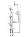
図4は、本発明の実施の形態2にかかる適応等化器の一構成例を示す図であり、実施の形態1の位相補正手段18の構成に代えて、振幅補正手段20を備えるように構成したものである。なお、その他の構成は、上述の実施の形態1と同様であり、実施の形態1と同一あるいは同等の構成については同一の符号を付してその説明を省略するとともに、以下では、実施の形態2の固有動作を中心に説明する。
FIG. 4 is a diagram illustrating a configuration example of an adaptive equalizer according to the second embodiment of the present invention, and includes an
図4に示す適応等化器1aの入力信号補正手段9aにおいて、振幅補正手段20は、遅延器17から出力される遅延入力信号を、平均化手段16から出力される高SN比の無変調信号の平均振幅の逆数に比例した所定値を乗算することにより、予め決められた平均振幅値に近くなるように振幅補正した信号(複素信号)を生成出力する。
In the input
上述のように、実施の形態2の適応等化器1aでは、入力信号補正手段9aの振幅補正手段20にて振幅補正を行うようにしているので、トランスバーサルフィルタ10から出力されたタップ係数推定手段14を動作させる等化信号が、タップ係数推定手段14を動作させる最初のタイミング時から、レプリカ信号との誤差が小さくなるように制御されることとなり、入力信号の信号振幅に依存することなく、短い既知系列であっても高精度に信号歪を補正することが可能となる。
As described above, in the
なお、図3に示すようなパイロットシンボル(PI)が挿入されているデータフォーマットが入力される場合には、実施の形態1の適応等化器と同様に、ユニークワード(UW)が入力されるときだけでなく、スロット途中に挿入された既知信号であるパイロットシンボル(PI)利用してタップ係数を更新してもよい。このようなパイロットシンボル(PI)を用いることにより、スロットの途中でもタップ係数を更新することが可能となり、時間変動が高速なフェージング伝送路においても、高精度に信号歪を補正することが可能となる。 When a data format in which pilot symbols (PI) are inserted as shown in FIG. 3 is input, a unique word (UW) is input as in the adaptive equalizer of the first embodiment. The tap coefficient may be updated using a pilot symbol (PI) which is a known signal inserted in the middle of the slot. By using such a pilot symbol (PI), it is possible to update the tap coefficient even in the middle of the slot, and it is possible to correct the signal distortion with high accuracy even in a fading transmission line with a fast time variation. Become.
なお、実施の形態1と同様に、タップ係数推定手段14におけるタップ係数推定アルゴリズムとして、LMSアルゴリズム以外の、例えばRLS等の他の逐次アルゴリズムを用いてタップ係数を更新してもよい。
As in the first embodiment, the tap coefficient may be updated using another sequential algorithm such as RLS other than the LMS algorithm as the tap coefficient estimation algorithm in the tap
以上説明したように、この実施の形態の適応等化器によれば、既知系列を含む変調信号の入力時に、入力信号の平均振幅を推定するとともに、推定した平均振幅に対して予め決められた平均振幅値に近くなるように振幅補正した補正信号を出力するようにしているので、入力信号の信号振幅に依存することなく、短い既知系列であっても高精度に信号歪を補正することが可能となる。 As described above, according to the adaptive equalizer of this embodiment, when a modulated signal including a known sequence is input, the average amplitude of the input signal is estimated and the estimated average amplitude is determined in advance. Since the correction signal whose amplitude is corrected to be close to the average amplitude value is output, the signal distortion can be corrected with high accuracy even for a short known series without depending on the signal amplitude of the input signal. It becomes possible.
実施の形態3.
つづいて、実施の形態3では、例えばPSK変調やQAM変調された入力信号に対して、既知系列であるユニークワードから入力信号のキャリア位相および振幅を推定し、この推定したキャリア位相および振幅の分だけそれぞれ位相および振幅を補正した信号に対して信号歪を補正することにより、短い既知系列で高精度に信号歪を補正する適応等化器の構成および動作について説明する。
Embodiment 3 FIG.
Subsequently, in Embodiment 3, for example, for a PSK modulated or QAM modulated input signal, the carrier phase and amplitude of the input signal are estimated from a unique word that is a known sequence, and the estimated carrier phase and amplitude are separated. Only the configuration and operation of the adaptive equalizer that corrects the signal distortion with high accuracy with a short known sequence by correcting the signal distortion with respect to the signal whose phase and amplitude are corrected respectively.
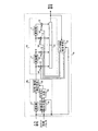
図5は、本発明の実施の形態3にかかる適応等化器の一構成例を示す図であり、実施の形態1の位相補正手段18および実施の形態2の振幅補正手段20の両機能を有する位相・振幅補正手段30を備えるように構成したものである。なお、その他の構成は実施の形態1または2と同様であり、それらと同一あるいは同等の構成については同一の符号を付してその説明を省略するとともに、以下では、実施の形態3の固有動作を中心に説明する。
FIG. 5 is a diagram showing a configuration example of an adaptive equalizer according to the third embodiment of the present invention. Both functions of the
図5に示す適応等化器1bの入力信号補正手段9bにおいて、位相・振幅補正手段30は、遅延器17から出力される遅延入力信号を、平均化手段16から出力される高SN比の無変調信号の平均振幅の逆数に比例した所定値を乗算することによる振幅補正と、平均化手段16から出力される高SN比の無変調信号の偏角分だけ反対方向に位相回転する位相補正と、を併せて実施した出力信号(複素信号)を生成出力する。
In the input
上述のように、実施の形態3の適応等化器1bでは、入力信号補正手段9bの位相・振幅補正手段30にて位相補正および振幅補正を行うようにしているので、トランスバーサルフィルタ10から出力されたタップ係数推定手段14を動作させる等化信号が、タップ係数推定手段14を動作させる最初のタイミング時からレプリカ信号との誤差が小さくなるように制御されることとなり、入力信号のキャリア位相や信号振幅に依存することなく、短い既知系列であっても高精度に信号歪を補正することが可能となる。
As described above, in the adaptive equalizer 1b of the third embodiment, the phase /
なお、図3に示すようなパイロットシンボル(PI)が挿入されているデータフォーマットを有する場合には、実施の形態1の適応等化器と同様に、ユニークワード(UW)が入力されるときだけでなく、スロット途中に挿入された既知信号であるパイロットシンボル(PI)を利用してタップ係数を更新してもよい。このようなパイロットシンボル(PI)を用いることにより、時間変動が高速なフェージング伝送路においても、より高精度に信号歪を補正することが可能となる。 In the case of having a data format in which a pilot symbol (PI) as shown in FIG. 3 is inserted, only when a unique word (UW) is input, as in the adaptive equalizer of the first embodiment. Instead, the tap coefficient may be updated using a pilot symbol (PI) which is a known signal inserted in the middle of the slot. By using such a pilot symbol (PI), it is possible to correct signal distortion with higher accuracy even in a fading transmission line with a fast time variation.
なお、実施の形態1,2と同様に、タップ係数推定手段14におけるタップ係数推定アルゴリズムとして、LMSアルゴリズム以外の、例えばRLS等の他の逐次アルゴリズムを用いてタップ係数を更新してもよい。
As in the first and second embodiments, the tap coefficient may be updated using another sequential algorithm such as RLS other than the LMS algorithm as the tap coefficient estimation algorithm in the tap
以上説明したように、この実施の形態の適応等化器によれば、既知系列を含む変調信号の入力時に、入力信号のキャリア位相および平均振幅を推定するとともに、推定したキャリア位相を打ち消すように位相補正し、かつ、推定した平均振幅に対して予め決められた平均振幅値に近くなるように振幅補正した補正信号を出力するようにしているので、入力信号のキャリア位相や信号振幅に依存することなく、短い既知系列であっても高精度に信号歪を補正することが可能となる。 As described above, according to the adaptive equalizer of this embodiment, when a modulated signal including a known sequence is input, the carrier phase and average amplitude of the input signal are estimated, and the estimated carrier phase is canceled out. Since a correction signal is output that is phase-corrected and amplitude-corrected so that the estimated average amplitude is close to a predetermined average amplitude value, it depends on the carrier phase and signal amplitude of the input signal. Therefore, signal distortion can be corrected with high accuracy even for a short known sequence.
実施の形態4.
つづいて、実施の形態4では、実施の形態1〜3の任意の適応等化器を具備し、外部から入力されるタップ係数制御信号(2値以上の種類の値を持つ)に基づいて、実際に使用するタップ数を可変とし、使用しないタップのタップ係数は零に固定する一方で、使用するタップ係数を伝送路に適したタップ数で適応動作させることにより、より短い既知系列でより高精度に信号歪を補正する適応等化器の構成および動作について説明する。
Embodiment 4 FIG.
Subsequently, in the fourth embodiment, based on the tap coefficient control signal (having two or more types of values) input from the outside, including any of the adaptive equalizers of the first to third embodiments, By making the number of taps actually used variable and fixing tap coefficients of unused taps to zero, the tap coefficients used are adaptively operated with the number of taps suitable for the transmission path, so that the higher the length of a shorter known sequence, the higher the number of taps used. The configuration and operation of an adaptive equalizer that corrects signal distortion with high accuracy will be described.
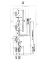
図6は、本発明の実施の形態4にかかる適応等化器の一構成例を示す図であり、図1に示した実施の形態1の適応等化器1において、タップ係数推定手段40に外部からのタップ係数制御信号を入力するようにして、実際に使用するタップ数を可変にできるように変更したものである。なお、その他の構成は実施の形態1と同様であり、実施の形態1と同一あるいは同等の構成については同一の符号を付してその説明を省略するとともに、以下では、実施の形態4の固有動作を中心に説明する。
FIG. 6 is a diagram showing a configuration example of an adaptive equalizer according to the fourth embodiment of the present invention. In the
図6において、適応等化器1cのタップ係数推定手段40には、外部からのタップ係数制御信号が入力される。タップ係数制御信号が入力されたタップ係数推定手段40は、予め決定されているタップのタップ係数を常に零にするとともに、使用するタップ係数のみを、例えばLMSアルゴリズムを用いて更新するようにする。 In FIG. 6, an external tap coefficient control signal is input to the tap coefficient estimation means 40 of the adaptive equalizer 1c. The tap coefficient estimating means 40 to which the tap coefficient control signal is input always sets the tap coefficient of the tap determined in advance to zero, and updates only the tap coefficient to be used using, for example, the LMS algorithm.
上述のように、実施の形態4の適応等化器1cでは、伝送路の遅延広がりに適したタップ係数制御信号の値を外部から設定し、使用しないタップのタップ係数を零にして、動作させるタップ数を適切に制御するようにしているので、実施の形態1の適応等化器と比較して、より短い既知系列でより高精度に信号歪を補正することが可能となる。 As described above, the adaptive equalizer 1c according to the fourth embodiment operates by setting the tap coefficient control signal value suitable for the delay spread of the transmission path from the outside and setting the tap coefficients of unused taps to zero. Since the number of taps is appropriately controlled, signal distortion can be corrected with higher accuracy with a shorter known sequence as compared with the adaptive equalizer of the first embodiment.
なお、実施の形態4では、外部から入力されるタップ係数制御信号に基づいて、実際に使用するタップ数を可変とするなどの構成を実施の形態1に適用する例を一例として説明したが、実施の形態2,3のそれぞれに適用することもでき、それらの各実施の形態に固有な効果も得ることができる。 In the fourth embodiment, an example in which the configuration in which the number of taps actually used is variable based on a tap coefficient control signal input from the outside is applied to the first embodiment is described as an example. The present invention can also be applied to each of the second and third embodiments, and effects unique to the respective embodiments can also be obtained.
また、タップ係数推定手段40では、LMSアルゴリズムを用いる場合を一例として説明したが、例えばRLS等の他の逐次アルゴリズムを用いてタップ係数を更新してもよい。
Further, the tap
以上説明したように、この実施の形態の適応等化器によれば、外部から入力されるタップ係数制御信号に基づき、使用しないタップのタップ係数を零にして使用するタップのタップ数を可変制御するようにしているので、より短い既知系列でより高精度に信号歪を補正することが可能となり、また、処理速度を向上させることができる。 As described above, according to the adaptive equalizer of this embodiment, the tap number of taps to be used is variably controlled by setting the tap coefficient of unused taps to zero based on an externally input tap coefficient control signal. As a result, signal distortion can be corrected with higher accuracy using a shorter known sequence, and the processing speed can be improved.
実施の形態5.
つついて、実施の形態5では、タップ係数制御信号(2値以上の種類の値を持つ)を外部から入力する代わりに、入力信号に基づいて伝送路推定手段で推定されたタップ係数制御信号を用いる適応等化器の構成および動作について説明する。なお、本実施の形態においても、実施の形態4と同様に、実際に使用するタップ数を可変とし、使用しないタップのタップ係数は零に固定する一方で、使用するタップ係数を伝送路に適したタップ数で適応動作させることにより、より短い既知系列でより高精度に信号歪を補正する機能が具備される。
Embodiment 5 FIG.
On the other hand, in the fifth embodiment, instead of inputting a tap coefficient control signal (having two or more kinds of values) from the outside, the tap coefficient control signal estimated by the transmission path estimation means based on the input signal is used. The configuration and operation of the adaptive equalizer used will be described. In the present embodiment, as in the fourth embodiment, the number of taps that are actually used is variable and the tap coefficients of unused taps are fixed to zero, while the tap coefficients that are used are suitable for the transmission line. By performing the adaptive operation with the number of taps, a function of correcting the signal distortion with higher accuracy with a shorter known sequence is provided.
図7は、本発明の実施の形態5にかかる適応等化器の一構成例を示す図であり、実施の形態4の適応等化器の構成において、タップ係数推定手段40へのタップ係数制御信号を入力信号に基づいて生成出力する伝送路推定手段50を備えるように構成したものである。なお、その他の構成は、上述の実施の形態4と同様であり、実施の形態4と同一あるいは同等の構成については同一の符号を付してその説明を省略するとともに、以下では、実施の形態5の固有動作を中心に説明する。
FIG. 7 is a diagram illustrating a configuration example of an adaptive equalizer according to the fifth embodiment of the present invention. In the configuration of the adaptive equalizer according to the fourth embodiment, tap coefficient control to the tap
図7に示す適応等化器1dにおいて、伝送路推定手段50は、スロット同期パルスを基準タイミングとして用いるとともに、既知信号であるユニークワード(UW)が入力される場合に、入力信号に対してマッチドフィルタ等を用いた相関演算を行うことにより、伝送路の遅延広がりを推定する。そして、推定した遅延広がりに適したタップ係数制御信号の値を選択して出力する。 In the adaptive equalizer 1d shown in FIG. 7, the transmission path estimation means 50 uses the slot synchronization pulse as a reference timing, and matches the input signal when a unique word (UW) that is a known signal is input. By performing correlation calculation using a filter or the like, the delay spread of the transmission path is estimated. Then, a tap coefficient control signal value suitable for the estimated delay spread is selected and output.
さらに、タップ係数推定手段40は、実施の形態4と同様に、タップ係数制御信号により予め決定されているタップのタップ係数を常に零に固定する一方で、使用するタップ係数のみを、例えばLMSアルゴリズムを用いて更新する。 Further, the tap coefficient estimation means 40, as in the fourth embodiment, always fixes the tap coefficient of the tap previously determined by the tap coefficient control signal to zero while only using the tap coefficient to be used, for example, the LMS algorithm. Update using.
上述のように、実施の形態5の適応等化器1dでは、入力信号に基づいて推定した遅延広がりに適したタップ係数制御信号の値を算出し、算出したタップ係数制御信号に基づいて使用しないタップのタップ係数を零にして、動作させるタップ数を適切に制御するようにしているので、伝送路の遅延広がりが変動する場合であっても、短い既知系列で高精度に信号歪を補正することが可能となる。 As described above, the adaptive equalizer 1d according to the fifth embodiment calculates the value of the tap coefficient control signal suitable for the delay spread estimated based on the input signal, and does not use it based on the calculated tap coefficient control signal. Since the tap coefficient of taps is set to zero and the number of taps to be operated is controlled appropriately, signal distortion can be corrected with high accuracy with a short known sequence even when the delay spread of the transmission path fluctuates. It becomes possible.
なお、タップ係数推定手段40では、LMSアルゴリズムを用いる場合を説明したが、他の実施の形態と同様に他の逐次アルゴリズムを用いてタップ係数を更新してもよい。
Although the tap
また、伝送路推定手段50では、既知信号であるユニークワード(UW)に対して相関演算を求めることにより遅延広がりを推定する手法を示したが、入力信号から他の遅延広がりを推定する手法を用いてもよく、入力信号から適切にタップ係数制御信号を生成できればよい。 In addition, although the transmission path estimation means 50 has shown a technique for estimating a delay spread by obtaining a correlation operation for a unique word (UW) that is a known signal, a technique for estimating another delay spread from an input signal is shown. The tap coefficient control signal may be generated appropriately from the input signal.
また、図8は、本発明の実施の形態5にかかる適応等化器の図7とは異なる他の構成例を示す図である。図7に示す伝送路推定手段50では、タップ係数制御信号を入力信号に基づいて生成する手法を示したが、図8に示すように、タップ係数推定手段40から出力される過去のタップ係数{W0,n,W1,n,…,WN-2,n,WN-1,n}に基づいてタップ係数制御信号を生成するようにしてもよい。この場合、図7に示した適応等化器1dと同様に、伝送路の遅延広がりが変動する場合であっても、短い既知系列で高精度に信号歪を補正するという効果が得られる。さらに、図8に示す適応等化器1eでは、伝送路推定手段50aおける相関演算が不要になるため、回路規模の削減が可能であるという効果をも得られる。 Moreover, FIG. 8 is a figure which shows the other structural example different from FIG. 7 of the adaptive equalizer concerning Embodiment 5 of this invention. In the transmission path estimation means 50 shown in FIG. 7, the method of generating the tap coefficient control signal based on the input signal has been shown, but as shown in FIG. 8, the past tap coefficients {output from the tap coefficient estimation means 40 { Tap coefficient control signals may be generated based on W 0, n , W 1, n ,..., W N−2, n , W N−1, n }. In this case, similar to the adaptive equalizer 1d shown in FIG. 7, even when the delay spread of the transmission path varies, the effect of correcting the signal distortion with high accuracy with a short known sequence can be obtained. Further, in the adaptive equalizer 1e shown in FIG. 8, since the correlation calculation in the transmission path estimation means 50a is not required, an effect that the circuit scale can be reduced can be obtained.
以上説明したように、この実施の形態の適応等化器によれば、自身内部で生成したタップ係数制御信号に基づき、使用しないタップのタップ係数を零にして使用するタップのタップ数を可変制御するようにしているので、伝送路の遅延広がりが変動する場合であっても、短い既知系列で高精度に信号歪を補正することが可能となる。 As described above, according to the adaptive equalizer of this embodiment, based on the tap coefficient control signal generated inside itself, the tap coefficient of taps to be used is variably controlled by setting the tap coefficient of unused taps to zero. Thus, even when the delay spread of the transmission path varies, it is possible to correct the signal distortion with high accuracy with a short known sequence.
また、この実施の形態の適応等化器によれば、タップ係数制御信号を過去のタップ係数に基づいて生成出力することもできるので、タップ係数制御信号の生成に必要な相関演算処理の一部または全部を不要とすることができ、回路規模をより低減させることができる。 Further, according to the adaptive equalizer of this embodiment, since the tap coefficient control signal can be generated and output based on the past tap coefficient, a part of the correlation calculation processing necessary for generating the tap coefficient control signal is also provided. Alternatively, all of them can be made unnecessary, and the circuit scale can be further reduced.
実施の形態6.
つづいて、実施の形態6では、例えばPSK変調やQAM変調された入力信号に対して、実施の形態1〜5の任意の適応等化器を用いることにより、短い既知系列の使用が要請される無線通信システムにおいて、高品質な復調データの出力を可能とする受信装置の構成および動作について説明する。
Embodiment 6 FIG.
Subsequently, in the sixth embodiment, for example, the use of a short known sequence is required by using any of the adaptive equalizers of the first to fifth embodiments for an input signal subjected to PSK modulation or QAM modulation. A configuration and operation of a receiving apparatus that enables output of high-quality demodulated data in a wireless communication system will be described.
図9は、本発明の実施の形態6にかかる受信装置の一構成例を示す図である。図9に示す受信装置は、図1に示した実施の形態1にかかる適応等化器1を中心に、適応等化器1の入力側には、受信アンテナ60に接続される準同期検波手段61と、準同期検波手段61の利得を制御するためのゲイン制御信号を出力する自動ゲイン制御(AGC:Automatic Gain Control)手段62と、準同期検波手段61の出力を入力信号とするビットタイミング再生(BTR:Bit Timing Recovery)手段63と、ビットタイミング再生手段63の出力を入力信号とするスロット同期手段64および自動周波数制御(AFC:Automatic Frequency Control)手段65と、が具備されるとともに、適応等化器1の出力側には、データ判定手段66が具備される。なお、スロット同期手段64の出力は、自動周波数制御手段65、適応等化器1およびデータ判定手段66のそれぞれに入力される。
FIG. 9 is a diagram of a configuration example of a receiving apparatus according to the sixth embodiment of the present invention. The receiving apparatus shown in FIG. 9 has a quasi-synchronous detection means connected to the receiving
つぎに、図9に示した実施の形態6にかかる受信装置の動作について説明する。図9において、準同期検波手段61は、受信アンテナ60で受信した信号に対して、準同期検波および予め決められたレートでのアナログ・ディジタル変換を行ったベースバンド信号(複素信号)を出力する。また、準同期検波手段61は、後述の自動ゲイン制御手段62から出力されるゲイン制御信号に基づいて受信信号のゲイン補正も行う。
Next, the operation of the receiving apparatus according to the sixth embodiment shown in FIG. 9 will be described. In FIG. 9, the quasi-synchronous detection means 61 outputs a baseband signal (complex signal) obtained by performing quasi-synchronous detection and analog-digital conversion at a predetermined rate on the signal received by the receiving
自動ゲイン制御手段62は、ベースバンド信号の電力を観測し、観測した電力値が予め決められた値になるようにゲイン制御信号を生成する。ビットタイミング再生手段63は、ベースバンド信号からナイキスト点となるタイミングの推定を行い、このナイキスト点のタイミングに同期し、かつ、シンボルレートのM倍(Mは自然数)のレートで再サンプリングされたベースバンド信号である再生ベースバンド信号を出力する。 The automatic gain control means 62 observes the power of the baseband signal and generates a gain control signal so that the observed power value becomes a predetermined value. The bit timing reproduction means 63 estimates the timing of the Nyquist point from the baseband signal, is synchronized with the timing of the Nyquist point, and is resampled at a rate M times the symbol rate (M is a natural number). A playback baseband signal that is a band signal is output.
スロット同期手段64は、再生ベースバンド信号とユニークワード(UW)のレプリカ信号との間で相関演算を行い、この相関値が予め決められた閾値より大きくなるときのタイミングでスロット同期パルスを生成する。 The slot synchronization means 64 performs a correlation operation between the reproduction baseband signal and the unique word (UW) replica signal, and generates a slot synchronization pulse at a timing when the correlation value becomes larger than a predetermined threshold value. .
自動周波数制御手段65は、ビットタイミング再生手段63から出力された再生ベースバンド信号の所定期間の位相回転量に基づいて周波数偏差を推定し、この再生ベースバンド信号に対して、推定した周波数偏差を打ち消すように位相回転を行うことにより、周波数偏差補正ベースバンド信号(複素信号)を生成して適応等化器1に出力する。なお、ユニークワード(UW)やパイロットシンボル(PI)等の既知信号を処理する場合には、自動周波数制御手段65は、スロット同期手段64から出力されるスロット同期パルスを基準タイミングとして、これらの既知信号のレプリカを用いて変調成分除去を行うことにより、高精度に周波数偏差を推定するようにしてもよい。
The automatic frequency control means 65 estimates the frequency deviation based on the phase rotation amount of the reproduction baseband signal output from the bit timing reproduction means 63 for a predetermined period, and calculates the estimated frequency deviation for this reproduction baseband signal. By performing phase rotation so as to cancel, a frequency deviation corrected baseband signal (complex signal) is generated and output to the
適応等化器1は、実施の形態1で示したものであり、周波数偏差補正ベースバンド信号を入力信号として適応等化を行うことにより、高精度な等化信号(複素信号)を生成して出力する。
The
データ判定手段66は、適応等化器1から出力される高精度な等化信号に対して、変調方式に対応した判定方式を用いてデータ復調を行うことにより、高品質な復調データを出力する。
The
上述のように、実施の形態6の受信装置では、実施の形態1で示した適応等化器1を適用することで、高精度な等化信号を生成することができ、データ判定手段66にて高品質な復調データを生成することが可能となる。
As described above, in the receiving apparatus according to the sixth embodiment, by applying the
また、図10は、本発明の実施の形態6にかかる受信装置の図9とは異なる他の構成例を示す図である。図9に示す受信装置では、適応等化器1から出力される等化信号をデータ判定手段66に直接的に入力したが、図10に示すように、等化信号をキャリア再生手段67に入力した後にデータ判定手段66に入力してもよい。この場合、適応等化器1が動作していない場合であってもキャリア再生手段67でキャリア位相の追従を行うことができるため、より高品質な復調データを得ることが可能となる。
FIG. 10 is a diagram illustrating another configuration example different from FIG. 9 of the receiving apparatus according to the sixth embodiment of the present invention. In the receiving apparatus shown in FIG. 9, the equalized signal output from the
なお、実施の形態6では、実施の形態1で示した適応等化器1を用いて高品質な復調データを生成する受信装置の構成について説明したが、適応等化器1の代わりに、実施の形態2〜5で示した適応等化器1a〜1eを適用することもでき、本実施の形態と同様の効果を併せ持つことができる。
In the sixth embodiment, the configuration of a receiving apparatus that generates high-quality demodulated data using the
以上説明したように、この実施の形態の受信装置によれば、実施の形態1〜5で示した適応等化器を用いて構成しているので、より高精度な等化信号を用いて、高品質な復調データを出力することができる。
As described above, according to the receiving apparatus of this embodiment, since it is configured using the adaptive equalizer shown in
また、この実施の形態の受信装置によれば、等化信号を復調する前にキャリア再生手段にてキャリア位相の追従を行うこととすれば、さらに高品質な復調データを得ることができる。 Further, according to the receiving apparatus of this embodiment, if the carrier phase is followed by the carrier reproducing means before demodulating the equalized signal, higher quality demodulated data can be obtained.
以上のように、本発明にかかる適応等化器および受信装置は、短い既知系列で高精度に信号歪を補正する適応等化器および受信装置として有用である。 As described above, the adaptive equalizer and receiving apparatus according to the present invention are useful as an adaptive equalizer and receiving apparatus that correct signal distortion with high accuracy with a short known sequence.
1,1a,1b,1c,1d,1e 適応等化器
9,9a,9b 入力信号補正手段
10 トランスバーサルフィルタ
11,17 遅延器
12 乗算器
13 加算器
14 タップ係数推定手段
15 変調成分除去手段
16 平均化手段
18 位相補正手段
20 振幅補正手段
30 位相・振幅補正手段
40 タップ係数推定手段
50,50a 伝送路推定手段
60 受信アンテナ
61 準同期検波手段
62 自動ゲイン制御手段
63 ビットタイミング再生手段
64 スロット同期手段
65 自動周波数制御手段
66 データ判定手段
67 キャリア再生手段
1, 1a, 1b, 1c, 1d, 1e
Claims (10)
前記入力信号補正手段の出力信号に対して、予め推定されたタップ係数を個々のタップごとに重み付けした後の加算結果を等化信号として出力するトランスバーサルフィルタと、
所定の同期信号を基準タイミングとして用いるとともに、前記トランスバーサルフィルタの出力信号である等化信号と該既知信号のレプリカ信号との誤差信号に対して、所定の逐次タップ係数推定アルゴリズムを用いて前記タップ係数の更新を行うタップ係数推定手段と、
を備えたことを特徴とする適応等化器。 For a modulated signal having a data format including a known signal, a predetermined parameter of the modulated signal including the known signal is estimated when the modulated signal is input, and a correction signal corrected based on the estimated predetermined parameter is output. Input signal correction means;
A transversal filter that outputs, as an equalized signal, an addition result after weighting the tap coefficient estimated in advance for each individual tap with respect to the output signal of the input signal correcting means;
The tap signal is used by using a predetermined sequential tap coefficient estimation algorithm for an error signal between an equalization signal that is an output signal of the transversal filter and a replica signal of the known signal, using a predetermined synchronization signal as a reference timing. Tap coefficient estimation means for updating the coefficient;
An adaptive equalizer characterized by comprising:
前記タップ係数推定手段は、前記伝送路推定手段から出力されるタップ係数制御信号に基づき、使用しないタップのタップ係数を零にして使用するタップのタップ数を可変制御することを特徴とする請求項1〜4のいずれか一つに記載の適応等化器。 Further comprising transmission path estimation means for estimating the delay spread of the transmission path from the input signal and generating and outputting a tap coefficient control signal corresponding to the estimated delay spread;
The tap coefficient estimating means variably controls the number of taps to be used with zero tap coefficients of unused taps based on a tap coefficient control signal output from the transmission path estimating means. The adaptive equalizer as described in any one of 1-4.
前記タップ係数推定手段では、前記ユニークワードの入力時に加えて、前記パイロットシンボルの入力時にもタップ係数が更新されることを特徴とする請求項1〜7のいずれか一つに記載の適応等化器。 The data format of the known signal includes a unique word and a pilot symbol,
The adaptive equalization according to any one of claims 1 to 7, wherein the tap coefficient estimating means updates the tap coefficient when the pilot symbol is input in addition to the input of the unique word. vessel.
前記再生ベースバンド信号と前記既知信号のレプリカ信号との間で相関演算を行い、該相関演算を行った相関値が予め決められた閾値より大となるタイミングで同期パルスを生成する同期手段と、
前記再生ベースバンド信号が入力され、前記同期手段から出力される同期パルスに基づいて該再生ベースバンド信号に等化処理を施した等化信号を出力する請求項1〜8のいずれか一つに記載の適応等化器と、
前記等化信号が入力され、前記変調信号の変調方式に応ずる所定の判定方式に基づいてデータ復調を行った復調データを出力するデータ判定手段と、
を備えたことを特徴とする受信装置。 A modulated signal having a data format including a known signal is received, a timing to be a Nyquist point is estimated from a baseband signal obtained by detecting the modulated signal, and the symbol rate is synchronized with the timing of the Nyquist point. A bit timing reproduction means for generating a reproduction baseband signal resampled at a rate of M times (M is a natural number);
Synchronizing means for performing a correlation operation between the reproduction baseband signal and the replica signal of the known signal, and generating a synchronization pulse at a timing when the correlation value obtained by performing the correlation operation is greater than a predetermined threshold value;
9. The reproduction baseband signal is input, and an equalized signal obtained by performing equalization processing on the reproduction baseband signal based on a synchronization pulse output from the synchronization unit is output. The adaptive equalizer described, and
A data determination unit that receives the equalized signal and outputs demodulated data obtained by performing data demodulation based on a predetermined determination method according to a modulation method of the modulation signal;
A receiving apparatus comprising:
Priority Applications (1)
| Application Number | Priority Date | Filing Date | Title |
|---|---|---|---|
| JP2006016814A JP2007201729A (en) | 2006-01-25 | 2006-01-25 | Adaptive equalizer and receiver |
Applications Claiming Priority (1)
| Application Number | Priority Date | Filing Date | Title |
|---|---|---|---|
| JP2006016814A JP2007201729A (en) | 2006-01-25 | 2006-01-25 | Adaptive equalizer and receiver |
Publications (1)
| Publication Number | Publication Date |
|---|---|
| JP2007201729A true JP2007201729A (en) | 2007-08-09 |
Family
ID=38455872
Family Applications (1)
| Application Number | Title | Priority Date | Filing Date |
|---|---|---|---|
| JP2006016814A Pending JP2007201729A (en) | 2006-01-25 | 2006-01-25 | Adaptive equalizer and receiver |
Country Status (1)
| Country | Link |
|---|---|
| JP (1) | JP2007201729A (en) |
Cited By (5)
| Publication number | Priority date | Publication date | Assignee | Title |
|---|---|---|---|---|
| JP2009094942A (en) * | 2007-10-11 | 2009-04-30 | Fujitsu Microelectronics Ltd | Receiving apparatus and receiving method |
| JP2010118817A (en) * | 2008-11-12 | 2010-05-27 | Nec Corp | Adaptive equalizer and tap-coefficient control method |
| JP2010136363A (en) * | 2008-11-12 | 2010-06-17 | Intel Corp | Decision feedback equalizer under portable environment |
| JP2011151755A (en) * | 2010-01-25 | 2011-08-04 | Fujitsu Ltd | Adaptive equalizer and adaptive equalization method |
| JP2015207816A (en) * | 2014-04-17 | 2015-11-19 | 富士通株式会社 | Receiver, reception method, and wireless communication system |
-
2006
- 2006-01-25 JP JP2006016814A patent/JP2007201729A/en active Pending
Cited By (7)
| Publication number | Priority date | Publication date | Assignee | Title |
|---|---|---|---|---|
| JP2009094942A (en) * | 2007-10-11 | 2009-04-30 | Fujitsu Microelectronics Ltd | Receiving apparatus and receiving method |
| US8457189B2 (en) | 2007-10-11 | 2013-06-04 | Fujitsu Semiconductor Limited | Receiving apparatus having equalizer, and receiving method |
| JP2010118817A (en) * | 2008-11-12 | 2010-05-27 | Nec Corp | Adaptive equalizer and tap-coefficient control method |
| JP2010136363A (en) * | 2008-11-12 | 2010-06-17 | Intel Corp | Decision feedback equalizer under portable environment |
| US8526486B2 (en) | 2008-11-12 | 2013-09-03 | Intel Corporation | Decision feedback equalizer for portable environments |
| JP2011151755A (en) * | 2010-01-25 | 2011-08-04 | Fujitsu Ltd | Adaptive equalizer and adaptive equalization method |
| JP2015207816A (en) * | 2014-04-17 | 2015-11-19 | 富士通株式会社 | Receiver, reception method, and wireless communication system |
Similar Documents
| Publication | Publication Date | Title |
|---|---|---|
| JP4240365B2 (en) | Carrier phase recovery system for adaptive burst modem and link hopping wireless networks | |
| EP0684708B1 (en) | Adaptive equalizer | |
| US7031405B1 (en) | Carrier phase estimation based on single-axis constant modulus cost criterion and Bussgang criteria | |
| EP0430481A2 (en) | Method and apparatus for diversity reception of time-dispersed signals | |
| JPH10271051A (en) | Transmitter-receiver with two-way equalization | |
| JP6540295B2 (en) | Adaptive equalization circuit, digital coherent receiver and adaptive equalization method | |
| CN110832817A (en) | Transmitter, receiver and corresponding method | |
| JP2007201729A (en) | Adaptive equalizer and receiver | |
| TW201312981A (en) | Timing recovery module and timing recovery method | |
| JP6746030B2 (en) | Receiver, received signal processing method, control circuit and storage medium | |
| JP4649381B2 (en) | Wraparound canceller | |
| EP3259890B1 (en) | Local oscillator phase noise tracking for single carrier transmission | |
| JP2010050834A (en) | Ofdm digital signal equalizer, equalization method, and repeater device | |
| JP4822946B2 (en) | Adaptive equalizer | |
| EP1259040A2 (en) | Equalisation for QAM signals | |
| JP2000232494A (en) | Signal carrier recovery processing method | |
| JP4985535B2 (en) | Demodulator circuit | |
| JP2003283385A (en) | Equalizer | |
| JP2009100357A (en) | Waveform equalizer and its control method | |
| JPH06268540A (en) | Viterbi equalizing method | |
| JP2007235407A (en) | Adaptive equalizer and communication apparatus | |
| JPH11103326A (en) | Demodulator | |
| JP2002290294A (en) | Waveform equalizer, frequency offset compensation method, program, recording medium, mobile station wireless unit using the waveform equalizer, base station wireless unit, and mobile communication system | |
| JP4285136B2 (en) | Feedback control apparatus and method | |
| JP2004172738A (en) | Demodulation method and apparatus |