JP2007201239A - Etching foil for electrolytic capacitor and method for manufacturing positive electrode foil using it - Google Patents
Etching foil for electrolytic capacitor and method for manufacturing positive electrode foil using it Download PDFInfo
- Publication number
- JP2007201239A JP2007201239A JP2006018909A JP2006018909A JP2007201239A JP 2007201239 A JP2007201239 A JP 2007201239A JP 2006018909 A JP2006018909 A JP 2006018909A JP 2006018909 A JP2006018909 A JP 2006018909A JP 2007201239 A JP2007201239 A JP 2007201239A
- Authority
- JP
- Japan
- Prior art keywords
- foil
- etching
- positive electrode
- electrolytic capacitor
- pits
- Prior art date
- Legal status (The legal status is an assumption and is not a legal conclusion. Google has not performed a legal analysis and makes no representation as to the accuracy of the status listed.)
- Pending
Links
Images

Abstract
Description
本発明は、電解コンデンサ用エッチング箔とそれを用いた陽極箔の製造方法に関する。 The present invention relates to an etching foil for electrolytic capacitors and a method for producing an anode foil using the same.
一般にアルミニウム電解コンデンサ用陽極箔は、単位面積当たりの静電容量を高めるため、電気化学的または化学的にエッチング処理することにより、エッチングピットを形成したエッチング箔の表面に、化成により酸化皮膜を設けたものである(例えば、特開平3-109711号公報、特開平10-256096号公報等)。エッチングピットは、陽極箔の表裏面に貫通するもの(以下、貫通ピットという)と、貫通しないもの(以下、不貫通ピットという)とがある。特に、貫通タイプの陽極箔は、貫通ピットを電解液が浸透し、陰極箔へのイオン伝導が行われるため、陽極箔を2枚重ねてダブルアノードとして使用できる反面、不貫通タイプの陽極箔と異なり、厚さ方向の中心部に芯と呼ばれる地金部分が少ないため、機械的強度が弱く、化成処理したり、陽極箔を複数枚積層して接続したりする際に、箔割れしたり切断してしまう。
このため、従来は、機械的強度を維持するために、ピット数を少なくしたり、箔の側縁部にエッチングされない帯状の未エッチング部を設けたりしていた。また、特開平2000-231582号公報では、エッチングする前に任意の形状で表裏またはどちらか一方をマスキングし、部分的にエッチングピットの発生を抑制し、未エッチング部分を設け接続部とする方法もある。
In general, an anode foil for an aluminum electrolytic capacitor is provided with an oxide film by chemical conversion on the surface of an etching foil in which etching pits have been formed by electrochemically or chemically etching in order to increase the capacitance per unit area. (For example, JP-A-3-109711, JP-A-10-256096, etc.). The etching pits include those that penetrate the front and back surfaces of the anode foil (hereinafter referred to as through pits) and those that do not penetrate (hereinafter referred to as non-through pits). In particular, the penetration type anode foil allows penetration of the electrolyte through the penetration pits and ion conduction to the cathode foil, so that two anode foils can be used as a double anode, but on the other hand, In contrast, since there are few metal parts called cores in the center in the thickness direction, mechanical strength is weak, and when performing chemical conversion treatment or stacking and connecting multiple anode foils, foil cracking or cutting Resulting in.
For this reason, conventionally, in order to maintain the mechanical strength, the number of pits is reduced, or a strip-shaped unetched portion that is not etched is provided on the side edge of the foil. Japanese Patent Laid-Open No. 2000-231582 also discloses a method of masking the front and back or either side with an arbitrary shape before etching, partially suppressing the generation of etching pits, and providing an unetched portion as a connection portion. is there.
しかしながら、ピット数を少なくして貫通ピットが形成されていない部分を多く残すと、単位面積当たりで得られる静電容量が制限されるため、大容量化を図る上で障害になるという問題があった。陽極箔の側縁部に帯状の未エッチング部を設ける場合も、それだけ有効表面積が減少するため、大容量化を図る上で障害になる。
また、特開平2000-231582号公報に記載された方法は、エッチング前にあらかじめマスキングを必要とし、さらにエッチング工程内でマスキング塗布部分を除去する必要があるため、マスキング工程と、マスキング塗布部分の除去工程にて発生する使用済み塗布剤の処理の工程が増えるという問題があった。
However, if the number of pits is reduced to leave a large number of portions where no through pits are formed, the capacitance obtained per unit area is limited, which is an obstacle to increase the capacity. It was. Even when a strip-like unetched portion is provided on the side edge of the anode foil, the effective surface area is reduced accordingly, which is an obstacle to increasing the capacity.
In addition, the method described in Japanese Patent Application Laid-Open No. 2000-231582 requires masking in advance before etching, and it is necessary to remove the masking application part in the etching process. There has been a problem in that the number of processing steps for the used coating agent generated in the process increases.
本発明は上記した従来の問題を解決するためになされたもので、その目的とするところは、陽極箔の一部に、結果的に機械的強度が強化された接続用の圧縮部を設けるという簡単な構造で、静電容量を損なうことなく、複数の陽極箔または陽極箔とリード端子等とを確実に接続することができるようにした積層型電解コンデンサ用陽極箔を提供することにある。
また、この構造とすることで、積層型だけでなく、巻回型の電解コンデンサにおいても、適用が可能である。
The present invention has been made in order to solve the above-described conventional problems, and the object of the present invention is to provide a compression part for connection with enhanced mechanical strength as a result in part of the anode foil. It is an object of the present invention to provide an anode foil for a multilayer electrolytic capacitor having a simple structure and capable of reliably connecting a plurality of anode foils or anode foils to lead terminals and the like without impairing electrostatic capacity.
Further, by adopting this structure, the present invention can be applied not only to the multilayer type but also to the wound type electrolytic capacitor.
エッチングピットを有する電解コンデンサ用エッチング箔において、箔どうしまたはその他必要な部材を接続する接続用の圧縮部分を設けた電解コンデンサ用エッチング箔を提供するものである。
また、電解コンデンサ用箔にエッチングピットを設ける第1工程と、前記箔に接続用の圧縮部分を設ける第2工程と、前記箔の表面を化成する第3工程とを備えた、電解コンデンサ用陽極箔の製造方法を提供するものである。
An electrolytic capacitor etching foil having an etching pit, which is provided with a compression portion for connection for connecting foils or other necessary members.
An electrolytic capacitor anode comprising a first step of providing an etching pit on the electrolytic capacitor foil, a second step of providing a compressed portion for connection to the foil, and a third step of forming the surface of the foil. A method for producing a foil is provided.
本発明に係る接続用部分圧縮を施した陽極箔を用いれば、エッチング工程により粗面化されることによる形成された微細な空間が、圧縮により押しつぶされることによって機械的強度を増大することができる。
また、上記微細な空間が圧縮されることにより、その後の製造工程である化成工程において、上記微細な空間内部の化成皮膜形成が抑制されるので、陽極箔の脆くなる部分が減少し、機械的強度を維持することができる。
これらにより、コールドウェルド法(圧着法)などによって、複数の陽極箔を積層して接続する際や、陽極箔とリード端子等とを接続する際に、接続部において、箔割れしたり、切断してしまうことを防止することができる。
If the anode foil subjected to the partial compression for connection according to the present invention is used, the mechanical strength can be increased by crushing the fine space formed by the roughening by the etching process. .
In addition, since the fine space is compressed, in the chemical conversion process, which is a subsequent manufacturing process, formation of a chemical conversion film inside the fine space is suppressed. The strength can be maintained.
As a result, when a plurality of anode foils are stacked and connected by the cold weld method (crimping method), or when connecting the anode foil and the lead terminals, the foil is cracked or cut at the connecting portion. Can be prevented.
以下、本発明を図面に示す実施の形態に基づいて詳細に説明する。
図1は、本発明に係るエッチング箔の概略断面図とプレスヘッドを示す。
Hereinafter, the present invention will be described in detail based on embodiments shown in the drawings.
FIG. 1 shows a schematic cross-sectional view of an etching foil according to the present invention and a press head.
図1において、1は弁作用金属としてアルミニウムを用いた電解コンデンサ用エッチング箔である。このエッチング箔1は、純度99.9%以上、厚さ50μmから200μm程度のアルミ箔2に溶液中で電気化学的または化学的エッチング処理を施し、表面と裏面から延びる無数のエッチングピット 3を形成したもので、エッチングピット 3は、エッチング箔1の略全面にわたって形成されており、エッチング箔1の厚さ方向中心部分付近で互いに連通することにより貫通ピットを形成している。
In FIG. 1,
また、エッチング後、エッチング箔1の平面部分に、プレスヘッド4を搭載したプレス機のようなもので、上下から部分的に圧縮処理を施すことによって形成する圧縮部分4を、目的の数だけ設ける。圧縮部分4の直径は円形換算で1mmから10mm程度が実用範囲となる。
片側が平板で片側がプレスヘッドでもかまわない。圧縮された部分は、もとの厚さと比較し、最大で半分程度まで圧縮させる。
この圧縮部分5は、化成処理によってエッチング箔1表面全体に誘電体としての酸化皮膜(Al2O3)を形成し、陽極箔とした後、複数枚積層し、コールドウェルド法(または、かしめつけ法)などにより機械的および電気的に接続する際の接続部となる部分である。
In addition, after etching, a desired number of compressed
One side may be a flat plate and one side may be a press head. The compressed portion is compressed up to about half compared to the original thickness.
This compressed portion 5 is formed by forming a film of oxide (Al2O3) as a dielectric on the entire surface of the
圧縮部分5は、箔表面近傍では特に、エッチングピット3が閉じた部分 5a,5bを形成しており、この部分が機械的強度を増大させる役割を果たしている。
また、圧縮部分5のエッチングピットはその内部空隙を減少させるので、その後の製造工程である化成工程において、圧縮部分5の空隙内部の化成皮膜形成が抑制される。
In the vicinity of the foil surface, the compressed portion 5 forms
In addition, since the etching pits in the compressed portion 5 reduce the internal voids, formation of a chemical film inside the voids in the compressed portion 5 is suppressed in the chemical conversion process, which is a subsequent manufacturing process.
本発明のエッチング箔および陽極箔を製作するには、アルミ箔に以下の工程を施すことにより製作することができる。
一般にエッチング工程は、まず塩酸、硫酸等の酸を含む酸性水溶液もしくは水酸化ナトリウム等のアルカリを含むアルカリ性水溶液に所定の時間アルミ箔を浸漬し、第一工程のエッチングを行う。この後、塩酸、塩化ナトリウム等の塩化物を含む水溶液に、硫酸、リン酸、硝酸、蓚酸などの皮膜を形成する酸を添加した液中で、電気化学的にエッチングピットを形成する第二工程を行う。次に、塩酸、硫酸、リン酸、硝酸、蓚酸などの酸を含む水溶液中で、化学的もしくは電気化学的エッチングを行いピット内壁に沿ってアルミニウムを溶解させ、ピット径を目的の太さに拡大する第三工程のエッチングを行う。第三工程が終わったアルミ箔を洗浄後、純水で洗浄して乾燥し、エッチング処理を終了する。これらの処理により、アルミ箔には無数の微細なエッチングピット 3が形成される。
このエッチングピットは、電気化学的にエッチングピットを形成する第二工程において、厚さ方向長さを調整することができ、巻回型の電解コンデンサに使用する場合など、陽極箔の用途によっては、エッチングピット 3は厚さ方向中心部分付近で互いに連通することによる貫通ピットに限らず、互いに連通しない芯残り状態でもよい。
In order to produce the etching foil and the anode foil of the present invention, the aluminum foil can be produced by performing the following steps.
In general, in the etching step, an aluminum foil is first immersed in an acidic aqueous solution containing an acid such as hydrochloric acid or sulfuric acid or an alkaline aqueous solution containing an alkali such as sodium hydroxide for a predetermined time to perform etching in the first step. After this, a second step of electrochemically forming etching pits in a solution obtained by adding an acid for forming a film such as sulfuric acid, phosphoric acid, nitric acid, or oxalic acid to an aqueous solution containing chlorides such as hydrochloric acid and sodium chloride. I do. Next, chemical or electrochemical etching is performed in an aqueous solution containing acids such as hydrochloric acid, sulfuric acid, phosphoric acid, nitric acid, and oxalic acid to dissolve aluminum along the pit inner wall, and the pit diameter is expanded to the desired thickness. The third step of etching is performed. After the aluminum foil after the third step is washed, it is washed with pure water and dried, and the etching process is finished. By these treatments, countless
This etching pit can be adjusted in the thickness direction length in the second step of electrochemically forming the etching pit, and depending on the use of the anode foil, such as when used for a wound electrolytic capacitor, The
次に、一部に任意の形状を形成することができる、ロールもしくはプレス機を用いた圧縮処理で、箔の一部を押し付けることによって、アルミ箔表面の一部に圧縮部分5を形成する。
圧縮処理用のプレスヘッドのヘッド形状は、円形、だ円形または角形などの、各形状の底面の柱状体や、その変形体として、底面エッジにアールまたは斜めの面取をしたものが使用できる。アルミ箔が圧縮処理で破断しないように、底面エッジにアールまたは斜めの面取をしたものが好ましい。
Next, the compression part 5 is formed in a part of aluminum foil surface by pressing a part of foil by the compression process using the roll or press which can form arbitrary shapes in a part.
The head shape of the press head for compression treatment can be a columnar body on the bottom surface of each shape such as a circle, an ellipse or a square, or a deformed body with a rounded or oblique chamfer on the bottom edge. In order to prevent the aluminum foil from being broken by the compression treatment, it is preferable that the bottom edge is rounded or obliquely chamfered.
次に、化成処理によってアルミ箔の表面全体に誘電体である酸化皮膜を形成する。一般的に化成処理は、前記エッチング処理を行ったアルミ箔を沸騰した純水中に浸漬し、表面に擬似ベーマイトを形成する。次に、ホウ酸、リン酸等の無機酸イオンや、モノカルボン酸、ジカルボン酸、オキシカルボン酸等の有機酸イオンを含む水溶液中にアルミ箔を浸漬し、所定の電圧を印加し、陽極酸化を行う。その後、熱処理、減極処理、陽極酸化を繰り返し、その後、洗浄、乾燥して化成工程を終了する。
Next, an oxide film as a dielectric is formed on the entire surface of the aluminum foil by chemical conversion treatment. In general, in the chemical conversion treatment, the aluminum foil subjected to the etching treatment is immersed in boiling pure water to form pseudo boehmite on the surface. Next, the aluminum foil is immersed in an aqueous solution containing inorganic acid ions such as boric acid and phosphoric acid, and organic acid ions such as monocarboxylic acid, dicarboxylic acid, and oxycarboxylic acid, and a predetermined voltage is applied, and anodization is performed. I do. Thereafter, heat treatment, depolarization treatment, and anodization are repeated, and then cleaning and drying are performed to complete the chemical conversion step.
アルミ箔は、純度99.98%、厚さ100μmのものを使用し、エッチング工程は、まず塩酸、硫酸等の酸を含む酸性水溶液に所定の時間アルミ箔を浸漬し、第一工程のエッチングを行う。この後、塩酸、を含む水溶液に、硫酸、リン酸添加した液中で、電気化学的にエッチングピットを形成する第二工程を行う。次に、塩酸と硫酸、を含む水溶液中で、化学的もしくは電気化学的エッチングを行いピット内壁に沿ってアルミニウムを溶解させ、ピット径を目的の太さに拡大する第三工程のエッチングを行う。第三工程が終わったアルミ箔を洗浄後、純水で洗浄して乾燥し、エッチング処理を終了する。これらの処理により、アルミ箔には無数の微細なエッチングピットが形成される。 The aluminum foil having a purity of 99.98% and a thickness of 100 μm is used. In the etching process, first, the aluminum foil is immersed in an acidic aqueous solution containing an acid such as hydrochloric acid or sulfuric acid for a predetermined time to perform etching in the first step. Thereafter, a second step of electrochemically forming etching pits is performed in a solution obtained by adding sulfuric acid and phosphoric acid to an aqueous solution containing hydrochloric acid. Next, chemical or electrochemical etching is performed in an aqueous solution containing hydrochloric acid and sulfuric acid to dissolve aluminum along the inner wall of the pit, and etching in the third step is performed to expand the pit diameter to a desired thickness. After the aluminum foil after the third step is washed, it is washed with pure water and dried, and the etching process is finished. By these treatments, countless fine etching pits are formed in the aluminum foil.
次に、底面がだ円形状のだ円錘形状のプレス機を用いた圧縮処理で、箔の一部を押し付けることによって、アルミ箔表面の一部に圧縮部分を形成する。圧縮処理用のプレスヘッドのヘッド形状は、長径が4mm短径が3mmのだ円形柱状体として、エッジに1mmのアールの面取をしたものを使用する。 Next, a compressed portion is formed on a part of the surface of the aluminum foil by pressing a part of the foil by a compression process using an ellipsoidal press having an elliptical bottom. As the head shape of the press head for compression treatment, an elliptical columnar body having a major axis of 4 mm and a minor axis of 3 mm is used with a 1 mm round chamfered edge.
次に、化成処理によってアルミ箔の表面全体に誘電体である酸化皮膜を形成する。前記エッチング処理を行ったアルミ箔を沸騰した純水中に浸漬し、表面に擬似ベーマイトを形成する。次に、ホウ酸、カルボン酸を含む水溶液中にアルミ箔を浸漬し、300Vの電圧を印加し、陽極酸化を行う。その後、熱処理、減極処理、陽極酸化を繰り返し、その後、洗浄、乾燥して化成工程を終了する。
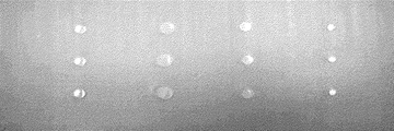
図2に接続用部分圧縮を施した陽極箔の写真を示す。図2は、接続用部分圧縮を施した後のエッチング箔の様子で、実施例1では、形状はだ円形であるが、任意の形状に加工することは可能である。圧延部は滑らかに平坦な形状で金属光沢を有しており、粗面化された部分が圧縮により埋まっていることが伺える。
Next, an oxide film as a dielectric is formed on the entire surface of the aluminum foil by chemical conversion treatment. The aluminum foil subjected to the etching treatment is immersed in boiling pure water to form pseudo boehmite on the surface. Next, an aluminum foil is immersed in an aqueous solution containing boric acid and carboxylic acid, and a voltage of 300 V is applied to perform anodization. Thereafter, heat treatment, depolarization treatment, and anodization are repeated, and then cleaning and drying are performed to complete the chemical conversion step.
Fig. 2 shows a photograph of the anode foil subjected to partial compression for connection. FIG. 2 shows the state of the etching foil after partial compression for connection. In Example 1, the shape is an oval, but it can be processed into an arbitrary shape. The rolled part has a smooth and flat shape and has a metallic luster, and it can be seen that the roughened part is filled by compression.
1…エッチング箔、2…アルミ箔、3…エッチングピット、4…プレスヘッド、5…圧縮部分、5a,5b…エッチングピットが閉じた部分。
DESCRIPTION OF
Claims (2)
An electrolytic capacitor etching foil having an etching pit, wherein a compression portion for connection for connecting the foils or other necessary members is provided.
Priority Applications (1)
| Application Number | Priority Date | Filing Date | Title |
|---|---|---|---|
| JP2006018909A JP2007201239A (en) | 2006-01-27 | 2006-01-27 | Etching foil for electrolytic capacitor and method for manufacturing positive electrode foil using it |
Applications Claiming Priority (1)
| Application Number | Priority Date | Filing Date | Title |
|---|---|---|---|
| JP2006018909A JP2007201239A (en) | 2006-01-27 | 2006-01-27 | Etching foil for electrolytic capacitor and method for manufacturing positive electrode foil using it |
Publications (1)
| Publication Number | Publication Date |
|---|---|
| JP2007201239A true JP2007201239A (en) | 2007-08-09 |
Family
ID=38455506
Family Applications (1)
| Application Number | Title | Priority Date | Filing Date |
|---|---|---|---|
| JP2006018909A Pending JP2007201239A (en) | 2006-01-27 | 2006-01-27 | Etching foil for electrolytic capacitor and method for manufacturing positive electrode foil using it |
Country Status (1)
| Country | Link |
|---|---|
| JP (1) | JP2007201239A (en) |
Cited By (4)
| Publication number | Priority date | Publication date | Assignee | Title |
|---|---|---|---|---|
| JP2011524629A (en) * | 2008-06-02 | 2011-09-01 | ハー.ツェー.スタルク ゲゼルシャフト ミット ベシュレンクテル ハフツング | Method for manufacturing an electrolytic capacitor with low leakage current |
| JP2011204729A (en) * | 2010-03-24 | 2011-10-13 | Hitachi Aic Inc | Anode for electrolytic capacitor, and method for manufacturing the same |
| JP2011204728A (en) * | 2010-03-24 | 2011-10-13 | Hitachi Aic Inc | Anode for electrolytic capacitor, and electrolytic capacitor |
| WO2017026295A1 (en) * | 2015-08-07 | 2017-02-16 | 株式会社村田製作所 | Capacitor |
-
2006
- 2006-01-27 JP JP2006018909A patent/JP2007201239A/en active Pending
Cited By (5)
| Publication number | Priority date | Publication date | Assignee | Title |
|---|---|---|---|---|
| JP2011524629A (en) * | 2008-06-02 | 2011-09-01 | ハー.ツェー.スタルク ゲゼルシャフト ミット ベシュレンクテル ハフツング | Method for manufacturing an electrolytic capacitor with low leakage current |
| JP2011204729A (en) * | 2010-03-24 | 2011-10-13 | Hitachi Aic Inc | Anode for electrolytic capacitor, and method for manufacturing the same |
| JP2011204728A (en) * | 2010-03-24 | 2011-10-13 | Hitachi Aic Inc | Anode for electrolytic capacitor, and electrolytic capacitor |
| WO2017026295A1 (en) * | 2015-08-07 | 2017-02-16 | 株式会社村田製作所 | Capacitor |
| JPWO2017026295A1 (en) * | 2015-08-07 | 2018-04-19 | 株式会社村田製作所 | Capacitor |
Similar Documents
| Publication | Publication Date | Title |
|---|---|---|
| US7180727B2 (en) | Capacitor with single sided partial etch and stake | |
| JP4660222B2 (en) | Solid electrolytic capacitor and manufacturing method thereof | |
| US20060076243A1 (en) | Electrode foil for electrolytic capacitor and method for manufacturing the same | |
| US8012222B2 (en) | Method and apparatus for interconnecting electrodes with partial titanium coating | |
| EP1028441A1 (en) | Solid electrolytic capacitor electrode foil, method of producing it and solid electrolytic capacitor | |
| TW201810320A (en) | Electrode foil, winding capacitor, electrode foil manufacturing method, and winding capacitor manufacturing method | |
| US7554791B2 (en) | Method and apparatus for electrically isolating capacitor electrodes using separator | |
| JP2007201239A (en) | Etching foil for electrolytic capacitor and method for manufacturing positive electrode foil using it | |
| JP2014072267A (en) | Aluminum collector foil having through hole and manufacturing method therefor | |
| JP3591463B2 (en) | Anode foil for multilayer electrolytic capacitor and multilayer electrolytic capacitor | |
| JP2009135343A (en) | Method of manufacturing aluminum electrode foil for electrolytic capacitor | |
| JP2010232451A (en) | Electrode for aluminum electrolytic capacitor | |
| JP2000068159A (en) | Solid electrolytic capacitor electrode foil therefor and its manufacture | |
| TW201903796A (en) | Electrode foil, wound capacitor, method of manufacturing electrode foil, and method of manufacturing wound capacitor | |
| JP2004253501A (en) | Solid electrolytic capacitor | |
| JP6762888B2 (en) | Manufacturing method of electrode holder and electrode for aluminum electrolytic capacitor | |
| JP3582451B2 (en) | Manufacturing method of anode foil for aluminum electrolytic capacitor | |
| JP6805881B2 (en) | Manufacturing method of solid electrolytic capacitor | |
| JP2008172185A (en) | Electrolytic capacitor | |
| WO2023127928A1 (en) | Electrolytic capacitor and production method for same | |
| JP3467827B2 (en) | Manufacturing method of anode foil for aluminum electrolytic capacitor | |
| EP1733403B1 (en) | Method for production of high capacitance electrolytic capacitor foil | |
| JP2009260017A (en) | Method of manufacturing solid electrolytic capacitor | |
| JP2010010350A (en) | Solid-state electrolytic capacitor and method of manufacturing the same | |
| TWI581285B (en) | Method of making capacitor element |