JP2007200375A - Optical recording medium and manufacturing method thereof - Google Patents
Optical recording medium and manufacturing method thereof Download PDFInfo
- Publication number
- JP2007200375A JP2007200375A JP2006014236A JP2006014236A JP2007200375A JP 2007200375 A JP2007200375 A JP 2007200375A JP 2006014236 A JP2006014236 A JP 2006014236A JP 2006014236 A JP2006014236 A JP 2006014236A JP 2007200375 A JP2007200375 A JP 2007200375A
- Authority
- JP
- Japan
- Prior art keywords
- recording
- recording layer
- dye
- wavelength
- light
- Prior art date
- Legal status (The legal status is an assumption and is not a legal conclusion. Google has not performed a legal analysis and makes no representation as to the accuracy of the status listed.)
- Pending
Links
Images

Classifications
-
- G—PHYSICS
- G11—INFORMATION STORAGE
- G11B—INFORMATION STORAGE BASED ON RELATIVE MOVEMENT BETWEEN RECORD CARRIER AND TRANSDUCER
- G11B7/00—Recording or reproducing by optical means, e.g. recording using a thermal beam of optical radiation by modifying optical properties or the physical structure, reproducing using an optical beam at lower power by sensing optical properties; Record carriers therefor
- G11B7/24—Record carriers characterised by shape, structure or physical properties, or by the selection of the material
- G11B7/2403—Layers; Shape, structure or physical properties thereof
- G11B7/24035—Recording layers
- G11B7/24044—Recording layers for storing optical interference patterns, e.g. holograms; for storing data in three dimensions [3D], e.g. volume storage
-
- G—PHYSICS
- G11—INFORMATION STORAGE
- G11B—INFORMATION STORAGE BASED ON RELATIVE MOVEMENT BETWEEN RECORD CARRIER AND TRANSDUCER
- G11B7/00—Recording or reproducing by optical means, e.g. recording using a thermal beam of optical radiation by modifying optical properties or the physical structure, reproducing using an optical beam at lower power by sensing optical properties; Record carriers therefor
- G11B7/24—Record carriers characterised by shape, structure or physical properties, or by the selection of the material
- G11B7/26—Apparatus or processes specially adapted for the manufacture of record carriers
-
- G—PHYSICS
- G11—INFORMATION STORAGE
- G11B—INFORMATION STORAGE BASED ON RELATIVE MOVEMENT BETWEEN RECORD CARRIER AND TRANSDUCER
- G11B7/00—Recording or reproducing by optical means, e.g. recording using a thermal beam of optical radiation by modifying optical properties or the physical structure, reproducing using an optical beam at lower power by sensing optical properties; Record carriers therefor
- G11B7/24—Record carriers characterised by shape, structure or physical properties, or by the selection of the material
- G11B7/2403—Layers; Shape, structure or physical properties thereof
- G11B7/24035—Recording layers
- G11B7/24038—Multiple laminated recording layers
Landscapes
- Engineering & Computer Science (AREA)
- Manufacturing & Machinery (AREA)
- Optical Record Carriers And Manufacture Thereof (AREA)
- Manufacturing Optical Record Carriers (AREA)
Abstract
【課題】記録層の厚み方向に広がる領域に複数のデータを記録することで三次元的に記録し記録層を厚くしても未記録媒体の透過像のビットエラーレートを低く抑える、すなわちノイズを低減することができる光記録媒体を提供する。
【解決手段】厚みが200μm以上であり、色素1、2を含み、データを三次元的に記録する記録層を有する光記録媒体において、色素1、2が吸収しない波長λaにおける記録する前の記録層の吸光度が0.030以下である。
【選択図】図1An object of the present invention is to record a plurality of data in an area extending in the thickness direction of a recording layer, to keep the bit error rate of a transmission image of an unrecorded medium low, that is, to reduce noise even if the recording layer is thickened by three-dimensional recording. An optical recording medium that can be reduced is provided.
In an optical recording medium having a thickness of 200 μm or more, including dyes 1 and 2 and having a recording layer for recording data three-dimensionally, recording before recording at a wavelength λa that is not absorbed by dyes 1 and 2 The absorbance of the layer is 0.030 or less.
[Selection] Figure 1
Description
本発明は、データを三次元的に記録する記録層を有する光記録媒体及びその製造方法に関する。 The present invention relates to an optical recording medium having a recording layer for recording data three-dimensionally and a method for manufacturing the same.
現在使用又は検討されている高容量光記録媒体としては、デジタルバーサタイルディスク(DVD:Digital Versatile Disc)、ブルーレイディスク(Blu−Ray Disk)、ハイディフィニションDVD(HD DVD:High Definition DVD)等が挙げられる。しかし、これらの媒体の容量としては、最高でも100GB程度と考えられており、これ以上の容量を有する高容量光記録媒体として、ホログラフィックメモリや多層光メモリに代表される、データを三次元的に記録する(体積記録を行う)光記録媒体が検討されている。 Examples of high-capacity optical recording media currently in use or under consideration include digital versatile discs (DVD), Blu-ray discs, and high definition DVDs (HD DVD). It is done. However, the capacity of these media is considered to be about 100 GB at the maximum, and as a high capacity optical recording medium having a capacity larger than this, data represented by holographic memory and multilayer optical memory is three-dimensionally stored. Optical recording media for recording (volume recording) have been studied.
ホログラフィックメモリや多層光メモリなどの体積記録をする光記録媒体は、記録層の面内方向だけでなく、記録層の三次元方向にわたり記録が行われることから、大容量化が可能である。ホログラフィックメモリでは、各種多重方法により、面内の同じ場所に何度も多重記録がなされる。多層光メモリでは、面内の同じ場所で多層の記録層それぞれに記録用のビットが形成される。 An optical recording medium that performs volume recording such as a holographic memory or a multi-layer optical memory can perform recording not only in the in-plane direction of the recording layer but also in the three-dimensional direction of the recording layer, so that the capacity can be increased. In the holographic memory, multiplex recording is performed many times at the same place in the surface by various multiplexing methods. In a multilayer optical memory, a recording bit is formed in each of the multilayer recording layers at the same place in the plane.
体積記録をする光記録媒体では、記録層が厚くなるに伴い入射した光が記録層を進む行程が長くなり、記録層の材料的なゆらぎなどにより、入射した光が散乱されることがある。ホログラフィックメモリにおいて、この散乱を低減することが課題となっているが(例えば、非特許文献1参照)、具体的にどの領域の散乱がどうS/Nやビットエラーレート(BER)に影響しているかは、まだよくわかっていない。
体積記録をする光記録媒体においては、未記録媒体の透過像のビットエラーレート低減、すなわちノイズの低減が重要である。未記録媒体の透過像のビットエラーレートと未記録媒体の散乱には相関があり、媒体の散乱の増加が未記録媒体の透過像のビットエラーレートを上昇させていることがわかった。 In an optical recording medium that performs volume recording, it is important to reduce the bit error rate of a transmission image of an unrecorded medium, that is, to reduce noise. It was found that there was a correlation between the bit error rate of the transmission image of the unrecorded medium and the scattering of the unrecorded medium, and the increase in the scattering of the medium increased the bit error rate of the transmission image of the unrecorded medium.
そこで、本発明は、三次元的に記録し記録層を厚くしてもビットエラーレートを低く抑えることができる光記録媒体を提供することを課題とする。 Therefore, an object of the present invention is to provide an optical recording medium that can keep the bit error rate low even if recording is performed three-dimensionally and the recording layer is thickened.
また、本発明は、三次元的に記録し記録層を厚くしてもビットエラーレートを低く抑えることができる光記録媒体の製造方法を提供することを課題とする。 Another object of the present invention is to provide a method for manufacturing an optical recording medium that can keep the bit error rate low even if recording is performed three-dimensionally and the recording layer is thickened.
前記課題を解決するため、本発明の光記録媒体は、厚みが200μm以上であり少なくとも1種類の色素を含み、データを三次元的に記録する記録層を有する光記録媒体において、前記色素が吸収をもたない長波長側の可視光の波長における記録する前の記録層の吸光度が0.030以下にすることを特徴とする。色素が光を吸収しない波長で吸光度を測定しているので、この波長で測定される吸光度は、光の吸収によるものではなく、光の散乱によるものである。さらに、この吸光度が未記録媒体の透過像のビットエラーレートと相関関係を有する、吸光度が0.030以下になることではじめて目的とする低ビットエラーレートを実現する光記録媒体を得ることができる。 In order to solve the above-mentioned problems, the optical recording medium of the present invention has an optical recording medium having a thickness of 200 μm or more, containing at least one kind of dye, and having a recording layer for recording data three-dimensionally. The absorbance of the recording layer before recording at the wavelength of visible light on the long-wavelength side having no light is 0.030 or less. Since the absorbance is measured at a wavelength at which the dye does not absorb light, the absorbance measured at this wavelength is not due to light absorption but due to light scattering. Furthermore, an optical recording medium that achieves a target low bit error rate can be obtained only when the absorbance has a correlation with the bit error rate of a transmission image of an unrecorded medium and the absorbance is 0.030 or less. .
また、本発明の光記録媒体の製造方法としては、データを三次元的に記録する記録層を構成する素材を溶解した溶液を生成し、この溶液をろ過し、ろ過された前記溶液を乾燥させて粉砕し、固化させて厚みが200μm以上の記録層を形成することを特徴とする。 In addition, as a method for producing an optical recording medium of the present invention, a solution in which a material constituting a recording layer for recording data three-dimensionally is generated, a solution is filtered, and the filtered solution is dried. And then pulverizing and solidifying to form a recording layer having a thickness of 200 μm or more.
本発明によれば、三次元的に記録し記録層を厚くしても未記録媒体の透過像のビットエラーレートを低く抑えることができる光記録媒体を提供できる。 According to the present invention, it is possible to provide an optical recording medium capable of suppressing the bit error rate of a transmission image of an unrecorded medium to a low level even if recording is performed three-dimensionally and the recording layer is thickened.
また、本発明によれば、三次元的に記録し記録層を厚くしても未記録媒体の透過像のビットエラーレートを低く抑えることができる光記録媒体の製造方法を提供できる。 Furthermore, according to the present invention, it is possible to provide a method for manufacturing an optical recording medium that can suppress the bit error rate of a transmission image of an unrecorded medium to a low level even if recording is performed three-dimensionally and the recording layer is thickened.
次に、本発明の実施の形態について適宜図面を参照しながら詳細に説明する。実施の形態においては、記録層の厚み方向に体積記録をする光記録媒体について説明し、具体的には、ホログラフィ(干渉)を用いて光情報を記録するホログラフィックメモリについて説明する。なお、本発明は、多層光メモリにも適用することができる。 Next, embodiments of the present invention will be described in detail with reference to the drawings as appropriate. In the embodiment, an optical recording medium that performs volume recording in the thickness direction of the recording layer will be described. Specifically, a holographic memory that records optical information using holography (interference) will be described. The present invention can also be applied to multilayer optical memories.
本発明の実施の形態に係るホログラフィックメモリは、記録層を有している。また、必要に応じて、記録層の上下に光透過性基板を設けてもよい。 The holographic memory according to the embodiment of the present invention has a recording layer. Further, if necessary, a light transmissive substrate may be provided above and below the recording layer.
記録層には、周知のとおり、参照光と記録光とが記録層に照射されることによってデータである光情報が干渉縞として記録される。また同じ場所に異なる干渉縞を多数形成(多重記録)することにより、高容量化できる。多重方式としては、シフト多重方式や、角度多重方式、波長多重方式、位相コード多重方式、ポリトピック(Polytopic)多重方式、これらの組み合わせによる多重方式を用いることができる。例えば、角度多重方式であれば、多重記録しようとする各光情報の記録光ごとに、参照光の入射角度が変更される。具体的には、記録光および所定の入射角度に設定された参照光が記録層の記録箇所に照射されることによって記録層に干渉縞が形成される。 As is well known, optical information as data is recorded on the recording layer as interference fringes by irradiating the recording layer with reference light and recording light. Further, by forming many different interference fringes at the same place (multiple recording), the capacity can be increased. As the multiplexing method, a shift multiplexing method, an angle multiplexing method, a wavelength multiplexing method, a phase code multiplexing method, a polytopic multiplexing method, or a multiplexing method based on a combination thereof can be used. For example, in the case of angle multiplexing, the incident angle of the reference light is changed for each recording light of each optical information to be multiplexed recorded. Specifically, interference fringes are formed in the recording layer by irradiating the recording portion of the recording layer with the recording light and the reference light set at a predetermined incident angle.
記録層に干渉縞が記録されると、記録層内において、干渉縞の明暗に沿って記録層の素材が変化したり、物質の移動が起こったりして、屈折率差や透過率差が生じることにより記録がなされる。現在、検討されている記録層の素材としては、フォトポリマ材料、屈折率変調用色素型材料、ハロゲン化銀、重クロム酸ゼラチン、フォトリフラクティブ材料、フォトクロミック材料などが挙げられる。 When interference fringes are recorded on the recording layer, the material of the recording layer changes or the substance moves along the brightness and darkness of the interference fringes in the recording layer, resulting in a difference in refractive index and transmittance. A record is made. Examples of recording layer materials that are currently under consideration include photopolymer materials, refractive index modulation dye-type materials, silver halides, dichromated gelatin, photorefractive materials, and photochromic materials.
フォトポリマ材料は、高回折効率が得られること、低ノイズであること、記録後に完全に定着すれば保存安定性が良好であることから、注目を集めており素材開発が進められている。典型的なフォトポリマ材料は、バインダ、重合性モノマ、増感色素、重合開始剤などを含有している。 Photopolymer materials are attracting attention and are being developed because of their high diffraction efficiency, low noise, and good storage stability if they are completely fixed after recording. A typical photopolymer material contains a binder, a polymerizable monomer, a sensitizing dye, a polymerization initiator, and the like.
バインダとモノマは屈折率の異なるものを使用する。記録時には記録層内に干渉縞の明部と暗部が形成される。干渉縞の明部においては、増感色素が励起し電子を放出し、放出された電子が重合開始剤に移動し、重合開始剤がラジカルもしくは酸を発生し、ラジカルもしくは酸がモノマに移動し、モノマの重合反応が行われる。この結果、干渉縞の明部では、隣接する暗部からも重合するモノマが集められ、モノマがリッチになり、干渉縞の暗部では、モノマが抜けるのに対応して、バインダがリッチになる。これらのモノマリッチとバインダリッチ部分の屈折率差で、干渉縞を記録している。 Binders and monomers having different refractive indexes are used. During recording, bright and dark portions of interference fringes are formed in the recording layer. In the bright part of the interference fringes, the sensitizing dye is excited to emit electrons, the emitted electrons move to the polymerization initiator, the polymerization initiator generates radicals or acids, and the radicals or acids move to the monomers. The monomer polymerization reaction is carried out. As a result, in the bright part of the interference fringe, monomers that are superposed from the adjacent dark part are collected, and the monomer becomes rich, and in the dark part of the interference fringe, the binder becomes rich corresponding to the loss of the monomer. Interference fringes are recorded by the difference in refractive index between these mono-rich and binder-rich portions.
次に、例えば角度多重方式であれば、参照光の入射角度が変更されるとともに、この参照光が他の光情報を持つ記録光と干渉し、記録された記録箇所と同じ箇所に干渉縞が形成されることによって他の光情報が重ねて記録される。以下、同様に多重記録することにより記録層の1つの記録箇所に複数の光情報が記録されていく。 Next, for example, in the case of the angle multiplexing method, the incident angle of the reference light is changed, the reference light interferes with recording light having other optical information, and interference fringes are formed at the same location as the recorded recording location. By being formed, other optical information is recorded in an overlapping manner. Thereafter, a plurality of optical information is recorded in one recording location of the recording layer by performing multiple recording in the same manner.
そして、1つの記録箇所への所定の光情報の多重記録が終了すると、記録層の他の記録箇所へ移動する。他の記録箇所と前述の記録箇所とは、一部が重なっていても、重なっていなくても良い。位置決めされた記録光および参照光は、複数の光情報を他の記録箇所に多重記録していく。 Then, when the multiplex recording of the predetermined optical information in one recording location is completed, the recording layer moves to another recording location. Other recording locations and the aforementioned recording locations may or may not partially overlap. The positioned recording light and reference light multiplex-record a plurality of optical information at other recording locations.
そして、記録層に対する所定の光情報の記録が終了すると、光情報の記録に使用されなかった重合性モノマは、レーザや白色光源で全面露光されて定着され、あるいは熱処理で定着される。 When the recording of the predetermined optical information on the recording layer is completed, the polymerizable monomer that has not been used for recording the optical information is fixed by being exposed to the whole surface with a laser or a white light source, or by heat treatment.
記録層に記録された光情報としてのホログラムは、周知のとおり、再生光が各記録箇所に照射されることによって生成する回折光として読み出される。例えば角度多重した媒体においては、各記録箇所に多重記録された複数の光情報のそれぞれは、各光情報が記録されたときの参照光の入射角度に設定された再生光が照射されることによって読み出される。 As is well known, the hologram as optical information recorded on the recording layer is read as diffracted light generated by irradiating each recording location with reproduction light. For example, in an angle-multiplexed medium, each of a plurality of optical information multiplexed and recorded at each recording location is irradiated with reproduction light set at the incident angle of the reference light when each optical information is recorded. Read out.
記録層は、光が照射されることによって光情報が記録される層であって、厚みが200μm以上、好ましくは0.2〜2.5mm、より好ましくは0.5〜2.5mmである。厚みを200μm以上にすることにより、ホログラフィックメモリの製品化の際に要求される多重記録の回数を満足することができる。また、2.5mm以下にすることにより、材料を削減でき、製品化の際にコストを削減することができる。 The recording layer is a layer on which optical information is recorded by being irradiated with light, and has a thickness of 200 μm or more, preferably 0.2 to 2.5 mm, more preferably 0.5 to 2.5 mm. By setting the thickness to 200 μm or more, it is possible to satisfy the number of multiplex recordings required when a holographic memory is commercialized. Moreover, by making it 2.5 mm or less, material can be reduced and cost can be reduced in the case of commercialization.
重合性モノマとしては、重合性基があれば特に限定はなく、例えば、ラジカル重合性モノマ、カチオン重合性モノマ、これらのモノマを併用したものが挙げられ、具体的には、エポキシ基、エチレン性不飽和基等の重合性基を含む化合物が挙げられる。重合性モノマは、これらの重合性基を分子内に1つ以上含んでいればよく、分子内に2つ以上の重合性基を含む重合性モノマは、それらの重合性基が異なるものでもよいし、同じものでもよい。 The polymerizable monomer is not particularly limited as long as it has a polymerizable group, and examples thereof include radically polymerizable monomers, cationically polymerizable monomers, and combinations of these monomers, specifically, epoxy groups, ethylenic monomers. Examples thereof include compounds containing a polymerizable group such as an unsaturated group. The polymerizable monomer only needs to contain one or more of these polymerizable groups in the molecule, and the polymerizable monomer containing two or more polymerizable groups in the molecule may have different polymerizable groups. And the same thing may be used.
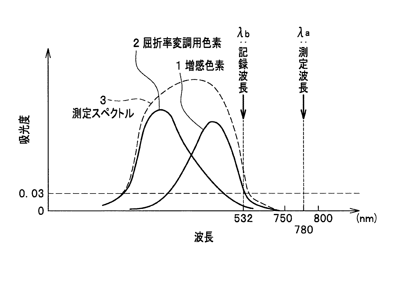
図1に示すように、増感色素1としては、記録光(参照光)の記録波長λbに吸収を有するものであれば特に制限はない。しかし反応は増感色素の密度(すなわち反応物質間の距離)に比例するため、記録波長λbにおける増感色素1の光吸収係数εが低いものを使用し、増感色素添加量を増感させることが好ましい。記録層の吸光度の測定を測定波長λaで行う。測定波長λaは、増感色素1が吸収しない長波長側の可視光の波長に設定する。そして、測定波長λaにおける記録する前の記録層の吸光度は、0.030以下とする。なお、この吸光度の値は、記録層の膜厚で補正していない。記録層に対して入射光の光量に対する透過光の光量の比に基づいている。したがって、記録層の膜厚が200μm以上であっても吸光度は0.030以下になっている。また、記録波長λbが532〜633nmであれば、測定波長λaは増感色素が吸収しない長波長側の可視光の波長750〜800nm、例えば780nmに設定すればよい。また、次世代に進み、記録波長λbが400〜450nmのような短波長側にシフトし増感色素の吸収スペクトルも短波長側にシフトすれば、測定波長λaも短波長側にシフトさせ、増感色素が吸収しない長波長側の可視光の波長500〜800nm、例えば650、780nmに設定すればよい。 As shown in FIG. 1, the sensitizing dye 1 is not particularly limited as long as it has absorption at the recording wavelength λb of the recording light (reference light). However, since the reaction is proportional to the density of the sensitizing dye (that is, the distance between the reactants), the sensitizing dye 1 having a low light absorption coefficient ε at the recording wavelength λb is used to sensitize the added amount of the sensitizing dye. It is preferable. The absorbance of the recording layer is measured at the measurement wavelength λa. The measurement wavelength λa is set to the wavelength of visible light on the long wavelength side that the sensitizing dye 1 does not absorb. The absorbance of the recording layer before recording at the measurement wavelength λa is 0.030 or less. This absorbance value is not corrected by the film thickness of the recording layer. This is based on the ratio of the amount of transmitted light to the amount of incident light with respect to the recording layer. Therefore, the absorbance is 0.030 or less even when the film thickness of the recording layer is 200 μm or more. If the recording wavelength λb is 532 to 633 nm, the measurement wavelength λa may be set to a wavelength of 750 to 800 nm of visible light on the long wavelength side that is not absorbed by the sensitizing dye, for example, 780 nm. If the recording wavelength λb is shifted to the short wavelength side such as 400 to 450 nm and the absorption spectrum of the sensitizing dye is also shifted to the short wavelength side, the measurement wavelength λa is also shifted to the short wavelength side and increased. What is necessary is just to set to the wavelength of 500-800 nm of visible light of the long wavelength side which a dye does not absorb, for example, 650, 780 nm.
増感色素の具体例としては、シアニン系、メロシアニン系、フタロシアニン系、アゾ系、アゾメチン系、インドアニリン系、キサンテン系、クマリン系、ポリメチン系、ジアリルエテン系、フルギドフルオラン系、アントラキノン系、スチリル系等の公知の有機色素が挙げられる。また、これら以外にも増感色素としては、錯体色素が用いられても良い。 Specific examples of the sensitizing dye include cyanine, merocyanine, phthalocyanine, azo, azomethine, indoaniline, xanthene, coumarin, polymethine, diallylethene, fulgidofluorane, anthraquinone, styryl. Known organic dyes such as those of the system are mentioned. In addition to these, a complex dye may be used as the sensitizing dye.
重合開始剤としては、ラジカル発生剤、酸発生剤等が挙げられる。 Examples of the polymerization initiator include a radical generator and an acid generator.
バインダとしては、例えば、塩素化ポリエチレン、ポリメチルメタクリレート、メチルメタクリレートと他の(メタ)アクリル酸アルキルエステルの共重合体、塩化ビニルとアクリロニトリルの共重合体、ポリ酢酸ビニル、ポリビニルアルコール、ポリビニルホルマール、ポリビニルブチラール、ポリビニルピロリドン、エチルセルロース、アセチルセルロース、ポリカーボネート等が挙げられる。なお、バインダの屈折率は、重合性モノマの重合物(ポリマ)の屈折率との差が大きなものが好ましい。ただし、屈折率の差が大きすぎるような組み合わせでは、バインダと重合性モノマとの相溶性が低下し、その結果として光の散乱が大きくなる場合があるため、適当な屈折率のバインダが求められる。 Examples of the binder include chlorinated polyethylene, polymethyl methacrylate, copolymers of methyl methacrylate and other (meth) acrylic acid alkyl esters, copolymers of vinyl chloride and acrylonitrile, polyvinyl acetate, polyvinyl alcohol, polyvinyl formal, Examples thereof include polyvinyl butyral, polyvinyl pyrrolidone, ethyl cellulose, acetyl cellulose, and polycarbonate. The refractive index of the binder preferably has a large difference from the refractive index of the polymerized polymer (polymer). However, in a combination in which the difference in refractive index is too large, the compatibility between the binder and the polymerizable monomer is lowered, and as a result, light scattering may increase, so a binder with an appropriate refractive index is required. .
また、記録層は、必要に応じて、増感剤、光学的増白剤、紫外線吸収剤、熱安定剤、連鎖移動剤、可塑剤、着色剤等のこの種の光記録媒体の記録層の形成に常用されるものを含んでいてもよい。 In addition, the recording layer may be a recording layer of this type of optical recording medium such as a sensitizer, an optical brightener, an ultraviolet absorber, a heat stabilizer, a chain transfer agent, a plasticizer, and a colorant. What is commonly used for formation may be included.
現在、検討されている記録層の素材の、フォトポリマ材料以外の素材としては、屈折率変調用色素型材料が挙げられる。屈折率変調用色素型材料は、干渉縞の明部において、屈折率変調用色素の発色反応または消色反応を起こし、干渉縞の暗部に対して、屈折率差や透過率差などの物性値の差を生じさせる。屈折率変調用色素型材料は、バインダ、増感色素、屈折率変調用色素と酸発生剤を有している。フォトポリマと同様に、干渉縞が生成されると、干渉縞の明部において、増感色素が励起し、電子が放出される。放出された電子は酸発生剤に移動し、酸発生剤より酸が発生する。この酸により屈折率変調用色素が消色反応により消色し、屈折率が変化する。あるいは、屈折率変調用色素が発色反応により発色し、屈折率が変化する。発色反応の場合は、屈折率変調用色素を特に色素前駆体と呼ぶ場合がある。また酸発生以外の機構で、発色や消色反応を起こさせてもよい。 As a material other than the photopolymer material of the recording layer material currently being studied, there is a dye-type material for refractive index modulation. The dye-type material for refractive index modulation causes a coloring reaction or a decoloring reaction of the refractive index modulation dye in the bright part of the interference fringe, and a physical property value such as a refractive index difference or a transmittance difference with respect to the dark part of the interference fringe. Cause the difference. The refractive index modulating dye-type material has a binder, a sensitizing dye, a refractive index modulating dye, and an acid generator. Similar to the photopolymer, when the interference fringes are generated, the sensitizing dye is excited and electrons are emitted in the bright part of the interference fringes. The emitted electrons move to the acid generator, and acid is generated from the acid generator. With this acid, the refractive index modulating dye is decolored by a decoloring reaction, and the refractive index changes. Alternatively, the refractive index modulating dye is colored by a color development reaction, and the refractive index changes. In the case of a color development reaction, the refractive index modulation dye may be particularly referred to as a dye precursor. In addition, coloring or decoloring reaction may be caused by a mechanism other than acid generation.
図1に示すように、記録層は、増感色素1と屈折率変調用色素2を含んでいる。増感色素1としては、記録光(参照光)の記録波長λbに吸収を有するものであれば特に制限はない。しかし反応は増感色素の密度に比例するため、記録波長λbにおける増感色素1の光吸収係数εが低いものを使用し、増感色素添加量を増感させることが好ましい。増感色素1には、フォトポリマ材料に含まれる増感色素1と同じものを用いることができる。 As shown in FIG. 1, the recording layer includes a sensitizing dye 1 and a refractive index modulating dye 2. The sensitizing dye 1 is not particularly limited as long as it has absorption at the recording wavelength λb of the recording light (reference light). However, since the reaction is proportional to the density of the sensitizing dye, it is preferable to use a sensitizing dye 1 having a low light absorption coefficient ε at the recording wavelength λb to sensitize the addition amount of the sensitizing dye. As the sensitizing dye 1, the same sensitizing dye 1 contained in the photopolymer material can be used.
図1に示すように、増感色素1としては、記録光(参照光)の記録波長λbに吸収を有するものであれば特に制限はない。しかし反応は増感色素の密度に比例するため、記録波長λbにおける増感色素1の光吸収係数εが低いものを使用し、増感色素添加量を増感させることが好ましい。記録層の吸光度の測定を測定波長λaで行う。測定波長λaは、増感色素1が吸収しない長波長側の可視光の波長に設定する。そして、測定波長λaにおける記録する前の記録層の吸光度は、0.030以下とする。なお、この吸光度の値は、記録層の膜厚で補正していない。記録層に対して入射光の光量に対する透過光の光量の比に基づいている。したがって、記録層の膜厚が200μm以上であっても吸光度は0.030以下になっている。また、記録波長λbが532〜633nmであれば、測定波長λaは増感色素が吸収しない長波長側の可視光の波長750〜800nm、例えば780nmに設定すればよい。また、次世代に進み、記録波長λbが400〜450nmのような短波長側にシフトし増感色素の吸収スペクトルも短波長側にシフトすれば、測定波長λaも短波長側にシフトさせ、増感色素が吸収しない長波長側の可視光の波長500〜800nm、例えば650、780nmに設定すればよい。 As shown in FIG. 1, the sensitizing dye 1 is not particularly limited as long as it has absorption at the recording wavelength λb of the recording light (reference light). However, since the reaction is proportional to the density of the sensitizing dye, it is preferable to use a sensitizing dye 1 having a low light absorption coefficient ε at the recording wavelength λb to sensitize the addition amount of the sensitizing dye. The absorbance of the recording layer is measured at the measurement wavelength λa. The measurement wavelength λa is set to the wavelength of visible light on the long wavelength side that the sensitizing dye 1 does not absorb. The absorbance of the recording layer before recording at the measurement wavelength λa is 0.030 or less. This absorbance value is not corrected by the film thickness of the recording layer. This is based on the ratio of the amount of transmitted light to the amount of incident light with respect to the recording layer. Therefore, the absorbance is 0.030 or less even when the film thickness of the recording layer is 200 μm or more. If the recording wavelength λb is 532 to 633 nm, the measurement wavelength λa may be set to a wavelength of 750 to 800 nm of visible light on the long wavelength side that is not absorbed by the sensitizing dye, for example, 780 nm. If the recording wavelength λb is shifted to the short wavelength side such as 400 to 450 nm and the absorption spectrum of the sensitizing dye is also shifted to the short wavelength side, the measurement wavelength λa is also shifted to the short wavelength side and increased. What is necessary is just to set to the wavelength of 500-800 nm of visible light of the long wavelength side which a dye does not absorb, for example, 650, 780 nm.
また、現在、検討されている記録層の素材としては、ハロゲン化銀、重クロム酸ゼラチン、フォトリフラクティブ材料、フォトクロミック材料などが挙げられる。 In addition, examples of the material of the recording layer currently under consideration include silver halide, dichromated gelatin, photorefractive material, and photochromic material.
ハロゲン化銀は、感度が高く、比較的解像度も高いが、湿式処理が必要でかつ煩雑であり、また、散乱が大きく、耐光性が劣るという問題を有する。そのため、メモリ用途としては、改善する余地が大きい。 Although silver halide has high sensitivity and relatively high resolution, it has a problem that it requires wet processing and is complicated, has a large scattering, and is inferior in light resistance. Therefore, there is much room for improvement as a memory application.
重クロム酸ゼラチンは、回折効率が高く、低ノイズという特色を有するが、感度が低く、また、記録保存性が良好でないため、メモリ用途としては、改善する余地がある。 Bichromated gelatin has the characteristics of high diffraction efficiency and low noise, but has low sensitivity and poor recording storage stability, so there is room for improvement in memory applications.
フォトリフラクティブ材料は、書き換え可能という特色を有するが、記録時に高電圧印加が必要で、記録保持性が良好でないため、メモリ用途としては、改善する余地がある。 Photorefractive materials have the feature of being rewritable, but they require a high voltage application during recording and have poor record retention, so there is room for improvement in memory applications.
フォトクロミック材料も、書き換え可能という特色を有するが、感度が極めて低く、記録保持性も良好でないため、メモリ用途としては、改善する余地がある。 Photochromic materials also have the feature of being rewritable, but they have room for improvement as memory applications because of their extremely low sensitivity and poor record retention.
そこで、ハロゲン化銀、重クロム酸ゼラチン、フォトリフラクティブ材料、フォトクロミック材料、フォトポリマ材料や屈折率変調用色素型材料など記録層の材料を組み合わせてもよい。例えば、発色反応あるいは消色反応を起こす屈折率変調用色素型材料と重合反応を起こすフォトポリマ材料を組み合わせることにより、屈折率変調用色素型材料に対しても定着を行うことが可能になり、容易に屈折率差を獲得できるので、記録層の素材としての適性を相乗的に獲得することができる。また、フォトリフラクティブ材料とフォトポリマ材料を組み合わせても、同様に、フォトリフラクティブ材料に対しても定着を行うことが可能になり、容易に屈折率差を獲得できるので、記録層の素材としての適性を相乗的に獲得することができる。なお、記録層は、記録方式に応じて熱重合性樹脂組成物(熱硬化性樹脂組成物)で形成されたものであってもよい。 Therefore, recording layer materials such as silver halide, dichromated gelatin, photorefractive material, photochromic material, photopolymer material, and refractive index modulation dye-type material may be combined. For example, by combining a refractive index-modulating dye-type material that causes a coloring reaction or a decoloring reaction and a photopolymer material that causes a polymerization reaction, it becomes possible to fix the refractive index-modulating dye-type material, Since the refractive index difference can be easily obtained, the suitability of the recording layer as a material can be obtained synergistically. In addition, even when a photorefractive material and a photopolymer material are combined, it is possible to fix to a photorefractive material as well, and a refractive index difference can be easily obtained. Can be obtained synergistically. The recording layer may be formed of a thermopolymerizable resin composition (thermosetting resin composition) according to the recording method.
また、光記録媒体は、記録層を保持し保護するために、記録層の上下に光透過性基板を備えていてもよい。光透過性基板の厚みは、0.05〜1.2mm程度であればよい。光透過性基板の材料としては、例えば、ガラス等の無機物や、ポリカーボネート、トリアセチルセルロース、シクロオレフィンポリマー、ポリエチレンテレフタレート、ポリフェニレンスルフィド、アクリル樹脂、メタクリル樹脂、ポリスチレン樹脂、塩化ビニル樹脂、エポキシ樹脂、ポリエステル樹脂、アモルファスポリオレフィン等の樹脂が挙げられる。中でも、ガラス、ポリカーボネート、およびトリアセチルセルロースは、複屈折が小さいので好ましい。なお、光透過性基板は、同一の材料で形成されていても、あるいは異なる材料で形成されていてもよい。また、光透過性基板の表面には、反射防止コーティングや、酸素透過防止コーティング、水分透過防止コーティング、UVカットコーティング等が必要に応じて施されていてもよい。 Further, the optical recording medium may include a light transmissive substrate above and below the recording layer in order to hold and protect the recording layer. The thickness of the light transmissive substrate may be about 0.05 to 1.2 mm. Examples of the material for the light-transmitting substrate include inorganic substances such as glass, polycarbonate, triacetyl cellulose, cycloolefin polymer, polyethylene terephthalate, polyphenylene sulfide, acrylic resin, methacrylic resin, polystyrene resin, vinyl chloride resin, epoxy resin, and polyester. Examples of the resin include resins and amorphous polyolefins. Of these, glass, polycarbonate, and triacetyl cellulose are preferable because of their low birefringence. Note that the light-transmitting substrate may be formed of the same material or different materials. The surface of the light transmissive substrate may be provided with an antireflection coating, an oxygen permeation prevention coating, a moisture permeation prevention coating, a UV cut coating, or the like as necessary.
本発明の実施の形態に係るホログラフィックメモリは、素材を溶解した溶液を生成する工程と、次にこの溶液をろ過する工程と、ろ過された前記溶液を乾燥させて固形物を生成する工程と、この固形物を粉砕したフレークを生成する工程と、このフレークを成型して厚みが200μm以上の記録層を形成する工程とを含む製造方法によって得ることができる。フレークを成型する方法としては、温度、圧力もしくは両方をかけてプレスを行ったり、材料をガラス状もしくは液体状に溶融して型に流しいれたりする成型方法が挙げられる。 A holographic memory according to an embodiment of the present invention includes a step of generating a solution in which a material is dissolved, a step of filtering the solution, and a step of drying the filtered solution to generate a solid matter. The production method includes a step of producing flakes obtained by pulverizing the solid, and a step of forming the recording layer having a thickness of 200 μm or more by molding the flakes. Examples of the method for molding flakes include a molding method in which pressing is performed by applying temperature, pressure, or both, and a material is melted into a glass or liquid and then poured into a mold.
ろ過に関しては、フィルタの径を変えることにより、散乱度合いを変えることができる。また、ろ過だけでなく、分散を強化(分散時間の増加、回転数の増加、分散メディアの充填率増加等)することによっても、散乱を低減できる。一方媒体においても、散乱防止剤として界面活性剤を添加したり、バインダや色素に相溶性を向上させるような基を導入したりすることにより、不揮発性オイルを添加したりすることにより、散乱を低減できる。これらの手法は、単独でもちいてもよいが、複数組み合わせて使用することで、より大きな効果が期待できる。 Regarding filtration, the degree of scattering can be changed by changing the filter diameter. In addition to filtration, scattering can also be reduced by enhancing dispersion (increase in dispersion time, increase in rotational speed, increase in filling rate of dispersion media, etc.). On the other hand, in the medium, scattering can be achieved by adding a non-volatile oil by adding a surfactant as an anti-scattering agent or by introducing a group that improves compatibility with a binder or a dye. Can be reduced. These methods may be used singly, but a greater effect can be expected by using a plurality of these methods in combination.
実施の形態に係るホログラフィックメモリによれば、未記録媒体の透過像のビットエラーレートを低下させることができる。具体的には、ビットエラーレートを10−2未満にすることができる。未記録媒体の透過像のビットエラーレートを低減させることで、ノイズの低い媒体を実現できる。しかし、ホログラフィックメモリにおいて、未記録媒体の透過像のビットエラーレートと相関する散乱の評価方法は提案されていなかった。 According to the holographic memory according to the embodiment, the bit error rate of a transmission image of an unrecorded medium can be reduced. Specifically, the bit error rate can be less than 10 −2 . By reducing the bit error rate of the transmission image of the unrecorded medium, a medium with low noise can be realized. However, in the holographic memory, a method for evaluating scattering that correlates with the bit error rate of a transmission image of an unrecorded medium has not been proposed.
そこで、未記録媒体の透過像のビットエラーレートと相関する散乱の評価方法を確立した。散乱として、ビットエラーレートに影響を及ぼしている光の波長は、記録波長λbと同程度の大きさの波長であると考えられる。そこで、直接的には、記録波長λbの光を記録層に照射し、散乱する光を計測すればよいが、記録波長λbの光は増感色素1と屈折率変調用色素2によって吸収されてしまうので、散乱する光を正確に評価することができない。実施の形態では、増感色素1と屈折率変調用色素2によって吸収されない波長を測定波長λaとして選択している。測定波長λaの光を記録層に入射すると、色素による吸収がないので、反射光と透過光を入射光から引いた分が散乱光であると考えられる。これらのことからλaにおける吸光度が大きいほど散乱が多くなるという相関関係があると考えられる。このように、測定波長λaの吸光度を測定することにより、散乱の大きさを定量的に評価することができる。 Therefore, a method for evaluating scattering that correlates with the bit error rate of a transmission image of an unrecorded medium was established. It is considered that the wavelength of light that has an influence on the bit error rate as scattering is the same as the wavelength of the recording wavelength λb. Therefore, it is sufficient to directly irradiate the recording layer with light of the recording wavelength λb and measure the scattered light, but the light of the recording wavelength λb is absorbed by the sensitizing dye 1 and the refractive index modulation dye 2. Therefore, the scattered light cannot be accurately evaluated. In the embodiment, the wavelength that is not absorbed by the sensitizing dye 1 and the refractive index modulation dye 2 is selected as the measurement wavelength λa. When light having the measurement wavelength λa is incident on the recording layer, since there is no absorption by the dye, the amount of reflected light and transmitted light subtracted from the incident light is considered to be scattered light. From these facts, it is considered that there is a correlation that the greater the absorbance at λa, the greater the scattering. Thus, the magnitude of scattering can be quantitatively evaluated by measuring the absorbance at the measurement wavelength λa.
次に、この散乱の評価方法を用いて、散乱の大きさと相関関係がある測定波長λaの吸光度と、未記録媒体の透過像のビットエラーレートとの関係を明らかにしている。複数のサンプルについて、吸光度と未記録媒体の透過像のビットエラーレートを測定することにより、測定波長λaの吸光度を0.030以下に設定すれば、未記録媒体の透過像のビットエラーレートを10−2以下にすることができることがわかった。 Next, this scattering evaluation method is used to clarify the relationship between the absorbance at the measurement wavelength λa, which has a correlation with the magnitude of scattering, and the bit error rate of the transmission image of the unrecorded medium. By measuring the absorbance and the bit error rate of the transmission image of the unrecorded medium for a plurality of samples, and setting the absorbance at the measurement wavelength λa to 0.030 or less, the bit error rate of the transmission image of the unrecorded medium is set to 10 -2 or less.
実施の形態によれば、記録層を厚くしても未記録媒体の透過像のビットエラーレートを低くできるホログラフィックメモリを提供できる。そして、複数のサンプルについて、吸光度と未記録媒体の透過像のビットエラーレートを測定する過程で、未記録媒体の透過像のビットエラーレートを0.030以下に下げる記録層の製造方法を確立している。また、実施の形態では、ホログラフィ(干渉)を用いて光情報を記録する光記録媒体について説明したが、本発明はこれに限定されるものではなく、多層光メモリであってもよい。 According to the embodiment, it is possible to provide a holographic memory that can reduce the bit error rate of a transmission image of an unrecorded medium even if the recording layer is thickened. Then, for a plurality of samples, in the process of measuring the absorbance and the bit error rate of the transmission image of the unrecorded medium, a manufacturing method for the recording layer is established that reduces the bit error rate of the transmission image of the unrecorded medium to 0.030 or less. ing. In the embodiments, the optical recording medium for recording optical information using holography (interference) has been described. However, the present invention is not limited to this and may be a multilayer optical memory.
次に、本発明の光記録媒体を実施例に基づいてさらに具体的に説明するが、本発明はこれらの実施例に限定されるものではない。 Next, the optical recording medium of the present invention will be described in more detail based on examples, but the present invention is not limited to these examples.
<光記録媒体の製造>
実施例では、屈折率変調用色素型材料を用いて光記録媒体を製造した。まず、溶液の調製を行った。記録層を作製するために、表1に示すバインダ、酸で消色する色素、酸発生剤、増感色素、ならびに溶剤としての塩化メチレンおよびアセトニトリルの各素材を表1に示す質量比となるように秤量した。秤量は赤色灯下で行った。なお、各素材間の相溶性を向上させ、よく分散させるために、散乱防止剤を添加してもよい。散乱防止剤としては、端末にOH基とアルキル基を持つ界面活性剤であればよい。
<Manufacture of optical recording media>
In Examples, an optical recording medium was manufactured using a refractive index modulation dye-type material. First, a solution was prepared. In order to produce the recording layer, the binder, the dye that is decolored with acid, the acid generator, the sensitizing dye, and each material of methylene chloride and acetonitrile as the solvent have the mass ratio shown in Table 1. Weighed out. Weighing was performed under a red light. In addition, in order to improve the compatibility between each raw material and to disperse | distribute well, you may add an antiscattering agent. The anti-scattering agent may be a surfactant having an OH group and an alkyl group at the terminal.
なお、表1中のPMMAは、PMMA−EA:ポリメチルメタクリレートとエチルアクリレートの共重合体(Aldrich社製、Mw:101000)である。色素Aは、化学式(a)で示される解離型色素である。 In addition, PMMA in Table 1 is PMMA-EA: a copolymer of polymethyl methacrylate and ethyl acrylate (manufactured by Aldrich, Mw: 101000). The dye A is a dissociative dye represented by the chemical formula (a).
酸発生剤Aは、ジフェニルヨードニウムヘキサフルオロりん酸(CasNo.58109−40−3) である。色素Bは、化学式(b)で示されるシアニン色素である。 The acid generator A is diphenyliodonium hexafluorophosphoric acid (Cas No. 58109-40-3). The dye B is a cyanine dye represented by the chemical formula (b).
そして、赤色灯下ですべての素材を褐色ナス型フラスコに投入して混合し、スターラで3時間攪拌し、溶液を得た。この溶液を4分割し、1つを実施例1のサンプルA用の記録層の製造に用い、他の2つを実施例2のサンプルB、サンプルC用の記録層の製造に用い、最後の1つを比較例1のサンプルD用の記録層の製造に用いた。 Then, all materials were put into a brown eggplant-shaped flask under a red lamp and mixed, and stirred with a stirrer for 3 hours to obtain a solution. This solution is divided into four parts, one is used for manufacturing the recording layer for sample A in Example 1, the other two are used for manufacturing the recording layers for Sample B and Sample C in Example 2, and the last one is used. One was used for the production of the recording layer for Sample D of Comparative Example 1.
次に、溶液のろ過を行った。実施例1用の溶液は、約500nmの径のフィルタを使用してろ過した。実施例2、実施例3用の溶液は、約100nmの径のフィルタを使用してろ過した。比較例1用の溶液は、ろ過を行わなかった。実施例1、実施例2、実施例3と比較例1とは全製造工程において、このろ過の有無のみが異なっている。 Next, the solution was filtered. The solution for Example 1 was filtered using a filter with a diameter of about 500 nm. The solutions for Examples 2 and 3 were filtered using a filter having a diameter of about 100 nm. The solution for Comparative Example 1 was not filtered. Example 1, Example 2, Example 3 and Comparative Example 1 differ only in the presence or absence of this filtration in the entire production process.
次に、記録層を成形した。実施例1、実施例2、実施例3と比較例1用の溶液を、それぞれ40℃で24時間放置し乾燥させた。この時点で、実施例1、実施例2、実施例3と比較例1用の溶液のそれぞれの、残留溶剤の溶液に対する重量比率を5重量%以下に低減させた。この低減により、実施例1、実施例2、実施例3と比較例1用の溶液の粘性が高まり、200μm以上の厚膜の形成が容易になる。そして、この溶剤が多少残った状態で、40℃で真空乾燥を行い、実施例1、実施例2、実施例3と比較例1用の溶液を固化させ固形物を生成する。実施例1、実施例2、実施例3と比較例1用の固形物をそれぞれフレーク状に小さく粉砕する。この粉砕した固形物を光透過性基板となるガラス基板上にのせ、さらに、記録層の厚みとなる厚みを有し、所望の記録層の形状と同じ形状の開口を有するスペーサもガラス基板上にのせる。実施例1、実施例2と比較例1ではこのスペーサの厚みを250μmとした。実施例3では、スペーサの厚みを500μmにした。そして、ガラス基板上の固形物を120℃に加熱し加圧するプレスを3分間行った。このプレスにより個々のフレーク状の固形物は融合し一体化し、ガラス基板上に記録層が成型され完成する。記録層の膜厚を変更するには、スペーサの厚みを所望の厚みに変更し、厚みに応じてフレークの量を増減させればよい。以上で、実施例1、実施例2、実施例3と比較例1用の光記録媒体が完成する。 Next, a recording layer was formed. The solutions for Example 1, Example 2, Example 3 and Comparative Example 1 were each allowed to stand at 40 ° C. for 24 hours and dried. At this time, the weight ratio of each of the solutions for Example 1, Example 2, Example 3 and Comparative Example 1 to the residual solvent solution was reduced to 5% by weight or less. This reduction increases the viscosity of the solutions for Example 1, Example 2, Example 3, and Comparative Example 1, and facilitates the formation of a thick film of 200 μm or more. And in the state which this solvent remained to some extent, it vacuum-drys at 40 degreeC, the solution for Example 1, Example 2, Example 3, and the comparative example 1 is solidified, and a solid substance is produced | generated. The solids for Example 1, Example 2, Example 3 and Comparative Example 1 are each pulverized into small flakes. The crushed solid material is placed on a glass substrate as a light-transmitting substrate, and a spacer having a thickness corresponding to the thickness of the recording layer and having an opening having the same shape as the desired recording layer is also formed on the glass substrate. Put it on. In Example 1, Example 2, and Comparative Example 1, the thickness of this spacer was 250 μm. In Example 3, the thickness of the spacer was 500 μm. And the press which heats and pressurizes the solid substance on a glass substrate to 120 degreeC was performed for 3 minutes. By this pressing, the individual flaky solids are fused and integrated, and a recording layer is molded on the glass substrate to be completed. In order to change the film thickness of the recording layer, the thickness of the spacer may be changed to a desired thickness, and the amount of flakes may be increased or decreased according to the thickness. Thus, the optical recording media for Example 1, Example 2, Example 3, and Comparative Example 1 are completed.
なお、記録層の成形では、光透過性基板10の上に、例えば300μmのクリアランス(ギャップ長)のコータを用いて実施例1用の溶液と比較例1用の溶液をそれぞれ塗布してもよい。これらの溶液を乾燥させ、重ねて塗布することにより、さらに厚い記録層を形成することができる。 In forming the recording layer, the solution for Example 1 and the solution for Comparative Example 1 may be applied onto the light-transmitting substrate 10 using a coater having a clearance (gap length) of, for example, 300 μm. . By drying these solutions and applying them again, a thicker recording layer can be formed.
<記録層の厚みの測定>
実施例1、実施例2、実施例3用と比較例1用の光記録媒体の記録層の厚みを測定した。記録層の厚みの測定には、SONY社製DIGITAL MICROMETERが使用された。そして、記録層の厚みは、測定された光記録媒体の全体の厚みから、あらかじめ測定しておいたガラス基板の厚みを差し引くことによって算出した。記録層の厚みを表2に示す。実施例1、実施例2と比較例1ともに記録層の厚みは250μmで同じであった。実施例3は、500μmであった。
<Measurement of recording layer thickness>
The thicknesses of the recording layers of the optical recording media for Example 1, Example 2, Example 3, and Comparative Example 1 were measured. A DIGITAL MICROMETER made by Sony was used for measuring the thickness of the recording layer. The thickness of the recording layer was calculated by subtracting the previously measured thickness of the glass substrate from the total thickness of the measured optical recording medium. Table 2 shows the thickness of the recording layer. In all of Examples 1, 2 and Comparative Example 1, the recording layer had the same thickness of 250 μm. Example 3 was 500 μm.
<光記録媒体の吸光度の測定>
実施例1、実施例2、実施例3と比較例1用の光記録媒体の波長780nmでの吸光度をそれぞれ測定した。ガラス基板に挟まれたサンプルの吸光度から、ガラス基板2枚分の吸光度を差し引き、これを記録層の吸光度とした。測定した吸光度を表2に示す。実施例1では、0.027であり、実施例2では、0.014であり、実施例3では、0.028であり、比較例1では、0.04であった。比較例1よりも実施例1、実施例2の方が吸光度が小さく、実施例1、実施例2と比較例1の記録層の厚みは等しいので、記録層の材質的に、比較例1よりも実施例1と実施例2の方が散乱が小さくなっていると考えられる。これは、ろ過によって散乱の原因が除かれたためと推察される。また、実施例1よりも実施例2の方が散乱が小さくなっていると考えられる。これは、ろ過に用いたフィルタの径を500nmから100nmに小さくしたことにより、実施例1では除去されなかった散乱の原因が、実施例2では除かれたためと推察される。
<Measurement of absorbance of optical recording medium>
The absorbance at a wavelength of 780 nm of the optical recording media for Example 1, Example 2, Example 3, and Comparative Example 1 was measured. The absorbance of the two glass substrates was subtracted from the absorbance of the sample sandwiched between the glass substrates, and this was used as the absorbance of the recording layer. The measured absorbance is shown in Table 2. In Example 1, it was 0.027, in Example 2, it was 0.014, in Example 3, it was 0.028, and in Comparative Example 1, it was 0.04. Since the absorbance of Examples 1 and 2 is smaller than that of Comparative Example 1 and the thicknesses of the recording layers of Examples 1, 2 and Comparative Example 1 are equal, the material of the recording layer is different from that of Comparative Example 1. Also, it is considered that the scattering in Example 1 and Example 2 is smaller. This is presumably because the cause of scattering was removed by filtration. Further, it is considered that the scattering in Example 2 is smaller than that in Example 1. This is presumably because the cause of scattering that was not removed in Example 1 was eliminated in Example 2 by reducing the diameter of the filter used for filtration from 500 nm to 100 nm.
<光記録媒体の未記録サンプルの透過像のビットエラーレートの測定>
実施例1、実施例2、実施例3と比較例1用の未記録サンプルの透過像のビットエラーレートをそれぞれ測定した。実施例1、実施例2、実施例3と比較例1用の光記録媒体それぞれに対して、波長532nmのレーザを用いて、スペイシャルライトモジュレータ(SLM:Spatial light modulator)で作成したデータをそれぞれの光記録媒体に透過させ、チャージカップルドデバイス(CCD)で読み取った。作成したデータに一致するデータが読み取られたか否かにより未記録サンプルの透過像のビットエラーレートを算出した。算出した未記録サンプルの透過像のビットエラーレートを表2に示す。実施例1では、6.2×10⁻⁴であり、実施例2では、4.0×10⁻⁴であり、実施例3では7.8×10⁻⁴であり、比較例1では、3.0×10⁻²であった。比較例1よりも実施例1と実施例2の方が、未記録サンプルの透過像のビットエラーレートが小さかった。この傾向は、吸光度の測定結果の比較例1よりも実施例1と実施例2の方が散乱が小さくなっている傾向に対応するものであった。このことにより、吸光度の測定により可能になった散乱が、未記録サンプルの透過像のビットエラーレートを上昇させる原因であったと考えられた。そして、ろ過によって、散乱の原因が除去でき、未記録サンプルの透過像のビットエラーレートを小さくできることがわかった。また、ろ過に用いたフィルタの径を500nmから100nmに小さくしたことにより、実施例1では除去されなかった散乱の原因が、実施例2では除かれ、未記録媒体の透過像のビットエラーレートをさらに小さくできることがわかった。また、実施例3から、厚みが増加しても吸光度が0.030以下であれば、未記録サンプルの透過像において、良好なビットエラーレートが得られることがわかった。
<Measurement of bit error rate of transmission image of unrecorded sample of optical recording medium>
The bit error rates of the transmission images of the unrecorded samples for Example 1, Example 2, Example 3 and Comparative Example 1 were measured. For each of the optical recording media for Example 1, Example 2, Example 3, and Comparative Example 1, data created by a spatial light modulator (SLM) using a laser having a wavelength of 532 nm, respectively. And read with a charge coupled device (CCD). The bit error rate of the transmission image of the unrecorded sample was calculated depending on whether or not the data matching the created data was read. Table 2 shows the calculated bit error rates of transmission images of unrecorded samples. In Example 1, it is 6.2 × 10 −4 , in Example 2 it is 4.0 × 10 −4 , in Example 3 it is 7.8 × 10 −4 , and in Comparative Example 1 it is 3 0.0 × 10 −2 . The bit error rate of the transmission image of the unrecorded sample was smaller in Example 1 and Example 2 than in Comparative Example 1. This tendency corresponds to the tendency that the scattering is smaller in Example 1 and Example 2 than in Comparative Example 1 of the absorbance measurement result. Thus, it was considered that the scattering enabled by the measurement of the absorbance was the cause of increasing the bit error rate of the transmission image of the unrecorded sample. Then, it was found that the cause of scattering can be removed by filtration, and the bit error rate of the transmission image of the unrecorded sample can be reduced. Further, by reducing the diameter of the filter used for filtration from 500 nm to 100 nm, the cause of scattering that was not removed in Example 1 was eliminated in Example 2, and the bit error rate of the transmission image of the unrecorded medium was reduced. I found that it could be even smaller. Further, from Example 3, it was found that a good bit error rate can be obtained in a transmission image of an unrecorded sample if the absorbance is 0.030 or less even when the thickness is increased.
1 増感色素の吸光度スペクトル
2 屈折率変調用色素の吸光度スペクトル
3 測定スペクトル
λa 吸光度測定波長
λb 記録波長
1 Absorbance spectrum of sensitizing dye 2 Absorbance spectrum of refractive
Claims (5)
前記色素が吸収をもたない波長における、記録する前の前記記録層の吸光度が0.030以下であることを特徴とする光記録媒体。 In an optical recording medium having a recording layer having a thickness of 200 μm or more, including at least one kind of dye, and recording data three-dimensionally,
An optical recording medium, wherein the absorbance of the recording layer before recording at a wavelength at which the dye does not absorb is 0.030 or less.
前記溶液をろ過し、
ろ過された前記溶液を乾燥させて固形物を生成し、
前記固形物を粉砕したフレークを生成し、
前記フレークを成型して厚みが200μm以上の記録層を形成することを特徴とする光記録媒体の製造方法。 Generate a solution in which the material constituting the recording layer that records multiple data in the thickness direction is dissolved in a solvent,
Filtering the solution;
Drying the filtered solution to produce a solid,
Producing flakes obtained by pulverizing the solid,
A method for producing an optical recording medium, wherein the flakes are molded to form a recording layer having a thickness of 200 μm or more.
Priority Applications (2)
| Application Number | Priority Date | Filing Date | Title |
|---|---|---|---|
| JP2006014236A JP2007200375A (en) | 2006-01-23 | 2006-01-23 | Optical recording medium and manufacturing method thereof |
| US11/656,526 US20070172627A1 (en) | 2006-01-23 | 2007-01-23 | Optical recording medium and method of manufacturing the same |
Applications Claiming Priority (1)
| Application Number | Priority Date | Filing Date | Title |
|---|---|---|---|
| JP2006014236A JP2007200375A (en) | 2006-01-23 | 2006-01-23 | Optical recording medium and manufacturing method thereof |
Publications (1)
| Publication Number | Publication Date |
|---|---|
| JP2007200375A true JP2007200375A (en) | 2007-08-09 |
Family
ID=38285871
Family Applications (1)
| Application Number | Title | Priority Date | Filing Date |
|---|---|---|---|
| JP2006014236A Pending JP2007200375A (en) | 2006-01-23 | 2006-01-23 | Optical recording medium and manufacturing method thereof |
Country Status (2)
| Country | Link |
|---|---|
| US (1) | US20070172627A1 (en) |
| JP (1) | JP2007200375A (en) |
Family Cites Families (2)
| Publication number | Priority date | Publication date | Assignee | Title |
|---|---|---|---|---|
| JP2004310999A (en) * | 2003-03-24 | 2004-11-04 | Fuji Xerox Co Ltd | Optical recording medium and manufacturing method of optical recording medium |
| JP2006085762A (en) * | 2004-09-14 | 2006-03-30 | Fuji Photo Film Co Ltd | Optical recording medium |
-
2006
- 2006-01-23 JP JP2006014236A patent/JP2007200375A/en active Pending
-
2007
- 2007-01-23 US US11/656,526 patent/US20070172627A1/en not_active Abandoned
Also Published As
| Publication number | Publication date |
|---|---|
| US20070172627A1 (en) | 2007-07-26 |
Similar Documents
| Publication | Publication Date | Title |
|---|---|---|
| JP4649158B2 (en) | Hologram recording method | |
| KR102176588B1 (en) | Photopolymer composition for recording hologram, and photopolymer layer and hologram recording media using the same | |
| JP4879158B2 (en) | Holographic recording compound, holographic recording composition, and holographic recording medium | |
| JP5236409B2 (en) | Optical recording composition, holographic recording medium, and information recording / reproducing method | |
| JP2006235087A (en) | Hologram recording material, hologram recording method, optical recording medium, and method of recording to optical recording medium | |
| JP5179250B2 (en) | Optical recording composition and holographic recording medium | |
| JP2007256945A (en) | Holographic memory medium, recording apparatus and recording method thereof | |
| US20070206250A1 (en) | Holographic memory medium, recorder for the same, and recording method for the same | |
| JP2005099416A (en) | Hologram recording method and hologram recording material | |
| JP2007233155A (en) | Hologram recording material, hologram recording method, and optical recording medium | |
| JP2009047871A (en) | Holographic recording composition, holographic recording medium, information recording method and novel compound | |
| CA2783403C (en) | Method of recording data in an optical data storage medium and an optical data storage medium | |
| JP2007200375A (en) | Optical recording medium and manufacturing method thereof | |
| JP2010096942A (en) | Optical recording compound, optical recording composition, and holographic recording medium | |
| JP4351940B2 (en) | Hologram recording material, hologram recording method, and optical recording medium | |
| JP2007199092A (en) | Optical recording medium | |
| JP2005099751A (en) | Composition for hologram recording material, hologram recording material and hologram recording method | |
| JP2008275671A (en) | Holographic recording composition, holographic recording medium, information recording method, and acid generation accelerator | |
| JP2006085771A (en) | Optical recording medium | |
| JP2007199125A (en) | Manufacturing method of optical recording medium | |
| JP2005283618A (en) | Optical recording medium and its manufacturing method | |
| JP4686380B2 (en) | Hologram recording material, hologram recording method, and optical recording medium | |
| JP2006078821A (en) | Hologram recording material, hologram recording method and optical recording medium | |
| JP2006293164A (en) | Three-dimensional optical recording medium | |
| JP2010008470A (en) | Composition for optical recording and holographic recording medium |