JP2007196249A - Method for manufacturing special shape plate member - Google Patents
Method for manufacturing special shape plate member Download PDFInfo
- Publication number
- JP2007196249A JP2007196249A JP2006015888A JP2006015888A JP2007196249A JP 2007196249 A JP2007196249 A JP 2007196249A JP 2006015888 A JP2006015888 A JP 2006015888A JP 2006015888 A JP2006015888 A JP 2006015888A JP 2007196249 A JP2007196249 A JP 2007196249A
- Authority
- JP
- Japan
- Prior art keywords
- plate
- product
- billet
- manufacturing
- shape
- Prior art date
- Legal status (The legal status is an assumption and is not a legal conclusion. Google has not performed a legal analysis and makes no representation as to the accuracy of the status listed.)
- Pending
Links
Images

Landscapes
- Forging (AREA)
Abstract
Description
本発明は、小物部品を支持するブラケット、ローラチェーンのリンク板などのように、輪郭が異形の板状部材の製造方法に関するものである。 The present invention relates to a method for manufacturing a plate-like member having an irregular shape, such as a bracket for supporting small parts and a link plate for a roller chain.
従来、この種の部材を製造する一般的な方法は、プレス機械によって帯鋼を打ち抜いて板状部材の輪郭を作り、ついで、穿孔加工を加えて形状を整え、先の工程によって生じるバリや返りを除去して製品としている。 Conventionally, a general method for manufacturing this type of member is to punch a steel strip with a press machine to create a contour of the plate-like member, and then to adjust the shape by adding drilling to the burr and return produced by the previous process. The product is removed.
しかし、従来のプレス機によってこの種の部材を打ち抜きする製造方法では、素材として帯鋼を用い、そこから打ち抜いて製造するので、素材の歩留まりがわるく、また、打ち抜く際にでるバリを除去する工程を必要とした。 However, in the manufacturing method in which this type of member is punched by a conventional press machine, a steel strip is used as a raw material, and punching is performed from there. Therefore, the yield of the raw material is reduced, and the process of removing burrs generated when punching is performed. Needed.
また、線材を切断して得た小片、いわゆるビレットを素材として冷間鍛造する方法、あるいは、フォーマー、いわゆる圧造機を用いて、押し型と受け型との2個の金型の間に、ビレットを挟圧して成形する圧造法、なども考えられないではない。 In addition, a method of cold forging using a small piece obtained by cutting a wire, a so-called billet, or a former, a so-called forging machine, a billet between two molds of a stamping die and a receiving die. It is not unthinkable to use a forging method in which the material is sandwiched and molded.
しかしながら、冷間鍛造法では密閉金型を用いて行う塑性成形法であり、比較的精密な形状を必要とする部材の生産に適しているが、設備の価格および生産速度の点で、廉価な部材の大量製造には適しなかった。 However, the cold forging method is a plastic forming method that uses a closed mold, and is suitable for the production of parts that require a relatively precise shape, but is inexpensive in terms of equipment price and production speed. It was not suitable for mass production of parts.
また、圧造法は比較的最近になって実用性を高めた製造方法
しかしながら、板状の部材を成形するとき、厚さ方向は精度よく成形できるので、外形の輪郭が精度よく成形できる何らかの手法の開発が求められている。
解決しようとする問題点は、フォーマーの比較的単純な構造の金型を用いて、特殊な輪郭を持つ異形板状部材を製造する製造方法を得ることである。 The problem to be solved is to obtain a manufacturing method for manufacturing a deformed plate member having a special contour by using a mold having a relatively simple former structure.
本発明は、線材を切断して素材のビレットを作る準備工程と、ビレットをフォーマーにセットして製品の輪郭と対応する丸い捧状の半成形品を製作する中間工程と、前記半成形品を金型の平坦な面の間で挟圧して板状に押しつぶす圧造工程とを含むことを最も主要な特徴とする。 The present invention includes a preparatory step of cutting a wire rod to form a billet of a material, an intermediate step of setting a billet on a former and manufacturing a semi-molded product having a rounded shape corresponding to the contour of the product, and the semi-molded product The most important feature is that it includes a forging step in which the metal is pressed between flat surfaces of the mold and pressed into a plate shape.
そこでは、前記中間工程と圧造工程との間に、金型と一体に進退する回りとめピンを半成形品の軸芯方向へ向け押込んで固定する過程を包含させるのが好ましい。また、前記半成形品を両端を球面としたテーパー棒とし、略卵形のブラケット素材を成形することもある。 In this case, it is preferable to include a process of pushing and fixing a rotating pin that advances and retracts integrally with the mold in the axial direction between the intermediate process and the forging process. In addition, the semi-molded product may be formed into a tapered rod having both ends spherical, and a substantially oval bracket material may be molded.
本発明に係る異形板状部材の製造方法は、丸い捧状の半成形品を押し型と受け型との2面間で挟圧して成形するから、輪郭を形成する金型の壁面を用いることなく、所要の形状の板材を成形することができる。よって、金型の構造を簡単にすることができ、優れた経済性と量産性とが得られる。 In the method for manufacturing a deformed plate-shaped member according to the present invention, a round-shaped semi-molded product is formed by pressing between two surfaces of a pressing die and a receiving die, and therefore, a wall surface of a mold that forms a contour is used. And a plate material having a required shape can be formed. Therefore, the structure of the mold can be simplified, and excellent economy and mass productivity can be obtained.
また、異形板状部材は、圧造されるので輪郭をなす周縁は、厚さ方向中央が中膨らみとなる傾向があり、打ち抜いた場合のように、バリがでないから、バリ取りの工程を要せず、生産性を向上させる。 Also, because the deformed plate-shaped member is forged, the peripheral edge forming the contour tends to bulge in the center in the thickness direction, and there is no burr as in the case of punching, so a deburring process is required. Improve productivity.
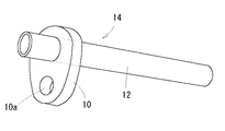
以下、本発明のもっとも好ましい実施例を、図面によって説明する。図1は本発明の実施である異形板状部材たるブラケット10の使用状態を示すものであり、ブラケット10に鋼管12をろう付けして構成した車両用燃料配管部材14を示す。ここで、10aは配管部材14を車両の枠体取付けるためのボルト孔である。
The most preferred embodiments of the present invention will be described below with reference to the drawings. FIG. 1 shows a use state of a
ブラケット10は、図2で示すように、大きい円弧10bと小さい円弧10cとを直線10d、10dで結んだ略卵形の輪郭をもつ板状の部材である。そして、両円弧10b、10cと同芯に、鋼管12のための大きい透孔10eと、前記ボルト孔10aとが穿孔されている。
As shown in FIG. 2, the
なお、ブラケット10は後述するように、素材を2個の平面によって挟圧して板状に成形されているので、その輪郭は、板厚方向の中央部がやや外方へ膨出しており、他方、板厚の両面に近い所は金型との摩擦のため、やや後退した形状となり、成形の際にバリを生じない。この状態を図2(b)でやゝ誇張して書いてある。
As will be described later, the
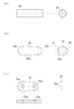
次に、ブラケット10の製造方法を説明する。まず、加工用に圧造機と、素材として鋼線の巻き線を準備する。そして、巻き線を切断して図3(a)で示すように、素材のビレット20を作る。なお、この準備工程は従来、鋼線を利用する場合に慣用されているビレットの製造手段と同じであり、詳細な説明を省略する。
Next, a method for manufacturing the
前記ビレット20はフォーマーにセットされ、軸方向に圧縮して、中間工程を行う。中間工程は同図(b)で示すように、当初のビレット20よりやや太い部分のある半成形品22を成形する。半成形品22は断面形状が円形をなし、その外形線22aは製品の輪郭とほぼ対応して一端がやゝ大径に、他端がやゝ小径に造られ、端部22bはそれぞれ半球形に丸めたものとなっている。
The
ついで圧造工程を行う。ここでは図(b)中、2点鎖線で示すように前記半成形品22の外径部を金型の平坦な面23、24の間で挟圧して板状に押しつぶす。なお、前記金型の平坦な面23には直角に伸びるピン23aが植設してあり、圧造に先立って、半成形品22へ食い込む仮工程をなし、圧造に際して半成形品22が回転して製品形状が左右非対称にならないように固定する。
Next, the forging process is performed. Here, as shown by a two-dot chain line in FIG. 2B, the outer diameter portion of the
25は前圧造工程によって得られた圧造製品であり、板厚と輪郭はほぼ製品と同形状となっている。25aは圧造工程においてピン23aによって生じた圧痕である。圧造製品25は、次いで、図示してない工程によって穿孔し、ボルト孔10aと大きい透孔10eを設けるが、このとき同時に前記圧痕25aも除去されて、図2で示す製品となるが、この穿孔以降の工程は従来の圧造法における穿孔工程と変わらないので、詳細な説明は省略する。
この実施例では、従来のプレス加工によって生産されたものの材料重量が21グラムであったものが、13グラムで足りるようになり、8グラムの節約になった。 In this example, what was produced by conventional press working and had a material weight of 21 grams was now 13 grams, saving 8 grams.
この発明はブラケットやステイの製造に限定されず、伝動チェーンのリンク板など、伝動部材の製造にも適用できる。 The present invention is not limited to the manufacture of brackets and stays, but can also be applied to the manufacture of transmission members such as link plates of transmission chains.
10 ブラケット
10a ボルト孔
10b 大きい円弧
10c 小さい円弧
10d 直線
10e 大きい透孔
12 鋼管
14 車両用燃料配管部材
20 ビレット
22 半成形品
22a 外形線
22b 端部
23、24 金型の平坦な面
23a ピン
25 圧造品
25a 圧痕
DESCRIPTION OF
Claims (3)
Priority Applications (1)
| Application Number | Priority Date | Filing Date | Title |
|---|---|---|---|
| JP2006015888A JP2007196249A (en) | 2006-01-25 | 2006-01-25 | Method for manufacturing special shape plate member |
Applications Claiming Priority (1)
| Application Number | Priority Date | Filing Date | Title |
|---|---|---|---|
| JP2006015888A JP2007196249A (en) | 2006-01-25 | 2006-01-25 | Method for manufacturing special shape plate member |
Publications (1)
| Publication Number | Publication Date |
|---|---|
| JP2007196249A true JP2007196249A (en) | 2007-08-09 |
Family
ID=38451360
Family Applications (1)
| Application Number | Title | Priority Date | Filing Date |
|---|---|---|---|
| JP2006015888A Pending JP2007196249A (en) | 2006-01-25 | 2006-01-25 | Method for manufacturing special shape plate member |
Country Status (1)
| Country | Link |
|---|---|
| JP (1) | JP2007196249A (en) |
Cited By (1)
| Publication number | Priority date | Publication date | Assignee | Title |
|---|---|---|---|---|
| CN111036813A (en) * | 2019-12-12 | 2020-04-21 | 江苏亚星锚链股份有限公司 | Forging method of high-strength underwater cutting ring |
Citations (4)
| Publication number | Priority date | Publication date | Assignee | Title |
|---|---|---|---|---|
| JPS60102246A (en) * | 1983-11-09 | 1985-06-06 | Musashi Seimitsu Kogyo Kk | Manufacture of connecting rod for internal-combustion engine |
| JP2001293531A (en) * | 2000-04-12 | 2001-10-23 | Toyota Motor Corp | Inner diameter precision improving method of work and manufacturing method of cam shaft |
| JP2003285138A (en) * | 2002-01-24 | 2003-10-07 | Nissan Motor Co Ltd | Method for manufacturing cam piece for built-up cam shaft |
| JP2004019494A (en) * | 2002-06-13 | 2004-01-22 | Nissan Motor Co Ltd | Assembly type camshaft for engine, and its manufacturing method |
-
2006
- 2006-01-25 JP JP2006015888A patent/JP2007196249A/en active Pending
Patent Citations (4)
| Publication number | Priority date | Publication date | Assignee | Title |
|---|---|---|---|---|
| JPS60102246A (en) * | 1983-11-09 | 1985-06-06 | Musashi Seimitsu Kogyo Kk | Manufacture of connecting rod for internal-combustion engine |
| JP2001293531A (en) * | 2000-04-12 | 2001-10-23 | Toyota Motor Corp | Inner diameter precision improving method of work and manufacturing method of cam shaft |
| JP2003285138A (en) * | 2002-01-24 | 2003-10-07 | Nissan Motor Co Ltd | Method for manufacturing cam piece for built-up cam shaft |
| JP2004019494A (en) * | 2002-06-13 | 2004-01-22 | Nissan Motor Co Ltd | Assembly type camshaft for engine, and its manufacturing method |
Cited By (1)
| Publication number | Priority date | Publication date | Assignee | Title |
|---|---|---|---|---|
| CN111036813A (en) * | 2019-12-12 | 2020-04-21 | 江苏亚星锚链股份有限公司 | Forging method of high-strength underwater cutting ring |
Similar Documents
| Publication | Publication Date | Title |
|---|---|---|
| TWI537075B (en) | A method for making a spanner | |
| KR20060116099A (en) | Universal joint for vehicle and manufacturing method thereof | |
| EP1384537B1 (en) | Method of producing a bushing | |
| JP5446787B2 (en) | Ring material manufacturing method | |
| JP3787767B2 (en) | Method for manufacturing hooked connecting shaft | |
| JP2004330278A (en) | Pierce nut manufacturing method | |
| JP2007196249A (en) | Method for manufacturing special shape plate member | |
| JP3331499B2 (en) | Bush processing method | |
| KR101473948B1 (en) | Method for manufacturing flange structure | |
| JP2010042440A (en) | Method of manufacturing grooved bolt | |
| JP2009028780A (en) | Method for manufacturing hollow-formed material | |
| JP2013202690A (en) | Plastic working method of tubular part | |
| KR19990046098A (en) | Method For Manufacturing Bolt With Flange | |
| CN107008838A (en) | A kind of countersunk head hexagon socket head cap screw manufacturing process | |
| KR20120037645A (en) | Method of making a washer | |
| KR100426334B1 (en) | manufacturing method of nipple for the wheel | |
| JP2001321867A (en) | Method for forming bolt hole in steel wheel | |
| JPH0658124B2 (en) | Yoke for universal joints | |
| JP3513818B2 (en) | Manufacturing method of nut with washer | |
| JP2008119731A (en) | Method of manufacturing center-bulged plate member with large thickness | |
| CN211027937U (en) | A blocker for turning to seat | |
| JP5008189B2 (en) | Gear forming method and apparatus | |
| JP2004351436A (en) | Forming method and forming die | |
| JP2006346704A (en) | Method for manufacturing nut | |
| KR100510016B1 (en) | a manufacturing method of a bolt for the brake lining |
Legal Events
| Date | Code | Title | Description |
|---|---|---|---|
| RD03 | Notification of appointment of power of attorney |
Effective date: 20070907 Free format text: JAPANESE INTERMEDIATE CODE: A7423 |
|
| A621 | Written request for application examination |
Free format text: JAPANESE INTERMEDIATE CODE: A621 Effective date: 20081031 |
|
| A977 | Report on retrieval |
Free format text: JAPANESE INTERMEDIATE CODE: A971007 Effective date: 20100609 |
|
| A131 | Notification of reasons for refusal |
Effective date: 20110712 Free format text: JAPANESE INTERMEDIATE CODE: A131 |
|
| A02 | Decision of refusal |
Effective date: 20111206 Free format text: JAPANESE INTERMEDIATE CODE: A02 |