JP2007192529A - Cooling module - Google Patents
Cooling module Download PDFInfo
- Publication number
- JP2007192529A JP2007192529A JP2006189268A JP2006189268A JP2007192529A JP 2007192529 A JP2007192529 A JP 2007192529A JP 2006189268 A JP2006189268 A JP 2006189268A JP 2006189268 A JP2006189268 A JP 2006189268A JP 2007192529 A JP2007192529 A JP 2007192529A
- Authority
- JP
- Japan
- Prior art keywords
- radiator
- heat exchanger
- cooling module
- bracket
- shroud
- Prior art date
- Legal status (The legal status is an assumption and is not a legal conclusion. Google has not performed a legal analysis and makes no representation as to the accuracy of the status listed.)
- Withdrawn
Links
Images


Classifications
-
- F—MECHANICAL ENGINEERING; LIGHTING; HEATING; WEAPONS; BLASTING
- F01—MACHINES OR ENGINES IN GENERAL; ENGINE PLANTS IN GENERAL; STEAM ENGINES
- F01P—COOLING OF MACHINES OR ENGINES IN GENERAL; COOLING OF INTERNAL-COMBUSTION ENGINES
- F01P3/00—Liquid cooling
- F01P3/18—Arrangements or mounting of liquid-to-air heat-exchangers
-
- B—PERFORMING OPERATIONS; TRANSPORTING
- B60—VEHICLES IN GENERAL
- B60K—ARRANGEMENT OR MOUNTING OF PROPULSION UNITS OR OF TRANSMISSIONS IN VEHICLES; ARRANGEMENT OR MOUNTING OF PLURAL DIVERSE PRIME-MOVERS IN VEHICLES; AUXILIARY DRIVES FOR VEHICLES; INSTRUMENTATION OR DASHBOARDS FOR VEHICLES; ARRANGEMENTS IN CONNECTION WITH COOLING, AIR INTAKE, GAS EXHAUST OR FUEL SUPPLY OF PROPULSION UNITS IN VEHICLES
- B60K11/00—Arrangement in connection with cooling of propulsion units
-
- F—MECHANICAL ENGINEERING; LIGHTING; HEATING; WEAPONS; BLASTING
- F01—MACHINES OR ENGINES IN GENERAL; ENGINE PLANTS IN GENERAL; STEAM ENGINES
- F01P—COOLING OF MACHINES OR ENGINES IN GENERAL; COOLING OF INTERNAL-COMBUSTION ENGINES
- F01P2070/00—Details
- F01P2070/50—Details mounting fans to heat-exchangers
-
- F—MECHANICAL ENGINEERING; LIGHTING; HEATING; WEAPONS; BLASTING
- F01—MACHINES OR ENGINES IN GENERAL; ENGINE PLANTS IN GENERAL; STEAM ENGINES
- F01P—COOLING OF MACHINES OR ENGINES IN GENERAL; COOLING OF INTERNAL-COMBUSTION ENGINES
- F01P5/00—Pumping cooling-air or liquid coolants
- F01P5/02—Pumping cooling-air; Arrangements of cooling-air pumps, e.g. fans or blowers
- F01P5/06—Guiding or ducting air to, or from, ducted fans
Landscapes
- Engineering & Computer Science (AREA)
- Chemical & Material Sciences (AREA)
- Combustion & Propulsion (AREA)
- Mechanical Engineering (AREA)
- General Engineering & Computer Science (AREA)
- Cooling, Air Intake And Gas Exhaust, And Fuel Tank Arrangements In Propulsion Units (AREA)
- Details Of Heat-Exchange And Heat-Transfer (AREA)
- Air-Conditioning For Vehicles (AREA)
Abstract
Description
本発明は、熱交換器とシュラウドとを一体に組み付けたクーリングモジュールに関する。 The present invention relates to a cooling module in which a heat exchanger and a shroud are assembled together.
従来、自動車のラジエータやコンデンサ等の熱交換器は、個別に弾性体を介して車体に搭載されていた。 Conventionally, heat exchangers such as automobile radiators and condensers have been individually mounted on the vehicle body via elastic bodies.
近年、熱交換器や車体前周りの部品を一体に組み付けてモジュールを構成して、車体に一括搭載する組立て方法が考案され、主流になりつつある。この中には、複数の熱交換器とシュラウドを一体に組み付けたクーリングモジュールがあり、種々の構造が考案されている(例えば、特許文献1参照)。 In recent years, a method of assembling a heat exchanger and parts around the front of the vehicle body to form a module and mounting them on the vehicle body has been devised and becoming mainstream. Among them, there is a cooling module in which a plurality of heat exchangers and a shroud are assembled together, and various structures have been devised (for example, see Patent Document 1).
このようなクーリングモジュールにおいて、熱交換器の車両幅方向におけるシール性向上のため、シュラウドの長手方向両端部から熱交換器側に延びる延設部をシュラウドに設ける場合がある。
しかしながら、上記のようにシュラウドに延設部を設ける場合、車両走行時の風圧等により延設部のバタツキが発生するという問題がある。 However, when the extended portion is provided in the shroud as described above, there is a problem that the extended portion flutters due to wind pressure or the like when the vehicle travels.
本発明は、上記点に鑑み、シュラウドの長手方向両端部から熱交換器側に延びる延設部を設けたクーリングモジュールにおいて、延設部のバタツキを抑制することを目的とする。 In view of the above points, an object of the present invention is to suppress fluttering of an extended portion in a cooling module provided with an extended portion that extends from both longitudinal ends of the shroud toward the heat exchanger.
上記目的を達成するため、本発明は、空気と内部を通過する熱媒体との熱交換を行う熱交換器(1)と、熱交換器(1)に他部品(2)を固定するブラケット(5)と、熱交換器(1)に空気を供給する送風機(3)を保持し、熱交換器(1)を挟んで他部品(2)と反対側に配置され、熱交換器(1)を通過する空気流をガイドするシュラウド(4)とを備えるクーリングモジュールであって、シュラウド(4)の端部は、他部品(2)側に延び、他部品(2)の側方および熱交換器(1)の側方をシールする延設部(40)として構成されており、延設部(40)は、ブラケット(5)に固定されていることを特徴としている。 In order to achieve the above object, the present invention provides a heat exchanger (1) for exchanging heat between air and a heat medium passing through the interior, and a bracket for fixing another component (2) to the heat exchanger (1) ( 5) and a blower (3) that supplies air to the heat exchanger (1), and is disposed on the opposite side of the other component (2) across the heat exchanger (1). The heat exchanger (1) And a shroud (4) for guiding an air flow passing through the end of the shroud (4) extending to the other part (2) side, and the side and heat exchange of the other part (2) It is comprised as an extension part (40) which seals the side of a container (1), and the extension part (40) is being fixed to the bracket (5).
これにより、延設部(40)をブラケット(5)に固定することができるため、延設部(40)のバタツキを抑制することが可能となる。 Thereby, since the extension part (40) can be fixed to the bracket (5), it becomes possible to suppress the fluttering of the extension part (40).
具体的には、ブラケット(5)に、延設部(40)に向かって延び、延設部(40)が固定される接合部(52)を設けてもよい。 Specifically, the bracket (5) may be provided with a joint portion (52) that extends toward the extension portion (40) and to which the extension portion (40) is fixed.
また、接合部(52)に、延設部(40)の端部が嵌合する凹部(53)を設けてもよい。 Moreover, you may provide the recessed part (53) in which the edge part of the extension part (40) fits in a junction part (52).
また、延設部(40)における接合部(52)に対応する部位に切り欠き部(41)を形成し、接合部(52)に、切り欠き部(41)と係合する係合部(54)を設けてもよい。 Moreover, a notch part (41) is formed in the site | part corresponding to the junction part (52) in an extending part (40), and the engaging part (52) engages with a notch part (41) (52). 54) may be provided.
また、熱交換器(1)と、車両内の熱交換器(1)の前方に配置されるバンパ部材の間であって、熱交換器(1)より空気流れ上流側に位置する第1の空間を、車両内の第1の空間を除く第2の空間と仕切るダクト(6)を設け、延設部(40)を、ダクト(6)を介してブラケット(5)に固定してもよい。 The first heat exchanger (1) is located between the heat exchanger (1) and the bumper member disposed in front of the heat exchanger (1) in the vehicle, and is located upstream of the heat exchanger (1). A duct (6) that partitions the space from the second space excluding the first space in the vehicle may be provided, and the extending portion (40) may be fixed to the bracket (5) via the duct (6). .
なお、上記各手段の括弧内の符号は、後述する実施形態に記載の具体的手段との対応関係を示すものである。 In addition, the code | symbol in the bracket | parenthesis of each said means shows the correspondence with the specific means as described in embodiment mentioned later.
(第1実施形態)
以下、本発明の第1実施形態について図1〜図4に基づいて説明する。本第1実施形態のクーリングモジュールは車両用であり、このクーリングモジュールは、通常、車両の前端部に搭載される。
(First embodiment)
Hereinafter, a first embodiment of the present invention will be described with reference to FIGS. The cooling module of the first embodiment is for a vehicle, and this cooling module is usually mounted at the front end of the vehicle.
図1は本第1実施形態に係るクーリングモジュールの要部を車両前方側からみた状態を示す拡大斜視図で、図2は本第1実施形態に係るクーリングモジュールの要部を車両後方側からみた状態を示す拡大斜視図である。 FIG. 1 is an enlarged perspective view showing a state in which the main part of the cooling module according to the first embodiment is seen from the front side of the vehicle, and FIG. 2 is a view of the main part of the cooling module according to the first embodiment from the rear side of the vehicle. It is an expansion perspective view which shows a state.
図1および図2に示すように、クーリングモジュールは、図示しないエンジン(内燃機関)の冷却水と空気とを熱交換させて冷却水を冷却するラジエータ1と、図示しない車両用冷凍サイクル(空調装置)内を循環する冷媒と空気とを熱交換させて冷媒を冷却するコンデンサ2と、ラジエータ1およびコンデンサ2に冷却風を送風する電動送風機3と、電動送風機3を保持するとともに、電動送風機3により誘起される空気流がラジエータ1およびコンデンサ2に流れるように空気流をガイドするシュラウド4とを備えている。
As shown in FIGS. 1 and 2, the cooling module includes a
ちなみに、コンデンサ2は、ラジエータ1よりも空気流れ上流側、換言すると、車両前方側に配置されている。シュラウド4は、ラジエータ1の空気流れ下流側(車両後方側)に配置されており、ラジエータ1の背面(車両後方側の面)を覆うようになっている。なお、ラジエータ1が本発明の熱交換器に相当し、コンデンサ2が他部品に相当し、冷却水が熱媒体に相当している。
Incidentally, the
図3は、本第1実施形態に係るラジエータ1の要部を示す拡大斜視図である。図3に示すように、ラジエータ1は、冷却水が流通する複数本のラジエータチューブからなるラジエータコア1a、およびラジエータチューブの長手方向両端側に配設されて各ラジエータチューブに連通するラジエータタンク1bを有している。
FIG. 3 is an enlarged perspective view showing a main part of the
本第1実施形態のラジエータ1は、冷却水が上下方向に流れるダウンフロー型のラジエータであって、ラジエータチューブの長手方向は鉛直方向に延びており、ラジエータタンク1bはラジエータコア1aの鉛直方向上下端部に配置されている。
The
ラジエータタンク1bの長手方向両端部には、貫通孔10がそれぞれ設けられている。貫通孔10は、ラジエータタンク1b内を貫通するように形成されている。また、ラジエータタンク1bにおいて、貫通孔10の一方の開口部はコンデンサ2が固定される側の面(車両前方側)に形成され、他方の開口部はコンデンサ2が固定される側と反対の面(車両後方側)に形成されている。すなわち、貫通孔10は、車両前方側から車両後方側に貫通している。
Through
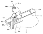
図4は、本第1実施形態に係るコンデンサ2にブラケット5を組み付けた状態を示す拡大斜視図である。図4に示すように、コンデンサ2もラジエータ1と同様に、冷媒が流通する複数本のコンデンサチューブからなるコンデンサコア2a、およびコンデンサチューブの長手方向両端側に配設されて各コンデンサチューブに連通するコンデンサタンク2bとを有している。
FIG. 4 is an enlarged perspective view showing a state in which the
本第1実施形態のコンデンサ2は、コンデンサチューブの長手方向は水平方向に延びており、コンデンサタンク2bはコンデンサコア2aの水平方向両端部に配置されている。
In the
また、コンデンサ2の鉛直方向上面および下面には、樹脂製のブラケット5が組み付けられている。本第1実施形態では、コンデンサタンク2b近傍に鉛直方向に突出するピン2cを設定し、このピン2cをブラケット5に設けられた穴部5aに挿入することにより、ブラケット5はコンデンサ2に組み付けられている。
ブラケット5は、コンデンサチューブの長手方向(水平方向)に延びる梁部50を有している。また、梁部50の長手方向両端部には、ラジエータ1側(車両後方側)に向かって突出する弾性変形可能な爪部51が設けられている。
The
爪部51は、ラジエータ1の貫通孔10に嵌合するように構成されており、貫通孔10の一方の開口部から挿入し、他方の開口部の角部に係合するようになっている。爪部51は、弾性変形可能な一対の係合片51a、51bから構成されている。一対の係合片51a、51bには、貫通孔10の他方の開口部の角部に係合する突起部が形成されている。
The nail |
爪部51は、貫通孔10の内壁により押圧されて一対の係合片51a、51bが弾性変形して互いに接近した状態で貫通孔10に挿入される。爪部51が貫通孔10を貫通した後には、一対の係合片51a、51bの弾性変形が戻り、突起部が他方の開口部の角部に係合するようになっている。このように爪部51が貫通孔10に係合することにより、コンデンサ2はラジエータ1に固定されている。
The
図1に戻り、シュラウド4には、シュラウド4の長手方向(車両幅方向)両端部からラジエータ1およびコンデンサ2側(車両前方側)に延びる延設部40が設けられている。延設部40によって、ラジエータ1およびコンデンサ2の車両幅方向はシールされ、流入空気がラジエータ1およびコンデンサ2の側方を通過しようとするのを抑制する。
Returning to FIG. 1, the
また、ブラケット5の梁部50の長手方向(車両幅方向)両端部には、延設部40に向かって延びる接合部52が設けられている。接合部52の車両幅方向端部は、延設部40と嵌合するようになっており、これによりシュラウド4の延設部40がブラケット5に固定されている。また、接合部52はブラケット5と一体に成形されている。
Further, at both ends in the longitudinal direction (vehicle width direction) of the
次に、本第1実施形態における延設部40と接合部52との嵌合構造を詳細に説明する。
Next, the fitting structure between the
接合部52の車両幅方向端部には、一対の板状部材53a、53bが設けられている。一対の板状部材53a、53bは、延設部40に対して平行になるように、接合部52からコア部1a側に向かって略鉛直方向に延びている。この一対の板状部材53a、53bの間が凹部53になっており、この凹部53と延設部40の鉛直方向端部が嵌合するように構成されている。
A pair of plate-
以上説明したように、ブラケット5に凹部53を有する接合部52を設け、凹部53と延設部40の鉛直方向端部とを嵌合させることで、延設部40をブラケット5に固定することができる。このため、延設部40のバタツキを抑制することが可能となる。
As described above, the
(第2実施形態)
次に、本発明の第2実施形態について図5および図6に基づいて説明する。本第2実施形態は、上記第1実施形態に比較して、シュラウド4の延設部40とブラケット5の接合部52との嵌合構造が異なるものである。上記第1実施形態と同様の部分については同一の符号を付して説明を省略する。
(Second Embodiment)
Next, a second embodiment of the present invention will be described with reference to FIGS. The second embodiment is different from the first embodiment in the fitting structure between the
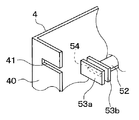
図5は本第2実施形態に係るクーリングモジュールの要部を示す拡大斜視図で、図6は図5中A部を拡大した分解斜視図である。図5および図6に示すように、本第2実施形態では、シュラウド4の延設部40は、車両上下方向(鉛直方向)においてブラケット5より外側まで延びている。また、延設部40における接合部52の車両幅方向端部に対応する部位には、車両後方側に向かって切り欠かれた切り欠き部41が形成されている。
FIG. 5 is an enlarged perspective view showing a main part of the cooling module according to the second embodiment, and FIG. 6 is an exploded perspective view in which an A portion in FIG. 5 is enlarged. As shown in FIGS. 5 and 6, in the second embodiment, the extending
接合部52の車両幅方向両端部には、一対の板状部材53a、53bが設けられている。一対の板状部材53a、53bは、それぞれ延設部40と平行になるように配置されている。接合部52における一対の板状部材53a、53b間の部位は、切り欠き部41に係合する係合部54になっている。
A pair of plate-
以上説明したように、ブラケット5に係合部54を有する接合部52を設け、延設部40に形成した切り欠き部41に係合部54を係合させることで、延設部40をブラケット5に固定することができる。このため、上記第1実施形態と同様の効果を得ることが可能となる。
As described above, the
(第3実施形態)
次に、本発明の第3実施形態について図7〜図11に基づいて説明する。上記第1実施形態と同様の部分については同一の符号を付して説明を省略する。
(Third embodiment)
Next, a third embodiment of the present invention will be described with reference to FIGS. The same parts as those in the first embodiment are denoted by the same reference numerals and description thereof is omitted.
図7は、本第3実施形態に係るクーリングモジュールを示す斜視図である。図7に示すように、本実施形態のクーリングモジュールはダクト6を備えている。ダクト6は、クーリングモジュールより車両前方側に搭載されるバンパ部材(図示せず)とクーリングモジュールとの間の第1の空間と、その周囲の第2の空間とを仕切るように配置されている。
FIG. 7 is a perspective view showing a cooling module according to the third embodiment. As shown in FIG. 7, the cooling module of this embodiment includes a
ダクト6は、上方側に位置して水平方向に延びる上方部材61、下方側に位置して水平方向に延びる下方部材62、および上下方向に延びて上方部材61および下方部材62を連結する側方部材63からなっている。上方部材61および下方部材62によって、第1の空間と第2の空間とが鉛直方向で仕切られている。また、側方部材63によって、第1の空間と第2の空間とが車両幅方向で仕切られている。
The
上方部材61および下方部材62には、ブラケット5の梁部50に対向する接続部材64が一体に成形されている。接続部材64は、上方部材61および下方部材62の空気流れ下流側の端部から、それぞれラジエータチューブ長手方向外側に向かって延びている。すなわち、上方部材61の接続部材64は鉛直方向上方側に向かって延びており、下方部材62の接続部材64は鉛直方向下方側に向かって延びている。
The
図8は、本第3実施形態に係るクーリングモジュールの要部を示す拡大斜視図である。図7および図8に示すように、ダクト6における上方部材61および下方部材62の接続部材64の長手方向両端部には、貫通穴部640がそれぞれ形成されている。貫通穴部640は、車両前方側から車両後方側に貫通している。
FIG. 8 is an enlarged perspective view showing a main part of the cooling module according to the third embodiment. As shown in FIGS. 7 and 8, through
また、ブラケット5の長手方向両端部には、ダクト6側(車両前方側)に向かって突出する弾性変形可能なダクト用爪部55が設けられている。
Further, elastically deformable
図9は、図8のB部拡大図である。図9に示すように、ダクト用爪部55は、ダクト6における接続部材64の貫通穴部640に嵌合するように構成されており、貫通穴部640の一方の開口部から挿入し、他方の開口部の角部に係合するようになっている。ダクト用爪部55は、弾性変形可能な一対の係合片55a、55bから構成されている。一対の係合片55a、55bには、貫通穴部640の他方の開口部の角部に係合する突起部が形成されている。
FIG. 9 is an enlarged view of a portion B in FIG. As shown in FIG. 9, the
ダクト用爪部55は、貫通穴部640の内壁により押圧されて一対の係合片55a、55bが弾性変形して互いに接近した状態で貫通穴部640に挿入される。ダクト用爪部55が貫通穴部640を貫通した後には、一対の係合片55a、55bの弾性変形が戻り、突起部が他方の開口部の角部に係合するようになっている。このように、ダクト用爪部55が貫通穴部640に係合することにより、ダクト6の上方部材61および下方部材62は、ブラケット5に固定される。
The
図7に戻り、シュラウド4の延設部40には、車両幅方向の断面形状が略L字型の鉤部42が2つ設けられている。
Returning to FIG. 7, the extending
図10は図8のC部拡大図で、図11は図10の分解斜視図である。図10および図11に示すように、鉤部42は、車両幅方向外側に突出して形成され、その先端が車両前方側を向くようになっている。鉤部42において、L字型の長辺部42aが延設部40の板面に対して平行になっている。また、鉤部42と延設部40の車両幅方向外側の面との隙間(以下、受入部42bという)は、ダクト6の側方部材63の厚みに対応している。また、本実施形態では、鉤部42は延設部40と一体に成形されている。
10 is an enlarged view of a portion C in FIG. 8, and FIG. 11 is an exploded perspective view of FIG. As shown in FIGS. 10 and 11, the
また、ダクト6の側方部材63は、鉤部42で係止される2つの被係止部630を有している。被係止部630は、車両後方側に突出して形成されている。被係止部630には、鉛直方向下方側から上方側に切り欠いた切り欠き部630aが設けられている。この切り欠き部630aの空気流れ方向(車両前後方向)の長さは、鉤部42のL時型の短辺部42cの厚みに対応している。また、本実施形態では、被係止部630は側方部材63と一体に成形されている。
Further, the
そして、延設部40の受入部42bに、側方部材63を鉛直方向上側からスライドさせ、被係止部の630の切り欠き部630aを、鉤部42のL字型の短辺部42cに係止させる。このようにして、ダクト6の側方部材63は、シュラウド4の延設部40に固定される。
Then, the
以上説明したように、ダクト6の上方部材61および下方部材62をブラケット5に固定するとともに、ダクト6の側方部材63をシュラウド4の延設部40に固定することで、延設部40を、ダクト6を介してブラケット5に固定することができる。このため、延設部40のバタツキを抑制することが可能となる。
As described above, the
(第4実施形態)
次に、本発明の第4実施形態について図12に基づいて説明する。上記第3実施形態と同様の部分については同一の符号を付して説明を省略する。
(Fourth embodiment)
Next, a fourth embodiment of the present invention will be described with reference to FIG. The same parts as those in the third embodiment are denoted by the same reference numerals and description thereof is omitted.
図12は、本第4実施形態に係るクーリングモジュールを示す斜視図である。図12に示すように、本実施形態のダクト6の上方部材61および下方部材62は、車両幅方向においてそれぞれ2つに分割されている。より詳細には、上方部材61の車両幅方向における2つの貫通穴部640間の部位が廃止されており、同様に下方部材62の車両幅方向における2つの貫通穴部640間の部位が廃止されている。このような構成にしても、上記第3実施形態と同様の効果を得ることができる。
FIG. 12 is a perspective view showing a cooling module according to the fourth embodiment. As shown in FIG. 12, the
(第5実施形態)
次に、本発明の第5実施形態について図13に基づいて説明する。上記第3実施形態と同様の部分については同一の符号を付して説明を省略する。
(Fifth embodiment)
Next, a fifth embodiment of the present invention will be described with reference to FIG. The same parts as those in the third embodiment are denoted by the same reference numerals and description thereof is omitted.
図13は、本第5実施形態に係るクーリングモジュールを示す斜視図である。図13に示すように、本実施形態では、ブラケット5の梁部50が廃止されている。また、ダクト6における上方部材61および下方部材62の接続部材64には、2つのブラケット5を繋ぐようにコンデンサチューブ長手方向(車両幅方向)に延びるシール部材65が一体に成形されている。このような構成にしても、上記第3実施形態と同様の効果を得ることができる。
FIG. 13 is a perspective view showing a cooling module according to the fifth embodiment. As shown in FIG. 13, in this embodiment, the
(第6実施形態)
次に、本発明の第6実施形態について図14に基づいて説明する。上記第4実施形態と同様の部分については同一の符号を付して説明を省略する。
(Sixth embodiment)
Next, a sixth embodiment of the present invention will be described with reference to FIG. The same parts as those in the fourth embodiment are denoted by the same reference numerals and description thereof is omitted.
図14は、本第6実施形態に係るクーリングモジュールを示す斜視図である。図14に示すように、本実施形態では、ブラケット5の梁部50が廃止されている。このような構成にしても、上記第4実施形態と同様の効果を得ることができる。
FIG. 14 is a perspective view showing a cooling module according to the sixth embodiment. As shown in FIG. 14, in this embodiment, the
(他の実施形態)
なお、上記各実施形態では、冷却水が上下方向に流れるダウンフロー型のラジエータ1に本発明を適用した実施形態について述べたが、冷却水が水平方向に流れるクロスフロー型のラジエータに本発明を適用することもできる。
(Other embodiments)
In each of the above embodiments, the embodiment in which the present invention is applied to the
また、上記各実施形態では、他部品としてコンデンサ2を適用したが、これに限らず、例えばインタークーラ等の他の部品を適用してもよい。
Moreover, in each said embodiment, although the capacitor |
また、上記各実施形態では、ラジエータ1にコンデンサ2を固定するために、ラジエータ1に設けた貫通孔10と、コンデンサ2に設けたブラケット5の爪部51とを嵌合させる方法を適用したが、これに限らず、例えばラジエータに設けた爪部と、コンデンサに設けたブラケットの貫通孔とを嵌合させる方法を適用してもよい。
In each of the above embodiments, a method of fitting the through
また、上記各実施形態では、コンデンサ2にブラケット5を組み付けるために、コンデンサタンク2bに設けられたピン2cをブラケット5に設けられた穴部5aに挿入する方法を適用したが、これに限らず、嵌合やボルト締め等の他の方法を適用してもよい。
In each of the above embodiments, in order to assemble the
また、上記第3〜第6実施形態では、延設部40に側方部材60を固定するために、切り欠き部630aを鉤部42のL字型の短辺部42cに係止させる方法を適用したが、これに限らず、ボルト締め等の他の方法を適用してもよい。
Moreover, in the said 3rd-6th embodiment, in order to fix the side member 60 to the extending
また、上記第3〜第6実施形態では、鉤部42および被係止部630を2つずつ設けたが、これに限らず、1つでもよいし、3つ以上設けてもよい。
Moreover, in the said 3rd-6th embodiment, although the
また、上記第3〜第6実施形態において、ラジエータ1、コンデンサ2、送風機3およびシュラウド4のモジュールを車両搭載後、ダクト6をシュラウド4(延設部40)とブラケット5に組み付けるようにしてもよい。
In the third to sixth embodiments, after the
また、上記第3〜第6実施形態において、ダクト6の上方部材61と側方部材63は、一体のように図示されているが、これに限らず、車両搭載上の都合により分割してもよい。ただし、車両搭載後は上方部材61と側方部材63は何らかの方法で固定される。同様に、ダクト6の下方部材62と側方部材63を分割してもよい。
Moreover, in the said 3rd-6th embodiment, although the
1…ラジエータ(熱交換器)、2…コンデンサ(他部品)、3…送風機、4…シュラウド、5…ブラケット、6…ダクト、40…延設部、41…切り欠き部、52…接合部、53…凹部、54…係合部。
DESCRIPTION OF
Claims (5)
前記シュラウド(4)の端部は、前記他部品(2)側に延び、前記他部品(2)の側方および前記熱交換器(1)の側方をシールする延設部(40)として構成されており、
前記延設部(40)は、前記ブラケット(5)に固定されていることを特徴とするクーリングモジュール。 A heat exchanger (1) for exchanging heat between air and a heat medium passing through the interior; a bracket (5) for fixing another component (2) to the heat exchanger (1); and the heat exchanger (1 The air flow passing through the heat exchanger (1) is held by holding the blower (3) that supplies air to the other part (2) and sandwiching the heat exchanger (1). A cooling module comprising a shroud (4) for guiding,
An end portion of the shroud (4) extends to the other component (2) side, and serves as an extended portion (40) that seals the side of the other component (2) and the side of the heat exchanger (1). Configured,
The said extended part (40) is being fixed to the said bracket (5), The cooling module characterized by the above-mentioned.
前記接合部(52)には、前記切り欠き部(41)と係合する係合部(54)が設けられていることを特徴とする請求項2に記載のクーリングモジュール。 A cutout portion (41) is formed in a portion corresponding to the joint portion (52) in the extended portion (40),
The cooling module according to claim 2, wherein the joint portion (52) is provided with an engagement portion (54) that engages with the notch portion (41).
前記延設部(40)は、前記ダクト(6)を介して前記ブラケット(5)に固定されていることを特徴とする請求項1に記載のクーリングモジュール。
The first located between the heat exchanger (1) and a bumper member disposed in front of the heat exchanger (1) in the vehicle, upstream of the heat exchanger (1). A duct (6) for partitioning the space from the second space excluding the first space in the vehicle,
The cooling module according to claim 1, wherein the extended portion (40) is fixed to the bracket (5) via the duct (6).
Priority Applications (2)
| Application Number | Priority Date | Filing Date | Title |
|---|---|---|---|
| JP2006189268A JP2007192529A (en) | 2005-12-20 | 2006-07-10 | Cooling module |
| DE200610060085 DE102006060085A1 (en) | 2005-12-20 | 2006-12-19 | Cooling module for motor vehicle has radiator, holding clamp, fan and cover, radiator being between cover and other components |
Applications Claiming Priority (2)
| Application Number | Priority Date | Filing Date | Title |
|---|---|---|---|
| JP2005365738 | 2005-12-20 | ||
| JP2006189268A JP2007192529A (en) | 2005-12-20 | 2006-07-10 | Cooling module |
Publications (1)
| Publication Number | Publication Date |
|---|---|
| JP2007192529A true JP2007192529A (en) | 2007-08-02 |
Family
ID=38109069
Family Applications (1)
| Application Number | Title | Priority Date | Filing Date |
|---|---|---|---|
| JP2006189268A Withdrawn JP2007192529A (en) | 2005-12-20 | 2006-07-10 | Cooling module |
Country Status (2)
| Country | Link |
|---|---|
| JP (1) | JP2007192529A (en) |
| DE (1) | DE102006060085A1 (en) |
Cited By (4)
| Publication number | Priority date | Publication date | Assignee | Title |
|---|---|---|---|---|
| CN103747973A (en) * | 2011-06-20 | 2014-04-23 | 雷诺股份公司 | Method and device for assembling motor-fan unit and radiator for motor vehicle engine and obtained motor-fan unit and radiator assembly |
| JP2018001998A (en) * | 2016-07-04 | 2018-01-11 | スズキ株式会社 | Vehicular shroud |
| US10252611B2 (en) | 2015-01-22 | 2019-04-09 | Ford Global Technologies, Llc | Active seal arrangement for use with vehicle condensers |
| FR3132139A1 (en) * | 2022-01-25 | 2023-07-28 | Valeo Systemes Thermiques | HEAT EXCHANGER EQUIPPED WITH A MANIFOLD BOX AND THERMAL REGULATION ASSEMBLY COMPRISING SUCH A HEAT EXCHANGER |
Families Citing this family (4)
| Publication number | Priority date | Publication date | Assignee | Title |
|---|---|---|---|---|
| FR2924063B1 (en) * | 2007-11-27 | 2010-04-09 | Peugeot Citroen Automobiles Sa | DEVICE FOR REMOVABLE FIXING OF ANTI-RECYCLING WINDING ON A AIR CONDITIONING CONDENSER FOR A VEHICLE |
| DE102009056508A1 (en) | 2009-12-02 | 2011-06-09 | Behr Gmbh & Co. Kg | Cooling module and adapter pair for modular unification |
| FR2990655B1 (en) * | 2012-05-16 | 2014-05-23 | Peugeot Citroen Automobiles Sa | COOLING DEVICE FOR A MOTOR-PROPELLER GROUP OF A HYBRID VEHICLE, WITH RADIATORS AND SOLIDARIZATION MEANS ADAPTED TO BEAM DILATIONS |
| FR3104496B1 (en) * | 2019-12-13 | 2022-08-05 | Valeo Systemes Thermiques | Motor vehicle cooling module |
-
2006
- 2006-07-10 JP JP2006189268A patent/JP2007192529A/en not_active Withdrawn
- 2006-12-19 DE DE200610060085 patent/DE102006060085A1/en not_active Ceased
Cited By (5)
| Publication number | Priority date | Publication date | Assignee | Title |
|---|---|---|---|---|
| CN103747973A (en) * | 2011-06-20 | 2014-04-23 | 雷诺股份公司 | Method and device for assembling motor-fan unit and radiator for motor vehicle engine and obtained motor-fan unit and radiator assembly |
| US10252611B2 (en) | 2015-01-22 | 2019-04-09 | Ford Global Technologies, Llc | Active seal arrangement for use with vehicle condensers |
| JP2018001998A (en) * | 2016-07-04 | 2018-01-11 | スズキ株式会社 | Vehicular shroud |
| FR3132139A1 (en) * | 2022-01-25 | 2023-07-28 | Valeo Systemes Thermiques | HEAT EXCHANGER EQUIPPED WITH A MANIFOLD BOX AND THERMAL REGULATION ASSEMBLY COMPRISING SUCH A HEAT EXCHANGER |
| WO2023143898A1 (en) * | 2022-01-25 | 2023-08-03 | Valeo Systemes Thermiques | Heat exchanger provided with a collecting box and thermal control assembly comprising such a heat exchanger |
Also Published As
| Publication number | Publication date |
|---|---|
| DE102006060085A1 (en) | 2007-06-28 |
Similar Documents
| Publication | Publication Date | Title |
|---|---|---|
| JP2007192529A (en) | Cooling module | |
| JP2007326431A (en) | Seal duct | |
| US6883589B2 (en) | Front end structure | |
| JP2001121941A (en) | On-vehicle mounting structure of heat exchanger | |
| KR19980018615A (en) | Integral heat exchanger | |
| WO2013099166A1 (en) | Heat exchanger mounting structure | |
| KR20010085507A (en) | Heat-exchange module, especially for a motor vehicle | |
| JP2007101088A (en) | Tank structure for heat exchanger | |
| JP4907152B2 (en) | Radiator core support | |
| JP2001278115A (en) | Front end structure of vehicle | |
| KR102548211B1 (en) | Integrated radiator and method of assembling thereof | |
| US6607025B2 (en) | Heat-exchange module for a motor vehicle | |
| JP2010007629A (en) | Heat exchanger for vehicle | |
| JP4447149B2 (en) | Bracket mounting structure for heat exchanger | |
| JP2008281325A (en) | Cooling module | |
| JP4665706B2 (en) | Cooling module | |
| JP6615378B2 (en) | Air conditioner outdoor unit | |
| JP2007024334A (en) | Heat exchanger | |
| JP2019199978A (en) | Heat exchanger | |
| EP1167165A1 (en) | Front end structure | |
| JP2008174093A (en) | Vehicle front structure | |
| JP2007078306A (en) | Cooling module | |
| JP2007056717A (en) | Cooling module | |
| JP2022036413A (en) | Heat exchanger for vehicle | |
| JP4207665B2 (en) | Heat exchanger mounting structure |
Legal Events
| Date | Code | Title | Description |
|---|---|---|---|
| A621 | Written request for application examination |
Free format text: JAPANESE INTERMEDIATE CODE: A621 Effective date: 20080808 |
|
| A761 | Written withdrawal of application |
Effective date: 20090218 Free format text: JAPANESE INTERMEDIATE CODE: A761 |