JP2007188773A - Fuel cell stack - Google Patents
Fuel cell stack Download PDFInfo
- Publication number
- JP2007188773A JP2007188773A JP2006006109A JP2006006109A JP2007188773A JP 2007188773 A JP2007188773 A JP 2007188773A JP 2006006109 A JP2006006109 A JP 2006006109A JP 2006006109 A JP2006006109 A JP 2006006109A JP 2007188773 A JP2007188773 A JP 2007188773A
- Authority
- JP
- Japan
- Prior art keywords
- fuel cell
- cell stack
- end plate
- mount
- communication hole
- Prior art date
- Legal status (The legal status is an assumption and is not a legal conclusion. Google has not performed a legal analysis and makes no representation as to the accuracy of the status listed.)
- Pending
Links
Images
Classifications
-
- Y—GENERAL TAGGING OF NEW TECHNOLOGICAL DEVELOPMENTS; GENERAL TAGGING OF CROSS-SECTIONAL TECHNOLOGIES SPANNING OVER SEVERAL SECTIONS OF THE IPC; TECHNICAL SUBJECTS COVERED BY FORMER USPC CROSS-REFERENCE ART COLLECTIONS [XRACs] AND DIGESTS
- Y02—TECHNOLOGIES OR APPLICATIONS FOR MITIGATION OR ADAPTATION AGAINST CLIMATE CHANGE
- Y02E—REDUCTION OF GREENHOUSE GAS [GHG] EMISSIONS, RELATED TO ENERGY GENERATION, TRANSMISSION OR DISTRIBUTION
- Y02E60/00—Enabling technologies; Technologies with a potential or indirect contribution to GHG emissions mitigation
- Y02E60/30—Hydrogen technology
- Y02E60/50—Fuel cells
Landscapes
- Fuel Cell (AREA)
Abstract
【課題】エンドプレート自体の剛性を有効に利用してマウント部を構成することができ、所望の取り付け部位に強固且つ確実に保持することを可能にする。
【解決手段】燃料電池スタック10は、複数の単位セル12が積層された積層体14をケーシング24内に収容する。ケーシング24を構成するエンドプレート20a、20bには、燃料電池スタック10を取り付け部位に固定するためのマウント部80が4個所に設けられる。マウント部80は、該マウント部80に付与される荷重をエンドプレート20a、20bの面方向に分散可能な梁部82を設ける。
【選択図】図4
A mount portion can be configured by effectively utilizing the rigidity of an end plate itself, and can be firmly and securely held at a desired attachment site.
A fuel cell stack accommodates a laminated body in which a plurality of unit cells are laminated in a casing. The end plates 20a and 20b constituting the casing 24 are provided with four mount portions 80 for fixing the fuel cell stack 10 to the attachment site. The mount portion 80 is provided with a beam portion 82 that can disperse a load applied to the mount portion 80 in the surface direction of the end plates 20a and 20b.
[Selection] Figure 4
Description
本発明は、一対の電極が電解質の両側に設けられた電解質・電極構造体と、セパレータとが複数積層された積層体を、積層方向両端部に配置されるエンドプレート間に締め付け保持する燃料電池スタックに関する。 The present invention relates to a fuel cell in which an electrolyte / electrode structure in which a pair of electrodes are provided on both sides of an electrolyte and a laminate in which a plurality of separators are laminated are clamped and held between end plates arranged at both ends in the lamination direction. Regarding the stack.
例えば、固体高分子型燃料電池は、高分子イオン交換膜からなる電解質膜(電解質)を採用している。この電解質膜の両側に、それぞれカーボンを主体とする基材に貴金属系の電極触媒層を接合したアノード側電極及びカソード側電極を対設した電解質膜・電極構造体を、セパレータにより挟持して燃料電池が構成されている。 For example, a polymer electrolyte fuel cell employs an electrolyte membrane (electrolyte) made of a polymer ion exchange membrane. An electrolyte membrane / electrode structure having an anode side electrode and a cathode side electrode in which a noble metal-based electrode catalyst layer is bonded to a base material mainly composed of carbon is sandwiched by a separator on both sides of the electrolyte membrane. A battery is configured.
通常、燃料電池は、所望の発電力を得るために、所定数(例えば、数十〜数百)だけ積層した燃料電池スタックとして使用されている。この燃料電池スタックは、燃料電池の内部抵抗の増大や反応ガスのシール性の低下等を阻止するために、積層されている各燃料電池同士を確実に加圧保持する必要がある。 Usually, a fuel cell is used as a fuel cell stack in which a predetermined number (for example, several tens to several hundreds) is stacked in order to obtain a desired power generation. In this fuel cell stack, the stacked fuel cells need to be reliably pressurized and held in order to prevent an increase in the internal resistance of the fuel cell and a decrease in the sealing performance of the reaction gas.
そこで、例えば、特許文献1の燃料電池スタックが知られている。この燃料電池スタックは、図9に示すように、複数の単位セル1を積層した積層体2を備えるとともに、この積層体2の積層方向両端にエンドプレート3、3を介装して補助プレート4a、4bが配設されている。
Therefore, for example, a fuel cell stack of Patent Document 1 is known. As shown in FIG. 9, the fuel cell stack includes a stacked body 2 in which a plurality of unit cells 1 are stacked, and an
積層体2の両側部に沿って、一対の締結バンド5、5が配置されている。締結バンド5、5及び補助プレート4a、4bの端部には、円筒状のボス部6がそれぞれの孔部が一直線上に並ぶように設けられている。そして、各ボス部6に金属ピン7が挿入されることにより、締結バンド5、5及び補助プレート4a、4bが一体的に連結されている。
A pair of
補助プレート4aには、複数のボルト8が螺合する一方、補助プレート4bには、複数の皿ばね9が配設されている。従って、ボルト8が螺入されると、エンドプレート3が下方に押圧されるとともに、補助プレート4bに配置された皿ばね9が圧縮され、一対のエンドプレート3を介して積層体2に必要な締結圧が付与される、としている。
A plurality of bolts 8 are screwed onto the
ところで、上記の特許文献1では、燃料電池スタックを車両等に搭載する場合、比較的肉厚で高剛性を有する補助プレート4a、4bでマウント構造を兼用することが考えられる。例えば、補助プレート4a、4bの側部に、外方に突出するマウント部を設け、このマウント部を車両側取り付け部に固定する構成が考えられる。
By the way, in the above-mentioned Patent Document 1, when the fuel cell stack is mounted on a vehicle or the like, it is conceivable that the
しかしながら、車両の走行状態等によりマウント部に曲げ荷重等が付与される際、補助プレート4a、4bと前記マウント部との境界部位に前記曲げ荷重等が集中し易く、前記補助プレート4a、4b自体の剛性を有効に利用することができないという問題がある。これにより、燃料電池スタックを所望の取り付け部位に強固且つ正確に保持することが困難になるという問題がある。
However, when a bending load or the like is applied to the mount portion depending on the traveling state of the vehicle, the bending load or the like tends to concentrate on the boundary portion between the
本発明はこの種の問題を解決するものであり、エンドプレート自体の剛性を有効に利用してマウント部を構成することができ、所望の取り付け部位に強固且つ確実に保持することが可能な燃料電池スタックを提供することを目的とする。 The present invention solves this type of problem, and the mount part can be configured by effectively utilizing the rigidity of the end plate itself, and can be firmly and securely held at a desired attachment site. An object is to provide a battery stack.
本発明は、一対の電極が電解質の両側に設けられた電解質・電極構造体と、セパレータとが複数積層された積層体を、積層方向両端部に配置されるエンドプレート間に締め付け保持する燃料電池スタックに関するものである。 The present invention relates to a fuel cell in which an electrolyte / electrode structure in which a pair of electrodes are provided on both sides of an electrolyte and a laminate in which a plurality of separators are laminated are clamped and held between end plates arranged at both ends in the lamination direction. It is about the stack.
エンドプレートには、燃料電池スタックを取り付け部位に固定するためのマウント部が設けられるとともに、前記マウント部は、該マウント部に付与される荷重を前記エンドプレートの面方向に分散可能な梁部を設けている。また、エンドプレートには、マウント部が少なくとも3個所に設けられることが好ましい。 The end plate is provided with a mount portion for fixing the fuel cell stack to the attachment site, and the mount portion has a beam portion that can disperse the load applied to the mount portion in the surface direction of the end plate. Provided. Moreover, it is preferable that the end plate is provided with at least three mounting portions.
さらに、梁部は、エンドプレートの面から厚さ方向に膨出する肉圧部により構成されることが好ましい。さらにまた、梁部は、エンドプレートに取り付けられる別部材で構成されることが好ましい。 Furthermore, it is preferable that the beam portion is constituted by a meat pressure portion that bulges in the thickness direction from the surface of the end plate. Furthermore, it is preferable that a beam part is comprised with another member attached to an end plate.
また、燃料電池スタックは、積層体を収容するケーシングを備え、前記ケーシングは、端板であるエンドプレートと、前記積層体の側部に配置される複数の側板とを備えることが好ましい。 The fuel cell stack preferably includes a casing that accommodates the stacked body, and the casing preferably includes an end plate that is an end plate and a plurality of side plates that are disposed on a side portion of the stacked body.
本発明によれば、マウント部に曲げ荷重等が付与された際に、前記マウント部に設けられている梁部を介して前記曲げ荷重等がエンドプレートの面方向に分散される。このため、マウント部に荷重が集中することがなく、前記エンドプレート自体の剛性により該荷重を良好に受けることができる。これにより、簡単な構成で、燃料電池スタックを所望の取り付け部位に対して強固且つ確実に保持することが可能になる。 According to the present invention, when a bending load or the like is applied to the mount portion, the bending load or the like is dispersed in the surface direction of the end plate via the beam portion provided in the mount portion. For this reason, the load does not concentrate on the mount portion, and the load can be favorably received by the rigidity of the end plate itself. This makes it possible to hold the fuel cell stack firmly and securely with respect to a desired attachment site with a simple configuration.
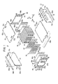
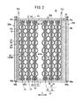
図1は、本発明の第1の実施形態に係る燃料電池スタック10の一部分解概略斜視図であり、図2は、前記燃料電池スタック10の一部断面側面図である。
FIG. 1 is a partially exploded schematic perspective view of a
図1に示すように、燃料電池スタック10は、複数の単位セル12が水平方向(矢印A方向)に積層された積層体14を備える。積層体14の積層方向(矢印A方向)一端には、ターミナルプレート16a、絶縁プレート18及びエンドプレート20aが外方に向かって、順次、配設される。積層体14の積層方向他端には、ターミナルプレート16b、絶縁性スペーサ部材22及びエンドプレート20bが外方に向かって、順次、配設される。燃料電池スタック10は、略四角形に構成されるエンドプレート20a、20bを端板として含む箱状ケーシング24により一体的に保持される。
As shown in FIG. 1, the
スペーサ部材22は、積層体14の積層方向の長さ変動を吸収して前記積層体14に所望の締め付け荷重を付与可能にするために、厚さが調整される。なお、積層体14の積層方向の長さの変動が、後述する第1及び第2金属セパレータ32、34自体の弾性等で吸収可能であれば、スペーサ部材22を用いなくてもよい。
The
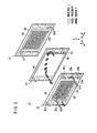
図2及び図3に示すように、各単位セル12は、電解質膜・電極構造体(電解質・電極構造体)30と、前記電解質膜・電極構造体30を挟持する薄板波形状の第1及び第2金属セパレータ32、34とを備える。
As shown in FIGS. 2 and 3, each
単位セル12の水平方向(図3中、矢印B方向)の一端縁部には、矢印A方向に互いに連通して、酸化剤ガス、例えば、酸素含有ガスを供給するための酸化剤ガス供給連通孔36a、冷却媒体を供給するための冷却媒体供給連通孔38a、及び燃料ガス、例えば、水素含有ガスを排出するための燃料ガス排出連通孔40bが設けられる。
One end edge of the
単位セル12の水平方向の他端縁部には、矢印A方向に互いに連通して、燃料ガスを供給するための燃料ガス供給連通孔40a、冷却媒体を排出するための冷却媒体排出連通孔38b、及び酸化剤ガスを排出するための酸化剤ガス排出連通孔36bが設けられる。
At the other end edge of the
電解質膜・電極構造体30は、例えば、パーフルオロスルホン酸の薄膜に水が含浸された固体高分子電解質膜42と、前記固体高分子電解質膜42を挟持するアノード側電極44及びカソード側電極46とを備える。
The electrolyte membrane /
アノード側電極44及びカソード側電極46は、カーボンペーパ等からなるガス拡散層(図示せず)と、白金合金が表面に担持された多孔質カーボン粒子が前記ガス拡散層の表面に一様に塗布されて形成された電極触媒層(図示せず)とを有する。電極触媒層は、固体高分子電解質膜42の両面に形成される。
The
第1金属セパレータ32の電解質膜・電極構造体30に向かう面32aには、燃料ガス供給連通孔40aと燃料ガス排出連通孔40bとを連通する燃料ガス流路48が形成される。この燃料ガス流路48は、例えば、矢印B方向に延在する複数本の溝部により構成される。第1金属セパレータ32の面32bには、冷却媒体供給連通孔38aと冷却媒体排出連通孔38bとを連通する冷却媒体流路50が形成される。この冷却媒体流路50は、矢印B方向に延在する複数本の溝部により構成される。
A fuel
第2金属セパレータ34の電解質膜・電極構造体30に向かう面34aには、例えば、矢印B方向に延在する複数本の溝部からなる酸化剤ガス流路52が設けられるとともに、この酸化剤ガス流路52は、酸化剤ガス供給連通孔36aと酸化剤ガス排出連通孔36bとに連通する。第2金属セパレータ34の面34bには、第1金属セパレータ32の面32bと重なり合って冷却媒体流路50が一体的に形成される。
The
第1金属セパレータ32の面32a、32bには、この第1金属セパレータ32の外周端部を周回して第1シール部材54が一体成形される。第1シール部材54は、面32aで燃料ガス供給連通孔40a、燃料ガス排出連通孔40b及び燃料ガス流路48を囲繞してこれらを連通させる一方、面32bで冷却媒体供給連通孔38a、冷却媒体排出連通孔38b及び冷却媒体流路50を囲繞してこれらを連通させる。
A
第2金属セパレータ34の面34a、34bには、この第2金属セパレータ34の外周端部を周回して第2シール部材56が一体成形される。第2シール部材56は、面34aで酸化剤ガス供給連通孔36a、酸化剤ガス排出連通孔36b及び酸化剤ガス流路52を囲繞してこれらを連通させる一方、面34bで冷却媒体供給連通孔38a、冷却媒体排出連通孔38b及び冷却媒体流路50を囲繞してこれらを連通させる。図2に示すように、第1及び第2シール部材54、56間には、固体高分子電解質膜42の外周が直接ケーシング24に接触することを阻止すべく、シール57が介装される。
A
図1及び図2に示すように、ターミナルプレート16a、16bの端部には、面方向に突出する板状の端子部58a、58bが形成される。端子部58a、58bには、例えば、走行用モータ等の負荷が接続される。
As shown in FIGS. 1 and 2, plate-like
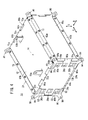
ケーシング24は、図1に示すように、端板であるエンドプレート20a、20bと、積層体14の側部に配置される複数の側板60a〜60dと、前記側板60a〜60dの互いに近接する端部同士を連結するアングル部材(例えば、Lアングル)62a〜62dと、前記エンドプレート20a、20bと前記側板60a〜60dとを連結するそれぞれ長さの異なる連結ピン64a、64bとを備える。
As shown in FIG. 1, the
エンドプレート20a、20bの上下各辺には、それぞれ2つのボス部66a、66bが突出形成されるとともに、両側の各辺には、それぞれ1つのボス部66a、66bが突出形成される。
Two
積層体14の両側に配置される側板60a、60cの長手方向両端には、ボス部70a、70bが2つずつ形成される。積層体14の上下に配置される側板60b、60dの長手方向両端には、ボス部72a、72bが3つずつ形成される。
Two
側板60a、60cの各ボス部70a、70bと、エンドプレート20a、20bの両側の各辺のボス部66a、66bとが、交互に配置されるとともに、これらに短尺な連結ピン64aが一体的に挿入されて、前記側板60a、60cが前記エンドプレート20a、20bに取り付けられる。
The
同様に、側板60b、60dのボス部72a、72bと、エンドプレート20a、20bの上辺及び下辺のボス部66a、66bとが、交互に配置されるとともに、これらに長尺な連結ピン64bが一体的に挿入されて、前記側板60b、60dが前記エンドプレート20a、20bに取り付けられる。
Similarly, the
側板60a〜60dには、短手方向両端縁部にそれぞれ複数のねじ孔74が形成される一方、アングル部材62a〜62dの各辺には、前記ねじ孔74に対応して孔部76が形成される。各孔部76に挿入される各ねじ77がねじ孔74に螺合することにより、アングル部材62a〜62dを介して側板60a〜60d同士が固定される。これにより、ケーシング24が構成される(図4参照)。
The
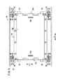
図1及び図4に示すように、エンドプレート20aには、少なくとも3箇所、第1の実施形態では、各角部に合計4箇所にマウント部80が一体に設けられる。各マウント部80は、エンドプレート20aの各角部から外方に膨出して形成されており、略板状を有する。マウント部80は、梁部82を一体に有しており、この梁部82は、エンドプレート20aの面内で該エンドプレート20aの板厚を部分的に肉厚に設定することにより構成される。
As shown in FIGS. 1 and 4, the
梁部82は、酸化剤ガス供給連通孔36a、燃料ガス排出連通孔40b、燃料ガス供給連通孔40a及び酸化剤ガス排出連通孔36bを避けて2方向(矢印B方向及び矢印C方向)に且つ互いに90°の角度を有して所定の長さだけ分岐形成される。マウント部80の先端縁部には、取り付けボルト挿入用の孔部84が矢印A方向に貫通して形成される。
The
図1に示すように、エンドプレート20bには、上記のエンドプレート20aと同様に、各角部にそれぞれ外方に向かって突出するマウント部80が一体成形されており、その詳細な説明は省略する。
As shown in FIG. 1, the
図5に示すように、燃料電池スタック10は、車両側取り付け部位86に取り付けられる。車両側取り付け部位86には、燃料電池スタック10を構成する各マウント部80に対応して支柱部88が設けられる。各支柱部88には、各マウント部80の孔部84と同軸上にねじ孔90が形成される。
As shown in FIG. 5, the
支柱部88の外方にマウント部80が配置され、このマウント部80の孔部84に取り付けボルト92が挿入される。取り付けボルト92は、支柱部88のねじ孔90に螺合しており、これによって、燃料電池スタック10は、車両側取り付け部位86に固定される。
A
このように構成される燃料電池スタック10の動作について、以下に説明する。
The operation of the
先ず、図4に示すように、燃料電池スタック10では、エンドプレート20aの酸化剤ガス供給連通孔36aに酸素含有ガス等の酸化剤ガスが供給されるとともに、燃料ガス供給連通孔40aに水素含有ガス等の燃料ガスが供給される。さらに、冷却媒体供給連通孔38aに純水やエチレングリコール、オイル等の冷却媒体が供給される。このため、積層体14では、矢印A方向に重ね合わされた複数組の単位セル12に対し、酸化剤ガス、燃料ガス及び冷却媒体が矢印A方向に供給される。
First, as shown in FIG. 4, in the
図3に示すように、酸化剤ガスは、酸化剤ガス供給連通孔36aから第2金属セパレータ34の酸化剤ガス流路52に導入され、電解質膜・電極構造体30のカソード側電極46に沿って移動する。一方、燃料ガスは、燃料ガス供給連通孔40aから第1金属セパレータ32の燃料ガス流路48に導入され、電解質膜・電極構造体30のアノード側電極44に沿って移動する。
As shown in FIG. 3, the oxidant gas is introduced into the oxidant
従って、各電解質膜・電極構造体30では、カソード側電極46に供給される酸化剤ガスと、アノード側電極44に供給される燃料ガスとが、電極触媒層内で電気化学反応により消費され、発電が行われる。
Therefore, in each electrolyte membrane /
次いで、カソード側電極46に供給されて消費された酸化剤ガスは、酸化剤ガス排出連通孔36bに沿って流動した後、エンドプレート20aから外部に排出される。同様に、アノード側電極44に供給されて消費された燃料ガスは、燃料ガス排出連通孔40bに排出されて流動し、エンドプレート20aから外部に排出される。
Next, the oxidant gas consumed by being supplied to the
また、冷却媒体は、冷却媒体供給連通孔38aから第1及び第2金属セパレータ32、34間の冷却媒体流路50に導入された後、矢印B方向に沿って流動する。この冷却媒体は、電解質膜・電極構造体30を冷却した後、冷却媒体排出連通孔38bを移動してエンドプレート20aから排出される。
The cooling medium flows in the direction of arrow B after being introduced into the cooling
この場合、第1の実施形態では、図4に示すように、エンドプレート20a、20bには、マウント部80が一体成形されるとともに、このマウント部80は、前記エンドプレート20a、20bの肉厚を大きくして構成される梁部82を有している。そして、梁部82は、エンドプレート20a、20bの各角部に、それぞれ矢印B方向及び矢印C方向に分岐して前記エンドプレート20a、20bの面方向に延在している。
In this case, in the first embodiment, as shown in FIG. 4, the
このため、図5に示すように、燃料電池スタック10が車両側取り付け部位86に取り付けられた状態で、車両走行状況等に起因してマウント部80に曲げ荷重等が付与されると、前記マウント部80に設けられている梁部82を介して前記曲げ荷重がエンドプレート20a、20bの面方向に分散される。
For this reason, as shown in FIG. 5, when a bending load or the like is applied to the
従って、マウント部80に荷重が集中することがなく、エンドプレート20a、20b自体の剛性により該荷重を良好に受けることができる。これにより、簡単な構成で、エンドプレート20a、20b自体の剛性を有効に利用することが可能になり、燃料電池スタック10を車両側取り付け部位86に強固且つ確実に保持することができるという効果が得られる。
Therefore, the load is not concentrated on the
しかも、エンドプレート20a、20bには、例えば、各角部に対応して4箇所にマウント部80が設けられている。このため、各マウント部80に付与される荷重は、エンドプレート20a、20bの面方向全体に分散され、前記エンドプレート20a、20b全体の剛性によって荷重を受けることが可能になり、特に車両走行時に発生し易い曲げ荷重を一層確実に受けることができる。
Moreover, the
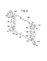
図6は、本発明の第2の実施形態に係る燃料電池スタック100を構成するエンドプレート102の斜視説明図である。なお、第1の実施形態に係る燃料電池スタック10を構成するエンドプレート20aと同一の構成要素には、同一の参照符号を付して、その詳細な説明は省略する。また、以下に説明する第3及び第4の実施形態においても同様に、その詳細な説明は省略する。
FIG. 6 is an explanatory perspective view of the
エンドプレート102の4隅には、それぞれ外方に膨出してマウント部104が一体形成される。各マウント部104は、エンドプレート102の厚さ方向を大きく設定した梁部106を一体に有している。この梁部106は、酸化剤ガス供給連通孔36a、燃料ガス排出連通孔40b、燃料ガス供給連通孔40a及び酸化剤ガス排出連通孔36bの近傍で終端する。
これにより、第2の実施形態では、マウント部104に付与される荷重を梁部106を介してエンドプレート102自体の剛性により良好に受けることができる等、上記の第1の実施形態と同様の効果が得られる。
Accordingly, in the second embodiment, the load applied to the
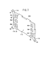
図7は、本発明の第3の実施形態に係る燃料電池スタック110を構成するエンドプレート112の斜視説明図である。
FIG. 7 is a perspective explanatory view of the
エンドプレート112には、3つの角部に対応してそれぞれ外方に突出する3つのマウント部114が一体に設けられる。マウント部114は、第1の実施形態のマウント部80と同様に構成される。
The
このように構成される第3の実施形態では、エンドプレート112には、マウント部114が3箇所に設けられるため、前記マウント部114に付与される曲げ荷重等は、前記エンドプレート112の面方向に分散される。これにより、マウント部114に付与される荷重をエンドプレート112自体の剛性によって確実に受けることができる等、上記の第1及び第2の実施形態と同様の効果が得られる。
In the third embodiment configured as described above, the
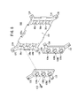
図8は、本発明の第4の実施形態に係る燃料電池スタック120を構成するエンドプレート122の要部分解斜視説明図である。
FIG. 8 is an exploded perspective view of the main part of the
エンドプレート122の各角部には、外方に突出して膨出部124が一体に設けられるとともに、各膨出部124には、孔部126が形成される。エンドプレート122の外側の面122aには、マウント部材128a、128bがボルト130を介して着脱自在に取り付けられる。
At each corner of the
マウント部材128a、128bは、エンドプレート122の面122aに取り付けられる梁部を構成するとともに、それぞれ膨出部124に対応するマウント部132が設けられる。マウント部132には、各孔部126と同軸上に孔部134が形成される。孔部134、126には、図示しない取り付けボルトが一体に挿入されることにより、燃料電池スタック120が所定の取り付け部位に固定可能である。
The
マウント部材128a、128bは、マニホールドプレート部を構成しており、酸化剤ガス供給連通孔36a、冷却媒体供給連通孔38a及び燃料ガス排出連通孔40bに連通する配管136a、136b及び136cと、燃料ガス供給連通孔40a、冷却媒体排出連通孔38b及び酸化剤ガス排出連通孔36bに連通する配管138a、138b及び138cを設ける。
The
このように構成される第4の実施形態では、上記の第1〜第3の実施形態と同様の効果が得られる他、マウント部材128a、128bをエンドプレート122とは別部材で構成することにより、前記マウント部材128a、128bを高剛性の材料で構成することが可能になる。従って、マウント部材128a、128b自体を薄肉且つ軽量化するとともに、梁部としての機能を確実に維持することができるという利点がある。
In the fourth embodiment configured as described above, the same effects as those of the first to third embodiments can be obtained, and the
10、100、110、120…燃料電池スタック
12…単位セル 14…積層体
16a、16b…ターミナルプレート
20a、20b、102、112、122…エンドプレート
24…ケーシング 30…電解質膜・電極構造体
32、34…金属セパレータ 42…固体高分子電解質膜
44…アノード側電極 46…カソード側電極
48…燃料ガス流路 50…冷却媒体流路
52…酸化剤ガス流路 60a〜60d…側板
76、84、126、134…孔部
80、104、114、132…マウント部
82、106…梁部 86…車両側取り付け部位
88…支柱部 92…取り付けボルト
124…膨出部 128a、128b…マウント部材
DESCRIPTION OF
Claims (5)
前記エンドプレートには、前記燃料電池スタックを取り付け部位に固定するためのマウント部が設けられるとともに、
前記マウント部は、該マウント部に付与される荷重を前記エンドプレートの面方向に分散可能な梁部を設けることを特徴とする燃料電池スタック。 A fuel cell stack for holding an electrolyte / electrode structure in which a pair of electrodes are provided on both sides of an electrolyte, and a laminate in which a plurality of separators are laminated, between end plates arranged at both ends in the lamination direction. ,
The end plate is provided with a mount portion for fixing the fuel cell stack to an attachment site,
The fuel cell stack, wherein the mount portion is provided with a beam portion capable of dispersing a load applied to the mount portion in a surface direction of the end plate.
前記ケーシングは、端板である前記エンドプレートと、
前記積層体の側部に配置される複数の側板と、
を備えることを特徴とする燃料電池スタック。 The fuel cell stack according to any one of claims 1 to 4, further comprising a casing that houses the stack.
The casing is the end plate that is an end plate;
A plurality of side plates disposed on the side of the laminate;
A fuel cell stack comprising:
Priority Applications (1)
| Application Number | Priority Date | Filing Date | Title |
|---|---|---|---|
| JP2006006109A JP2007188773A (en) | 2006-01-13 | 2006-01-13 | Fuel cell stack |
Applications Claiming Priority (1)
| Application Number | Priority Date | Filing Date | Title |
|---|---|---|---|
| JP2006006109A JP2007188773A (en) | 2006-01-13 | 2006-01-13 | Fuel cell stack |
Publications (1)
| Publication Number | Publication Date |
|---|---|
| JP2007188773A true JP2007188773A (en) | 2007-07-26 |
Family
ID=38343788
Family Applications (1)
| Application Number | Title | Priority Date | Filing Date |
|---|---|---|---|
| JP2006006109A Pending JP2007188773A (en) | 2006-01-13 | 2006-01-13 | Fuel cell stack |
Country Status (1)
| Country | Link |
|---|---|
| JP (1) | JP2007188773A (en) |
Cited By (8)
| Publication number | Priority date | Publication date | Assignee | Title |
|---|---|---|---|---|
| DE102008029718A1 (en) | 2008-06-23 | 2009-01-15 | Daimler Ag | Fuel cell stack for a vehicle comprises a housing having support elements for fixing the stack to the chassis of a vehicle |
| JP2010003626A (en) * | 2008-06-23 | 2010-01-07 | Honda Motor Co Ltd | Fuel cell stack |
| JP2010040500A (en) * | 2008-07-09 | 2010-02-18 | Honda Motor Co Ltd | Fuel cell stack |
| JP2010055995A (en) * | 2008-08-29 | 2010-03-11 | Honda Motor Co Ltd | Fuel cell stack and method for installing the same |
| WO2013094454A1 (en) * | 2011-12-21 | 2013-06-27 | 本田技研工業株式会社 | Fuel cell stack |
| JP2017126450A (en) * | 2016-01-13 | 2017-07-20 | 本田技研工業株式会社 | Fuel cell stack |
| WO2017183643A1 (en) * | 2016-04-20 | 2017-10-26 | 住友電気工業株式会社 | Redox flow battery transport structure, redox flow battery transport method, and redox flow battery |
| JP2020155237A (en) * | 2019-03-18 | 2020-09-24 | 本田技研工業株式会社 | Fuel cell vehicle |
-
2006
- 2006-01-13 JP JP2006006109A patent/JP2007188773A/en active Pending
Cited By (12)
| Publication number | Priority date | Publication date | Assignee | Title |
|---|---|---|---|---|
| DE102008029718A1 (en) | 2008-06-23 | 2009-01-15 | Daimler Ag | Fuel cell stack for a vehicle comprises a housing having support elements for fixing the stack to the chassis of a vehicle |
| JP2010003626A (en) * | 2008-06-23 | 2010-01-07 | Honda Motor Co Ltd | Fuel cell stack |
| JP2010040500A (en) * | 2008-07-09 | 2010-02-18 | Honda Motor Co Ltd | Fuel cell stack |
| JP2010055995A (en) * | 2008-08-29 | 2010-03-11 | Honda Motor Co Ltd | Fuel cell stack and method for installing the same |
| WO2013094454A1 (en) * | 2011-12-21 | 2013-06-27 | 本田技研工業株式会社 | Fuel cell stack |
| CN103999278A (en) * | 2011-12-21 | 2014-08-20 | 本田技研工业株式会社 | fuel cell stack |
| JPWO2013094454A1 (en) * | 2011-12-21 | 2015-04-27 | 本田技研工業株式会社 | Fuel cell stack |
| JP2017126450A (en) * | 2016-01-13 | 2017-07-20 | 本田技研工業株式会社 | Fuel cell stack |
| WO2017183643A1 (en) * | 2016-04-20 | 2017-10-26 | 住友電気工業株式会社 | Redox flow battery transport structure, redox flow battery transport method, and redox flow battery |
| CN109071107A (en) * | 2016-04-20 | 2018-12-21 | 住友电气工业株式会社 | The transportation resources of the transport structure, redox flow batteries of redox flow batteries and redox flow batteries |
| JP2020155237A (en) * | 2019-03-18 | 2020-09-24 | 本田技研工業株式会社 | Fuel cell vehicle |
| JP7103985B2 (en) | 2019-03-18 | 2022-07-20 | 本田技研工業株式会社 | Fuel cell vehicle |
Similar Documents
| Publication | Publication Date | Title |
|---|---|---|
| JP2005044688A (en) | Fuel cell stack | |
| JP4871348B2 (en) | Fuel cell stack | |
| JP4820068B2 (en) | Fuel cell stack | |
| JP4165876B2 (en) | Fuel cell stack | |
| JP4789448B2 (en) | Fuel cell stack | |
| JP4621513B2 (en) | Fuel cell stack | |
| JP4174022B2 (en) | Fuel cell stack | |
| JP2012043553A (en) | Fuel cell stack | |
| JP2007188773A (en) | Fuel cell stack | |
| JP4664030B2 (en) | Fuel cell stack | |
| JP2005116227A (en) | Fuel cell stack | |
| JP4417204B2 (en) | Fuel cell stack | |
| JP2008078071A (en) | Fuel cell stack | |
| JP4776886B2 (en) | Fuel cell stack structure | |
| JP4789478B2 (en) | Fuel cell stack and assembly method thereof | |
| JP4427419B2 (en) | Fuel cell stack | |
| JP2005251635A (en) | Fuel cell stack | |
| JP5166982B2 (en) | Fuel cell stack | |
| JP4896456B2 (en) | Fuel cell stack | |
| JP4452585B2 (en) | Fuel cell stack | |
| JP4865234B2 (en) | Fuel cell stack | |
| JP4865238B2 (en) | Fuel cell stack | |
| JP5318458B2 (en) | Fuel cell stack | |
| JP5318461B2 (en) | Fuel cell stack | |
| JP4673194B2 (en) | Fuel cell system |