JP2010003626A - Fuel cell stack - Google Patents
Fuel cell stack Download PDFInfo
- Publication number
- JP2010003626A JP2010003626A JP2008163259A JP2008163259A JP2010003626A JP 2010003626 A JP2010003626 A JP 2010003626A JP 2008163259 A JP2008163259 A JP 2008163259A JP 2008163259 A JP2008163259 A JP 2008163259A JP 2010003626 A JP2010003626 A JP 2010003626A
- Authority
- JP
- Japan
- Prior art keywords
- plate
- fuel cell
- cell stack
- end plate
- plates
- Prior art date
- Legal status (The legal status is an assumption and is not a legal conclusion. Google has not performed a legal analysis and makes no representation as to the accuracy of the status listed.)
- Granted
Links
Images


Classifications
-
- Y—GENERAL TAGGING OF NEW TECHNOLOGICAL DEVELOPMENTS; GENERAL TAGGING OF CROSS-SECTIONAL TECHNOLOGIES SPANNING OVER SEVERAL SECTIONS OF THE IPC; TECHNICAL SUBJECTS COVERED BY FORMER USPC CROSS-REFERENCE ART COLLECTIONS [XRACs] AND DIGESTS
- Y02—TECHNOLOGIES OR APPLICATIONS FOR MITIGATION OR ADAPTATION AGAINST CLIMATE CHANGE
- Y02E—REDUCTION OF GREENHOUSE GAS [GHG] EMISSIONS, RELATED TO ENERGY GENERATION, TRANSMISSION OR DISTRIBUTION
- Y02E60/00—Enabling technologies; Technologies with a potential or indirect contribution to GHG emissions mitigation
- Y02E60/30—Hydrogen technology
- Y02E60/50—Fuel cells
Abstract
Description
本発明は、一対の電極が電解質の両側に設けられた電解質・電極構造体を、セパレータにより挟持した単位セルを備え、前記単位セルが複数積層された積層体を箱状ケーシング内に収容する燃料電池スタックに関する。 The present invention includes a unit cell in which an electrolyte / electrode structure in which a pair of electrodes are provided on both sides of an electrolyte is sandwiched between separators, and a stacked body in which a plurality of the unit cells are stacked is contained in a box-shaped casing. It relates to a battery stack.
例えば、固体高分子型燃料電池は、高分子イオン交換膜からなる電解質膜(電解質)を採用している。この電解質膜の両側にアノード側電極及びカソード側電極を配設した電解質膜・電極構造体を、セパレータによって挟持することにより、燃料電池が構成されている。 For example, a polymer electrolyte fuel cell employs an electrolyte membrane (electrolyte) made of a polymer ion exchange membrane. A fuel cell is configured by sandwiching an electrolyte membrane / electrode structure in which an anode side electrode and a cathode side electrode are disposed on both sides of the electrolyte membrane with a separator.
この場合、燃料電池の発電時に、金属の表面等における電位差に起因して電流が流れ、燃料電池構成部品の一部に腐食が発生するという問題がある。そこで、例えば、特許文献1に開示されている燃料電池システムでは、セパレータに、燃料電池が複数積層されたときに積層方向に連なる流体流路が形成されているとともに、該流体流路に連通する部分には、発電時における燃料電池積層体のうち最も高電位のセパレータの電位より少なくとも一部が高い電位となっている高電位部材が設けられている。 In this case, there is a problem that during the power generation of the fuel cell, current flows due to a potential difference on the metal surface or the like, and corrosion occurs in some of the fuel cell components. Thus, for example, in the fuel cell system disclosed in Patent Document 1, a fluid channel that is continuous in the stacking direction when a plurality of fuel cells are stacked is formed in the separator, and the fluid channel communicates with the fluid channel. The portion is provided with a high potential member in which at least a part is higher than the potential of the highest potential separator in the fuel cell stack during power generation.
これにより、高電位部材からセパレータに電流が流れ、分極効果によってセパレータの電位が低くなり、腐食電流を消滅させることができ、燃料電池の構成部品(特にセパレータ)の腐食を効果的に抑制することが可能である、としている。 As a result, current flows from the high potential member to the separator, the potential of the separator is lowered by the polarization effect, the corrosion current can be eliminated, and the corrosion of the fuel cell components (particularly the separator) is effectively suppressed. Is possible.
ところで、燃料電池は、所望の発電力を得るために、所定数(例えば、数十〜数百)だけ積層した燃料電池スタックとして使用されている。この燃料電池スタックは、複数の燃料電池が積層された積層体の積層方向両端にエンドプレートが配設されるとともに、ボックス状のケーシング内に収容される場合がある。 By the way, the fuel cell is used as a fuel cell stack in which a predetermined number (for example, several tens to several hundreds) is stacked in order to obtain a desired power generation. In this fuel cell stack, end plates may be disposed at both ends in a stacking direction of a stacked body in which a plurality of fuel cells are stacked, and may be housed in a box-shaped casing.
その際、ケーシングを構成するサイドパネル(側板)は、薄板化を図るために、例えば、ステンレス鋼板(SUS材)が使用される一方、端板であるエンドプレートは、軽量化を図るために、例えば、アルミニウム板が使用されている。 At that time, for example, a stainless steel plate (SUS material) is used for the side panel (side plate) constituting the casing in order to reduce the thickness, while the end plate, which is an end plate, is used for weight reduction. For example, an aluminum plate is used.
従って、異種金属であるサイドパネルとエンドプレートとが接触することにより、電位差が発生するため、前記サイドパネルと前記エンドプレートとを連結する連結ピン(連結部材)に腐食電流が流れるという問題がある。このため、連結ピンの表面に絶縁処理を施しているが、これにより、サイドパネルとエンドプレートとの間には、電位差が存在してしまう。 Therefore, since a potential difference is generated when the side panel and the end plate, which are different metals, contact each other, there is a problem that a corrosion current flows through a connecting pin (connecting member) that connects the side panel and the end plate. . For this reason, although the insulation process is performed on the surface of the connecting pin, a potential difference exists between the side panel and the end plate.
本発明はこの種の問題を解決するものであり、簡単且つ経済的な構成で、異種金属で構成される端板と側板とを、確実に等電位に維持することが可能な燃料電池スタックを提供することを目的とする。 The present invention solves this type of problem, and provides a fuel cell stack that can reliably maintain an equipotential between an end plate and a side plate made of different metals with a simple and economical configuration. The purpose is to provide.
本発明は、一対の電極が電解質の両側に設けられた電解質・電極構造体を、セパレータにより挟持した単位セルを備え、前記単位セルが複数積層された積層体を箱状ケーシング内に収容する燃料電池スタックに関するものである。 The present invention includes a unit cell in which an electrolyte / electrode structure in which a pair of electrodes are provided on both sides of an electrolyte is sandwiched between separators, and a stacked body in which a plurality of the unit cells are stacked is contained in a box-shaped casing. It relates to a battery stack.
ケーシングは、積層体の積層方向両端部に配置される金属製の端板と、前記積層体の側部に配置されるとともに、前記端板とは異なる金属材料で形成される側板と、前記端板と前記側板とを連結するとともに、少なくとも表面が電気絶縁性を有する連結部材とを備え、前記端板と前記側板とは、導電部材を介して電気的に結合されている。 The casing is made of a metal end plate disposed at both ends in the stacking direction of the laminate, a side plate formed of a metal material different from the end plate while being disposed at the side of the laminate, and the end. The plate and the side plate are connected to each other, and at least the surface thereof is provided with a connecting member having electrical insulation, and the end plate and the side plate are electrically coupled via a conductive member.
また、少なくとも1つの側板は、互いに離間して配置される一対のプレート部材を有し、前記プレート部材同士は、導電部材を介して電気的に結合されることが好ましい。 Moreover, it is preferable that at least one side plate has a pair of plate member arrange | positioned mutually spaced apart, and the said plate members are electrically couple | bonded through a conductive member.
本発明では、端板と側板とが、導電部材を介して電気的に結合されるため、簡単且つ経済的な構成で、異種金属で構成される前記端板と前記側板とを、確実に等電位に維持することが可能になる。従って、例えば、端板が電食されて損傷することを確実に阻止することができ、燃料電池スタック全体の耐久性が良好に向上する。 In the present invention, since the end plate and the side plate are electrically coupled via the conductive member, the end plate and the side plate made of dissimilar metals can be reliably connected with a simple and economical configuration. It becomes possible to maintain the potential. Therefore, for example, it is possible to reliably prevent the end plate from being eroded and damaged, and the durability of the entire fuel cell stack is improved satisfactorily.
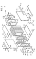
図1は、本発明の第1の実施形態に係る燃料電池スタック10の一部分解概略斜視図であり、図2は、前記燃料電池スタック10の一部断面側面図である。この燃料電池スタック10は、例えば、燃料電池車両に搭載される車載型燃料電池スタックとして使用される。
FIG. 1 is a partially exploded schematic perspective view of a
燃料電池スタック10は、複数の単位セル12が水平方向(矢印A方向)に積層された積層体14を備える。積層体14の積層方向(矢印A方向)一端には、ターミナルプレート16a、絶縁プレート18及びエンドプレート20aが外方に向かって、順次、配設される。
The
積層体14の積層方向他端には、ターミナルプレート16b、絶縁性スペーサ部材22(絶縁プレート18を用いてもよい)及びエンドプレート20bが外方に向かって、順次、配設される。燃料電池スタック10は、縦長の長方形状に構成されるエンドプレート20a、20bを端板として含む箱状のケーシング24により一体的に保持される。エンドプレート20a、20bは、例えば、アルミニウム合金やマグネシウム等を鋳造又は機械加工することにより形成される。
At the other end in the stacking direction of the stacked
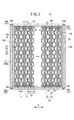
図2及び図3に示すように、各単位セル12は、電解質膜・電極構造体(電解質・電極構造体)30と、前記電解質膜・電極構造体30を挟持する薄板波形状の第1及び第2金属セパレータ32、34とを備える。なお、第1及び第2金属セパレータ32、34に代えて、カーボンセパレータを用いてもよい。
As shown in FIGS. 2 and 3, each
単位セル12の長辺方向(図3中、矢印C方向)の一端縁部(上端縁部)には、矢印A方向に互いに連通して、酸化剤ガス、例えば、酸素含有ガスを供給するための酸化剤ガス供給連通孔36a、及び燃料ガス、例えば、水素含有ガスを供給するための燃料ガス供給連通孔38aが設けられる。
In order to supply an oxidant gas, for example, an oxygen-containing gas, to one end edge (upper edge) in the long side direction (the arrow C direction in FIG. 3) of the
単位セル12の長辺方向の他端縁部(下端縁部)には、矢印A方向に互いに連通して、燃料ガスを排出するための燃料ガス排出連通孔38b、及び酸化剤ガスを排出するための酸化剤ガス排出連通孔36bが設けられる。
The other end edge (lower end edge) of the
単位セル12の短辺方向(矢印B方向)の一端縁部には、冷却媒体を供給するための冷却媒体供給連通孔40aが設けられるとともに、前記単位セル12の短辺方向の他端縁部には、前記冷却媒体を排出するための冷却媒体排出連通孔40bが設けられる。
A cooling medium
電解質膜・電極構造体30は、例えば、パーフルオロスルホン酸の薄膜に水が含浸された固体高分子電解質膜42と、前記固体高分子電解質膜42を挟持するアノード側電極44及びカソード側電極46とを備える。
The electrolyte membrane /
アノード側電極44及びカソード側電極46は、カーボンペーパ等からなるガス拡散層(図示せず)と、白金合金が表面に担持された多孔質カーボン粒子が前記ガス拡散層の表面に一様に塗布されて形成される電極触媒層(図示せず)とを有する。電極触媒層は、固体高分子電解質膜42の両面に形成される。
The
第1金属セパレータ32の電解質膜・電極構造体30に向かう面32aには、燃料ガス供給連通孔38aと燃料ガス排出連通孔38bとを連通する燃料ガス流路48が矢印C方向に沿って形成される。第1金属セパレータ32の面32bには、冷却媒体供給連通孔40aと冷却媒体排出連通孔40bとを連通する冷却媒体流路50が矢印B方向に沿って形成される。
On the
第2金属セパレータ34の電解質膜・電極構造体30に向かう面34aには、矢印C方向に沿って酸化剤ガス流路52が設けられるとともに、この酸化剤ガス流路52は、酸化剤ガス供給連通孔36aと酸化剤ガス排出連通孔36bとに連通する。第2金属セパレータ34の面34bには、第1金属セパレータ32の面32bと重なり合って冷却媒体流路50が一体的に形成される。
The
第1金属セパレータ32の面32a、32bには、この第1金属セパレータ32の外周端縁部を周回して第1シール部材54が一体成形される。第2金属セパレータ34の面34a、34bには、この第2金属セパレータ34の外周端縁部を周回して第2シール部材56が一体成形される。
A
図2に示すように、第1及び第2シール部材54、56間には、固体高分子電解質膜42の外周が、直接、ケーシング24に接触することを阻止するために、シール57が介装される。
As shown in FIG. 2, a
図1に示すように、ターミナルプレート16a、16bの中央部側には、積層方向に突出する棒状の端子部58a、58bが設けられる。端子部58a、58bは、エンドプレート20a、20bに形成された孔部59a、59bを通って外部に突出するとともに、前記端子部58a、58bには、例えば、車両走行用モータ等の負荷が接続される。
As shown in FIG. 1, rod-shaped
ケーシング24は、端板であるエンドプレート20a、20bと、積層体14の側部に配置される複数の側板60a〜60dと、前記側板60a〜60dの互いに近接する端部同士を連結するアングル部材62a〜62dと、前記エンドプレート20a、20bと前記側板60a〜60dとを連結するそれぞれ長さの異なる丸棒状の連結ピン(連結部材)64a、64bとを備える。
The
側板60a〜60dは、エンドプレート20a、20bとは異なる金属材料、例えば、ステンレス鋼板(SUS材)で形成される。側板60a〜60dは、アングル部材62a〜62d及びボルト67を介して互いに固定され、ケーシング24が構成される(図4参照)。連結ピン64a、64bは、少なくとも表面に電着塗装等による電気絶縁処理が施されている。
The
図1に示すように、エンドプレート20a、20bの上下左右各辺には、それぞれ第1支持部66a、66bが突出形成される。積層体14の矢印B方向両側に配置される側板60a、60cの長手方向(矢印A方向)両端には、第2支持部70a、70bが形成される。積層体14の上下両側に配置される側板60b、60dの長手方向両端には、第2支持部72a、72bが形成される。
As shown in FIG. 1,
図1及び図4に示すように、側板60a、60cの各第2支持部70a、70b間には、エンドプレート20a、20bの両側の各辺の第1支持部66a、66bが配置されるとともに、これらに長尺な連結ピン64aが一体的に挿入される。
As shown in FIGS. 1 and 4,
同様に、側板60b、60dの第2支持部72a、72bは、エンドプレート20a、20bの上辺及び下辺の第1支持部66a、66bと交互に配置されるとともに、これらに短尺な連結ピン64bが一体的に挿入される。
Similarly, the
図1に示すように、エンドプレート20aには、酸化剤ガス供給連通孔36aに連通する酸化剤ガス入口76a、燃料ガス供給連通孔38aに連通する燃料ガス入口78a、酸化剤ガス排出連通孔36bに連通する酸化剤ガス出口76b及び燃料ガス排出連通孔38bに連通する燃料ガス出口78bが設けられる。
As shown in FIG. 1, the
エンドプレート20bには、冷却媒体供給連通孔40aに連通する冷却媒体入口80aと、冷却媒体排出連通孔40bに連通する冷却媒体出口80bとが設けられる。
The
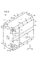
図4に示すように、燃料電池スタック10のエンドプレート20aには、加湿器82が固定される。加湿器82のハウジング84は、例えば、鋳造成形されており、エンドプレート20aに接するフランジ部86に複数のボルト88が挿入される。ボルト88がエンドプレート20aに螺合することにより、加湿器82が前記エンドプレート20aに直接固定される。
As shown in FIG. 4, a
加湿器82内には、第1及び第2加湿部90a、90bが上下に配列して収容される。第1加湿部90a及び第2加湿部90bは、空気供給配管92と加湿空気供給配管94とに接続される。第1加湿部90a及び第2加湿部90bは、例えば、中空糸膜型加湿構造を採用することができる。
In the
空気供給配管92は、図示しない空気供給用ポンプに接続されるとともに、加湿空気供給配管94は、エンドプレート20aの酸化剤ガス入口76aに接続される。
The air supply pipe 92 is connected to an unillustrated air supply pump, and the humidified
燃料電池スタック10と加湿器82とには、使用済みの生成水を含んだ酸化剤ガス(以下、オフガスという)を加湿流体として供給するためのオフガス供給配管95が接続される。オフガス供給配管95は、エンドプレート20aの酸化剤ガス出口76bに接続される。
The
エンドプレート20aと側板60aとは、導電率の高い金属材料等を用いた連結バスバー(導電部材)96を介して電気的に結合される。連結バスバー96は、エンドプレート20aにボルト98を介して固定される一端部96aを備え、この一端部96aから90゜屈曲した後、側板60aにボルト98を介して固定される他端部96bが設けられる。側板60a、連結バスバー96、エンドプレート20a、加湿器82のハウジング84及び車体フレーム100に連なる導通経路が形成される。
The
なお、エンドプレート20aと側板60aとに表面処理がなされている場合には、表面被覆を剥がすことにより、連結バスバー96と確実に電気的接触状態を保つことが好ましい。また、側板60aに代えて、側板60cとエンドプレート20aとを連結バスバー96により結合してもよい。
When surface treatment is applied to the
このように構成される燃料電池スタック10の動作について、以下に説明する。
The operation of the
先ず、図4に示すように、空気用ポンプ(図示せず)が駆動され、酸化剤ガスである外部空気が吸引されて空気供給配管92に導入される。この空気は、空気供給配管92から加湿器82内に導入され、第1及び第2加湿部90a、90bを通って加湿空気供給配管94に供給される。
First, as shown in FIG. 4, an air pump (not shown) is driven, and external air that is an oxidant gas is sucked and introduced into the air supply pipe 92. The air is introduced into the
その際、加湿器82には、後述するように、反応に使用された酸化剤ガスであるオフガスが、オフガス供給配管95から供給されている。このため、使用前の空気には、加湿器82の水透過膜(図示せず)を介してオフガス中に含まれる水分が移動し、この使用前の空気が加湿される。加湿された空気は、加湿空気供給配管94からエンドプレート20aの酸化剤ガス入口76aに供給される。
At that time, the off-gas which is the oxidant gas used for the reaction is supplied to the
一方、図1に示すように、エンドプレート20aの燃料ガス入口78aには、水素含有ガス等の燃料ガスが供給される。さらに、エンドプレート20bの冷却媒体入口80aには、純水やエチレングリコール等の冷却媒体が供給される。
On the other hand, as shown in FIG. 1, a fuel gas such as a hydrogen-containing gas is supplied to the
このため、積層体14では、矢印A方向に重ね合わされた複数の単位セル12に対し、酸化剤ガス供給連通孔36a、燃料ガス供給連通孔38a及び冷却媒体供給連通孔40aに、それぞれ酸化剤ガス、燃料ガス及び冷却媒体が矢印A方向に供給される。
Therefore, in the stacked
図3に示すように、酸化剤ガスは、酸化剤ガス供給連通孔36aから第2金属セパレータ34の酸化剤ガス流路52に導入され、電解質膜・電極構造体30のカソード側電極46に沿って移動する。一方、燃料ガスは、燃料ガス供給連通孔38aから第1金属セパレータ32の燃料ガス流路48に導入され、電解質膜・電極構造体30のアノード側電極44に沿って移動する。
As shown in FIG. 3, the oxidant gas is introduced into the oxidant
従って、各電解質膜・電極構造体30では、カソード側電極46に供給される酸化剤ガスと、アノード側電極44に供給される燃料ガスとが、電極触媒層内で電気化学反応により消費され、発電が行われる。
Therefore, in each electrolyte membrane /
次いで、カソード側電極46に供給されて消費された酸化剤ガスは、酸化剤ガス排出連通孔36bに沿って流動した後、オフガスとしてエンドプレート20aからオフガス供給配管95に排出される(図4参照)。同様に、アノード側電極44に供給されて消費された燃料ガスは、燃料ガス排出連通孔38bに排出されて流動し、エンドプレート20aの燃料ガス出口78bから燃料ガス循環供給系(図示せず)に排出される。
Next, the oxidant gas consumed by being supplied to the
また、冷却媒体は、冷却媒体供給連通孔40aから第1及び第2金属セパレータ32、34間の冷却媒体流路50に導入され、矢印B方向に沿って流動する。この冷却媒体は、電解質膜・電極構造体30を冷却した後、冷却媒体排出連通孔40bを移動してエンドプレート20bの冷却媒体出口80bから排出される(図1参照)。
The cooling medium is introduced into the cooling
この場合、第1の実施形態では、図4に示すように、エンドプレート20aと側板60aとは、連結バスバー96を介して電気的に結合されている。そして、側板60a、連結バスバー96、エンドプレート20a、加湿器82のハウジング84及び車体フレーム100に連なる導通経路が形成されている。このため、燃料電池スタック10の発電時に、異種金属であるエンドプレート20aと側板60aとが接触することにより電位差が発生することを、良好に阻止することができる。
In this case, in the first embodiment, as shown in FIG. 4, the
これにより、簡単且つ経済的な構成で、エンドプレート20aと側板60aとを、確実に等電位に維持することが可能になる。従って、例えば、側板60aが電食されて損傷することを確実に阻止することができ、燃料電池スタック10全体の耐久性が良好に向上するという効果が得られる。
This makes it possible to reliably maintain the
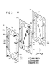
図5は、本発明の第2の実施形態に係る燃料電池スタック110の斜視説明図である。なお、第1の実施形態に係る燃料電池スタック10と同一の構成要素には同一の参照符号を付して、その詳細な説明は省略する。
FIG. 5 is a perspective explanatory view of a
燃料電池スタック110を構成するケーシング112は、少なくとも側板60a又は側板60cに代えて側板114を備える。側板114は、上下(矢印C方向)に2分割されて互いに距離hだけ離間して配置される一対のプレート部114a、114bを有する。プレート部114a、114b間には、各単位セル12毎に、あるいは複数の単位セル12毎(例えば、2つの単位セル12毎)に設けられるセル電圧端子(図示せず)に接続されるコネクタ116が配置される。
The
プレート部114a、114bは、例えば、ステンレス鋼板で形成され、エンドプレート20aと前記プレート部114aとは、連結バスバー(導電部材)96を介して電気的に結合される。プレート部114a、114b間は、連結バスバー118を介して電気的に結合される。この連結バスバー118の両端は、例えば、ボルト67を介してプレート部114a、114bに連結される。
The
このように構成される第2の実施形態では、互いに距離hだけ離端して配置される一対のプレート部114a、114bが、連結バスバー118を介して電気的に結合されている。このため、プレート部114a、114b間に電位差が発生することがなく、しかも側板114とエンドプレート20aとを、確実に等電位に維持することが可能になる。これにより、上記の第1の実施形態と同様の効果が得られる。
In the second embodiment configured as described above, the pair of
図6は、本発明の第3の実施形態に係る燃料電池スタック120の斜視説明図である。なお、第2の実施形態に係る燃料電池スタック110と同一の構成要素には同一の参照符号を付して、その詳細な説明は省略する。
FIG. 6 is a perspective explanatory view of a
側板114を構成するプレート部114a、114b間は、アースケーブル122を介して電気的に結合される。アースケーブル122の両端は、ボルト67を介してプレート部114a、114bに連結されるとともに、固定部材124を介して前記プレート部114a、114bに保持される。
The
このように構成される第3の実施形態では、上記の第2の実施形態と同様の効果が得られる。 In the third embodiment configured as described above, the same effect as in the second embodiment can be obtained.
10、110、120…燃料電池スタック
12…単位セル 14…積層体
16a、16b…ターミナルプレート 18…絶縁プレート
20a、20b…エンドプレート 22…スペーサ部材
24、112…ケーシング 30…電解質膜・電極構造体
32、34…金属セパレータ 42…固体高分子電解質膜
44…アノード側電極 46…カソード側電極
48…燃料ガス流路 50…冷却媒体流路
52…酸化剤ガス流路 60a〜60d、114…側板
64a、64b…連結ピン 82…加湿器
96、118…連結バスバー 114a、114b…プレート部
122…アースケーブル
DESCRIPTION OF
Claims (2)
前記ケーシングは、前記積層体の積層方向両端部に配置される金属製の端板と、
前記積層体の側部に配置されるとともに、前記端板とは異なる金属材料で形成される側板と、
前記端板と前記側板とを連結するとともに、少なくとも表面が電気絶縁性を有する連結部材と、
を備え、
前記端板と前記側板とは、導電部材を介して電気的に結合されることを特徴とする燃料電池スタック。 A fuel cell stack comprising a unit cell in which an electrolyte / electrode structure having a pair of electrodes provided on both sides of an electrolyte is sandwiched between separators, and a stacked body in which a plurality of the unit cells are stacked is housed in a box-shaped casing. And
The casing is made of metal end plates disposed at both ends in the stacking direction of the laminate,
A side plate that is disposed on a side of the laminate and formed of a metal material different from the end plate;
A connecting member that connects the end plate and the side plate, and at least a surface having electrical insulation,
With
The end plate and the side plate are electrically coupled via a conductive member.
前記プレート部材同士は、導電部材を介して電気的に結合されることを特徴とする燃料電池スタック。 2. The fuel cell stack according to claim 1, wherein at least one of the side plates includes a pair of plate members that are spaced apart from each other.
The fuel cell stack, wherein the plate members are electrically coupled to each other through a conductive member.
Priority Applications (1)
| Application Number | Priority Date | Filing Date | Title |
|---|---|---|---|
| JP2008163259A JP5207847B2 (en) | 2008-06-23 | 2008-06-23 | Fuel cell stack |
Applications Claiming Priority (1)
| Application Number | Priority Date | Filing Date | Title |
|---|---|---|---|
| JP2008163259A JP5207847B2 (en) | 2008-06-23 | 2008-06-23 | Fuel cell stack |
Publications (2)
| Publication Number | Publication Date |
|---|---|
| JP2010003626A true JP2010003626A (en) | 2010-01-07 |
| JP5207847B2 JP5207847B2 (en) | 2013-06-12 |
Family
ID=41585172
Family Applications (1)
| Application Number | Title | Priority Date | Filing Date |
|---|---|---|---|
| JP2008163259A Active JP5207847B2 (en) | 2008-06-23 | 2008-06-23 | Fuel cell stack |
Country Status (1)
| Country | Link |
|---|---|
| JP (1) | JP5207847B2 (en) |
Cited By (3)
| Publication number | Priority date | Publication date | Assignee | Title |
|---|---|---|---|---|
| FR3023561A1 (en) * | 2014-07-10 | 2016-01-15 | Brgm | PROCESS FOR RECYCLING LUMINESCENT POWDERS |
| CN111082088A (en) * | 2018-10-22 | 2020-04-28 | 本田技研工业株式会社 | Fuel cell stack |
| GB202013308D0 (en) | 2020-08-26 | 2020-10-07 | Daimler Ag | Fuel cell unit with end plate for combined use as part of a housing and electric power conduction means |
Citations (3)
| Publication number | Priority date | Publication date | Assignee | Title |
|---|---|---|---|---|
| JP2006228511A (en) * | 2005-02-16 | 2006-08-31 | Honda Motor Co Ltd | Fuel cell stack |
| JP2006331805A (en) * | 2005-05-25 | 2006-12-07 | Honda Motor Co Ltd | Stack structure of fuel cell |
| JP2007188773A (en) * | 2006-01-13 | 2007-07-26 | Honda Motor Co Ltd | Fuel cell stack |
-
2008
- 2008-06-23 JP JP2008163259A patent/JP5207847B2/en active Active
Patent Citations (3)
| Publication number | Priority date | Publication date | Assignee | Title |
|---|---|---|---|---|
| JP2006228511A (en) * | 2005-02-16 | 2006-08-31 | Honda Motor Co Ltd | Fuel cell stack |
| JP2006331805A (en) * | 2005-05-25 | 2006-12-07 | Honda Motor Co Ltd | Stack structure of fuel cell |
| JP2007188773A (en) * | 2006-01-13 | 2007-07-26 | Honda Motor Co Ltd | Fuel cell stack |
Cited By (5)
| Publication number | Priority date | Publication date | Assignee | Title |
|---|---|---|---|---|
| FR3023561A1 (en) * | 2014-07-10 | 2016-01-15 | Brgm | PROCESS FOR RECYCLING LUMINESCENT POWDERS |
| CN111082088A (en) * | 2018-10-22 | 2020-04-28 | 本田技研工业株式会社 | Fuel cell stack |
| GB202013308D0 (en) | 2020-08-26 | 2020-10-07 | Daimler Ag | Fuel cell unit with end plate for combined use as part of a housing and electric power conduction means |
| WO2022043342A1 (en) | 2020-08-26 | 2022-03-03 | Cellcentric Gmbh & Co. Kg | Fuel cell unit with end plate for combined use as part of a housing and electric power conduction means |
| DE102021121913A1 (en) | 2020-08-26 | 2022-03-03 | Cellcentric Gmbh & Co. Kg | FUEL CELL ASSEMBLY WITH END PLATE FOR COMBINED USE AS PART OF A HOUSING AND CONDUCTING MEANS FOR ELECTRICAL POWER |
Also Published As
| Publication number | Publication date |
|---|---|
| JP5207847B2 (en) | 2013-06-12 |
Similar Documents
| Publication | Publication Date | Title |
|---|---|---|
| JP4630529B2 (en) | Fuel cell system | |
| JP4505204B2 (en) | Fuel cell system | |
| US8003278B2 (en) | Fuel cell | |
| JP4820068B2 (en) | Fuel cell stack | |
| JP4165876B2 (en) | Fuel cell stack | |
| JP6180331B2 (en) | Fuel cell stack | |
| JP2007188773A (en) | Fuel cell stack | |
| JP4672989B2 (en) | Fuel cell stack | |
| JP4174022B2 (en) | Fuel cell stack | |
| JP5207847B2 (en) | Fuel cell stack | |
| JP4896456B2 (en) | Fuel cell stack | |
| JP2004152684A (en) | Fuel cell stack | |
| JP5574894B2 (en) | Fuel cell stack | |
| JP2017111998A (en) | Fuel cell | |
| JP2006100075A (en) | Fuel cell stack | |
| JP4773055B2 (en) | FUEL CELL STACK, SEPARATOR INTERMEDIATE AND SEPARATOR MANUFACTURING METHOD | |
| JP2015009768A (en) | Mounting structure for fuel cell stack | |
| JP2006216333A (en) | Fuel cell stack | |
| JP4494830B2 (en) | Fuel cell stack | |
| JP2014143070A (en) | Fuel cell stack | |
| JP2005243286A (en) | Fuel cell stack | |
| JP4214022B2 (en) | Fuel cell stack | |
| JP2007234315A (en) | Fuel cell | |
| JP2006216247A (en) | Fuel cell stack | |
| JP5318458B2 (en) | Fuel cell stack |
Legal Events
| Date | Code | Title | Description |
|---|---|---|---|
| A621 | Written request for application examination |
Free format text: JAPANESE INTERMEDIATE CODE: A621 Effective date: 20101125 |
|
| TRDD | Decision of grant or rejection written | ||
| A01 | Written decision to grant a patent or to grant a registration (utility model) |
Free format text: JAPANESE INTERMEDIATE CODE: A01 Effective date: 20130122 |
|
| A61 | First payment of annual fees (during grant procedure) |
Free format text: JAPANESE INTERMEDIATE CODE: A61 Effective date: 20130219 |
|
| FPAY | Renewal fee payment (event date is renewal date of database) |
Free format text: PAYMENT UNTIL: 20160301 Year of fee payment: 3 |
|
| R150 | Certificate of patent or registration of utility model |
Ref document number: 5207847 Country of ref document: JP Free format text: JAPANESE INTERMEDIATE CODE: R150 Free format text: JAPANESE INTERMEDIATE CODE: R150 |