JP2007185672A - Apparatus for bending shapes - Google Patents
Apparatus for bending shapes Download PDFInfo
- Publication number
- JP2007185672A JP2007185672A JP2006004397A JP2006004397A JP2007185672A JP 2007185672 A JP2007185672 A JP 2007185672A JP 2006004397 A JP2006004397 A JP 2006004397A JP 2006004397 A JP2006004397 A JP 2006004397A JP 2007185672 A JP2007185672 A JP 2007185672A
- Authority
- JP
- Japan
- Prior art keywords
- bending
- bent
- pressing
- web
- support structure
- Prior art date
- Legal status (The legal status is an assumption and is not a legal conclusion. Google has not performed a legal analysis and makes no representation as to the accuracy of the status listed.)
- Pending
Links
Images


Abstract
Description
本発明はH形鋼のような形鋼に曲げ加工を行えるようにする形鋼の曲げ加工装置に関するものである。 The present invention relates to an apparatus for bending a shaped steel that enables bending of a shaped steel such as an H-shaped steel.
形鋼は部材としての強度が大きいため、各種建造物の建材として広く使用されてきている。 Since shape steel has high strength as a member, it has been widely used as a building material for various buildings.
この種の形鋼は、その用途に応じて直線状のまま使用したり、所要の曲率に曲げて用いる場合がある。 Depending on the application, this type of shape steel may be used in a straight line or may be bent to a required curvature.
たとえば、液化天然ガス(LNG)の貯蔵用のタンクの屋根は、外側へ膨らむ緩やかな曲面となるようにしてあり、かかるLNGタンクの屋根の骨材として用いられる形鋼、特にH形鋼は、緩やかな曲面に曲げ加工されたものが用いられている。 For example, the roof of a tank for storage of liquefied natural gas (LNG) has a gentle curved surface that swells outward, and the shape steel used as the aggregate of the roof of such an LNG tank, particularly the H-section steel, A material that has been bent into a gently curved surface is used.
このような曲面形状を有する構造物に用いられるH形鋼としては、予め必要な曲面に形成されたウエブに、同じ曲率に曲げて形成されたフランジの中央部を当接させて溶接してビルトアップしたものが用いられるか、真直ぐのウエブと真直ぐのフランジを組立ててなるH形鋼を曲げ加工したものが用いられる。 As the H-section steel used for such a curved structure, a built-in flange is formed by abutting the center portion of a flange formed by bending to the same curvature on a previously formed curved surface. An up-stretched one is used, or one obtained by bending an H-shaped steel obtained by assembling a straight web and a straight flange is used.
後者のH形鋼を製作した後に所要の曲率半径に曲げ加工するものとしては、近年、図6に示すようなものが提案されている。 In recent years, as shown in FIG. 6, there has been proposed a method of bending the latter H-shaped steel to a required radius of curvature after manufacturing.
すなわち、H形鋼aを一方のフランジが外径側、他方のフランジが内径側となるように曲げようとする場合の外径側に一対の固定ローラーbとcを配設すると共に、これら両固定ローラーbとcの中間付近のH形鋼aの内径側に、H形鋼aに押圧力を加えるためのプレスローラーdを配設して、該プレスローラーdでH形鋼aの内径側を押圧させることにより、2つの固定ローラーb,cで支えられているH形鋼aに曲げを与えるようにする。更に、上記2つの固定ローラーbとcの中間付近における外径側のフランジeの内側と外側にローラー(ピンチローラー)f,gを配置してフランジeを内外側から押えるようにし、且つ該ローラーf,gを外径側へ移動できるようにして、プレスローラーdでH形鋼aを押し曲げるときにローラーf,gを、プレスローラーdの押圧力が作用する方向(外径方向)へ移動させて、外径側のフランジeを外径側へ引張るようにしてある。これにより、プレスローラーdで押圧されてH形鋼aが曲げ加工されるとき、押圧荷重が作用しているウエブhを引張ることにより、ウエブhの押圧荷重を低減し、座屈を防止するようにしてある(たとえば、特許文献1参照)。 That is, a pair of fixed rollers b and c are disposed on the outer diameter side when the H-shaped steel a is bent so that one flange is on the outer diameter side and the other flange is on the inner diameter side. A press roller d for applying a pressing force to the H-section steel a is disposed on the inner diameter side of the H-section steel a near the middle of the fixed rollers b and c, and the inner diameter side of the H-section steel a is pressed by the press roller d. Is pressed to bend the H-shaped steel a supported by the two fixed rollers b and c. Further, rollers (pinch rollers) f and g are arranged inside and outside the flange e on the outer diameter side in the vicinity of the middle between the two fixed rollers b and c so as to press the flange e from the inside and outside, and the roller F and g can be moved to the outer diameter side, and when pressing the H-section steel a with the press roller d, the rollers f and g are moved in the direction in which the pressing force of the press roller d acts (outer diameter direction). Thus, the outer diameter side flange e is pulled toward the outer diameter side. As a result, when the H-shaped steel a is bent by being pressed by the press roller d, the pressing load of the web h is reduced by pulling the web h on which the pressing load is applied, so that buckling is prevented. (For example, refer to Patent Document 1).
ところが、特許文献1に記載されているように、H形鋼を一方のフランジが外径側、他方のフランジが内径側となるように曲げ加工する場合に、プレスローラーdで押圧してH形鋼aを曲げるときに、外径側のフランジeをピンチローラーで引張って強制変位を与えるようにすると、ウエブhの座屈は防止することは可能と考えられるが、ウエブhとフランジとの溶接部が破断するおそれがある。すなわち、H形鋼のウエブとフランジの素材を9%Ni鋼として、ウエブとフランジを70%Ni鋼を溶材として溶接してなるH形鋼の場合は、溶材の方の引張り強度が弱いので、特許文献1に記載されているようなウエブの座屈防止策として、曲げられるH形鋼の外径側のフランジを外側へ引張ることにより強制変位を与えるようにすると、ウエブとフランジの溶接部が破断してしまうという問題がある。又、ウエブ自体が破断してしまうということもある。
However, as described in
そこで、本発明は、H形鋼をウエブの幅方向に曲げ加工するときにウエブに作用する押圧荷重を分散させて、ウエブが座屈しないようにすると共にフランジの溶接部が破断することなく曲げ加工できるようにし、更に、ウエブの座屈防止に用いるものを曲げ加工後に容易に取り外すことができるようにする形鋼の曲げ加工装置を提供しようとするものである。 Therefore, the present invention distributes the pressing load acting on the web when bending the H-shaped steel in the width direction of the web so that the web does not buckle and bends without breaking the welded portion of the flange. It is another object of the present invention to provide a bending apparatus for shaped steel that can be machined and that can be easily removed after bending for use in preventing buckling of the web.
本発明は、上記課題を解決するために、曲げ加工しようとするH形鋼を一方のフランジが外径側、他方のフランジが内径側となるように曲げるようにする押圧装置と、上記H形鋼の曲げ加工する位置のウエブを挟むようにフランジ間に介在させるようにする伸縮式とした支持構造物とを備えてなる構成とする。 In order to solve the above-described problems, the present invention provides a pressing device that bends an H-shaped steel to be bent so that one flange is on the outer diameter side and the other flange is on the inner diameter side, and the H-shaped steel. It is configured to include a telescopic support structure that is interposed between flanges so as to sandwich a web at a position where steel is bent.
又、上記構成における伸縮式とした支持構造物を、回転体とねじにより伸縮できる単数又は複数の棒状物としたり、又は、油圧伸縮部材として、H形鋼を曲げ加工したときの曲面に合わせてある凸面と凹面を有する支持体を両端に備えたものとする。 In addition, the support structure in the above-described configuration is made into a single or a plurality of rods that can be expanded and contracted by a rotating body and screws, or as a hydraulic expansion / contraction member, according to a curved surface when H-shaped steel is bent. A support having a certain convex surface and a concave surface is provided at both ends.
更に、上記支持構造物を、中央部の油圧伸縮部材の両端部に押えローラーを取り付けると共に、H形鋼が押圧力を受けるところに位置させる押えローラーをリンク部材又は油圧伸縮部材を介して上記中央部の油圧伸縮部材側に連結させてなるものとしてもよい。 Furthermore, the support structure is attached to both ends of the central hydraulic expansion / contraction member with a press roller, and the press roller for positioning the H-shaped steel at the place where the pressing force is received is provided via the link member or the hydraulic expansion / contraction member. It is good also as what is connected with the hydraulic expansion-contraction member side of a part.
本発明の形鋼の曲げ加工装置によれば、次のような優れた効果が奏し得られる。
(1)曲げ加工しようとするH形鋼を一方のフランジが外径側、他方のフランジが内径側となるように曲げるようにする押圧装置と、上記H形鋼の曲げ加工する位置のウエブを挟むようにフランジ間に介在させるようにする伸縮式とした支持構造物とを備えてなる構成としてあるので、押圧装置で形鋼を曲げるときに該押圧装置による押圧荷重を支持構造物により分散させることができて、ウエブに作用する荷重を座屈荷重以下にすることができ、従来のローラーによる引張りを必要とすることなくウエブの座屈と破断を防止することができて、従来のローラーを不要にできる。又、支持構造物が伸縮式としてあるので、H形鋼のフランジ間への介装時や取外しが容易である。
(2)伸縮式とした支持構造物を、棒状物として、内径側となるように押圧力を加えるところに内外径の方向へ向けて用いることにより押圧装置による押圧荷重をより確実に分散させることができ、ウエブの座屈防止と破断防止が図れる。
(3)伸縮式とした支持構造物を油圧伸縮部材として、両端に、H形鋼を曲げ加工したときの曲面に合わせてある凸面と凹面を有する支持体を取り付けて用いることにより、押圧荷重をより有効に分散させることができる。
(4)支持構造物として、複数の押えローラーを用いる構成とすることにより、幅広く押圧荷重を分散させることができる。
According to the bending apparatus for shape steel of the present invention, the following excellent effects can be obtained.
(1) A pressing device that bends the H-shaped steel to be bent so that one flange is on the outer diameter side and the other flange is on the inner diameter side, and a web at a position where the H-shaped steel is bent. Since it is configured to include a telescopic support structure that is interposed between the flanges so as to be sandwiched, the pressing load by the pressing device is dispersed by the supporting structure when the shape steel is bent by the pressing device. The load acting on the web can be reduced below the buckling load, and the web can be prevented from buckling and breaking without the need for tension by the conventional roller. It can be made unnecessary. Moreover, since the support structure is of a telescopic type, it can be easily inserted or removed between the flanges of the H-section steel.
(2) Dispersing the pressing load by the pressing device more reliably by using the support structure made of a telescopic type as a rod-shaped object and applying the pressing force toward the inner diameter side in the direction of the inner and outer diameters. This prevents web buckling and breakage.
(3) By using a support structure having a telescopic structure as a hydraulic telescopic member, attaching a support body having a convex surface and a concave surface matched to a curved surface when H-shaped steel is bent at both ends, and using a pressing load. It can be more effectively dispersed.
(4) By adopting a configuration using a plurality of press rollers as the support structure, it is possible to widely disperse the pressing load.
以下、本発明を実施するための最良の形態を図面を参照して説明する。 The best mode for carrying out the present invention will be described below with reference to the drawings.
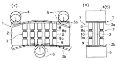
図1(イ)(ロ)は本発明の実施の一形態を示すもので、たとえば、LNGタンクの屋根骨材として用いられるように、長尺のウエブ2と長尺の2枚のフランジ3a,3bとを溶接して組み立ててなる真直ぐのH形鋼1を、本発明の装置により順次長手方向に曲げ加工しながら移動して、全長に亘り所要の曲率半径を有する円弧形状とするようにする。
FIGS. 1A and 1B show an embodiment of the present invention. For example, as used as a roof aggregate of an LNG tank, a
なお、図面はいずれも説明の便宜上、H形鋼1としては、1個所で曲げ加工するときの長さとして示してある。
In the drawings, for convenience of explanation, the H-
又、曲げ加工しようとするH形鋼1の曲げ方向は、ウエブ2に対して垂直となる方向であり、フランジ3a,3bが上下に位置するような姿勢にH形鋼1を横長にして置き、上下方向に曲げ変形を与えるようにする場合として示してある。
Also, the bending direction of the H-
図1(イ)(ロ)に示す本発明の形鋼の曲げ加工装置は、H形鋼1を曲げ加工するときに用いる押圧装置としての2本の押しローラー4,5及び1本の押しローラー6と、H形鋼1に曲げ加工を施す位置のフランジ3a,3b間にウエブ2に沿うようにして配置して用いる伸縮式の棒状の支持構造物、たとえば、ターンバックル方式で伸縮する支持構造物7とを備えたものとする。
1 (a) and 1 (b), the shape steel bending apparatus of the present invention includes two
上記ターンバックル方式で伸縮する支持構造物7は、右ねじ8aと左ねじ9aを有するロッド8,9と、該ロッド8,9の各ねじ8a,9aに螺合させた回転体10とからなり、回転体10をロッド8,9に対して右方向又は左方向へ回転させることにより長さを調節できるようにしてある。
The
又、上記H形鋼1を曲げ加工しようとする個所の曲げ方向の外径側となる上側に配設される2本の押しローラー4,5は、所要の間隔、すなわち、1回の曲げ変形を与える領域に合わせた間隔で配置されて、上下方向へ移動させられて押付力を付与したり、押付力を解除できるように図示しない駆動装置に支持された構成としてある。又、上記H形鋼1の曲げ方向の内径側となる下側に配設される1本の押しローラー6は、上記2本の押しローラー4,5の中間位置に配置されて、上記2本の押しローラー4,5と同様に、上下方向へ移動させられて押圧力を付与したり、押圧力を解除できるように図示しない駆動装置に支持された構成としてある。
In addition, the two
上記構成としてあるので、H形鋼1を曲げ加工しようとするときは、長尺のH形鋼1の曲げ加工しようとする個所に、押圧装置としての外径側の2本の押しローラー4,5と内径側の1本の押しローラー6をセットし、横方向に置かれているH形鋼1の図上上側にあるフランジ3aの外面と下側にあるフランジ3bの下面に接するようにする。
Since it is configured as described above, when bending the H-
この状態で、複数本の伸縮式の支持構造物7を立ててH形鋼1の長手方向に並べ、ウエブ2を挟んで両側のフランジ3a,3b間に図示の如く配置する。このとき、各支持構造物7は、回転体10を適宜回転させて高さ(長さ)を調整して、フランジ3a,3b間に挟持させて取り付けておくようにする。
In this state, a plurality of
この状態で押しローラー4,5と6を押圧方向に駆動させ、それぞれのローラー4,5,6を実線で示す位置から二点鎖線で示す位置に移動させてH形鋼1に押圧力を加えるようにする。これによりH形鋼1は、外径側の2本の押しローラー4,5による2点の押圧と、内径側にある1本の押しローラー6による1点の押圧によって、実線で示す直線の状態から二点鎖線で示す状態に曲げ変形させられる。
In this state, the
上記外径側の2本のローラー4,5と内径側の1本のローラー6によるH形鋼1の曲げ動作を行うとき、ウエブ2には押圧荷重が作用してウエブ2が座屈することになるため、従来では、外径側となるフランジ3aを外側へ引張るようにしていたが、本発明では、図示の如く伸縮式の支持構造物7を複数並べて立てて上下のフランジ3a,3b間に配置した状態でH形鋼1を押しローラー4,5,6にて曲げるようにする。そのため、H形鋼1の曲げ加工される部分では、フランジ3aと3bの間に伸縮式としてある支持構造物7が介在させてあるので、H形鋼1を内径側の押しローラー6により曲げるとき、複数の支持構造物7が外径側となるフランジ3aに接したまま押されることになり、H形鋼1が曲げられるときに作用する押圧荷重を上記支持構造物7により分散させることができることになる。これにより、ウエブ2に生じる荷重を座屈荷重以下にすることができて、ウエブ2を座屈しないようにすることができる。この際、外径側のフランジ3aを外方へ押したり引張るようなことがないので、フランジ3aとウエブ2との溶接部が破断したり、ウエブ2が破断するようなこともない。
When the H-
上記のようにしてH形鋼1の曲げ加工が終了すると、上記各伸縮式とした支持構造物7を、回転体10を回して短縮させ、フランジ3a,3b間より取り外すようにする。
When the bending process of the H-
上記のようにしてH形鋼1の一部分の曲げ加工が終ると、次の曲げ加工位置へ押圧装置としての押しローラー4,5,6を移動させてセットさせるようにする。この場合、H形鋼1を移動させることができる状態であれば、ローラー4,5,6に対してH形鋼1を移動させて曲げ加工位置に合わせるようにする。
When the bending of a part of the H-
H形鋼1の次の曲げ加工位置では、前記と同様に、フランジ3a,3b間に、伸縮式としてある支持構造物7を並べて立てて配置し、各々長さ調整してフランジ3a,3b間に挟持させて取り付けるようにする。
At the next bending position of the H-
以後、順次、上記操作を繰り返して、長尺のH形鋼1の全長に亘り必要な曲率半径となる曲げを与えるようにする。
Thereafter, the above operations are sequentially repeated so as to give a bending having a required radius of curvature over the entire length of the long H-
なお、上記実施の形態では、複数の伸縮式の支持構造物7をそれぞれ1本1本並べてフランジ3a,3b間に取り付けるようにしたが、複数本の支持構造物7を一列状に数珠つなぎにしてもよい。このようにすれば、取り扱いが楽で且つ紛失のおそれがなくて有利である。
In the above embodiment, each of the plurality of
次に、図2(イ)(ロ)は本発明の実施の他の形態を示すもので、図1(イ)(ロ)に示す実施の形態の場合と同様に、H形鋼1を外径側の押しローラー4,5と内径側の押しローラー6により曲げ加工するようにしてある構成において、複数の伸縮式とした支持構造物7をフランジ3aと3b間に介在させてH形鋼1の曲げ時にウエブ2が座屈するのを防止するようにした構成に代えて、伸縮式とし且つ両端に支持体を取り付けた支持構造物11を用いるようにしたものである。
Next, FIGS. 2 (a) and 2 (b) show another embodiment of the present invention. Similarly to the embodiment shown in FIGS. 1 (a) and 1 (b), the H-
すなわち、油圧伸縮部材としての油圧シリンダ又はジャッキ12のロッド13の先端に、H形鋼1を曲げ加工する曲率に合わせた曲面に湾曲させて予め成形してなる所要大きさの湾曲させた支持体14を取り付けると共に、油圧シリンダ又はジャッキ12のヘッド側端部に、同様に湾曲させて成形した所要大きさの湾曲させた支持体15を取り付けて、全体の長さを調整できるようにした支持構造物11を構成する。
That is, a curved support body of a required size formed by bending a curved surface in accordance with a curvature for bending the H-
図2(イ)(ロ)では、ロッド13の先端側を、H形鋼1を曲げるときの外径側に向けるようにするために、湾曲させた支持体14を凸面部が外側となるようロッド13に取り付けてあり、湾曲させた支持体15は凹面部が外側となるように油圧シリンダ又はジャッキ12に取り付けてある。
2 (a) and 2 (b), in order that the tip side of the
上記構成としてある支持構造物11を、ウエブ2を挟んで1本ずつ用いるように用意し、図2(イ)に示す如く、内径側の押しローラー6の位置における上下フランジ3a,3b間に立てて配置し、伸長作動させて、上下の支持体14と15をフランジ3aと3bの内面に接触させて保持させておくようにする。次いで、外径側の押しローラー4,5と内径側の押しローラー6を作動させてH形鋼1に曲げ変形を与えるようにする。
The
この実施の形態によっても、上記H形鋼1に曲げ荷重がかけられてH形鋼1が曲げられる際、内径側の押しローラー6で押されるところのH形鋼1のフランジ3a,3b間には油圧式の支持構造物11が介在させてあるので、前記の実施の形態の場合と同様に、H形鋼1を内径側の押しローラー6により曲げるとき、支持構造物11に外径側となるフランジ3aが接したまま押されることになる。これにより、H形鋼1が曲げられるときに作用する押圧荷重を上記支持構造物11により分散させることができて、ウエブ2に生じる荷重を座屈荷重以下にすることができ、ウエブ2を座屈しないようにすることができる。
Also in this embodiment, when a bending load is applied to the H-
又、この実施の形態では、曲げられたH形鋼1の外径側のフランジ3aは、支持構造物11の上端部の支持体14の凸状とした外表面に沿わされることになり、一方、曲げられたH形鋼1の内径側のフランジ3bは、支持構造物11の下端部の支持体15の凹状とした外表面に沿わされることになるようにしてあるので、H形鋼1が曲げられるときの押圧荷重を支持構造物11でより有効に分散させることができる。
Further, in this embodiment, the
上記のようにして所定個所でのH形鋼1の曲げ加工が終ると、支持構造物11を短縮してフランジ3a,3b間より取り外し、次の曲げ加工位置へ移すようにする。
When the bending of the H-
図3は図2(イ)(ロ)の変形例を示すもので、図2(イ)(ロ)では、油圧シリンダ又はジャッキ12のロッド13の先端と油圧シリンダ又はジャッキ12のヘッド側端部に、湾曲させた支持体14,15を固定した場合を示したが、これに代えて、湾曲させた支持体14と15をロッド13と油圧シリンダ又はジャッキ12にそれぞれピン16により取り外し可能に取り付けるようにしたものであり、その他の構成は図2(イ)(ロ)に示したものと同じであり、同一のものには同一の符号が付してある。
FIG. 3 shows a modification of FIG. 2 (a) (b). In FIG. 2 (b) (b), the tip of the
この例によれば、湾曲した支持体14,15が損傷した場合に交換することができるという利点があるほか、前記した図2(イ)(ロ)に示す実施の形態と同様の作用効果を有する。
According to this example, there is an advantage that the
又、図4(イ)(ロ)は本発明の実施の更に他の形態を示すもので、図1(イ)(ロ)や図2(イ)(ロ)の実施の形態と同様に、H形鋼1を外径側に配した2本の押しローラー4,5と、内径側に配した1本の押しローラー6で曲げるようにして、曲げるときに曲げる位置のウエブ2を挟むように支持構造物7や11を配置するようにしてある構成において、上記支持構造物11の変形例を示すものである。
4 (a) and (b) show still another embodiment of the present invention. Similar to the embodiments of FIGS. 1 (a) and (b) and FIGS. 2 (a) and (b), The H-shaped
すなわち、油圧伸縮部材としての油圧シリンダ又はジャッキ12のロッド13の先端に押えローラー17を取り付けると共に、油圧シリンダ又はジャッキ12のヘッド側端部に押えローラー18を取り付ける。又、上記油圧シリンダ又はジャッキ12のヘッド側の押えローラー18の軸に一端を回動可能に取り付けたリンク部材19aと19bの各先端部に、押えローラー20と21をそれぞれ取り付け、該押えローラー20と21の軸に一端(外端)を回動可能に取り付けたリンク部材22aと22bの他端側(内端側)を、上記油圧シリンダ又はジャッキ12のロッド13に軸心方向に長孔を設けてピンで枢着するか、又は図示の如く上記ロッド13の軸心方向にスライドできる筒体23を設けて、該筒体23にピンでそれぞれ上下方向に回動可能に枢着して、上記中央部の押えローラー18と両端の押えローラー20,21との相対変位時に、リンク部材22aと22bの内端側がロッド13に沿って該ロッド13の軸心方向へ変位できるようにした構成の支持構造物24としたものである。
That is, the
H形鋼1を曲げ加工するときは、上記構成としてある支持構造物24をウエブ2を挟んでフランジ3a,3b間に対称的に配置する。この場合、押えローラー20と21は、曲げるときの外径側に配置される押しローラー4,5のところに位置するようにし、中央部の押えローラー17と18は、内径側に配置される押しローラー6で押されるところのフランジ3aと3bに接するように位置させる。
When the H-
上記の状態でH形鋼1を曲げると、前記実施の形態の場合と同様に、押しローラー6で押されて曲げられるところは油圧シリンダ又はジャッキ12があって、該油圧シリンダ又はジャッキ12の両側にある押えローラー17と18がフランジ3aと3bに接触していてリンク部材22a,22bを介してロッド13に支えられているので、H形鋼1が曲げられるときに受ける押圧荷重は、油圧シリンダ又はジャッキ12で受けられて、該押圧荷重をウエブ2から分散させることができる。したがって、曲げられるところのH形鋼1のウエブ2に生じる荷重を座屈荷重以下にできて、ウエブ2を座屈させることがない。又、同時に、押えローラー20,21が押しローラー4,5による押圧荷重を分散させることができるので、広い範囲においてウエブ2の座屈を防止することができる。
When the H-
H形鋼1の曲げ加工が終り、次の曲げ加工位置に本発明の装置を移すときは、前記の実施の形態の場合と同様に、支持構造物24をフランジ3a,3b間より取り外して次の曲げ加工位置へ移すようにする。
When the bending of the H-
更に、図5は、図4(イ)(ロ)の変形例を示すもので、図4(イ)(ロ)に示すリンク部材19a,19bに油圧ダンパー25を取り付けて、該リンク部材19aと19bが長手方向に自在に変位できるようにし、H形鋼1の曲げ加工時における押えローラー20,21の変位に追従できるようにしたものである。又、油圧シリンダ又はジャッキ12として、ゲージ付きのものを用いるようにして、H形鋼1の高さが異なる場合に、それに対応できるようにする。その他の構成は図4(イ)(ロ)に示したものと同じであり、同一のものには同一の符号が付してある。
Further, FIG. 5 shows a modification of FIGS. 4 (a) and (b). A
このようにした場合には、押えローラー20と21の位置を調整できてウエブ2を押しローラー4,5による押圧荷重をより有効に分散させることが可能となる。
In this case, the positions of the
なお、本発明は、上記各実施の形態のみに限定されるものではなく、たとえば、図1(イ)(ロ)ではターンバックル方式の支持構造物7を複数用いる場合を示したが、外径を大きくして1本のみ用いるようにしてもよいこと、又、図2(イ)(ロ)及び図3では、支持体14,15として湾曲させた板を示したが、支持体14はブロックの片面のみが円弧状に突出する凸状物とし、支持体15はブロックの片面のみが円弧状に窪む凹状物としてもよく、その他本発明の要旨を逸脱しない範囲内で種々変更を加え得ることは勿論である。
The present invention is not limited to the above embodiments. For example, in FIGS. 1A and 1B, the case where a plurality of turnbuckle-
1 H形鋼
2 ウエブ
3a,3b フランジ
4 押しローラー
5 押しローラー
6 押しローラー
7 支持構造物
8a 右ねじ(ねじ)
9a 左ねじ(ねじ)
10 回転体
11 支持構造物
12 油圧シリンダ又はジャッキ(油圧伸縮部材)
14 支持体
15 支持体
17 押えローラー
18 押えローラー
19a リンク部材
19b リンク部材
20 押えローラー
21 押えローラー
DESCRIPTION OF SYMBOLS 1 H-
9a Left-hand thread (screw)
DESCRIPTION OF
DESCRIPTION OF
Claims (4)
Priority Applications (1)
| Application Number | Priority Date | Filing Date | Title |
|---|---|---|---|
| JP2006004397A JP2007185672A (en) | 2006-01-12 | 2006-01-12 | Apparatus for bending shapes |
Applications Claiming Priority (1)
| Application Number | Priority Date | Filing Date | Title |
|---|---|---|---|
| JP2006004397A JP2007185672A (en) | 2006-01-12 | 2006-01-12 | Apparatus for bending shapes |
Publications (1)
| Publication Number | Publication Date |
|---|---|
| JP2007185672A true JP2007185672A (en) | 2007-07-26 |
Family
ID=38341198
Family Applications (1)
| Application Number | Title | Priority Date | Filing Date |
|---|---|---|---|
| JP2006004397A Pending JP2007185672A (en) | 2006-01-12 | 2006-01-12 | Apparatus for bending shapes |
Country Status (1)
| Country | Link |
|---|---|
| JP (1) | JP2007185672A (en) |
Cited By (2)
| Publication number | Priority date | Publication date | Assignee | Title |
|---|---|---|---|---|
| CN115090731A (en) * | 2022-07-07 | 2022-09-23 | 湖南颐丰防腐工程有限公司 | High energy-saving full-hydraulic type profile steel arc bending machine |
| CN117066325A (en) * | 2023-10-16 | 2023-11-17 | 山东方原建设集团有限公司 | Steel structure steel bending device |
-
2006
- 2006-01-12 JP JP2006004397A patent/JP2007185672A/en active Pending
Cited By (4)
| Publication number | Priority date | Publication date | Assignee | Title |
|---|---|---|---|---|
| CN115090731A (en) * | 2022-07-07 | 2022-09-23 | 湖南颐丰防腐工程有限公司 | High energy-saving full-hydraulic type profile steel arc bending machine |
| CN115090731B (en) * | 2022-07-07 | 2023-08-29 | 湖南颐丰防腐工程有限公司 | High energy-saving full-hydraulic type steel arc bending machine |
| CN117066325A (en) * | 2023-10-16 | 2023-11-17 | 山东方原建设集团有限公司 | Steel structure steel bending device |
| CN117066325B (en) * | 2023-10-16 | 2023-12-22 | 山东方原建设集团有限公司 | Steel structure steel bending device |
Similar Documents
| Publication | Publication Date | Title |
|---|---|---|
| KR100780862B1 (en) | The manufacturing method of flat steel pipe forming apparatus | |
| KR101339609B1 (en) | Truss girder of steel box | |
| KR101031902B1 (en) | Mold for curved beams with various radiuses of curvature | |
| JP2013505140A (en) | Roll forming machine and method with three-dimensional sweep unit | |
| JP4920621B2 (en) | Shape memory alloy turnbuckle and rod axial force introduction method using the same | |
| JPH0469012B2 (en) | ||
| JP2007185672A (en) | Apparatus for bending shapes | |
| JP2002346634A (en) | Method, machine and unit for straightening shape steel | |
| JP2011020141A (en) | Supporting structure of tool for machining pipe end | |
| JP3860810B2 (en) | Pipe manufacturing equipment | |
| CN202010751U (en) | Bending machine for rebars | |
| WO2015076429A1 (en) | Steel bar with fixing head and manufacturing method therefor | |
| JP4897254B2 (en) | Actuator, parallel link mechanism using the same, and long material bending apparatus | |
| JPH0929347A (en) | Device for bending shape steel | |
| JP2007160334A (en) | Bending method and bending device for shape steel | |
| KR101836873B1 (en) | Method for manufacturing a square pipe | |
| US11447967B2 (en) | Articulated boom with boom segments and method for producing a boom segment | |
| US5724852A (en) | Portable small rebar bending machine | |
| JP2012250256A (en) | Method and device for manufacturing rolled shape steel including two flanges | |
| JPH0760364A (en) | Method and device for bending bent rectangular tube and rectangular tube | |
| JPH11197758A (en) | Deformed metallic tube stock, its manufacture, and manufacture of deformed bend metallic tube | |
| CN111843257B (en) | Heat exchanger header inner side rounding device and heat exchanger header welding method | |
| JP4494272B2 (en) | Housing installation apparatus and housing installation method | |
| JP2004017105A (en) | Method and apparatus for relieving welding distortion in long size welded structure having box section | |
| CN213317365U (en) | Bridge high strength major diameter twisted steel alignment aligning device |