JP2007182675A - Guide of top-hinged swinging door - Google Patents
Guide of top-hinged swinging door Download PDFInfo
- Publication number
- JP2007182675A JP2007182675A JP2005380639A JP2005380639A JP2007182675A JP 2007182675 A JP2007182675 A JP 2007182675A JP 2005380639 A JP2005380639 A JP 2005380639A JP 2005380639 A JP2005380639 A JP 2005380639A JP 2007182675 A JP2007182675 A JP 2007182675A
- Authority
- JP
- Japan
- Prior art keywords
- guide
- substrate
- floor surface
- swinging door
- thickness direction
- Prior art date
- Legal status (The legal status is an assumption and is not a legal conclusion. Google has not performed a legal analysis and makes no representation as to the accuracy of the status listed.)
- Withdrawn
Links
Images


Abstract
Description
本発明は、吊戸本体の下端面に沿って形成された下方に開放した断面コ時形の走行溝に嵌挿することにより吊戸本体の走行時における厚み方向の振れを規制するために床面に設置される吊戸のガイドに関するものである。 The present invention relates to a floor for restricting runout in the thickness direction during travel of the hanging door body by being inserted into a traveling groove having a cross-sectionally open cross-section formed along the lower end surface of the hanging door body. The present invention relates to a guide for a hanging door installed on a surface.
従来、出入口枠の鴨居などに付設したレールに走行可能に吊戸本体が吊り下げ保持された吊戸が知られており、吊戸は吊戸本体が上端においてだけ支持されていることから走行時(開閉時)に前後方向に振れることがあり、これを防止する目的で前記吊戸本体に係着するガイドを床面に設置している。 Conventionally, a suspension door is known in which a suspension door body is suspended and held on a rail attached to an entrance frame of the entrance / exit frame, and the suspension door is supported only at the upper end during traveling. In order to prevent this from swinging in the front-rear direction (when opening and closing), a guide that is attached to the suspension door body is installed on the floor surface.
そして、吊戸のガイドとして吊戸本体の下端面に沿って形成された下方に開放した断面コ字形の走行溝に嵌挿する型式のものが知られており、例えば、ガイドピンに磁石を設けたものが特開平8−326402号公報に、縦軸にローラを軸支したガイドローラを基板に吊戸本体の厚さ方向に移動可能に立設したものが特開2002−138772号公報などに提示されている。 And, as a guide for the sliding door, a type that is fitted into a traveling groove having a U-shaped cross section opened downwardly formed along the lower end surface of the hanging door body is known. For example, a guide pin is provided with a magnet. In Japanese Patent Laid-Open No. 8-326402, a guide roller having a roller supported on the vertical axis is erected on a substrate so as to be movable in the thickness direction of the suspension door body. Presented.
ところが、前記公報に提示されているガイドピンやガイド板を設けたものは吊戸本体とガイドとの摩擦を考慮すると両者が密接した状態で配置すると吊戸本体の走行が困難となり開閉しづらくなり、両者の間に一定の隙間を形成することが必要でがたつきを解消することができない。また、ガイドピンの場合には一定の間隔で複数個を床面に配置する必要があり、平滑な床面を得ることができず、更に吊戸本体とガイドピンとが直接的に当接しているので、例えば吊戸本体に衝撃が加わった場合に破損してしまうという問題もある。 However, when the guide pin and the guide plate provided in the above publication are provided, considering the friction between the suspension door main body and the guide, if the two are arranged in close contact with each other, it becomes difficult to run the suspension door main body and it becomes difficult to open and close. It is necessary to form a certain gap between the two and rattling cannot be eliminated. In the case of guide pins, a plurality of guide pins need to be arranged on the floor surface at regular intervals, and a smooth floor surface cannot be obtained, and the suspension door body and the guide pin are in direct contact with each other. Therefore, for example, when an impact is applied to the suspension door main body, there is a problem that it is damaged.
また、前記公報に提示されている縦軸にローラを軸支したガイドローラを基板に吊戸本体の厚さ方向に移動可能に設置したものは、ガイドローラを厚さ方向に移動させることにより吊戸のガイド溝にガイドローラを接した状態で走行させることが可能であるが、移動は前方または後方の何れか一方に限られることから、例えばシール機能を有する吊戸の閉成箇所について使用する場合には都合がよいが、吊戸本体を走行方向へ延びる中心軸線に沿って移動させることは困難である。
本発明は上記実情に鑑みてなされたものであり、吊戸本体を厚さ方向の中心軸線に沿って振れることなく走行させることができるばかりか、取付、調整も容易で平坦な床面を得ることができ、吊戸に加えられた衝撃を吸収し、従来のガイドピンを用いたものにも適応することができるなど経済的にも優れた吊戸のガイドを提供するものである。 The present invention has been made in view of the above circumstances, and it is possible not only to move the suspension door main body along the central axis in the thickness direction, but also to obtain a flat floor surface that is easy to install and adjust. Therefore, the present invention provides a guide for a suspension door that is economically superior in that it can absorb an impact applied to the suspension door and can be applied to a conventional guide pin.
上記目的を達成するためになされた本発明である吊戸のガイドは、吊戸本体の下端面に沿って形成された下方に開放した断面コ字形の走行溝に嵌挿することにより吊戸本体の走行時における厚さ方向の振れを規制するために床面に設置される吊戸のガイドであって、床面に配置される基板と、前記基板に立設した一対のガイドローラと、前記基板を床面に取り付けるための取付ねじとからなり、前記基板は少なくとも幅方向(吊戸の厚さ方向)の中心位置に取付ねじの軸部が挿通可能な円形の軸孔が形成されているとともに、前記一対のガイドローラが前記軸孔を挟んで幅方向(吊戸の厚さ方向)並びに長さ方向(吊戸の走行方向)に対称となる所定の位置に前記ガイドローラが立設されていることを特徴とする。 The guide of the hanging door according to the present invention made to achieve the above object is inserted into a U-shaped traveling groove opened downward and formed along the lower end surface of the hanging door body. A guide for a suspension door installed on the floor surface in order to regulate the deflection in the thickness direction during traveling, a substrate disposed on the floor surface, a pair of guide rollers erected on the substrate, The board includes a mounting screw for mounting the board to the floor surface, and the board has a circular shaft hole into which the shaft portion of the mounting screw can be inserted at least at the center position in the width direction (thickness direction of the hanging door). In addition, the pair of guide rollers are erected at predetermined positions that are symmetrical in the width direction (thickness direction of the hanging door) and the length direction (traveling direction of the hanging door) across the shaft hole. It is characterized by.
床面に設置した基板を厚さ方向の中心位置に配置される軸孔において回転させることにより、一対のガイドローラを吊戸本体の下端面に沿って形成されたガイド溝の前後の内側面にそれぞれ当接させることにより吊戸本体を厚さ方向の中心位置に沿ってがたつくことなく走行させる。 By rotating the substrate placed on the floor surface in the shaft hole arranged at the center position in the thickness direction, the pair of guide rollers are placed on the inner side surfaces before and after the guide groove formed along the lower end surface of the suspension door body. By making each contact, the suspension door body is allowed to travel without rattling along the center position in the thickness direction.
また、本発明において、前記基板を床面に固定するために基板における走行方向の端部に形成した取付けねじ孔の少なくとも一方が前記軸孔を中心とした円周上に位置する円弧状である場合には、止めねじを前記止めねじ孔を貫通して床面に仮止めした状態で基板を回転させてガイドローラを吊戸本体の下端面に沿って形成されたガイド溝の前後の内側面に当接させることにより、容易に所定の回転位置で基板を床面に設置することができる。 Further, in the present invention, at least one of the mounting screw holes formed at the end portion in the running direction of the substrate in order to fix the substrate to the floor surface has an arc shape positioned on the circumference centering on the shaft hole. In this case, the inner surface of the front and rear of the guide groove formed along the lower end surface of the suspension door by rotating the substrate while the set screw passes through the set screw hole and is temporarily fixed to the floor surface The substrate can be easily placed on the floor surface at a predetermined rotational position.
更に、本発明において、前記基板の下面に前記基板を前記支軸を中心として回転可能に且つ所望の回転位置で固定可能に支持した床面取付板が付設されている場合には、更に調整が容易であるばかりか例えば床面取付板に前後方向(吊戸の厚さ方向)に移動可能な取付部を設けることもできる。 Further, in the present invention, when a floor surface mounting plate that supports the substrate so as to be rotatable about the support shaft and can be fixed at a desired rotational position is attached to the lower surface of the substrate, further adjustment is possible. In addition to being easy, for example, the floor mounting plate can be provided with a mounting portion movable in the front-rear direction (thickness direction of the hanging door).
以上、本発明によれば、吊戸本体を確実に且つ円滑に吊戸本体の厚さ方向の中心位置に沿って走行させることができる。また、取付、調整も容易であり、従来のガイドピンのように床面に多数のガイドピンが突設することもなく、製造も容易であり、安価に提供擦ることも可能で経済的にも優れている。 As mentioned above, according to this invention, a suspension door main body can be reliably and smoothly run along the center position of the thickness direction of a suspension door main body. In addition, it is easy to install and adjust, so that many guide pins do not protrude from the floor as in the case of conventional guide pins, and it is easy to manufacture, can be provided at low cost, and is economical. Are better.
次に、本発明の好ましい実施の形態を図面に基づいて詳細に説明する。 Next, a preferred embodiment of the present invention will be described in detail with reference to the drawings.
図1乃至図3は本発明の好ましい実施の形態を示すものであり、本発明である吊戸のガイド1は、所定幅(例えば使用する吊戸の下面に形成されるガイド溝の幅程度)で適宜の長さと厚さを有するほぼ横長矩形状を呈する金属製の基板1とこの基板2上に立設された一対のガイドローラガイドローラ3a,3bと、前記基板2を床面に設置するための取付ねじ71,72,73とから構成される。
1 to 3 show a preferred embodiment of the present invention, and the
更に詳しく説明すると、基板2は中心位置に取付ねじ71の軸部71aを挿通可能な円形を呈する軸孔21が形成されているとともに、この軸孔21を挟んで長さ方向並びに幅方向に対称となる所定の位置に前記ガイドローラ3a,3bが斜め方向に対向して立設されている。
More specifically, the
このガイドローラ3a,3bは従来周知のものであり、基板2に植設された金属製の縦軸31に機能性を有する硬質合成樹脂製のローラ本体32が回転可能に軸支されたものであり、必要であればベアリングなどの潤滑部材(図示せず)を備えても良い。また、基板2の長さ方向の両端部には前記軸孔21を中心とする所定の円周上に位置する円弧状に形成されている取付けねじ孔22,23が形成されている。
The
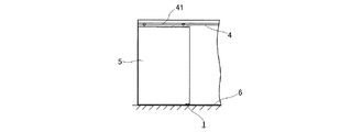
このように構成される本実施の形態は図4に示すように、例えば、鴨居4に取り付けたレール41に懸吊された吊戸本体5の引き込み側の下端部に位置する床面6に取り付けて使用される。
As shown in FIG. 4, this embodiment configured as described above is attached to the
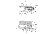
図5及び図6は取付状態及び調整状態を示すものであり、始めに図5に示すように床面6の吊戸本体5の走行方向の中心に沿う中心軸線Cの所定位置に軸孔21を合わせて例えば図示のように基端側のガイドローラ3aが吊戸本体5の下端に沿って形成されたガイド溝51の引き込み側の内側面51cに当接する位置に配置するとともに、軸孔21および取付けねじ孔22,23に取付ねじ71,72,73をそれぞれ挿入して床面6に仮止めしておく。
FIGS. 5 and 6 show an attachment state and an adjustment state. First, as shown in FIG. 5, the
そして、次に、図6に示すように、基板2を取付ねじ61である支軸を中心として水平方向に回転させ、例えば基端側のガイドローラ3aのローラ本体32をガイド溝51の手前側の内側面51aに、先端側のガイドローラ3bのローラ本体32をガイド溝51の手前側の内側面51bにそれぞれ当接させる。
Next, as shown in FIG. 6, the
このとき、ガイドローラ3a,3bは吊戸本体5をガイドすればよく、圧接すると接触抵抗が増して吊戸本体5の走行に影響を与えるので注意を要する。
At this time, the
そして、基板の所定のり回転位置が定まったならば、前記取付ねじ71,72,73を螺締して基板2を床面6に固定する。
When the predetermined rotational position of the substrate is determined, the
このようにして床面6に設置された本実施の形態であるガイド1によると、基端側のガイドローラ3aのローラ本体32をガイド溝51の手前側の内側面51aに、先端側のガイドローラ3bのローラ本体32をガイド溝51の手前側の内側面51bにそれぞれ当接しているので、吊戸本体5は図6の(a)に図示したように、矢印で示すA方向には振れない。また、先端側のガイドローラ3bはガイド溝51の手前側の内側面51bに当接しているので振れることになるが吊戸本体5は基本的に前記図4に示したように直線上のレール41によって移動を規制されているのでガイドローラ3a,3bはいずれもガイドとしての役割を果たしているので厚さ方向に振れる心配はない。また、このように本実施の形態では、ガイドローラ3a,3bと吊戸本体5とが強制的に接していないので、例えば吊戸本体5に衝撃が加わっても吊戸本体5がガイド1により破損したりする心配がない。
In this way, according to the
尚、本実施の形態では、吊戸5の引き込み側に手前側のガイドローラ3aを配置したが、これに限るものでなく、ガイドローラ3a,3bの位置は逆であっても良い。また、本実施の形態では前記取付ねじ71,72,73をいずれも床面6に螺締するものを用いたが、その内の少なくとも1つは床面6に対して支点としての働きをすればよく、螺締するものでなくても良い。
In the present embodiment, the
図7及び図8は本発明の異なる実施の形態を示すものであり、基板2及びガイドローラ3a,3bなどの構成は前記実施の形態とほぼ同様であるが、前記基板2の下面に基板2を前記軸孔21において挿通支持した支軸24によりこの支軸24中心として回転可能に床面取付板8が付設されている点が異る。
7 and 8 show different embodiments of the present invention, and the configuration of the
特に本実施の形態では、基板2には軸孔21を中心とした1つの円弧状の取付けねじ孔22が形成されて、その下方に位置する床面取付板8形成したねじ孔81に短尺の止めねじ74を螺締するものであり、回転調整が1つの止めねじ74で可能とされており、更に、床面取付板8の走行方向の両端に幅方向に延びるねじ孔82,83が形成されており、取り付けねじ75,76により厚さ方向(前後方向)に移動可能に床面6に取り付けることができる。
In particular, in the present embodiment, one arcuate
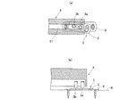
尚、図9は従来のガイドピン形のガイドローラを用いた従来例に本発明を実施した場合の一例を示すものであり、このようにガイド1を変更するだけで従来の吊戸5を用いても実施することができる。
FIG. 9 shows an example in which the present invention is applied to a conventional example using a conventional guide pin type guide roller, and the
1 ガイド、 2 基板、 3a,3bガイドローラ、 4 支持部片、5 吊戸本体、 6 床面、 8 床面取付板、 21 軸孔、 22 取付けねじ孔、 23 取付けねじ孔、 71,72,73 取付ねじ
DESCRIPTION OF
Claims (4)
The guide of the sliding door of Claim 3 with which the said floor surface mounting plate has a mounting part which can move to the thickness direction of a hanging door main body.
Priority Applications (1)
| Application Number | Priority Date | Filing Date | Title |
|---|---|---|---|
| JP2005380639A JP2007182675A (en) | 2005-12-29 | 2005-12-29 | Guide of top-hinged swinging door |
Applications Claiming Priority (1)
| Application Number | Priority Date | Filing Date | Title |
|---|---|---|---|
| JP2005380639A JP2007182675A (en) | 2005-12-29 | 2005-12-29 | Guide of top-hinged swinging door |
Publications (1)
| Publication Number | Publication Date |
|---|---|
| JP2007182675A true JP2007182675A (en) | 2007-07-19 |
Family
ID=38338987
Family Applications (1)
| Application Number | Title | Priority Date | Filing Date |
|---|---|---|---|
| JP2005380639A Withdrawn JP2007182675A (en) | 2005-12-29 | 2005-12-29 | Guide of top-hinged swinging door |
Country Status (1)
| Country | Link |
|---|---|
| JP (1) | JP2007182675A (en) |
Cited By (3)
| Publication number | Priority date | Publication date | Assignee | Title |
|---|---|---|---|---|
| CN104563698A (en) * | 2014-12-25 | 2015-04-29 | 广西优窗特投资有限公司 | Door-window sliding device |
| CN105525823A (en) * | 2016-01-29 | 2016-04-27 | 林维海 | Adjustable movable door bumper stopper |
| CN111719982A (en) * | 2020-06-02 | 2020-09-29 | 南京天普机电产品制造有限公司 | High-speed railway door with prevent pressing from both sides function |
-
2005
- 2005-12-29 JP JP2005380639A patent/JP2007182675A/en not_active Withdrawn
Cited By (3)
| Publication number | Priority date | Publication date | Assignee | Title |
|---|---|---|---|---|
| CN104563698A (en) * | 2014-12-25 | 2015-04-29 | 广西优窗特投资有限公司 | Door-window sliding device |
| CN105525823A (en) * | 2016-01-29 | 2016-04-27 | 林维海 | Adjustable movable door bumper stopper |
| CN111719982A (en) * | 2020-06-02 | 2020-09-29 | 南京天普机电产品制造有限公司 | High-speed railway door with prevent pressing from both sides function |
Similar Documents
| Publication | Publication Date | Title |
|---|---|---|
| JP5913110B2 (en) | Roller assembly for vehicle sliding opening / closing body | |
| JP2007182675A (en) | Guide of top-hinged swinging door | |
| JPH1061322A (en) | Triple sliding door | |
| KR20180001371U (en) | Stay Bar for Turning Type Window | |
| EP2913467A1 (en) | Sliding door upper guide | |
| JP6082590B2 (en) | Runner structure for sliding doors | |
| JP2002242536A (en) | Interlocked sliding door device | |
| JP3007619B1 (en) | Sliding door device | |
| KR101698458B1 (en) | Interlocking device for sliding windows and doors | |
| JP2002349131A (en) | Brace device for sliding door | |
| JP5595996B2 (en) | Sliding door guidance device | |
| KR200188830Y1 (en) | Roller assembly for sliding door | |
| KR20210074886A (en) | Structure of x-type guide bar for preventing movement of opposed type sliding doors | |
| KR200447878Y1 (en) | Sliding guide device of folding door | |
| JP2005113396A (en) | Smoke shielding type sliding door device | |
| JP3107342B2 (en) | sliding door | |
| JP4207575B2 (en) | Elevator door equipment | |
| JP7116601B2 (en) | sliding door device | |
| JP2006239031A (en) | Curtain rail device | |
| JP2006131314A (en) | Door device for elevator | |
| JP4477462B2 (en) | Door sealing device | |
| CN110273608B (en) | Door and window pulley, door and window sash body and door and window | |
| JP6585004B2 (en) | Joinery | |
| JP4347605B2 (en) | Sliding door runner device | |
| JP3590691B2 (en) | Door opening and closing device |
Legal Events
| Date | Code | Title | Description |
|---|---|---|---|
| A300 | Withdrawal of application because of no request for examination |
Free format text: JAPANESE INTERMEDIATE CODE: A300 Effective date: 20090303 |