JP2007147585A - Apparatus for measuring liquid refractive index - Google Patents
Apparatus for measuring liquid refractive index Download PDFInfo
- Publication number
- JP2007147585A JP2007147585A JP2006067904A JP2006067904A JP2007147585A JP 2007147585 A JP2007147585 A JP 2007147585A JP 2006067904 A JP2006067904 A JP 2006067904A JP 2006067904 A JP2006067904 A JP 2006067904A JP 2007147585 A JP2007147585 A JP 2007147585A
- Authority
- JP
- Japan
- Prior art keywords
- refractive index
- optical fiber
- light
- sensor
- emitting diode
- Prior art date
- Legal status (The legal status is an assumption and is not a legal conclusion. Google has not performed a legal analysis and makes no representation as to the accuracy of the status listed.)
- Pending
Links
Images


Abstract
Description
本発明は、アルコール等の屈折率の測定に好適な液体屈折率測定装置に関するものである。 The present invention relates to a liquid refractive index measuring apparatus suitable for measuring a refractive index of alcohol or the like.
特開2001−083084号公報(特許文献1)に光ファイバーによる溶液の屈折率測定法が開示されている。この公報には、「入射光に角度幅を持たせると、光伝達の原理よりファイバー周囲の液体の屈折率に応じた一定の入射角内の光線しか伝達されず、それ以上の入射角の光線はファイバーから漏れる原理に基づくものである。」という記載がある。 Japanese Patent Laid-Open No. 2001-083084 (Patent Document 1) discloses a method for measuring the refractive index of a solution using an optical fiber. According to this publication, “If the incident light has an angular width, only light within a certain incident angle according to the refractive index of the liquid surrounding the fiber is transmitted by the principle of light transmission, and light with an incident angle higher than that is transmitted. Is based on the principle of leaking from the fiber. "
特開2004−191110号公報(特許文献2)には、金を蒸着した光ファイバーコアによる屈折率測定用センサーが開示されている。この公報には、「光源部としてレーザとレンズ、センサー部としてガラス管に金蒸着光ファイバーと試料導入用のチューブを固定したセンサーを持ち、検出部として検出器とマルチメーター、記録部としてレコーダーとコンピュータを持ったものである。」という記載がある。 Japanese Patent Application Laid-Open No. 2004-191110 (Patent Document 2) discloses a sensor for measuring a refractive index using an optical fiber core deposited with gold. In this publication, “a laser and a lens as a light source part, a sensor having a gold vapor deposition optical fiber and a sample introduction tube fixed to a glass tube as a sensor part, a detector and a multimeter as a detection part, a recorder and a computer as a recording part” There is a description of ".
学術論文分析化学、52巻、第6号、433〜438ページ、2003年(非特許文献1)には、露出させたコアを90度ずつ回転させ、金蒸着を4回繰り返した光ファイバーを用いたセンサーによるアルコールの屈折率測定が開示されている。 Academic Paper Analytical Chemistry, Vol. 52, No. 6, pages 433-438, 2003 (Non-Patent Document 1) used an optical fiber in which the exposed core was rotated by 90 degrees and gold deposition was repeated four times. Measuring the refractive index of alcohol with a sensor is disclosed.
学術論文Analytical Sciences、18巻、第3号、261〜265ページ、2002年(非特許文献2)には、プリズム上に真空蒸着した金薄膜層に被覆膜層を形成した表面プラズモン共鳴センサーによるアミンの高感度検出が開示されている。 Academic paper Analytical Sciences, Vol. 18, No. 3, pp. 261-265, 2002 (Non-Patent Document 2) is based on a surface plasmon resonance sensor in which a coating film layer is formed on a gold thin film layer vacuum-deposited on a prism. Sensitive detection of amines is disclosed.
学術論文Analytical Sciences、第20巻、第4号、689〜694ページ、2004年(非特許文献3)には、レーザと単球面レンズを光源部とし、センサーとしてコア上に金を一回蒸着した光ファイバーを用いることにより、市販のアッベ屈折率計よりも高い感度を持った屈折率測定装置が示されている。 In the scientific paper Analytical Sciences, Vol. 20, No. 4, pages 689-694, 2004 (Non-patent Document 3), a laser and a single spherical lens were used as a light source part, and gold was deposited once on the core as a sensor. A refractive index measuring device having higher sensitivity than a commercially available Abbe refractometer by using an optical fiber is shown.
しかしながら、特許文献1には、複数のレンズを用いて複雑な光学系とし、平行光に角度幅を持たせて入射する必要があるという問題点があり、光学系の調整が難しい。その結果、収差等により精度及び再現性に問題がある。
However,
特許文献2は、レーザ、単球面レンズとからなる光源部と、屈折率測定用センサーとこれを固定するガラス管と試料を流入・排出するチューブとを主な構成とするセンサー部と、サンプル容器とポンプから構成される試料部を必要とするため、小型化するためには制約がある。また、レーザ光は目に与える負担が大きく、取り扱いに注意を要する。さらにレーザは発光時の消費電力が大きいため、電池等の小電力で稼働するシステムを構築するには不都合である。 Patent Document 2 discloses a light source unit composed of a laser and a single spherical lens, a sensor unit mainly composed of a refractive index measuring sensor, a glass tube for fixing the sensor, and a tube for inflowing / extracting a sample, and a sample container Therefore, there is a restriction for downsizing. In addition, the laser beam has a large burden on the eyes, and needs to be handled with care. Furthermore, since the laser consumes a large amount of power when emitting light, it is inconvenient for constructing a system that operates with low power such as a battery.
非特許文献1は光ファイバーへ金を4回蒸着するのに高い技術を要すること、また測定の精度のさらなる向上が望まれる。
Non-Patent
非特許文献2は、プリズムや角度を調整するための装置が必要であり、光ファイバーを用いていないため、遠隔分析するためにはさらなる改良が必要であり、装置を使用できる場所が制限される。 Non-Patent Document 2 requires a prism and a device for adjusting the angle and does not use an optical fiber. Therefore, further improvement is necessary for remote analysis, and the place where the device can be used is limited.
非特許文献3は、レーザを光源とし、光ファイバー上に金を一回蒸着することで非特許文献1で示された屈折率測定装置の性能向上に成功しているが、光源にレーザを用いているために扱いが難しく、更に小型化が望まれる。
Non-Patent Document 3 has succeeded in improving the performance of the refractive index measuring apparatus shown in Non-Patent
本発明は、幅広い産業分野に適用でき、容易に小型化することができ、且つ、安全性、信頼性及び精度が高い屈折率測定装置を提供することを目的とする。 An object of the present invention is to provide a refractive index measuring apparatus that can be applied to a wide range of industrial fields, can be easily downsized, and has high safety, reliability, and accuracy.
本願発明者は、鋭意研究の結果、発光ダイオードでも表面プラズモン共鳴効果が得られることを見出し、光ファイバーへの光の入射方法を工夫することで上記問題を解決した。即ち、光源に発光ダイオードを用いることにより、人体に与える影響をなくすると同時に消費電力を減らすことに成功した。更に、金属薄膜層を形成する媒体としてガラス棒を使用しても光ファイバーと同等の結果が得られることを見出し、用途に応じて光ファイバーとガラス棒とを使い分けることで、幅広い産業分野に適用できるセンサー部を開発した。更に、光ファイバーを光源に直接密接又は近接させることによってレンズや光軸合わせを不要とし、センサーを透過してきた光信号を演算処理した後に表示部にてデジタル表示にすることにより、装置の小型化に成功した。また、光源部と表示部を一つの回路上に形成することにより、更に小型で取り扱いの容易な液体屈折率測定装置を提供することができる。 As a result of earnest research, the inventor of the present application has found that a surface plasmon resonance effect can be obtained even with a light-emitting diode, and has solved the above problem by devising a method of injecting light into an optical fiber. That is, by using a light emitting diode as a light source, it has succeeded in eliminating the influence on the human body and at the same time reducing the power consumption. Furthermore, even if a glass rod is used as a medium for forming a metal thin film layer, it is found that the same result as that of an optical fiber can be obtained, and a sensor that can be applied to a wide range of industrial fields by properly using an optical fiber and a glass rod depending on the application. Department developed. In addition, the optical fiber is directly in close proximity to or close to the light source, eliminating the need for lens and optical axis alignment, and processing the optical signal that has passed through the sensor to digital display on the display unit, thereby reducing the size of the device. Successful. Further, by forming the light source unit and the display unit on one circuit, it is possible to provide a liquid refractive index measuring device that is smaller and easy to handle.
本発明に係る液体屈折率測定装置は、発光ダイオードと、前記発光ダイオードにより発せられた光に対して、その表面に接触している液体試料の屈折率に応じた表面プラズモン共鳴現象を発生させる検出手段と、前記検出手段から出力された光に基づいて前記液体試料の屈折率を求める演算手段と、を有することを特徴とする。 The liquid refractive index measuring device according to the present invention is a light emitting diode and a detection for generating a surface plasmon resonance phenomenon corresponding to the refractive index of a liquid sample in contact with the surface of the light emitted from the light emitting diode. And a calculating means for obtaining a refractive index of the liquid sample based on the light output from the detecting means.
本発明によれば、発光ダイオードを光源として用いているため、小型化が可能となると共に、消費電力を抑制することができる。また、発光ダイオードは出力が安定しているため、高い信頼性及び精度を得ることができる。また、レーザと比較して高い安全性も得ることができる。 According to the present invention, since the light emitting diode is used as the light source, the size can be reduced and the power consumption can be suppressed. In addition, since the output of the light emitting diode is stable, high reliability and accuracy can be obtained. In addition, high safety can be obtained as compared with a laser.
以下に、本発明の実施形態に係る液体屈折率測定装置及びその使用方法について、添付の図面を参照しながら詳細に説明する。図1は、本発明の実施形態に係る液体屈折率測定装置の概略構成を示す図である。本実施形態に係る液体屈折率測定装置には、光源部10、センサー部20及び表示部30が設けられている。但し、本発明はこれに限定されるものではない。ここでは液体の屈折率を測定し、これによって液体の混合比や濃度、酒類のアルコール度数を求めることができる。
Hereinafter, a liquid refractive index measurement device and a method of using the same according to an embodiment of the present invention will be described in detail with reference to the accompanying drawings. FIG. 1 is a diagram showing a schematic configuration of a liquid refractive index measurement apparatus according to an embodiment of the present invention. The liquid refractive index measurement device according to the present embodiment includes a
光源部10には、発光ダイオード11、信号伝達用光ファイバー12及び光ファイバー接続用器具13が設けられている。発光ダイオード11からの信号伝達用光ファイバー12への光の入射は、端面を劈開処理した光ファイバー12を発光ダイオード11に直接密接又は近接させることで実現可能である。
The
センサー部20には、屈折率測定用センサー21、補強材22及び信号伝達用光ファイバー23が設けられている。屈折率測定用センサー21は、例えば、薬品によりコア(光ファイバーコア)を露出させた光ファイバーの表面上に真空蒸着法により金属薄膜層を形成することにより作製されている。屈折率測定用センサーの長さは3〜100mm程度であるが、例えば、光ファイバーコアをアセトンで脱脂し、固定器具で蒸着源から適切な距離に設置することにより、短い屈折率測定用センサーへもムラのない金属薄膜層として金薄膜を形成することができる。そして、このようにして作製された屈折率測定用センサー21が補強材22に固定されている。なお、光ファイバーコアの代わりにガラス棒を用いてもよい。このような屈折率測定用センサー21に液体サンプルが接触すると、表面プラズモン共鳴現象が発生する。即ち、液体サンプルの屈折率に応じて屈折率測定用センサー21から出力される光(屈折率測定用センサー21を透過する光)の強度が変化する。なお、屈折率測定用センサー21が液体サンプルと接触すれば応答が得られるので、補強材22は管状である必要はなく、また、補強材22自体が設けられていなくてもよい。信号伝達用光ファイバー23は、光ファイバー接続用器具13及び後述の光ファイバー接続用器具31を介して、それぞれ光源部10及び表示部30に接続される。
The
表示部30には、光ファイバー接続用器具31、信号伝達用光ファイバー32、受光素子33、抵抗素子34、増幅部35、A/Dコンバータ36、演算部37、ディスプレイ38及びアース39が設けられている。接続用器具31及び光ファイバー32を介して受光素子33に光が入射すると、その強度に応じて電流が発生する。そして、この電流が抵抗素子34によって電圧に変換され、増幅部35により増幅され、A/Dコンバータ36へと入力される。A/Dコンバータ36によってデジタル信号に変換された信号は演算部37に入力され、演算部37は入力されたデジタル信号を用いて液体サンプルの屈折率及びアルコール度数を計算し、ディスプレイ38にて結果を表示する。演算部37の動作はプログラムで制御を行うことが可能であり、警告音を用いた屈折率監視及び/又はバルブの開閉等による機器(図示せず)の制御を行うことも可能である。
The
このような液体屈折率測定装置においては、光源部10の発光ダイオード11から発せられた光がセンサー部20へ入射する。センサー部20では、屈折率測定用センサー21において、表面プラズモン共鳴現象が発生するため、センサー部20からの透過光が変化する。そして、この透過光の変化が受光素子33にて検出され、検出された透過光の変化が増幅部35、A/Dコンバータ36及び演算部37を経てディスプレイ38へ出力される。
In such a liquid refractive index measurement device, light emitted from the light emitting diode 11 of the
このような液体屈折率測定装置によれば、単純な光学系で広い範囲の屈折率の測定を行うことができる。特に、発光ダイオード11で十分であり、レーザは不要であるため、小型化に適しており、また、取り扱いも容易である。更に、光ファイバーを使用することによって、中継や増幅を行わずに遠隔地における連続的屈折率測定も可能である。即ち、このような液体屈折率測定装置を用いて、液体の製造ラインにおける屈折率測定による分析及び/又は品質遠隔管理システムを構築することも可能である。例えば、センサー部20からの信号が、予め設定された条件を満たした場合に、ブザー等の音で警告をする屈折率監視機構及び/又はバルブの開閉等による機器制御機構を構成してもよい。
According to such a liquid refractive index measuring apparatus, a wide range of refractive indexes can be measured with a simple optical system. In particular, the light-emitting diode 11 is sufficient, and a laser is unnecessary. Therefore, the light-emitting diode 11 is suitable for downsizing and easy to handle. Furthermore, by using an optical fiber, it is possible to measure a continuous refractive index in a remote place without relaying or amplifying. That is, by using such a liquid refractive index measuring device, it is also possible to construct an analysis and / or quality remote control system by refractive index measurement in a liquid production line. For example, a refractive index monitoring mechanism that warns with a sound such as a buzzer when the signal from the
なお、屈折率測定用センサー21に光ファイバーコアを使用する場合、光ファイバーコアとしては、例えば、高屈折率の光伝達媒体を低屈折率のポリマー等で被覆して構成された市販の光ファイバーから、被覆した部分(低屈折率のポリマー等)を取り除いたものを用いることができる。
When an optical fiber core is used for the refractive
屈折率測定用センサー21としては、例えば、金、銀、銅若しくはアルミニウムの単膜、又は、銀、銅及び/若しくはアルミニウムの膜と金膜との多層構造の金属膜を光ファイバーコア又はガラス棒の表面上に蒸着したものを用いることができる。金属膜の厚さの合計は、10nm〜70nmとすることが好ましい。また、その端面は劈開処理しておくことが好ましい。
As the refractive
屈折率測定用センサー21を構成する光伝達部材の材質を、機械的強度に優れた石英ガラス棒と小型センサーを構築できる光ファイバーコアとから用途に応じて選択することにより、幅広い産業分野に適用できる屈折率測定用センサーを提供できる。
By selecting the material of the light transmission member constituting the refractive
また、発光ダイオード11としては、単色光又は白色光を発するものを用いることができる。 Moreover, as the light emitting diode 11, what emits monochromatic light or white light can be used.
また、受光素子33として、フォトダイオード等を使用することができる。 A photodiode or the like can be used as the light receiving element 33.
また、光源部10とセンサー部20との間にレンズは不要である。
Further, no lens is required between the
また、表示部30は、液体サンプルの屈折率そのものだけでなく、屈折率から求められたアルコール度数等を表示してもよい。
The
また、発光ダイオード11又は受光素子33を屈折率測定用センサー21に密接させるか、又は接近させることが可能であれば、信号伝達用光ファイバー12及び32、並びに、光ファイバー接続用器具13、23及び31を設けなくてもよい。即ち、発光ダイオード11から屈折率測定用センサー21に直接光を入射したり、屈折率測定用センサー21からの出力を直接測定したりしてもよい。
Further, if the light emitting diode 11 or the light receiving element 33 can be brought into close contact or close to the refractive
液体サンプルとしては、水及び/又は有機物を溶媒としたものを用いることが好ましく、センサーを腐食しないことがより好ましい。 As the liquid sample, it is preferable to use water and / or an organic substance as a solvent, and it is more preferable not to corrode the sensor.
本発明において、色又は光の放射の形状が異なる直径5mmの発光ダイオード11を用いた場合の屈折率に対する応答特性を図2に示す。屈折率測定用センサー21として、長さが10cmの光ファイバーコアの表面に45nmの金膜を蒸着したものを使用した。図2の赤色の発光ダイオードにおいて広指向タイプと中指向タイプがあるが、広指向タイプでは光が発光点から放射状に広がり、中指向タイプでは光が特定の方向に集光するようになっており、どちらも市販のものである。屈折率はエチレングリコールのメタノール溶液の濃度を変化させることにより調節した。本実験により、発光ダイオードの色を変えるだけで応答範囲や感度などのセンサーの特性を制御できることが示された。
FIG. 2 shows the response characteristics with respect to the refractive index when the light-emitting diode 11 having a diameter of 5 mm having a different color or light emission shape is used. As the refractive
(比較例1)
光源部10の代わりにHe−Neレーザを用い、センサーを透過してきた光の強度をSi検出器を用いて測定し、光マルチメーター及びデジタルマルチメーターを介してコンピュータで解析を行った場合の屈折率に対する応答特性を図3に示す。屈折率測定用センサーとして、長さが10cmの光ファイバーコアの表面に45nmの金膜を蒸着したものを使用し、各種アルコールのメタノール溶液を用いて測定を行った。実施例1に類似した応答特性を持っているが、装置が非常に大きく、携帯には不向きである。
(Comparative Example 1)
Refraction when a He—Ne laser is used instead of the
光源を直径3mmの発光ダイオード11とし、屈折率を変化させた場合のセンサーを透過してきた光の強度変化を測定したものを図4に示す。屈折率測定用センサー21として、長さが10cmの光ファイバーコアの表面に45nmの金膜を蒸着したものを使用し、測定試料としてエチレングリコールのメタノール溶液を使用した。直径の小さい発光ダイオード11でも十分な応答が得られた。また、白色の発光ダイオード11においてもセンサーシステムを構築することができた。
FIG. 4 shows the intensity change of light transmitted through the sensor when the light source is a light emitting diode 11 having a diameter of 3 mm and the refractive index is changed. As the refractive
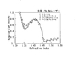
本発明による直径5mmの赤色発光ダイオード11(広指向タイプ)を用いた場合の1.330〜1.353の範囲の屈折率の微少な変化に対する応答特性(検量線)を図5に示す。屈折率測定用センサーとして、長さが10cmの光ファイバーコアの表面に45nmの金膜を蒸着したものを使用した。測定試料として、ベンジルアルコールのメタノール溶液を用いた。相関係数が0.996の直線上に乗っており、小さな屈折率の変化も定量的に測定が可能であることが示された。 FIG. 5 shows a response characteristic (calibration curve) for a slight change in refractive index in the range of 1.330 to 1.353 when the red light emitting diode 11 (wide directional type) having a diameter of 5 mm according to the present invention is used. As a sensor for refractive index measurement, a metal film having a 45 nm gold film deposited on the surface of an optical fiber core having a length of 10 cm was used. As a measurement sample, a methanol solution of benzyl alcohol was used. The correlation coefficient is on a straight line of 0.996, indicating that small changes in refractive index can be measured quantitatively.
図6に、本発明を用いた蒸留酒のエタノール濃度測定の結果を示す。光源には直径5mmの赤色発光ダイオードを使用した。本実施例では、15℃で0〜50度の検量線を、長さが10cmの光ファイバーコアの表面に45nmの金膜を蒸着した屈折率測定用センサー21を用いて予め作成しておき、その後、試料を測定して濃度を算出した。本発明においては、あらかじめ検量線を演算部に登録しておくことで瞬時に度数を測定することも可能である。表面プラズモン共鳴現象を用いているために、試料の着色の有無にかかわらずエタノール濃度を求めることができる。本実施例において、焼酎2銘柄(白波(商標)、伊佐錦(商標))、ウィスキー、ブランデー、ジン、ウォッカ、ラム、テキーラの濃度を正確に求めることに成功しており、産業への応用も可能であることが示された。
In FIG. 6, the result of the ethanol concentration measurement of distilled liquor using this invention is shown. A red light emitting diode having a diameter of 5 mm was used as the light source. In this example, a calibration curve of 0 to 50 degrees at 15 ° C. was prepared in advance using the refractive
図7に直径5mmの赤色発光ダイオード11(広指向タイプ)を用いて測定した15℃におけるエタノール水溶液の検量線と3回の測定における相対標準偏差を示す。屈折率測定用センサー21として、長さが10cmの光ファイバーコアの表面に45nmの金膜を蒸着したものを使用した。エタノール濃度の増加に応じて応答曲線が単調に減少している。各点の相対標準偏差は最大で0.07%であり、高い精度で濃度の測定を行うことができた。
FIG. 7 shows a calibration curve of an aqueous ethanol solution at 15 ° C. measured using a red light emitting diode 11 (wide directional type) having a diameter of 5 mm and a relative standard deviation in three measurements. As the refractive
(比較例2)
図8に光源にHe−Neレーザを用い、光ファイバーを透過してくる光の強度変化を観測した場合の25℃におけるエタノール水溶液の検量線と3回の測定における相対標準偏差を示す。屈折率測定用センサーとして、長さが10cmの光ファイバーコアの表面に45nmの金膜を蒸着したものを使用した。濃度に応じた単調減少の応答曲線が得られたが、各点の相対標準偏差は最大で1.8%であり、精度の点でやや不満がある。
(Comparative Example 2)
FIG. 8 shows a calibration curve of an aqueous ethanol solution at 25 ° C. and a relative standard deviation in three measurements when a He—Ne laser is used as a light source and an intensity change of light transmitted through an optical fiber is observed. As a sensor for refractive index measurement, a metal film having a 45 nm gold film deposited on the surface of an optical fiber core having a length of 10 cm was used. Although a monotonically decreasing response curve according to the concentration was obtained, the relative standard deviation of each point was 1.8% at the maximum, which is somewhat dissatisfied with respect to accuracy.
図9に、屈折率測定用センサー21として、直径が1mm、2mm、2.5mm、5mmの石英ガラス棒の表面に金膜を形成したものを使用し、この屈折率測定用センサー21を発光ダイオード11及び受光素子33に直接接触させたセンサーシステムによる屈折率に対する応答特性を示す。屈折率はエタノール水溶液又はエチレングリコールのメタノール溶液を用いて調整した。なお、2mmのものは、広屈折率範囲にわたって測定された結果の抜粋である。図9に示すように、すべての直径のガラス棒において屈折率の増加に伴って透過光の強度が減少しており、ガラス棒においても良好な応答が得られた。また、2mm以下のガラス棒において、高い感度が得られた。これらの結果から、ガラス棒でも十分な応答が得られることを確かめることができ、更にガラス棒の直径を選択することで最適な強度や感度を選択できることが示された。
In FIG. 9, a refractive
本発明において、色が異なる直径5mmの発光ダイオード11を用いた場合の屈折率に対する応答特性を図10に示す。屈折率測定用センサー21として、直径2mmの石英ガラス棒の表面に45nmの金膜を形成したものを使用した。屈折率はエチレングリコールのメタノール溶液の濃度を変化させることにより調節した。発光ダイオードの色を変えることにより光ファイバーの場合と同様に高い感度を持ちながら応答特性を変化させることができた。
FIG. 10 shows the response characteristics with respect to the refractive index when the light emitting diode 11 having a diameter of 5 mm and having a different color is used in the present invention. As the refractive
本発明において、屈折率測定用センサー21として、直径2mmの石英ガラス棒を加熱してU字型に変形させ、その下面に45nmの金膜を形成したセンサーの屈折率に対する応答特性を図11に示す。光源には直径5mmの赤色発光ダイオード11を使用した。屈折率はエチレングリコールのメタノール溶液の濃度を変化させることにより調節した。これらの結果から、曲率半径が大きくなると良好な応答が得られ、適度な曲率なら変形したガラス棒をセンサーとして使用できることがわかった。
In the present invention, as a refractive
(比較例3)
図12に曲率半径21mmで金を蒸着していないガラス棒の屈折率に対する応答特性を示す。屈折率はエチレングリコールのメタノール溶液の濃度を変化させることにより調節した。ガラス棒において、金薄膜を蒸着しない場合は表面プラズモン共鳴効果が起こらず、応答を示さないことが示された。
(Comparative Example 3)
FIG. 12 shows the response characteristics with respect to the refractive index of a glass rod having a radius of curvature of 21 mm and not deposited with gold. The refractive index was adjusted by changing the concentration of the ethylene glycol methanol solution. It was shown that the surface plasmon resonance effect did not occur in the glass rod when no gold thin film was deposited, and no response was shown.
10 光源部
20 センサー部
30 表示部
11 発光ダイオード
12 信号伝達用光ファイバー
13 光ファイバー接続用器具
21 屈折率測定用センサー
22 屈折率測定用センサー補強材
23 信号伝達用光ファイバー
31 光ファイバー接続用器具
32 信号伝達用光ファイバー
33 受光素子
34 抵抗素子
35 増幅部
36 A/Dコンバータ
37 演算部
38 ディスプレイ
39 アース
DESCRIPTION OF
Claims (5)
前記発光ダイオードにより発せられた光に対して、その表面に接触している液体試料の屈折率に応じた表面プラズモン共鳴現象を発生させる検出手段と、
前記検出手段から出力された光に基づいて前記液体試料の屈折率を求める演算手段と、
を有することを特徴とする液体屈折率測定装置。 A light emitting diode;
Detection means for generating a surface plasmon resonance phenomenon corresponding to the refractive index of the liquid sample in contact with the surface of the light emitted by the light emitting diode;
A calculation means for obtaining a refractive index of the liquid sample based on the light output from the detection means;
A liquid refractive index measuring apparatus comprising:
光伝達部材と、
前記光伝達部材の表面に形成された金属膜と、
を有することを特徴とする請求項1に記載の液体屈折率測定装置。 The detection means includes
A light transmission member;
A metal film formed on the surface of the light transmission member;
The liquid refractive index measuring device according to claim 1, wherein
Priority Applications (1)
| Application Number | Priority Date | Filing Date | Title |
|---|---|---|---|
| JP2006067904A JP2007147585A (en) | 2005-03-17 | 2006-03-13 | Apparatus for measuring liquid refractive index |
Applications Claiming Priority (3)
| Application Number | Priority Date | Filing Date | Title |
|---|---|---|---|
| JP2005077394 | 2005-03-17 | ||
| JP2005322428 | 2005-11-07 | ||
| JP2006067904A JP2007147585A (en) | 2005-03-17 | 2006-03-13 | Apparatus for measuring liquid refractive index |
Publications (1)
| Publication Number | Publication Date |
|---|---|
| JP2007147585A true JP2007147585A (en) | 2007-06-14 |
Family
ID=38209139
Family Applications (1)
| Application Number | Title | Priority Date | Filing Date |
|---|---|---|---|
| JP2006067904A Pending JP2007147585A (en) | 2005-03-17 | 2006-03-13 | Apparatus for measuring liquid refractive index |
Country Status (1)
| Country | Link |
|---|---|
| JP (1) | JP2007147585A (en) |
Cited By (5)
| Publication number | Priority date | Publication date | Assignee | Title |
|---|---|---|---|---|
| JP2010223732A (en) * | 2009-03-23 | 2010-10-07 | Aisan Ind Co Ltd | Fuel property determination device |
| JP2016507068A (en) * | 2013-02-20 | 2016-03-07 | クロマリティカ エービー | New apparatus and method for analyzing samples and use thereof |
| CN105403536A (en) * | 2015-12-22 | 2016-03-16 | 北京大学 | Nanowire-based liquid refractive index probe and detection system and detecting method thereof |
| CN111830025A (en) * | 2020-07-21 | 2020-10-27 | 宿迁学院 | Online measuring device for electrolytic machining |
| DE112020001169T5 (en) | 2019-03-11 | 2021-12-02 | Denso Corporation | Wheel control system and method |
Citations (5)
| Publication number | Priority date | Publication date | Assignee | Title |
|---|---|---|---|---|
| JPH10253531A (en) * | 1997-03-12 | 1998-09-25 | Masami Ogita | Method for measuring critical micell concentration, and apparatus therefor |
| JP2002162346A (en) * | 2000-11-22 | 2002-06-07 | Nippon Telegr & Teleph Corp <Ntt> | Light waveguide type spr phenomenon measuring apparatus |
| JP2002340790A (en) * | 2001-05-15 | 2002-11-27 | Suzuki Motor Corp | Spr sensor |
| JP2002357538A (en) * | 2001-05-31 | 2002-12-13 | Suzuki Motor Corp | Plasmon sensor device |
| JP2004191110A (en) * | 2002-12-10 | 2004-07-08 | Masaru Mitsushio | Refractive index measuring device using gold deposition optical fiber |
-
2006
- 2006-03-13 JP JP2006067904A patent/JP2007147585A/en active Pending
Patent Citations (5)
| Publication number | Priority date | Publication date | Assignee | Title |
|---|---|---|---|---|
| JPH10253531A (en) * | 1997-03-12 | 1998-09-25 | Masami Ogita | Method for measuring critical micell concentration, and apparatus therefor |
| JP2002162346A (en) * | 2000-11-22 | 2002-06-07 | Nippon Telegr & Teleph Corp <Ntt> | Light waveguide type spr phenomenon measuring apparatus |
| JP2002340790A (en) * | 2001-05-15 | 2002-11-27 | Suzuki Motor Corp | Spr sensor |
| JP2002357538A (en) * | 2001-05-31 | 2002-12-13 | Suzuki Motor Corp | Plasmon sensor device |
| JP2004191110A (en) * | 2002-12-10 | 2004-07-08 | Masaru Mitsushio | Refractive index measuring device using gold deposition optical fiber |
Cited By (7)
| Publication number | Priority date | Publication date | Assignee | Title |
|---|---|---|---|---|
| JP2010223732A (en) * | 2009-03-23 | 2010-10-07 | Aisan Ind Co Ltd | Fuel property determination device |
| US8260560B2 (en) | 2009-03-23 | 2012-09-04 | Aisan Kogyo Kabushiki Kaisha | Fuel property determining apparatus |
| JP2016507068A (en) * | 2013-02-20 | 2016-03-07 | クロマリティカ エービー | New apparatus and method for analyzing samples and use thereof |
| CN105403536A (en) * | 2015-12-22 | 2016-03-16 | 北京大学 | Nanowire-based liquid refractive index probe and detection system and detecting method thereof |
| DE112020001169T5 (en) | 2019-03-11 | 2021-12-02 | Denso Corporation | Wheel control system and method |
| CN111830025A (en) * | 2020-07-21 | 2020-10-27 | 宿迁学院 | Online measuring device for electrolytic machining |
| CN111830025B (en) * | 2020-07-21 | 2023-10-31 | 宿迁学院 | Electrolytic machining on-line measuring device |
Similar Documents
| Publication | Publication Date | Title |
|---|---|---|
| Iga et al. | Hetero-core structured fiber optic surface plasmon resonance sensor with silver film | |
| US9285534B2 (en) | Fiber-optic surface plasmon resonance sensor and sensing method using the same | |
| US7352468B2 (en) | Cavity ring-down detection of surface plasmon resonance in an optical fiber resonator | |
| JP3152758U (en) | Surface plasma resonance measuring instrument | |
| Niggemann et al. | Remote sensing of tetrachloroethene with a micro-fibre optical gas sensor based on surface plasmon resonance spectroscopy | |
| US20040118997A1 (en) | Tapered fiber optic strain gauge using cavity ring-down spectroscopy | |
| JP2005512079A (en) | Apparatus and method for detection and measurement of trace components | |
| CN101413891B (en) | Optical fiber sensor of plasma resonance microstructure | |
| JP2010014739A (en) | Apparatus for spectroscopic measurement of trace species | |
| JP2007147585A (en) | Apparatus for measuring liquid refractive index | |
| CN102095719A (en) | Optical fiber type sensor system based on surface plasma resonance and stimulated Raman scattering | |
| Iga et al. | Acidity measurements based on a hetero-core structured fiber optic sensor | |
| Hernández et al. | Prism-based surface plasmon resonance for dual-parameter sensing | |
| Zhang et al. | A waveguide-coupled surface plasmon resonance sensor using an Au-MgF 2-Au structure | |
| CN210923475U (en) | Serum albumin detection system based on optical fiber SPR sensor | |
| CN201302543Y (en) | Optical-fiber sensor with plasma resonance microstructure | |
| JP2004170095A (en) | Waveguide structure, its manufacturing method, and surface plasmon resonance sensor and refractive index change measurement method using the waveguide structure | |
| JP3991072B2 (en) | Refractive index sensor, refractive index measuring apparatus, and manufacturing method of refractive index sensor | |
| JP2004245674A (en) | Radiation temperature measuring apparatus | |
| RU2735631C1 (en) | Fibre-optic plasmon sensor of liquid refraction index | |
| Zhou et al. | Multimode optical fiber surface plasmon resonance signal processing based on the Fourier series fitting | |
| CN101093193A (en) | Multiple optical fiber probe with temperature correction | |
| Lobry et al. | New demodulation technique based on spectral envelopes intersection for plasmonic fiber grating sensors | |
| Muthuraju et al. | Low cost fiber optic sensing of sugar solution | |
| JP2005049182A (en) | Fiber optic core refractive index sensor having one layer of deposited silver, copper or aluminum or laminated layer having deposited metal |
Legal Events
| Date | Code | Title | Description |
|---|---|---|---|
| A621 | Written request for application examination |
Effective date: 20090313 Free format text: JAPANESE INTERMEDIATE CODE: A621 |
|
| A977 | Report on retrieval |
Effective date: 20110106 Free format text: JAPANESE INTERMEDIATE CODE: A971007 |
|
| A131 | Notification of reasons for refusal |
Free format text: JAPANESE INTERMEDIATE CODE: A131 Effective date: 20110301 |
|
| A521 | Written amendment |
Effective date: 20110421 Free format text: JAPANESE INTERMEDIATE CODE: A523 |
|
| A02 | Decision of refusal |
Free format text: JAPANESE INTERMEDIATE CODE: A02 Effective date: 20111122 |