JP2007147324A - Surface inspection device - Google Patents
Surface inspection device Download PDFInfo
- Publication number
- JP2007147324A JP2007147324A JP2005338860A JP2005338860A JP2007147324A JP 2007147324 A JP2007147324 A JP 2007147324A JP 2005338860 A JP2005338860 A JP 2005338860A JP 2005338860 A JP2005338860 A JP 2005338860A JP 2007147324 A JP2007147324 A JP 2007147324A
- Authority
- JP
- Japan
- Prior art keywords
- light
- fiber
- inspection apparatus
- light receiving
- surface inspection
- Prior art date
- Legal status (The legal status is an assumption and is not a legal conclusion. Google has not performed a legal analysis and makes no representation as to the accuracy of the status listed.)
- Pending
Links
Images


Abstract
Description
本発明は、被検査物表面に存在する異物、微細な溝又は傷を検査する表面検査装置に関する。 The present invention relates to a surface inspection apparatus for inspecting foreign matter, fine grooves or scratches present on the surface of an object to be inspected.
被検査物表面に存在する溝や傷を検査することのできる装置としては、光源から投光ファイバを介して被検査物の表面に投光された光の反射光を受光ファイバを介して受光し、その受光量に基づいて被検査物の表面に対応した二次元画像を生成し表面の溝や傷を検出する表面検査装置が知られている。この装置は、投光ファイバを介して投光される光を円筒体の内周に沿って回転させる回転手段及び円筒体の軸方向に沿って移動させる直線移動手段も備え、平面のみならず円筒体の内面も検査可能となっている(例えば、特許文献1参照)。
この表面検査装置により、微細な溝や傷を検出するためには、投光ファィバを細くして光の照射スポットを小さくし、分解能を向上させることが必要である。しかし、照射スポットを小さくしていくと、表面の荒れや汚れによる光の散乱の影響を受けやすくなり、検出したい溝とこれらの荒れや汚れとの区別がしにくくなるという問題が生じてくる。このため、従来の表面検査装置を微細な溝の検出に用いることは困難である。 In order to detect fine grooves and scratches with this surface inspection apparatus, it is necessary to make the light emitting fiber thinner to reduce the light irradiation spot and improve the resolution. However, if the irradiation spot is made smaller, it becomes more susceptible to light scattering due to surface roughness and dirt, and there arises a problem that it becomes difficult to distinguish the groove to be detected from these roughness and dirt. For this reason, it is difficult to use a conventional surface inspection apparatus for detecting fine grooves.
そこで、本発明は、表面の荒れや汚れ等の影響を受けにくく、被検査物表面の微細な溝等の欠陥が検査可能な表面検査装置を提供することを目的とする。 SUMMARY OF THE INVENTION An object of the present invention is to provide a surface inspection apparatus that is less susceptible to surface roughness and dirt, and that can inspect defects such as fine grooves on the surface of an object to be inspected.
本発明の表面検査装置は、光源(24)から投光ファイバ(20)を介して被検査物(2)の表面に投光された光(L)の反射光を受光ファイバ(21)を介して受光し、その受光量に基づいて前記被検査物(2)の表面を検査する表面検査装置(1)において、前記投光ファイバ(20)の周囲に前記受光ファイバ(21)を複数配置し、前記受光ファイバ(21)の径を前記投光ファイバ(20)の径よりも大きくすることにより上記課題を解決する。 In the surface inspection apparatus of the present invention, the reflected light of the light (L) projected from the light source (24) onto the surface of the inspection object (2) via the light projecting fiber (20) is transmitted via the light receiving fiber (21). In the surface inspection apparatus (1) for inspecting the surface of the inspection object (2) based on the amount of received light, a plurality of the light receiving fibers (21) are arranged around the light projecting fiber (20). The above-mentioned problem is solved by making the diameter of the light receiving fiber (21) larger than the diameter of the light projecting fiber (20).
上述のように、表面検査装置において、分解能を向上させるために投光ファイバを細くしていくと、表面の浅い部分に存在する荒れや汚れによる光の散乱が反射光に及ぼす影響が大きくなってくる。しかし、この場合であっても、溝や傷の部分からの反射光と比べると、正反射の量が多くまた投光位置からの散乱光の広がりも小さい。本発明の表面検査装置は、投光ファイバの周囲に、複数の受光ファイバが配置され且つ受光ファイバの径は投光ファイバよりも大きいため、受光面積が従来と比べて広い。従って、正反射量が多く且つ散乱光の広がりが比較的狭い、荒れや汚れ部分からの反射光の場合、反射光全体のうちのかなりの割合の反射光を拾うことが可能となる。これに対して、表面の溝や傷部分からの散乱光は、正反射光が少なくまた散乱光が大きく広がっているため、受光面積を拡大しても、表面の荒れや汚れの場合と比べて受光量の増加の割合は少ない。すなわち、本発明の表面検査装置によると、溝や傷の部分からの受光量はあまり増加させずに、荒れや汚れの部分からの受光量のみ大きく増加することができる。従って、荒れや汚れが存在する部分と、溝や傷が存在する部分とを明確に区別することが可能となる。 As described above, in a surface inspection apparatus, if the light projecting fiber is made thinner in order to improve the resolution, the influence of light scattering due to roughness or dirt existing in a shallow portion of the surface increases on the reflected light. come. However, even in this case, the amount of regular reflection is large and the spread of scattered light from the light projection position is small as compared with the reflected light from the groove or scratched portion. In the surface inspection apparatus of the present invention, a plurality of light receiving fibers are arranged around the light projecting fiber and the diameter of the light receiving fiber is larger than that of the light projecting fiber, so that the light receiving area is wider than the conventional one. Therefore, in the case of the reflected light from a rough or dirty portion having a large amount of regular reflection and a relatively narrow spread of scattered light, it is possible to pick up a considerable proportion of the reflected light from the entire reflected light. On the other hand, the scattered light from the grooves and scratches on the surface has less specularly reflected light and the scattered light is greatly spread. Therefore, even if the light receiving area is increased, the surface is rough or dirty. The rate of increase in the amount of received light is small. That is, according to the surface inspection apparatus of the present invention, it is possible to greatly increase only the amount of light received from the rough or dirty portion without increasing the amount of light received from the groove or scratched portion. Therefore, it is possible to clearly distinguish a portion where roughness or dirt is present from a portion where grooves or scratches are present.
また、本発明の一形態においては、前記受光ファイバ(21)により受光された光を光電変換し、光電変換後の信号を非線形に増幅する非線形増幅手段(4)を備えてもよい。 上述のように、受光面積を大きくすることで、分解能を向上させても、溝や傷の部分を表面の荒れや汚れから区別すること可能になる。しかし、その場合であっても、分解能を向上させるほど、光電変換後の、溝や傷の部分から受光された光に対応する出力信号と、表面の荒れや汚れの部分から受光された光に対応する出力信号との境界は、表面が滑らかで汚れのない部分から受光された光に対応する出力信号と比べて信号強度の低い部分に存在するようになる。従って、本形態のように、出力信号の低い範囲において大きく増幅されるように、光電返還後の信号を非線形に増幅すれば、表面の溝や傷と表面の荒れや汚れとをより容易に区別することが可能となる。 Moreover, in one form of this invention, you may provide the nonlinear amplification means (4) which photoelectrically converts the light received with the said light reception fiber (21), and amplifies the signal after photoelectric conversion nonlinearly. As described above, by increasing the light receiving area, it is possible to distinguish the groove and the scratched portion from the rough surface and dirt even if the resolution is improved. However, even in that case, the higher the resolution, the more the output signal corresponding to the light received from the groove and scratched part after photoelectric conversion and the light received from the rough surface and dirt part. The boundary with the corresponding output signal is present in a portion where the signal intensity is lower than the output signal corresponding to the light received from the portion having a smooth surface and no contamination. Therefore, if the signal after photoelectric return is amplified non-linearly so that it is greatly amplified in the low range of the output signal as in this embodiment, it is easier to distinguish surface grooves and scratches from surface roughness and dirt. It becomes possible to do.
前記光電変換後の信号が電圧信号であり、前記非線形増幅手段(4)の増幅率を、低電圧部では大きく、高電圧部では小さくすることができる。また前記非線形増幅手段としてログアンプを設けることもできる。これによると、上述したように、出力電圧の低い低電圧部において大きく増幅されるように光電返還後の電圧信号を非線形に増幅すれば、表面の溝や傷と表面の荒れや汚れとをより容易に区別することが可能となる。 The signal after the photoelectric conversion is a voltage signal, and the amplification factor of the nonlinear amplifying means (4) can be increased in the low voltage portion and decreased in the high voltage portion. In addition, a log amplifier can be provided as the nonlinear amplifying means. According to this, as described above, if the voltage signal after photoelectric return is amplified non-linearly so that it is greatly amplified in the low voltage portion where the output voltage is low, surface grooves and scratches and surface roughness and dirt can be further increased. It becomes possible to distinguish easily.
前記被検査物が円筒体(2)の内面であり、前記投光ファイバ(20)から投光される光を前記円筒体(2)の内周に沿って回転させる回転手段(12)と、前記円筒体(2)の軸方向に沿って移動させる直線移動手段(13)と、前記回転手段(12)の回転に対応するクロック信号を発生するクロック信号発生手段(5)と、前記増幅された電気信号を前記クロック信号と同期させてA/D変換するA/D変換手段(6)と、を備えることもできる。これによると、信号発生手段からクロック信号に基づき、増幅された電気信号をA/D変換するので、二次元画像が回転むらの影響を受けにくくなる。 Rotating means (12) for rotating the light projected from the light projecting fiber (20) along the inner periphery of the cylindrical body (2), wherein the object to be inspected is an inner surface of the cylindrical body (2). The linear movement means (13) that moves along the axial direction of the cylindrical body (2), the clock signal generation means (5) that generates a clock signal corresponding to the rotation of the rotation means (12), and the amplified signal. A / D conversion means (6) for A / D converting the electrical signal in synchronism with the clock signal. According to this, since the amplified electrical signal is A / D converted based on the clock signal from the signal generating means, the two-dimensional image is not easily affected by the rotation unevenness.
前記被検査物をエンジンのシリンダヘッドとし、前記被検査物の前記表面を前記シリンダヘッドの内面とし、前記溝や傷を、前記内面に設けられた凹部の側面と前記凹部に嵌め込まれたバルブシートの側面との隙間としてもよい。これによると、エンジンのシリンダヘッドの内面の、微細な表面の溝や傷を、表面の荒れや汚れの影響を受けることなく検査可能となる。 The inspection object is a cylinder head of an engine, the surface of the inspection object is an inner surface of the cylinder head, and the grooves and scratches are fitted into the side surfaces of the recesses provided in the inner surface and the valve seats. It is good also as a clearance gap with the side surface. According to this, it becomes possible to inspect minute grooves and scratches on the inner surface of the cylinder head of the engine without being affected by surface roughness or dirt.
なお、以上の説明では本発明の理解を容易にするために添付図面の参照符号を括弧書きにて付記したが、それにより本発明が図示の形態に限定されるものではない。 In addition, in the above description, in order to make an understanding of this invention easy, the reference sign of the accompanying drawing was attached in parenthesis, but this invention is not limited to the form of illustration by it.
以上、本発明の表面検査装置によると、表面の微細な溝や傷と表面の荒れや汚れとの差を明確にすることができ、溝や傷を明確に検出することが可能となる。従って、例えば、自動車部品等の検査基準の厳しい製造ラインに組み込んで、微細欠陥の検出に使用することが可能となり、製品精度及びスループットを向上することができる。 As described above, according to the surface inspection apparatus of the present invention, it is possible to clarify the difference between fine grooves and scratches on the surface and surface roughness and dirt, and it is possible to detect the grooves and scratches clearly. Therefore, for example, it can be incorporated into a production line with strict inspection standards for automobile parts and the like, and can be used for detection of fine defects, and product accuracy and throughput can be improved.
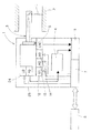
図1は、本発明の表面検査装置の一形態の概略図である。なお、本形態では、以下、被検査物として円筒体の内面を検査する表面検査装置について説明するが、本発明はこれに限定されず、平面状の被検査物の表面を検査するものであってもよい。図示したように、本発明の表面検査装置1は、被検査物である円筒体2の内部に挿入され、円筒体2の内面に光Lを投光しつつその反射光を受光する検査部3と、受光した光を非線形に増幅する非線形増幅器手段である非線形増幅器4と、その非線形増幅部4から送られる信号を、クロック信号発生手段であるエンコーダ5からのサンプリングクロック信号によりA/D変換するA/D変換手段であるA/D変換器6と、検査部3及びA/D変換器6に対する各種制御を行う制御部7と、それらの各種制御及びその他の後述する処理を行う演算処理部8と、を備える。
FIG. 1 is a schematic view of one embodiment of the surface inspection apparatus of the present invention. In the present embodiment, a surface inspection apparatus for inspecting the inner surface of a cylindrical body as an inspection object will be described below. However, the present invention is not limited to this, and the surface of a planar inspection object is inspected. May be. As shown in the drawing, a
図2は検査部3の概略構成を示した図である。図示したように、検査部3は、光源であるレーザダイオード(以下、LDと表記する)24と、受光した光を光電変換して受光量に応じた電圧を発生するフォトディテクタ(以下、PDと表記する)25と、LD24から及びPD25へ光を伝達するセンサヘッド10と、センサヘッド10の外部を囲む外筒11と、外筒11を回転させる回転手段である回転機構12と、外筒11を進退移動させる直線移動手段である直線移動機構13と、回転に合わせてサンプリングクロック信号を発生するエンコーダ5と、センサヘッド10を移動させて光の焦点合わせを行うセンサヘッド調整機構14と、を備える。
FIG. 2 is a diagram showing a schematic configuration of the
センサヘッド10は、投光ファイバ20及び受光ファイバ21と、それらの投光ファイバ20及び複数の受光ファイバ21を保持する保持筒22と、保持筒22の先端に取り付けられ、投光ファイバ20からの光を外部に対して集光し、外部からの光を内部に対して集光する凸レンズ23とを備える。そして投光ファイバ20の基端はLD24に接続され、受光ファイバ20の基端はPD25に接続されている。そしてLD24で発生された光は投光ファイバ20を介して凸レンズ23へ投光され、凸レンズ23から入射した光は受光ファイバ21を介してPD25に伝達される。
The
図3(a)は投光ファイバ20と受光ファイバ21との保持筒22内での断面図を示したものである。図示したように、一本の投光ファイバ20の周りに4本の受光ファイバ21が配置され、また投光ファイバ20の径に比べて受光ファイバ21の径が大きいため、投光面積に比べて受光面積が大きい。なお、投光ファイバの周り配置する受光ファイバの数は4本に限定されず、複数であれば良く、例えば図3(b)に示したように、一本の投光ファイバの周りに3本の受光ファイバを配置することもできる。
FIG. 3A shows a cross-sectional view of the
図2に戻り、センサヘッド10の外側を覆う外筒11は、センサヘッド10と同軸に配置され、その先端の側部には光を通すための投/受光部30が開口されている。また、外筒11内部の先端部には反射鏡31が当該外筒11の軸線Cに対して45度の角度で取り付けられている。この反射鏡31により、センサヘッド10の凸レンズ23を通った光は直角に曲げられ、投/受光部30を通って円筒体2の内面の検査領域Rに投光されるようになっている。また検査領域Rからの反射光も投/受光部30を通って反射鏡31によって直角に曲げられ凸レンズ23を通って受光ファイバ21へ伝達される。
Returning to FIG. 2, the
一方、外筒11の基端側に取り付けられた回転機構12は回転モータを含んでおり、この回転機構12によって外筒11が回転されると、その外筒11に固定された反射鏡31も共に回転し、検査領域Rの位置が円筒体2の内面の周方向に沿って回転する。そして、外筒11が一回転すると、検査領域Rは円筒体2の内面を一周し、その回転に合わせて、エンコーダ5からサンプリングクロック信号が発生される。
On the other hand, the
また、検査部3には、リニアモータ等の直線移動機構13が取り付けられており、外筒11が円筒体2の軸方向Cに沿って進退移動することができるようになっている。これにより、投/受光部30からの光は円筒体2の内面を周方向に沿って走査すると共に軸方向にも相対的に移動し、円筒体2の内面の全体を広範囲で検査することができる。
In addition, a
図1に戻り、受光ファイバ21から伝達された光は、PD25により光電変換され、受光量に応じた電圧に変換される。そしてPD25に接続されている非線形増幅器4は、PD25からの電圧を非線形に増幅するものであり、ログアンプ(図示せず)を有し、ここで、電圧の低い部分が大きく増幅され、電圧の高い部分は小さく増幅される。
Returning to FIG. 1, the light transmitted from the
なお、この非線形増幅器4の次に、高速フーリエ変換装置、ローパスフィルタ及び逆フーリエ変換装置を配置することもできる。あるいは、非線形増幅器4の次にローパスフィルタのみ配置することもできる。これによると、高周波領域に多く表れる表面の荒れや汚れによる光の散乱の影響や、他のノイズの影響を排除することができる。例えば、高速フーリエ変換装置、ローパスフィルタ及び逆フーリエ変換装置を配置した場合、一周の検査時間20msとしたときに、その1/100である0.2ms、周波数にして5000Hz以上をローパスフィルタでカットすると効果的である。
Note that a fast Fourier transform device, a low-pass filter, and an inverse Fourier transform device can be arranged next to the
非線形増幅器4は直接、又は高速フーリエ変換装置、ローパスフィルタ及び逆フーリエ変換装置、若しくはローパスフィルタを介在させて、更にA/D変換器6に接続され、このA/D変換期で信号は、エンコーダ5から発生されるサンプリングクロックに従ってサンプリングされてA/D変換される。サンプリングされたデジタル信号は、制御部7を介して後述する演算処理部8の記憶装置に記録される。なお、制御部7は、LD24、回転機構12、直線移動機構13、センサヘッド調整機構14の制御も行う。
The
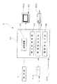
図4は制御部7と接続されている演算処理部8の構成図を示したものである。図示したように、この演算処理部8は、演算装置40と、演算装置40に対する入力装置41としてのキーボード41a及びマウス41bと、必要に応じて出力装置42としてのモニタ42a及びプリンタ42bとを備えている。また、演算装置40は、例えばマイクロプロセッサ及びその動作に必要な記憶装置43(RAM及びROM)等の周辺装置を備えたコンピュータユニットで構成される、例えばパーソナルコンピュータを使用することができる。
FIG. 4 shows a configuration diagram of the
この演算装置40は、円筒体2の内面の周方向の位置をx座標とし、円筒体2の内面の長手方向位置をy座標とした二次元平面において、上述したように回転移動に合わせてサンプリングされて記憶装置43に記憶された受光量に相当するデジタル信号を画素の輝度の強弱として表す表示制御手段44を更に備える。また、その表示された二次元画像を2値化及びエッジ処理等する画像処理手段45も備えている。
The
更に、この演算装置40は、円筒体2の内面に設けられた溝の幅を求めるための溝幅決定手段46も備える。この溝幅決定手段46は、受光量を画素の輝度の強度で表した二次元画像を2値化し、その画像を更にエッジ処理した画像を、y方向に延びる直線に沿って複数に分割し、分割区間毎に溝幅を決定するものである。なお、本形態においてはエッジ処理した画像を分割するが、これに限定されず、受光量をその強度で表した二次元画像又は、それを2値化した画像を分割してもよい。
Further, the
図5は、溝幅決定手段46が分割区間毎に溝幅を決定するアルゴリズムを示したフローチャートである。このフローチャートでは、まずステップ1において、作業者が入力装置41から入力する分割数等の指示に基づいて二次元画像平面をy方向に延びる直線に沿って複数に分割する。ステップ2では一の分割区間内において、x軸座標を一点に固定し、y軸に沿って溝の一方から溝に向って移動し、画素の輝度が隣接画素間で特定の閾値を超えて変化する一点を検索し、そのときのy座標を溝の一側縁部に対応するy座標として記憶する。ステップ3では、同じx軸座標上において、y軸に沿って溝の他方から溝に向って移動し、受光量に相当する画素の輝度が隣接画素間で特定の閾値を超えて変化する他点を検索し、そのときのy座標を溝の他側縁部に対応するy座標として記憶する。ステップ4において、予め作業者によって設定された、一の分割区間内で検索すべきx座標の数だけ両側縁部のy座標を求めたか検討する。そして、まだ所定の数、求めていない場合は、ステップ5に進み、同一の分割区間内でx座標を移動して、またステップ2に戻る。そしてステップ2からステップ4に至る動作を繰り返す。所定の数のx座標についてそれぞれ両側縁部のy座標を求めたら次のステップ6へと進む。ステップ6では、ステップ2で記憶した複数の一側縁部のy座標を集計し、そのうちの、集計数が最も多いy座標を一側縁部の代表座標とする。ステップ7では、同様にステップ3で記憶した複数の他側縁部のy座標を集計し、そのうちの集計数が最も多いy座標の他側縁部の代表座標とする。ステップ8において、その一側縁部の代表座標と他側縁部の代表座標の差を求め、その差をその分割区間における代表的な溝幅として記憶する。ステップ9において全分割区間について代表的な溝幅を決定したか検討し、全分割区間について決定されていない場合は、ステップ10により分割区間を移動して再度のステップ2に戻り、同様の作業を行う。全分割区間について代表的な溝幅を決定すると、フローチャートは終了する。そしてその計算結果は適宜モニタ等の出力装置から出力される。
FIG. 5 is a flowchart showing an algorithm in which the groove
次に、本形態の表面検査装置で、自動車のエンジンのシリンダヘッドの、内面に形成された凹部の側面とその凹部に取り付けられたリング状のバルブシートの側面との隙間の幅を検査し、その幅を測定する場合について説明する。 Next, in the surface inspection apparatus of the present embodiment, the width of the gap between the side surface of the recess formed on the inner surface of the cylinder head of the engine of the automobile and the side surface of the ring-shaped valve seat attached to the recess is inspected, A case where the width is measured will be described.
図6(a)は自動車のエンジンのシリンダヘッドの概略図である。エンジンのシリンダヘッド2は、通常アルミニウム合金等で製造されており、燃焼室内に吸入空気を供給するための吸気ポート101と、燃焼後の排気ガスを排出するための排気ポート102とが形成されている。各ポート101,102は、それぞれバルブ103によって開閉されるようになっており、また各ポート101,102の先端には、凹部104が設けられ、この凹部104には、バルブの気密性と耐久性を確保するために、鉄系の焼結材料等で作られたリング状のバルブシート105が嵌め込まれている。このバルブシート105と凹部104とは隙間なく嵌合されていることが望ましいが、製造上の誤差等によって、実際には多少の隙間Gが発生する。そして、この隙間Gが大きくなると所望のエンジン性能を得ることができないため、この隙間Gの幅を正確に測定し、一定の値以上の隙間を有する不良品は排除することが必要である。このような隙間Gは、図示したようにシリンダヘッド2の内面に存在し、直接目視することができない。このため、従来は、作業者が手作業により隙間Gに薄板材からなるシムを差し込み、シムが入ればその厚さの隙間Gが存在すると判断する方法が広く用いられている。しかし、この方法は、作業者の熟練度の影響が大きく、客観性に欠け、更に、手作業であるため、全品検査が困難であった。
FIG. 6A is a schematic view of a cylinder head of an automobile engine. The
本形態の表面検査装置による、このようなシリンダヘッド2の内面に形成された凹部の側面とその凹部に取り付けられたリング状のバルブシート105の側面との間の幅の検査及びその幅の決定は、以下のように行う。まず、バルブ103が取り付けられていない状態で、吸気ポート101又は排気ポート102のいずれか検査を行うポート内に、シリンダヘッド2の軸線と外筒11の軸線Cとを一致させて、投/受光部30がバルブシートの位置105にくるようにして表面検査装置1の外筒11を配置する。なお、図6(b)は吸気ポート101に表面検査装置1を挿入する場合を示した。次に、図2に示したセンサヘッド調整機構14によってセンサヘッド10を移動させ、シリンダヘッド2の内面に光Lの焦点を合わせる。これにより、LD24からの光は、投光ファイバ20を通って、凸レンズ23により集光されて反射鏡31に到り、直角に光路が変更されて投/受光部30からバルブシート105の内面の検査領域Rに投光される。
Inspection of the width between the side surface of the recess formed on the inner surface of the
この状態で、回転機構12及び直線移動機構13を駆動させると、シリンダヘッド2の内面に投光ファイバ20からの光が順次投光されて、内面の全周から反射光が受光ファイバ21に受光される。そして外筒11は回転し且つ軸方向Cに進み、バルブシート105の内面からシリンダヘッド2の内面にわたる所定範囲内の検査が可能になる。
When the
反射された光Lは投/受光部30を通って反射鏡31で直角に曲げられて、凸レンズ23で集光され、受光ファイバ21に受光される。この場合、シリンダヘッド2の表面は比較的滑らかであるため、投光ファイバ20から投光された光の大部分が正反射して受光ファイバ21によって受光される。バルブシート105の表面は、シリンダヘッド2の内面と比較すると表面がざらついているため、投光ファイバ20を細くして照射スポット径を小さくすると光の散乱の影響が出てくる。溝Gの部分においては、光の散乱がバルブシート105の部分より更に大きく、光の正反射もほとんどない。
The reflected light L passes through the light projecting / receiving
ここで、投光ファイバ20の周囲に受光ファイバ21を4つ配置し且つ受光ファイバ21の径を投光ファイバ20より大きくすることにより受光面積が拡大されている。このため、バルブシート105の部分から受光ファイバ21によって受光される光の量は増加するが、一方、溝の部分から受光される光の量はあまり増加しない。従って、バルブシートの表面の部分と溝の部分との差が明確になる。
Here, the light receiving area is expanded by arranging four
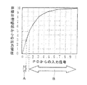
次に、シリンダヘッド2の内面を螺旋状にスキャンしながら受光ファイバ21を介して得られた上述の信号をPD25によって光電変換して受光量に応じた電圧に変換し、非線形増幅器4によって増幅する。図7はPD25からの非線形増幅器4に入力される信号と、非線形増幅器4のログアンプによって非線形に増幅した後の出力電圧の関係を示したグラフである。図7のAで示した部分は、溝の部分のPD25からの信号の部分である。一方、図7のBで示した部分は、バルブシート部分のPD25からの信号を含む、溝部以外の信号の部分である。ここで、PD25からの入力信号における溝からの信号部分Aとそれ以外の信号部分Bとは、上述のように受光ファイバ21の受光面積を大きくすることで、ある程度の差を生じているが、更にこの差を拡大できれば、より明確に両者を区別することができる。一方、この差の部分は、入力信号全体のうちの信号の少ない位置に存在している。従って、PDからの入力信号を非直線アンプあるいはログアンプで対数的に増幅することにより、この差の部分が拡大され、両者の間の出力電圧の差が大きくなり、表面の溝や傷を表面の荒れや汚れから更に区別しやすくなる。また、ログアンプの後に高速フーリエ変換装置、ローパスフィルタ及び逆フーリエ変換装置、あるいは、ローパスフィルタが配置されている場合、高周波領域に多く表れる表面の荒れや汚れによる光の散乱の影響や、他のノイズの影響が排除される。
Next, while the inner surface of the
この出力電圧を、A/D変換器6にて、エンコーダ5から発生されるサンプリングクロックに従ってサンプリングしてA/D変換する。そして演算処理部8の表示制御手段44によって、シリンダヘッド2の周方向をx軸とし、軸方向をy軸とした、格子状の画像データに変換することにより、シリンダヘッド2の内面を展開したような二次元画像を得ることができる。ここで、回転機構に取り付けられたエンコーダから直接サンプリングクロック信号を発生させるので、光の回転と受光データとを同期させることができ、二次元画像が回転むらの影響を受けにくい。
This output voltage is sampled and A / D converted by the A /
図8は、エアシリンダの内面のバルブシートが取り付けられた部分を本発明の表面検査装置1で検査した二次元画像である。図中Aはシリンダヘッド2の内面であり、表面は比較的滑らかであるため反射光量が多く白くなっている。また、図中Bはバルブシート105の内面であり、この部分はシリンダヘッド2の内面と比較すると表面がざらついているため、反射光量が少なく、黒っぽくなっている。そして図中Gは、シリンダヘッド2とバルブシート105との間の隙間であり、この部分からの反射光はほとんどないため、黒くなっている。なお、図示しないが、受光ファイバの数が複数でなく且つ増幅器も線形である従来の表面検査装置の場合、同様の二次元画像において、シリンダヘッド2の内面は真っ白であり、バルブシート105と溝の部分は共に真っ黒となり、両者を区別することはできない。しかし、本形態の表面検査装置によると、図8で示したように、バルブシートの部分Bと、溝の部分Gとの間には、明暗に差が生じ、両者を区別することが可能となる。
FIG. 8 is a two-dimensional image obtained by inspecting the portion of the inner surface of the air cylinder where the valve seat is attached with the
より明確に溝Gを特定するために、図8の画像の画素の明るさを算出し、溝Gの部分の輝度とバルブシートBの部分の輝度との間に閾値を設定し、画素の明るさが閾値以上なら白色を画素に設定し、閾値以下の場合は、画素に黒色を設定する2値化処理を行う。この処理によって得られた画像が図9であり、溝Gを明確に特定することができる。更にその画像をエッジ処理し、溝Gの一側縁部g1と他側縁部g2とを黒点で表示したものが図10である。なお、この2値化処理及びエッジ処理は任意であって、これらの処理を行わずに、上述のように図5のデータから直接、溝Gの縁部の座標を求めることもできる。 In order to specify the groove G more clearly, the brightness of the pixel in the image of FIG. 8 is calculated, a threshold is set between the brightness of the groove G and the brightness of the valve seat B, and the brightness of the pixel If the threshold value is equal to or greater than the threshold value, white is set for the pixel, and if the threshold value is equal to or less than the threshold value, binarization processing is performed for setting the pixel to black. An image obtained by this processing is shown in FIG. 9, and the groove G can be clearly identified. Further, the image is edge-processed, and one side edge g1 and the other side edge g2 of the groove G are displayed with black dots as shown in FIG. The binarization process and the edge process are optional, and the coordinates of the edge of the groove G can be obtained directly from the data shown in FIG. 5 without performing these processes.
次に、この画像を、図10で示したようにx軸に沿って均等に1〜10の区間に分割する(S1)。そして、第1区間Z内において、x座標を一点に固定し、y座標に沿って、図中y座標aの位置から溝に向って一側縁部g1に相当する黒点を検索し、その点のy座標を求めて記憶する(S2)。次に、図中y座標bの位置から溝に向って他側縁部g2に相当する黒点を検索し、その点のy座標を求めて記憶する(S2)。この場合、y座標上に、ノイズ等の影響から溝の縁部に対応しない点も存在するが、適宜排除する。
Next, this image is equally divided into
そして第1区間Z内において、所定数の両側縁部のy座標を求め(S4,S5)検索された複数の一点のy座標のうちの、最も多くの点が占めた座標を一側縁部の代表座標とする(S6)。同様に検索された複数の他点のy座標のうちの、最も多くの点が占めた座標の他側縁部の代表座標とする(S7)。次いで一側縁部の代表座標と他側縁部の代表座標との差を求め、その値を第1区間の代表溝幅とする(S8)。更に、第2区間から第10区間第1区間までについても同様の計算を行い(S9,S10)、区間毎の代表幅を求める。以上、本形態の溝幅決定手段46によると、自動的且つ客観的に溝Gの区間毎の代表幅を決定することができる。
Then, in the first section Z, the y coordinate of a predetermined number of both side edges is obtained (S4, S5), and the coordinates occupied by the most points among the searched y coordinates of one point are set as one side edge. (S6). Similarly, the representative coordinates of the other side edge of the coordinates occupied by the most points among the y coordinates of a plurality of other points searched are used (S7). Next, the difference between the representative coordinates of the one side edge and the representative coordinates of the other side edge is obtained, and the value is set as the representative groove width of the first section (S8). Further, the same calculation is performed for the second section to the tenth section and the first section (S9, S10), and the representative width for each section is obtained. As described above, according to the groove
なお、例えばバルブシートが斜めに入っている場合等、溝の幅が一定でない場合ある。この場合、周方向全体で溝幅を計算すると、平均的な値となってしまうが、バルブシートの場合等平均値よりも最大溝幅が問題となる場合もある。本形態によると等間隔の複数の領域で分割して計算しているため、溝幅が一定でない場合、分割区間毎に溝幅を求めることができ、最大溝幅及び最小溝幅も求めることができる。またバルブが傾いているか否かを判断することもできる。ただし、本形態はこれに限定さるものではなく、分割をせずに全体についての代表的溝幅を決定することもでき、また、溝の一点における溝幅のみ求めることもできる。 The groove width may not be constant, for example, when the valve seat is inclined. In this case, if the groove width is calculated in the entire circumferential direction, an average value is obtained. However, in the case of a valve seat, the maximum groove width may be more problematic than the average value. According to the present embodiment, since the calculation is performed by dividing into a plurality of equally spaced regions, when the groove width is not constant, the groove width can be obtained for each divided section, and the maximum groove width and the minimum groove width can also be obtained. it can. It can also be determined whether or not the valve is tilted. However, the present embodiment is not limited to this, and it is possible to determine a representative groove width for the whole without dividing, and it is also possible to obtain only the groove width at one point of the groove.
以上、本形態の表面検査装置2によると、受光ファイバ21の受光面積が拡大され、また非線形増幅器を有するため、エンジンのシリンダヘッドの側面と、バルブシートの側面との間の微細な隙間と、バルブシートの表面の荒れや汚れとの差を明確にすることができ、その微細な隙間を明確に検出することが可能となる。従って、本形態の表面検査装置は、自動車部品等の検査基準の厳しい製造ラインに組み込こむことができ、全品検査も可能となり、製品精度、品質及びスループットの向上が可能となる。
As described above, according to the
なお、本発明の好適な形態について説明したが、本発明は、上述した形態に限定されることなく、種々の形態にて実施してよい。例えば、上述したように、本形態では、被検査物として円筒体の内面を検査する表面検査装置について説明したが、これに限定されず、平面状の被検査物の表面を検査するものであってもよい。 In addition, although the suitable form of this invention was demonstrated, this invention may be implemented with a various form, without being limited to the form mentioned above. For example, as described above, in the present embodiment, the surface inspection apparatus that inspects the inner surface of the cylindrical body as the object to be inspected has been described. However, the present invention is not limited thereto, and the surface inspection apparatus inspects the surface of the planar object to be inspected. May be.
1 表面検査装置
2 被検査物(円筒体,シリンダヘッド)
4 非線形増幅器(非線形増幅手段)
5 エンコーダ(クロック信号発生手段)
6 A/D変換部
12 回転機構(回転手段)
13 直線移動機構(直線移動手段)
20 投光ファイバ
21 受光ファイバ
30 投/受光部
46 溝幅決定手段
C 軸線
G 溝
L 光
g1 一点
g2 他点
1
4 Non-linear amplifier (non-linear amplification means)
5 Encoder (clock signal generation means)
6 A /
13 Linear movement mechanism (linear movement means)
20 Emitting
Claims (6)
前記投光ファイバの周囲に前記受光ファイバが複数配置され、且つ前記受光ファイバの径が前記投光ファイバの径よりも大きいことを特徴とする表面検査装置。 In a surface inspection apparatus that receives reflected light of a light projected from a light source through a projection fiber onto a surface of the inspection object through a light receiving fiber and inspects the surface of the inspection object based on the amount of the received light ,
A surface inspection apparatus in which a plurality of the light receiving fibers are arranged around the light projecting fiber, and a diameter of the light receiving fiber is larger than a diameter of the light projecting fiber.
The object to be inspected is an engine cylinder head, and the surface of the object to be inspected is an inner surface of the cylinder head, and the grooves and scratches are fitted into the side surface of the recess provided on the inner surface and the recess. The surface inspection apparatus according to claim 1, wherein the surface inspection apparatus has a gap with a side surface of the valve seat.
Priority Applications (3)
| Application Number | Priority Date | Filing Date | Title |
|---|---|---|---|
| JP2005338860A JP2007147324A (en) | 2005-11-24 | 2005-11-24 | Surface inspection device |
| PCT/JP2006/322814 WO2007060873A1 (en) | 2005-11-24 | 2006-11-16 | Surface examination device |
| US11/561,950 US20070132990A1 (en) | 2005-11-24 | 2006-11-21 | Surface inspection apparatus |
Applications Claiming Priority (1)
| Application Number | Priority Date | Filing Date | Title |
|---|---|---|---|
| JP2005338860A JP2007147324A (en) | 2005-11-24 | 2005-11-24 | Surface inspection device |
Publications (1)
| Publication Number | Publication Date |
|---|---|
| JP2007147324A true JP2007147324A (en) | 2007-06-14 |
Family
ID=38208910
Family Applications (1)
| Application Number | Title | Priority Date | Filing Date |
|---|---|---|---|
| JP2005338860A Pending JP2007147324A (en) | 2005-11-24 | 2005-11-24 | Surface inspection device |
Country Status (1)
| Country | Link |
|---|---|
| JP (1) | JP2007147324A (en) |
Cited By (4)
| Publication number | Priority date | Publication date | Assignee | Title |
|---|---|---|---|---|
| JP2011008020A (en) * | 2009-06-25 | 2011-01-13 | Toyota Motor Corp | Probe for inspection of hole inside and inspection device |
| JP2012078133A (en) * | 2010-09-30 | 2012-04-19 | Kirin Techno-System Co Ltd | Inspection head of surface inspection device |
| WO2013121831A1 (en) * | 2012-02-17 | 2013-08-22 | 株式会社日立製作所 | Very small signal detecting method and system |
| WO2020235578A1 (en) * | 2019-05-23 | 2020-11-26 | 長野オートメーション株式会社 | Inspection system |
Citations (5)
| Publication number | Priority date | Publication date | Assignee | Title |
|---|---|---|---|---|
| JPS51106488A (en) * | 1975-03-14 | 1976-09-21 | Aisin Seiki | HIKENTAINONAIMENKENSAHOHOTO SONOSOCHI |
| JPH01250806A (en) * | 1988-03-31 | 1989-10-05 | Nachi Fujikoshi Corp | Method and device for measuring width |
| JPH04199505A (en) * | 1990-11-29 | 1992-07-20 | Canon Inc | Alignment apparatus |
| JPH0979993A (en) * | 1995-09-08 | 1997-03-28 | Advantest Corp | Inspection method by image processing |
| JPH11281582A (en) * | 1998-03-26 | 1999-10-15 | Tb Optical Kk | Surface inspection apparatus |
-
2005
- 2005-11-24 JP JP2005338860A patent/JP2007147324A/en active Pending
Patent Citations (5)
| Publication number | Priority date | Publication date | Assignee | Title |
|---|---|---|---|---|
| JPS51106488A (en) * | 1975-03-14 | 1976-09-21 | Aisin Seiki | HIKENTAINONAIMENKENSAHOHOTO SONOSOCHI |
| JPH01250806A (en) * | 1988-03-31 | 1989-10-05 | Nachi Fujikoshi Corp | Method and device for measuring width |
| JPH04199505A (en) * | 1990-11-29 | 1992-07-20 | Canon Inc | Alignment apparatus |
| JPH0979993A (en) * | 1995-09-08 | 1997-03-28 | Advantest Corp | Inspection method by image processing |
| JPH11281582A (en) * | 1998-03-26 | 1999-10-15 | Tb Optical Kk | Surface inspection apparatus |
Cited By (6)
| Publication number | Priority date | Publication date | Assignee | Title |
|---|---|---|---|---|
| JP2011008020A (en) * | 2009-06-25 | 2011-01-13 | Toyota Motor Corp | Probe for inspection of hole inside and inspection device |
| JP2012078133A (en) * | 2010-09-30 | 2012-04-19 | Kirin Techno-System Co Ltd | Inspection head of surface inspection device |
| WO2013121831A1 (en) * | 2012-02-17 | 2013-08-22 | 株式会社日立製作所 | Very small signal detecting method and system |
| JPWO2013121831A1 (en) * | 2012-02-17 | 2015-05-11 | 株式会社日立製作所 | Minute signal detection method and system |
| WO2020235578A1 (en) * | 2019-05-23 | 2020-11-26 | 長野オートメーション株式会社 | Inspection system |
| JPWO2020235578A1 (en) * | 2019-05-23 | 2021-10-21 | 長野オートメーション株式会社 | Inspection system |
Similar Documents
| Publication | Publication Date | Title |
|---|---|---|
| US20070132990A1 (en) | Surface inspection apparatus | |
| US11105754B2 (en) | Multi-parameter inspection apparatus for monitoring of manufacturing parts | |
| US7791721B2 (en) | Surface inspection with variable digital filtering | |
| JP2009139248A (en) | Defect detecting optical system and surface defect inspecting device for mounting defect detecting image processing | |
| US7456948B2 (en) | Method for detecting particles and defects and inspection equipment thereof | |
| US8563958B2 (en) | Inspection apparatus and inspection method | |
| TW201305531A (en) | Pattern measurement apparatus and pattern measurement method | |
| JP2003329606A (en) | Inner surface inspection device | |
| JP2007147324A (en) | Surface inspection device | |
| JP5564807B2 (en) | Defect inspection apparatus and defect inspection method | |
| JP2007147323A (en) | Surface inspection device | |
| US7692781B2 (en) | Glazing inspection | |
| JP4597946B2 (en) | End tilt angle measuring method, inspection method and inspection apparatus for inspected object having undulations | |
| WO2004072628A1 (en) | Defect inspection device and method therefor | |
| JP2007333608A (en) | Inspection device and inspection method of irregular flaw on sheet | |
| JP5278783B1 (en) | Defect inspection apparatus, defect inspection method, and defect inspection program | |
| JP2008057983A (en) | Device and method for evaluating lens polishing precision | |
| JP5367292B2 (en) | Surface inspection apparatus and surface inspection method | |
| CN111640085B (en) | Image processing method and apparatus, detection method and apparatus, and storage medium | |
| JP2011209092A (en) | Round rod inspection apparatus and method of inspecting round rod | |
| JP2006003168A (en) | Measurement method for surface shape and device therefor | |
| JP2003247954A (en) | Defect detection method for round body circumference | |
| CN111316090A (en) | Microscopic defect detection system and method for transparent or semitransparent material | |
| JP2004132900A (en) | Evaluation device for inner circumferential face of engine bore | |
| JP2008185356A (en) | Round rod inspection device and round rod inspection method |
Legal Events
| Date | Code | Title | Description |
|---|---|---|---|
| A621 | Written request for application examination |
Free format text: JAPANESE INTERMEDIATE CODE: A621 Effective date: 20081120 |
|
| A521 | Written amendment |
Free format text: JAPANESE INTERMEDIATE CODE: A523 Effective date: 20090116 |
|
| A521 | Written amendment |
Free format text: JAPANESE INTERMEDIATE CODE: A523 Effective date: 20090309 |
|
| A711 | Notification of change in applicant |
Effective date: 20090416 Free format text: JAPANESE INTERMEDIATE CODE: A712 |
|
| A521 | Written amendment |
Effective date: 20090416 Free format text: JAPANESE INTERMEDIATE CODE: A821 |
|
| A131 | Notification of reasons for refusal |
Free format text: JAPANESE INTERMEDIATE CODE: A131 Effective date: 20110802 |
|
| A02 | Decision of refusal |
Effective date: 20111206 Free format text: JAPANESE INTERMEDIATE CODE: A02 |