JP2007144871A - Multicolor molded product and its molding method - Google Patents
Multicolor molded product and its molding method Download PDFInfo
- Publication number
- JP2007144871A JP2007144871A JP2005344220A JP2005344220A JP2007144871A JP 2007144871 A JP2007144871 A JP 2007144871A JP 2005344220 A JP2005344220 A JP 2005344220A JP 2005344220 A JP2005344220 A JP 2005344220A JP 2007144871 A JP2007144871 A JP 2007144871A
- Authority
- JP
- Japan
- Prior art keywords
- molding
- door trim
- resin
- cavity
- dividing bar
- Prior art date
- Legal status (The legal status is an assumption and is not a legal conclusion. Google has not performed a legal analysis and makes no representation as to the accuracy of the status listed.)
- Pending
Links
Images


Abstract
Description
この発明は、ドアトリム、リヤパーセルシェルフ、フロアトリム、トランクトリム、ラゲージトリム、ルーフトリム、リヤサイドトリム等の自動車用内装部品に好適な多色成形品及びその成形方法に係り、特に、境界溝部付近の外観性能を高めることができるとともに、成形サイクルを短縮化できる多色成形品及びその成形方法に関する。 The present invention relates to a multicolor molded product suitable for automotive interior parts such as door trims, rear parcel shelves, floor trims, trunk trims, luggage trims, roof trims, rear side trims, and the like, and in particular, the molding method thereof. The present invention relates to a multicolor molded product that can enhance the appearance performance and can shorten the molding cycle, and a molding method thereof.
図12は、上下二分割構造の自動車用ドアトリム1を示す正面図であり、この自動車用ドアトリム1は、ドアトリムアッパー2とドアトリムロア3との上下二分割体から構成され、ドアトリムアッパー2とドアトリムロア3との接合部位には、境界溝部4が設定されている。次いで、上記ドアトリム1を成形する成形金型5の構成について、図13を基に説明する。成形金型5は、所定ストローク上下動可能な成形上型6と、その下方に位置する固定側の成形下型7と、成形下型7に接続され、溶融樹脂を供給する射出機8a,8bと、ドアトリムアッパー2とドアトリムロア3との境界溝部4に配設され、キャビティを2つの分割されたキャビティC1,C2に区画する分割バー9とから大略構成されている。
FIG. 12 is a front view showing an
そして、この成形金型5を使用して、二色成形品であるドアトリム1を成形する工程について説明する。まず、成形上型6を下降操作し、成形上下型6,7を型締めする。この時、図14(a),(b)に示すように、分割バー9はシリンダ9aの伸長動作により、上方に位置してドアトリムアッパー2を成形するためのキャビティC1とドアトリムロア3を成形するためのキャビティC2とを区画しており、第1の射出機8aから溶融樹脂M1がキャビティC1に射出充填される。尚、キャビティC1には、ドアトリムアッパー2の表皮2aが予めセットされており、表皮2aと樹脂成形品2bとの積層体からなるドアトリムアッパー2が成形される。
And the process of shape | molding the
その後、シリンダ9aが収縮動作を行ない、図15(a),(b)に示すように、分割バー9が下降した後、第2の射出機8bから溶融樹脂M2がキャビティC2に射出充填され、更にこの溶融樹脂M2は、分割バー9が下降して生じるスペース内にも充填されてドアトリムアッパー2と一体化する形でドアトリムロア3が所要形状に成形されて、二色成形品であるドアトリム1の成形が完了する。上述したドアトリム1のような二色成形品の成形方法及び成形金型については、特許文献1に詳細に記載されている。
Thereafter, the
このように、従来では、上下二分割構造の自動車用ドアトリム1のような多色成形品を同一の成形金型5を使用して成形する場合には、成形金型5内に内装される分割バー9を上下駆動させて行なっていたが、従来では、例えば、図14(a)に示すドアトリムアッパー2の成形時、分割バー9と成形上型6との間の接触強度が適切に維持されていない場合は、図16に示すように、溶融樹脂M1がキャビティC2側に染み出し、外観不良が生じるため、この分割バー9の上下ストローク動作を精度良く管理して、成形上型6に対する接触強度を常に均一に維持する必要があった。そして、そのため、射出圧を低く、かつ時間をかけて成形する必要があり、成形性を低下させる大きな要因となっている。
As described above, conventionally, when a multicolor molded product such as the
この発明は、このような事情に鑑みてなされたもので、成形金型内のキャビティを分割バーにより複数のキャビティに分割して各キャビティにそれぞれ専用の射出機から溶融樹脂を射出充填して成形される多色成形品及びその成形方法であって、分割バー上面の形状又はその周囲の金型面の形状を工夫することで、分割バーの近傍部分における溶融樹脂の流速を低減させることにより、樹脂の染み出しが原因となる成形不良を確実に防止でき、かつ成形サイクルの短縮化を可能とした多色成形品及びその成形方法を提供することを目的とする。 The present invention has been made in view of such circumstances. The cavity in the molding die is divided into a plurality of cavities by a dividing bar, and each cavity is injected and filled with a molten resin from a dedicated injection machine. Multi-color molded product and its molding method, by devising the shape of the upper surface of the split bar or the shape of the mold surface around it, by reducing the flow rate of the molten resin in the vicinity of the split bar, It is an object of the present invention to provide a multicolor molded product and a molding method thereof that can reliably prevent molding defects caused by resin seepage and can shorten the molding cycle.
上記課題を解決するために、本発明は、成形金型のキャビティを分割バーにより複数のキャビティに区画し、各キャビティ内に対応する射出機から溶融樹脂を上記各キャビティ内に射出充填して、分割バーに対応する境界溝部を基に複数の樹脂成形品を一体化してなる多色成形品において、前記分割バーの上面及び分割バー近傍の成形下型型面の少なくとも一方側には凹凸加工部が刻設されていることで、上記多色成形品の境界溝部近傍部分は、一般部分と同一厚みの基準厚みに加えて厚みの凹凸層が一体化されていることを特徴とする。 In order to solve the above problems, the present invention divides a cavity of a molding die into a plurality of cavities by a dividing bar, and injects and fills molten resin into the cavities from an injection machine corresponding to the cavities. In a multicolor molded product obtained by integrating a plurality of resin molded products based on the boundary groove corresponding to the dividing bar, an unevenness processing portion is provided on at least one side of the upper surface of the dividing bar and the molding lower mold surface in the vicinity of the dividing bar. Is formed, and in the vicinity of the boundary groove portion of the multicolor molded product, an uneven layer having a thickness is integrated in addition to the reference thickness having the same thickness as the general portion.
ここで、多色成形品とは、単一の成形金型に少なくとも2つ以上の複数の異なるキャビティを設定し、各キャビティに異種材料の溶融樹脂を射出充填することで、外観の異なる複数の樹脂成形品を接合一体化して成形される二色成形品、三色成形品等のことをいう。尚、一方側の樹脂成形品の表面には、表皮を積層一体化することもできる。この多色成形品の用途としては、例えば、ドアトリム、リヤパーセルシェルフ、フロアトリム、トランクトリム、ラゲージトリム、ルーフトリム、リヤサイドトリム等の自動車用内装部品全般に適用できる。 Here, the multi-color molded product is a plurality of different cavities set in at least two or more in a single molding die, and a plurality of different appearances are injected and filled in each cavity by a molten resin of different materials. It refers to a two-color molded product, a three-color molded product, etc. that are molded by joining and molding resin molded products. A skin can be laminated and integrated on the surface of the resin molded product on one side. For example, the multicolor molded product can be applied to automotive interior parts such as door trims, rear parcel shelves, floor trims, trunk trims, luggage trims, roof trims, rear side trims, and the like.
上記樹脂成形品の材料としては、1種類の熱可塑性樹脂でも、2種類以上の熱可塑性樹脂から構成しても良い。好ましくは、ポリエチレン系樹脂、ポリプロピレン系樹脂、ポリスチレン系樹脂、ポリエチレンテレフタレート系樹脂、ポリビニルアルコール系樹脂、塩化ビニル系樹脂、ポリアミド系樹脂、ポリアセタール系樹脂、ポリカーボネート系樹脂、アイオノマー系樹脂、アクリロニトリル/ブタジエン/スチレン(ABS)樹脂等が使用でき、これらの熱可塑性樹脂中に各種充填剤を混入しても良い。使用できる充填剤としては、ガラス繊維、カーボン繊維等の無機繊維、タルク、クレイ、シリカ、炭酸カルシウム等の無機粒子がある。また、酸化防止剤、紫外線吸収剤、着色剤、難燃剤、低収縮剤等の各種の添加剤が配合されても良い。 The material of the resin molded product may be one kind of thermoplastic resin or two or more kinds of thermoplastic resins. Preferably, polyethylene resin, polypropylene resin, polystyrene resin, polyethylene terephthalate resin, polyvinyl alcohol resin, vinyl chloride resin, polyamide resin, polyacetal resin, polycarbonate resin, ionomer resin, acrylonitrile / butadiene / Styrene (ABS) resin or the like can be used, and various fillers may be mixed in these thermoplastic resins. Examples of the filler that can be used include inorganic fibers such as glass fiber and carbon fiber, and inorganic particles such as talc, clay, silica, and calcium carbonate. Moreover, various additives, such as antioxidant, a ultraviolet absorber, a coloring agent, a flame retardant, and a low shrinkage agent, may be mix | blended.
次いで、本発明に係る多色成形品の成形方法は、成形金型のキャビティを分割バーにより複数のキャビティに区画し、各キャビティ内に対応する射出機から溶融樹脂を上記各キャビティ内に射出充填して、分割バーに対応する境界溝部を基に複数の樹脂成形品を一体化してなる多色成形品の成形方法において、前記成形金型内に内装される分割バーの上面及びその周囲の成形下型の型面の少なくとも一方側は、溶融樹脂の流速を低減させる凹凸加工部が一般面から穿設加工されていることで、一方側のキャビティ内に溶融樹脂を充填する際、あるいは他方側のキャビティ内に溶融樹脂を充填する際、分割バーの近傍部分で溶融樹脂の流速が低減され、射出機の吐出圧を低減できることを特徴とする。 Next, in the method for molding a multicolor molded product according to the present invention, the cavity of the molding die is divided into a plurality of cavities by dividing bars, and molten resin is injected and filled into the cavities from the corresponding injection machines in the cavities. Then, in a molding method of a multicolor molded product in which a plurality of resin molded products are integrated based on the boundary groove corresponding to the dividing bar, the upper surface of the dividing bar incorporated in the molding die and molding around the upper surface At least one side of the mold surface of the lower mold has a concave and convex portion that reduces the flow rate of the molten resin drilled from the general surface, so that when the molten resin is filled into the cavity on one side or on the other side When the molten resin is filled in the cavity, the flow rate of the molten resin is reduced in the vicinity of the dividing bar, and the discharge pressure of the injection machine can be reduced.
ここで、本発明方法に使用する成形金型は、相互に型締め及び型開き可能な成形上下型と、成形下型に内装され、キャビティを分割区画するために上下動可能に設置される分割バーと、各キャビティ内に溶融樹脂を供給する射出機とから構成され、各キャビティ内に溶融樹脂を射出充填する際、分割バー付近での溶融樹脂の流速を低減させるために、分割バーの上面及びその近傍の金型型面の少なくともいずれか一方側に凹凸加工部が設定されている。 Here, the molding die used in the method of the present invention is a molding upper and lower mold that can be clamped and opened with each other, and a split that is installed in the molding lower mold and is installed so as to be movable up and down to divide the cavity. The upper surface of the dividing bar is configured to reduce the flow rate of the molten resin near the dividing bar when the molten resin is injected and filled into each cavity. And the uneven | corrugated processed part is set in at least any one side of the metal mold | die surface of the vicinity.
すなわち、上記成形金型は、分割バーが配置されて複数のキャビティを区画する部分において、溶融樹脂の流速を低減するための手段として、分割バーの上面に溶融樹脂の流速を低減させる形状が設定されているか、あるいは、分割バー付近の金型型面に溶融樹脂の流速を低減させる型面形状が設定されている。例えば、分割バーの上面のみに凹凸加工部を設定するか、金型の型内のみに凹凸加工部を設定するか、分割バーの上面と金型型面の双方に凹凸加工部を設定するかの3つの形態が考えられるが、そのいずれにおいても、基本的に成形上下型の型クリアランスとしては一般部と同等のクリアランスを確保している。更に、分割バーの上面、あるいは金型の型面に凹凸加工部を穿設加工することで、一般部に比べ凹凸加工部分のみクリアランスが大きく保たれている。その結果、溶融樹脂の充填時間も遅くなり、樹脂速度を低減し、それに応じて射出機の吐出圧を低く抑えることができ、他方側のキャビティに樹脂漏れが生じる恐れがない。 In other words, the molding die has a shape that reduces the flow rate of the molten resin on the upper surface of the divided bar as a means for reducing the flow rate of the molten resin at the portion where the divided bars are arranged to partition the plurality of cavities. Alternatively, a mold surface shape for reducing the flow rate of the molten resin is set on the mold surface near the dividing bar. For example, whether to set the concavo-convex portion only on the upper surface of the dividing bar, whether to set the concavo-convex portion only in the mold, or to set the concavo-convex portion on both the upper surface of the dividing bar and the mold surface However, in any of these, basically, the same clearance as that of the general part is secured as the mold clearance of the molded upper and lower molds. Furthermore, by forming a concave and convex portion on the upper surface of the dividing bar or the mold surface of the mold, only the concave and convex portion is kept larger than the general portion. As a result, the filling time of the molten resin is also delayed, the resin speed can be reduced, the discharge pressure of the injection machine can be kept low accordingly, and there is no risk of resin leakage in the other cavity.
従って、本発明に係る多色成形品及びその成形方法によれば、成形上下型が型締めされて、キャビティが画成され、更にキャビティ内に分割バーが上昇して複数のキャビティに分割した後に一方側のキャビティ内に溶融樹脂の射出充填が行なわれるが、この時、分割バーの上面、あるいは分割バーと隣接する金型型面の少なくともいずれか一方には、型クリアランスを確保した基準面に対して凹凸加工部が形成されているため、分割バーに到達する溶融樹脂はその樹脂速度が低減され、他方側のキャビティに染み出すことがなく、樹脂の染み出しによる成形不良を可及的に防止できる。また、分割バー近傍部分の樹脂の速度を低減させることができるため、溶融樹脂の射出圧を高く設定することが可能となり、成形サイクルを短縮化でき、生産性を向上させることができる。 Therefore, according to the multicolor molded product and the molding method thereof according to the present invention, the molding upper and lower molds are clamped to define the cavity, and further, the dividing bar rises in the cavity and is divided into a plurality of cavities. The molten resin is injected and filled into the cavity on one side. At this time, at least one of the upper surface of the dividing bar and the mold surface adjacent to the dividing bar is provided with a reference surface that secures a mold clearance. On the other hand, since the uneven processed part is formed, the resin speed of the molten resin that reaches the dividing bar is reduced, and it does not ooze out to the cavity on the other side, and molding defects due to oozing out of the resin are made as much as possible. Can be prevented. Further, since the speed of the resin in the vicinity of the dividing bar can be reduced, the injection pressure of the molten resin can be set high, the molding cycle can be shortened, and the productivity can be improved.
更に、本発明に係る多色成形品及びその成形方法によれば、分割バーの上面か、あるいは分割バーと隣接する金型の型面のいずれか一方側に凹凸加工部を基準面から穿設加工することにより、一方側のキャビティ内に充填する溶融樹脂と、他方側のキャビティ内に充填する溶融樹脂の接触面積を増大させることができ、接合部分の強度を強化できる。 Furthermore, according to the multicolor molded product and the molding method thereof according to the present invention, the concave and convex portion is formed from the reference surface on either the upper surface of the dividing bar or the mold surface of the mold adjacent to the dividing bar. By processing, the contact area between the molten resin filled in the cavity on one side and the molten resin filled in the cavity on the other side can be increased, and the strength of the joint portion can be enhanced.
以上説明した通り、本発明に係る多色成形品及びその成形方法は、成形金型に配設されている分割バーの昇降動作により、製品キャビティを複数の異なるキャビティに区画するとともに、分割バーの上面及び分割バー周囲の金型型面の少なくとも一方側には、溶融樹脂の流速を低減させる凹凸加工部が形成され、特に基準面に凹凸加工部を穿設加工しているため、樹脂速度を低減することができる。従って、樹脂成形品を成形する際、溶融樹脂が対応するキャビティから外部に染み出すことがなく、成形不良を未然に防止できることから、歩留まりを高めることができるとともに、溶融樹脂の外部への染み出しを確実に防止できるため、射出圧力を比較的高く設定することが可能となり、成形サイクルを短縮化でき、成形性を高めることができるという効果を有する。 As described above, the multicolor molded product and the molding method thereof according to the present invention partition the product cavity into a plurality of different cavities by the lifting and lowering operation of the split bar disposed in the molding die, and On at least one side of the mold surface around the upper surface and the dividing bar, an uneven processing portion for reducing the flow rate of the molten resin is formed, and since the uneven processing portion is drilled especially on the reference surface, the resin speed is increased. Can be reduced. Therefore, when molding a resin molded product, the molten resin does not ooze out from the corresponding cavity, and molding defects can be prevented beforehand, so that the yield can be increased and the molten resin oozes out to the outside. Therefore, the injection pressure can be set relatively high, the molding cycle can be shortened, and the moldability can be improved.
更に、本発明によれば、分割バーの上面か、分割バーと隣接する金型型面のいずれか一方に凹凸加工部を形成することにより、一方側のキャビティ内に充填する溶融樹脂と他方側のキャビティ内に充填する溶融樹脂同士の接着面積が増えるため、接合強度を強化することができるとともに、剛性をアップさせることができるという効果を有する。 Furthermore, according to the present invention, by forming a concavo-convex portion on either the upper surface of the dividing bar or the mold surface adjacent to the dividing bar, the molten resin filled in the cavity on one side and the other side Since the bonding area between the molten resins filled in the cavities increases, the bonding strength can be enhanced and the rigidity can be increased.
以下、本発明に係る多色成形品及びその成形方法の好適な実施例について、上下二分割タイプの自動車用ドアトリム及びその成形方法を例示して説明する。尚、念のため付言すれば、本発明の要旨は特許請求の範囲に記載した通りであり、以下に説明する実施例の内容は、本発明の一例を単に示すものに過ぎない。 Hereinafter, a preferred embodiment of a multicolor molded product and a molding method thereof according to the present invention will be described by exemplifying an upper and lower split type automobile door trim and a molding method thereof. Note that the gist of the present invention is as described in the scope of claims, and the contents of the embodiments described below are merely examples of the present invention.
図1乃至図11は本発明の一実施例を示し、図1はツートンタイプの自動車用ドアトリムを示す正面図、図2は同ドアトリムを裏面側からみた正面図及び境界溝部近傍の製品裏面の拡大図、図3は同ドアトリムの構成を示す断面図、図4乃至図6は同ドアトリムを成形する際に使用する成形金型を示すもので、図4は成形金型の全体図、図5は成形金型における分割バー近傍部分の構成を示す断面図、図6は同分割バーの全体構成を示す説明図、図7乃至図11は同ドアトリムの成形方法における各工程を示す説明図である。 1 to 11 show an embodiment of the present invention, FIG. 1 is a front view showing a two-tone type automobile door trim, and FIG. 2 is a front view of the door trim as seen from the rear side, and an enlarged rear view of a product near a boundary groove. FIG. 3 is a sectional view showing the structure of the door trim, FIGS. 4 to 6 show a molding die used when molding the door trim, FIG. 4 is an overall view of the molding die, and FIG. FIG. 6 is an explanatory view showing the overall structure of the divided bar, and FIGS. 7 to 11 are explanatory views showing the respective steps in the method for forming the door trim.
図1乃至図3において、ツートンタイプの自動車用ドアトリム10は、積層構造体からなるドアトリムアッパー20と樹脂単体品からなるドアトリムロア30との上下二分割体から構成されている。上記ドアトリムアッパー20は、樹脂基材21の表面に表皮22が貼付された積層構造体からなり、ドアトリムロア30は合成樹脂の射出成形体から構成されている。上記ドアトリムアッパー20における樹脂基材21、及びドアトリムロア30の材質としては、1種類の熱可塑性樹脂でも、2種類以上の熱可塑性樹脂の混合材料からなっても良い。好ましくは、ポリエチレン系樹脂、ポリプロピレン系樹脂、ポリスチレン系樹脂、ポリエチレンテレフタレート系樹脂、ポリビニルアルコール系樹脂、塩化ビニル系樹脂、ポリアミド系樹脂、ポリアセタール系樹脂、ポリカーボネート系樹脂、アイオノマー系樹脂、アクリロニトリル/ブタジエン/スチレン(ABS)樹脂等が使用でき、これらの熱可塑性樹脂中に各種充填剤を混入しても良い。使用できる充填剤としては、ガラス繊維、カーボン繊維等の無機繊維、タルク、クレイ、シリカ、炭酸カルシウム等の無機粒子がある。また、酸化防止剤、紫外線吸収剤、着色剤、難燃剤、低収縮剤等の各種の添加剤が配合されても良い。
1 to 3, a two-tone
上記ドアトリム10に装着される機能部品としては、ドアトリムアッパー20にインサイドハンドルユニット11が取り付けられている。一方、ドアトリムロア30には、乗員が肘を掛けて休めるように、アームレスト12が設けられており、このアームレスト12には、図示はしないが、パワーウインドウスイッチエスカッションやドアロックスイッチ等のスイッチユニットが装備されても良い。また、アームレスト12の下方には、備品を収容できるドアポケット開口13が開設されており、ドアポケット開口13のフロント側には、スピーカグリル14がドアトリムロア30と一体、あるいは別体に設けられている。上記ドアトリム10は、図3に示すように、ドアパネル15に対して図示しないクリップ等の固着手段を介して取り付けられており、ドアトリムロア30におけるドアポケット開口13の背面側にはポケットバックカバー16が取り付けられている。
As a functional component attached to the
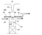
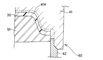
そして、ドアトリムアッパー20とドアトリムロア30との境界部分には、境界溝部17が設定されており、特に本発明を適用したドアトリム10は、ドアトリムアッパー20側の樹脂基材21が境界溝部17を越えてドアトリムロア30側に染み出すことがなく、同様に、ドアトリムロア30においても、境界溝部17からドアトリムアッパー20側に染み出すことが可及的に防止できる構成になっている。すなわち、図2,図3に示すように、境界溝部17近傍部分の構成については、ドアトリムアッパー20とドアトリムロア30は一般部と同一の板厚(図3中符号dで示す)を確保した上で、それに加えて、それぞれ同一方向に直線状に延びる複数の凹凸層20a,30aが一体化されている。双方の凹凸層20a,30aの厚み(図3中符号hで示す)は、0.01〜0.5mm程度に設定されている。
A
次いで、上述したドアトリム10の成形に使用する成形金型40の構成について、図4乃至図6を基に説明する。まず、図4に示すように、ドアトリム10の成形に使用する成形金型40は、所定ストローク上下動可能な成形上型41と、成形上型41と対をなす固定側の成形下型42と、成形下型42に接続される2基の射出機43a,43bとから大略構成されている。更に詳しくは、成形上型41は、製品形状に合致したキャビティ部411が成形されており、成形上型41の上面に連結された昇降シリンダ412により所定ストローク上下駆動される。また、成形上型41の4隅部には、ガイド機構となるガイドブッシュ413が設けられている。
Next, the configuration of the molding die 40 used for molding the door trim 10 will be described with reference to FIGS. First, as shown in FIG. 4, a
一方、成形下型42には、成形上型41のキャビティ部411に対応するコア部421が設けられている。また、このコア部421の型面に溶融樹脂を供給するために、成形下型42にマニホールド422a,422b、ゲート423a,423bが設けられており、このマニホールド422a,422b、ゲート423a,423bの樹脂通路を経て射出機43a,43bから供給される溶融樹脂M1,M2がコア部421の上面に形成されたドアトリムアッパー20の樹脂基材21を成形するためのキャビティ424内、及びドアトリムロア30を成形するためのキャビティ425内に供給される。また、成形下型42の4隅部には、ガイド機構となるガイドポスト426が突設され、このガイドポスト426は、成形上下型41,42が型締め及び型開きされる際、ガイドブッシュ413内に案内されることで成形上型41のプレス姿勢を適正に維持できる。
On the other hand, the molding lower die 42 is provided with a
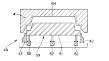
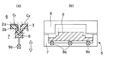
更に、図5に示すように、ドアトリム10に境界溝部17を形成するために、成形上型41には、凸条414が突設され、それに対応して成形下型42には、凹部427が形成され、この凹部427内に分割機構部50が収容配置されている。この分割機構部50は、分割バー51と駆動シリンダ52とから構成されており、分割バー51が駆動シリンダ52により所定ストローク昇降駆動される。また、上記分割バー51の上面には、成形上型41の凸条414を受容し、また、ドアトリムロア30の成形時には、補強リブ31を成形するための凹部51aが形成されている。
Further, as shown in FIG. 5, in order to form the
ところで、図2の拡大図並びに図3に示すように、境界溝部17の裏面側におけるドアトリムアッパー20及びドアトリムロア30には、一般部の板厚dを確保した状態で符号hで示す厚みをもつ凹凸層20a,30aが形成されているが、そのためには、図5に示すように、分割バー51の上面には、凹凸加工部53a,53b(一方側のキャビティ424に相当する凹凸加工部を符号53aで示し、他方側のキャビティ425に相当する凹凸加工部を符号53bで示す)が穿設加工されている。また、この実施例においては、溶融樹脂M1,M2の流速をより有効に低減させるために、分割バー51の上面に凹凸加工部53a,53bを形成することに加えて、成形下型42について、分割バー51と隣接する部分においてそれぞれ凹凸加工部44,45が穿設加工されている。この凹凸加工部44,45のエリアとしては、この実施例では、100mm程度に設定されている。尚、図6に示すように、成形下型42に設けられる分割機構部50は、ドアトリム10の境界溝部17に沿って設けられており、駆動シリンダ52の駆動により、分割バー51は、図8中実線で示す上方位置と、一点鎖線で示す下方位置との間で符号Lで示すストローク分昇降動作して、キャビティ424,425を区画、あるいは連通させる。
By the way, as shown in the enlarged view of FIG. 2 and FIG. 3, the door trim upper 20 and the door trim lower 30 on the back surface side of the
次いで、この成形金型40を使用してドアトリム10を成形する成形方法について、簡単に説明する。まず、ドアトリムアッパー20の成形工程は、表皮22を一方側のキャビティ424内にセットする。この時、成形金型40は、図4に示す型開き状態である。そして、表皮22は、図示しないセットピン、あるいは真空吸引作用により、成形上型41の型面に保持されている。尚、移動式のフレーム枠でキャビティ424内に表皮22をセットするようにしても良い。上記表皮22をセットした後、成形上型41の昇降シリンダ412が動作して、成形上型41が所定ストローク下降して、図7に示すように、成形上下型41,42が型締めされる。次いで、第1の射出機43aからマニホールド422a、ゲート423aを通じて溶融樹脂M1が一方側のキャビティ424内に射出充填される。尚、溶融樹脂M1の射出タイミングは、成形上下型41,42の型締め前に設定しても良い。また、この溶融樹脂M1としては、住友ノーブレンBUE81E6(住友化学工業製ポリプロピレン、メルトインデックス=65g/10分)が使用されており、所望ならば、タルクが適宜割り合いで混入されていても良い。
Next, a molding method for molding the door trim 10 using the molding die 40 will be briefly described. First, in the molding process of the door trim upper 20, the
このように、溶融樹脂M1が一方側のキャビティ424内に射出充填されて、表皮22を貼り合わせた樹脂基材21が成形され、ドアトリムアッパー20の成形が完了するが、この時、境界溝部17に沿って設けられている分割機構部50については、駆動シリンダ52が伸長状態であり、分割バー51は、図8に示すように、最上方位置に位置している。この時、図9に示すように、一方側のキャビティ424内に射出充填される溶融樹脂M1は、この分割バー51のシール作用により、他方側のキャビティ425内に侵入することがない。
In this way, the molten resin M1 is injected and filled into the
更に、一方側のキャビティ424内に射出充填される溶融樹脂M1は、特に、他方側のキャビティ425との境界部分に到達する際には、成形下型42の型面に形成されている凹凸加工部44及び分割バー51の上面に形成されている凹凸加工部53aにより、溶融樹脂M1の流速が低減化されて、他方側のキャビティ425側に染み出す恐れがない。従って、一方側のキャビティ424の端末部分のシール性が著しく向上しており、溶融樹脂M1の射出圧力を高く設定しても、外部への染み出しを確実に防止できるため、成形サイクルを短縮化できることから、生産性を高めることができる。
Further, when the molten resin M1 injected and filled into the
その後、ドアトリムアッパー20の成形が完了すれば、分割機構部50における駆動シリンダ52が収縮動作して、図10,図11に示すように、分割バー51が所定ストローク下降し、第2の射出機43bからマニホールド422b、ゲート423bを通じてドアトリムロア成形用の他方側のキャビティ425内に溶融樹脂M2が射出充填される。この時においても、図11に示すように、溶融樹脂M2が射出充填される際、成形下型42の型面に形成されている凹凸加工部45並びに分割バー51の上面に形成されている凹凸加工部53bにより、溶融樹脂M2の流速は分割バー51付近では低減化しており、キャビティ425の外部に染み出すことがなく、外観性能を良好に維持することができるとともに、射出圧を増大できることから、溶融樹脂M2の射出時間を短縮化することもできる。
Thereafter, when the molding of the door trim upper 20 is completed, the
このように、本発明に係るドアトリム10の成形方法によれば、分割バー51の上面に凹凸加工部53a,53bを形成する一方、この分割バー51の近傍部分における成形下型42の型面についても、凹凸加工部44,45を形成し、これら凹凸加工部53a,53b,44,45により、溶融樹脂M1,M2の流速を低減化させることにより、溶融樹脂M1,M2の外部への染み出しを確実に防止し、良好な外観性能を確保するとともに、射出時間を短縮化でき、生産性を高めることができるという利点を備えている。
As described above, according to the method for molding the door trim 10 according to the present invention, the concave and
更に、分割バー51の上面並びに近傍部分の成形下型42の金型型面をそれぞれフラット状に設定して成形した従来品と分割バー51の上面並びに近傍部分の成形下型42の型面にそれぞれ凹凸加工部53a,53b,44,45を穿設加工して成形した本発明品とを表1にて示す。両者を対比すれば、従来品と本発明品とでは溶融樹脂の充填時間については、本発明品のほうが板厚が厚いため遅くなり、かつ射出機の吐出圧についても本発明品が従来品に比べ低く設定でき、樹脂速度を本発明品のほうが低減できることが表1から明らかである。
Furthermore, the upper surface of the dividing

更に、溶融樹脂M1,M2の流速を低減化させる手段として、例えば、分割バー51の上面に凹凸加工部53a,53bを形成するだけで、成形下型42の型面に対する加工を省略しても良い。逆に、分割バー51の上面に対する加工を省略し、分割バー51の近傍部分における成形下型42の型面のみに凹凸加工部44,45を設定しても良い。
Furthermore, as a means for reducing the flow rate of the molten resins M1 and M2, for example, by simply forming the concave and
次いで、例えば、分割バー51の上面に形成される凹凸加工部53a,53bとして、上述した実施例では境界溝部17と平行に直線状に延びる凹凸加工部53a,53bを設定することにより、直線状に延びる凹凸層20a,30aを形成したが、凹凸層20a,30aは、断続的に設定することもでき、また、凹凸層20a,30aのライン方向についても溶融樹脂M1,M2をより有効に滞留させるように方向を相違させて樹脂流れを制御することもできる。
Next, for example, as the concavo-
また、凹凸層20a,30aを形成するために成形金型40の分割バー51の上面に形成する凹凸加工部53a,53bの形状は、上述した断面略半円形状の他に断面三角形状、断面四角形状のように、断面形状を任意に設定することができる。
Further, the shape of the concavo-
以上説明した実施例は、ドアトリムアッパー20とドアトリムロア30とからなる上下二分割構造のドアトリム10に適用したものであり、更に、ドアトリムアッパー20として、樹脂基材21と表皮22との積層構造体からなる構成を適用したが、単一の樹脂成形体からなるドアトリムアッパー20に適用することもできる。また、二色成形品の他に三色成形品にも応用できる。このように、多色成形品であれば、ドアトリム、リヤパーセルシェルフ、フロアトリム、トランクトリム、ラゲージトリム、ルーフトリム、リヤサイドトリム等、内装部品全般に適用することができる。
The embodiment described above is applied to the door trim 10 having the upper and lower split structure composed of the door trim upper 20 and the door trim lower 30. Further, as the door trim upper 20, a laminated structure of the
10 自動車用ドアトリム(ツートンタイプ)
17 境界溝部
20 ドアトリムアッパー(積層構造体)
20a 凹凸層
21 樹脂基材
22 表皮
30 ドアトリムロア(樹脂単体品)
30a 凹凸層
40 成形金型
41 成形上型
414 凸条
42 成形下型
424 キャビティ(ドアトリムアッパー成形用)
425 キャビティ(ドアトリムロア成形用)
43a,43b 射出機
44,45 凹凸加工部
50 分割機構部
51 分割バー
51a 凹部
52 駆動シリンダ
53a,53b 凹凸加工部
10 Automotive door trim (two-tone type)
17
20a Concavity and
30a Concavity and
425 Cavity (for door trim lower molding)
43a,
Claims (2)
前記分割バー(51)の上面及び分割バー(51)近傍の成形下型(42)型面の少なくとも一方側には凹凸加工部(53a,53b,44,45)が刻設されていることで、上記多色成形品(10)の境界溝部(17)近傍部分は、一般部分と同一厚みの基準厚み(d)に加えて厚み(h)の凹凸層(20a,30a)が一体化されていることを特徴とする多色成形品。 The cavity (C) of the molding die (40) is divided into a plurality of cavities (424, 425) by the dividing bar (51) and melted from the corresponding injection machines (43a, 43b) in each cavity (424, 425). Resin (M1, M2) is injected and filled into the cavities (424, 425), and a plurality of resin molded products (20, 30) are integrated based on the boundary groove (17) corresponding to the dividing bar (51). In the multi-color molded product (10) formed by
Asperity processed parts (53a, 53b, 44, 45) are engraved on at least one side of the upper surface of the dividing bar (51) and the molding lower mold (42) near the dividing bar (51). In the vicinity of the boundary groove (17) of the multicolor molded product (10), the uneven layer (20a, 30a) having the thickness (h) is integrated in addition to the reference thickness (d) having the same thickness as the general portion. A multicolor molded product characterized by
前記成形金型(40)内に内装される分割バー(51)の上面及びその周囲の成形下型(42)の型面の少なくとも一方側は、溶融樹脂(M1,M2)の流速を低減させる凹凸加工部(53a,53b,44,45)が一般面から穿設加工されていることで、一方側のキャビティ(424)内に溶融樹脂(M1)を充填する際、あるいは他方側のキャビティ(425)内に溶融樹脂(M2)を充填する際、分割バー(51)の近傍部分で溶融樹脂(M1,M2)の流速が低減され、射出機(43a,43b)の吐出圧を低減できることを特徴とする多色成形品の成形方法。 The cavity (C) of the molding die (40) is divided into a plurality of cavities (424, 425) by the dividing bar (51) and melted from the corresponding injection machines (43a, 43b) in each cavity (424, 425). Resin (M1, M2) is injected and filled into the cavities (424, 425), and a plurality of resin molded products (20, 30) are integrated based on the boundary groove (17) corresponding to the dividing bar (51). In the method for forming a multicolor molded article (10) obtained by
At least one side of the upper surface of the dividing bar (51) and the molding surface of the molding lower mold (42) around it in the molding die (40) reduces the flow rate of the molten resin (M1, M2). The concave and convex portions (53a, 53b, 44, 45) are perforated from the general surface, so that when the molten resin (M1) is filled into the cavity (424) on one side or the cavity ( 425) When the molten resin (M2) is filled in, the flow rate of the molten resin (M1, M2) is reduced in the vicinity of the dividing bar (51), and the discharge pressure of the injection machines (43a, 43b) can be reduced. A method for forming a multi-color molded product.
Priority Applications (1)
| Application Number | Priority Date | Filing Date | Title |
|---|---|---|---|
| JP2005344220A JP2007144871A (en) | 2005-11-29 | 2005-11-29 | Multicolor molded product and its molding method |
Applications Claiming Priority (1)
| Application Number | Priority Date | Filing Date | Title |
|---|---|---|---|
| JP2005344220A JP2007144871A (en) | 2005-11-29 | 2005-11-29 | Multicolor molded product and its molding method |
Publications (1)
| Publication Number | Publication Date |
|---|---|
| JP2007144871A true JP2007144871A (en) | 2007-06-14 |
Family
ID=38206846
Family Applications (1)
| Application Number | Title | Priority Date | Filing Date |
|---|---|---|---|
| JP2005344220A Pending JP2007144871A (en) | 2005-11-29 | 2005-11-29 | Multicolor molded product and its molding method |
Country Status (1)
| Country | Link |
|---|---|
| JP (1) | JP2007144871A (en) |
Cited By (3)
| Publication number | Priority date | Publication date | Assignee | Title |
|---|---|---|---|---|
| JP2009241463A (en) * | 2008-03-31 | 2009-10-22 | Daihatsu Motor Co Ltd | Injection molding die and injection molding method |
| JP2010184366A (en) * | 2009-02-10 | 2010-08-26 | Kasai Kogyo Co Ltd | Method of molding two-color molded article and molding mold of the same |
| CN101905510A (en) * | 2009-06-04 | 2010-12-08 | 株式会社东芝 | Dual-color shaping mold, dual-color shaped part and manufacturing method of dual-color shaped part |
Citations (3)
| Publication number | Priority date | Publication date | Assignee | Title |
|---|---|---|---|---|
| JP2001191361A (en) * | 2000-01-14 | 2001-07-17 | Konan Tokushu Sangyo Kk | Method and apparatus for molding resin molded product with skin |
| JP2004017629A (en) * | 2002-06-20 | 2004-01-22 | Idemitsu Petrochem Co Ltd | Molding method for resin molded body |
| JP2004017627A (en) * | 2002-06-20 | 2004-01-22 | Araco Corp | Mold for injection molding |
-
2005
- 2005-11-29 JP JP2005344220A patent/JP2007144871A/en active Pending
Patent Citations (3)
| Publication number | Priority date | Publication date | Assignee | Title |
|---|---|---|---|---|
| JP2001191361A (en) * | 2000-01-14 | 2001-07-17 | Konan Tokushu Sangyo Kk | Method and apparatus for molding resin molded product with skin |
| JP2004017629A (en) * | 2002-06-20 | 2004-01-22 | Idemitsu Petrochem Co Ltd | Molding method for resin molded body |
| JP2004017627A (en) * | 2002-06-20 | 2004-01-22 | Araco Corp | Mold for injection molding |
Cited By (4)
| Publication number | Priority date | Publication date | Assignee | Title |
|---|---|---|---|---|
| JP2009241463A (en) * | 2008-03-31 | 2009-10-22 | Daihatsu Motor Co Ltd | Injection molding die and injection molding method |
| JP2010184366A (en) * | 2009-02-10 | 2010-08-26 | Kasai Kogyo Co Ltd | Method of molding two-color molded article and molding mold of the same |
| CN101905510A (en) * | 2009-06-04 | 2010-12-08 | 株式会社东芝 | Dual-color shaping mold, dual-color shaped part and manufacturing method of dual-color shaped part |
| JP2010280134A (en) * | 2009-06-04 | 2010-12-16 | Toshiba Corp | Mold for two-color molding, two-color molded article, and method of manufacturing the same |
Similar Documents
| Publication | Publication Date | Title |
|---|---|---|
| JP4107583B2 (en) | Interior parts for automobiles and manufacturing method thereof | |
| JP2011011352A (en) | Method and mold for molding multi-color molded article | |
| JP2008030300A (en) | Two-color molding and its molding method | |
| JP2008155395A (en) | Method and apparatus for molding laminated molding | |
| JP3904204B2 (en) | Interior parts for automobile and terminal processing method thereof | |
| JP2009073112A (en) | Molding method of two-color molded product and mold | |
| JP4133451B2 (en) | Interior parts for automobile, manufacturing method thereof and molding die | |
| JP2008173793A (en) | Car trim part and its manufacturing method | |
| JP2004231030A (en) | Interior parts for automobile manufacturing method thereof, and molding die for the same | |
| JP2007144871A (en) | Multicolor molded product and its molding method | |
| JP2009154428A (en) | Automobile interior component, and method for producing the same | |
| JP4618722B2 (en) | Manufacturing method for interior parts for automobiles | |
| JP2007030291A (en) | Multi-color molding, method and mold for molding the molding | |
| JP4591921B2 (en) | Multicolor molded product and molding method thereof | |
| JP4251443B2 (en) | Manufacturing method for interior parts for automobiles | |
| JP2009255470A (en) | Interior trim for car | |
| JP4135916B2 (en) | Manufacturing method for interior parts for automobiles | |
| JP2005329544A (en) | Two-color molded product and its molding method | |
| JP2008173896A (en) | Automotive interior trim and its manufacturing process | |
| JP5403800B2 (en) | Multicolor molded product molding method and molding apparatus | |
| JP2008194984A (en) | Two-color molding and its molding method | |
| JP2008006620A (en) | Automotive interior trim and its manufacturing method | |
| JP4636604B2 (en) | Molding method for multicolor molded products | |
| JP2008080885A (en) | Automotive interior part | |
| JP2007130914A (en) | Multicolor molded article and its molding method |
Legal Events
| Date | Code | Title | Description |
|---|---|---|---|
| A621 | Written request for application examination |
Effective date: 20081007 Free format text: JAPANESE INTERMEDIATE CODE: A621 |
|
| A977 | Report on retrieval |
Effective date: 20110309 Free format text: JAPANESE INTERMEDIATE CODE: A971007 |
|
| A131 | Notification of reasons for refusal |
Effective date: 20110311 Free format text: JAPANESE INTERMEDIATE CODE: A131 |
|
| A02 | Decision of refusal |
Effective date: 20110704 Free format text: JAPANESE INTERMEDIATE CODE: A02 |