JP2007137724A - Glass-made mold - Google Patents
Glass-made mold Download PDFInfo
- Publication number
- JP2007137724A JP2007137724A JP2005334619A JP2005334619A JP2007137724A JP 2007137724 A JP2007137724 A JP 2007137724A JP 2005334619 A JP2005334619 A JP 2005334619A JP 2005334619 A JP2005334619 A JP 2005334619A JP 2007137724 A JP2007137724 A JP 2007137724A
- Authority
- JP
- Japan
- Prior art keywords
- film
- glass
- mold
- release film
- mold body
- Prior art date
- Legal status (The legal status is an assumption and is not a legal conclusion. Google has not performed a legal analysis and makes no representation as to the accuracy of the status listed.)
- Pending
Links
Images

Abstract
Description
本発明はガラス製成形型に関する。詳細には、例えば、例えばガラス製光学素子等のガラス被成形物をプレス成形するためのガラス製成形型に関する。 The present invention relates to a glass mold. Specifically, for example, the present invention relates to a glass mold for press-molding a glass object such as a glass optical element.
従来、レンズ等の光学素子の製造方法として、精密プレス成形法が提案されている。精密プレス成形法とは、所定の温度に加熱したガラス材を成形型を用いてプレス成形する方法である。 Conventionally, a precision press molding method has been proposed as a method of manufacturing an optical element such as a lens. The precision press molding method is a method of press molding a glass material heated to a predetermined temperature using a molding die.
一般的に、ガラス材の精密プレス成形は高温雰囲気中で行われるため、精密プレス成形にはセラミック製や超硬合金製の成形型が用いられている。しかしながら、セラミックス製や超硬合金製の成形型を作製するためには、母材を高剛性の超精密CNC旋盤などにより超精密に切削、研削し、且つ表面を研磨しなければならない。このため、セラミックス製や超硬合金製の成形型は、作製コストが高く、且つ作製に要する時間が長いという問題がある。さらに、成形型ごとに切削加工等を行うために、成形型に形状ばらつきが生じやすいという問題もある。 In general, since precision press molding of a glass material is performed in a high temperature atmosphere, a molding die made of ceramic or cemented carbide is used for precision press molding. However, in order to produce a mold made of ceramics or cemented carbide, the base material must be ultra-precisely cut and ground with a high-rigidity ultra-precise CNC lathe and the surface must be polished. For this reason, the molds made of ceramics or cemented carbide have a problem that the production cost is high and the time required for the production is long. Furthermore, since cutting or the like is performed for each mold, there is a problem that shape variations are likely to occur in the mold.
このような問題に鑑み、例えば特許文献1〜3には、ガラス製の成形型が提案されている。
しかしながら、ガラス製の成形型をそのまま用いてガラス被成形物をプレス成形すると、成形型とガラス被成形物とが融着してしまうという問題がある。このため、一般的に、ガラス製の成形型本体の成形面には、ガラスに対して離型性のよい離型膜が形成されている。且つ、ガラスに対して離型性のよい離型膜とガラス製の成形型本体との密着性を向上させるため、成形型本体と離型膜との間に密着膜が形成されている。 However, when a glass molding is press-molded using a glass molding die as it is, there is a problem that the molding die and the glass molding are fused. For this reason, in general, a mold release film having good mold releasability is formed on the molding surface of the glass mold main body. In addition, an adhesion film is formed between the mold body and the mold release film in order to improve the adhesion between the mold release film having good mold releasability and the glass mold body.
しかしながら、従来のガラス製成形型では、離型膜と成形型本体との密着性が十分ではなく、プレス成形中に離型膜が成形型本体から剥離してしまうという問題がある。すなわち、従来のガラス製成形型は製品寿命が短いという問題がある。 However, the conventional glass mold has insufficient adhesion between the mold release film and the mold body, and there is a problem that the mold release film peels off from the mold body during press molding. That is, the conventional glass mold has a problem that the product life is short.
本発明は係る点に鑑みてなされたものであり、その目的とするところは、長い製品寿命を有するガラス製成形型を提供することにある。 The present invention has been made in view of the above points, and an object of the present invention is to provide a glass mold having a long product life.
本発明に係るガラス製成形型は、柱状の成形型本体と、離型膜と、密着膜とを備えている。成形型本体は実質的にガラスにより形成されている。離型膜は成形型本体の一方の端面を覆うように形成されている。密着膜は成形型本体と離型膜との間に設けられている。 The glass mold according to the present invention includes a columnar mold body, a release film, and an adhesion film. The mold body is substantially made of glass. The release film is formed so as to cover one end surface of the mold body. The adhesion film is provided between the mold body and the release film.
離型膜及び密着膜は、離型膜の膜応力及び密着膜の膜応力が成形型本体に及ぼす力の合計の絶対値が4000N/m以下となるように形成されている。 The release film and the adhesion film are formed so that the absolute value of the total force exerted on the mold body by the film stress of the release film and the film stress of the adhesion film is 4000 N / m or less.
尚、本明細書において、「膜応力」とは膜が被成膜体に及ぼす膜面方向の力(圧縮応力、引っ張り応力)のことをいう。 In this specification, “film stress” refers to the force (compressive stress, tensile stress) in the film surface direction that the film exerts on the film formation target.
本発明によれば、離型膜と成形型本体との高い密着性を実現できるので、製品寿命の長いガラス製成形型を実現することができる。 According to the present invention, high adhesion between the release film and the mold main body can be realized, so that a glass mold having a long product life can be realized.
以下、本発明の実施形態について、図面を参照しながら詳細に説明する。 Hereinafter, embodiments of the present invention will be described in detail with reference to the drawings.
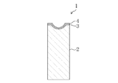
図1は本実施形態に係るガラス製成形型1の断面図である。
FIG. 1 is a cross-sectional view of a
本実施形態に係るガラス製成形型1は、ガラス製光学素子等のガラス被成形物をプレス成形するためのものである。
A
ガラス製成形型1は、成形型本体2と、密着膜3と、離型膜4とを備えている。離型膜は成形型本体2の一方の端面を覆うように形成されている。密着膜3は成形型本体2と離型膜4との間に設けられている。
The
成形型本体2は、実質的にガラスにより柱状(例えば、円柱状又は角柱状)に形成されている。詳細には、成形型本体2は、プレス成形するガラス被成形物(例えば、ガラス製光学素子)の軟化温度よりも高いガラス転移温度を有するガラス(結晶化ガラスを含む)により実質的に形成されていることが好ましい。そうすることによって、ガラス被成形物を成形する際の成形型本体2の形状寸法の変化を抑制することができる。具体的には、成形型本体2は、例えば、シリカガラス、ホウ珪酸ガラス、石英ガラス等により形成されていることが好ましい。さらに具体的には、例えば、ガラス転移温度が690℃、軟化温度が740℃、100℃〜300℃における線熱膨張係数が64×10-7/℃のホウ珪酸ガラスにより形成してもよい。 The mold body 2 is substantially formed in a columnar shape (for example, a columnar shape or a prismatic shape) from glass. Specifically, the mold body 2 is substantially formed of glass (including crystallized glass) having a glass transition temperature higher than the softening temperature of a glass molded object (for example, a glass optical element) to be press-molded. It is preferable. By doing so, the change of the shape dimension of the shaping | molding die main body 2 at the time of shape | molding a glass to-be-molded object can be suppressed. Specifically, the mold body 2 is preferably formed of, for example, silica glass, borosilicate glass, quartz glass, or the like. More specifically, for example, the glass transition temperature may be 690 ° C., the softening temperature may be 740 ° C., and the linear thermal expansion coefficient at 100 ° C. to 300 ° C. may be 64 × 10 −7 / ° C.
尚、成形型本体2は、例えば、ガラス材をプレス成形することにより形成することができる。また、柱状のガラス材に切削・研磨等の物理的加工を施すことにより形成してもよい。 The mold body 2 can be formed by, for example, press molding a glass material. Moreover, you may form by giving physical processing, such as cutting and grinding | polishing, to columnar glass material.
成形型本体2の一方の端面はガラス被成形物をプレスするためのプレス面を構成している。プレス面は、例えば、凹状又は凸状に形成されていてもよい。離型膜4はこのプレス面を覆うように形成されている。 One end surface of the mold body 2 constitutes a pressing surface for pressing the glass molding. The press surface may be formed in a concave shape or a convex shape, for example. The release film 4 is formed so as to cover the press surface.
離型膜4は、ガラス製成形型1に対するガラス被成形物(例えば、ガラス製光学素子)の離型性を向上するものである。この離型膜4を設けることにより、ガラス被成形物のガラス製成形型1への融着を抑制することができる。離型膜4は、例えば、Pt、Pd、Rh、Ir、Os、Ru、Re、W、及びTaからなる群より選ばれた金属、若しくは、Pt、Pd、Rh、Ir、Os、Ru、Re、W、及びTaからなる群より選ばれた1種以上の金属を含む合金により形成することができる。
The release film 4 improves the releasability of a glass molded object (for example, a glass optical element) with respect to the
離型膜4はガラスに対する密着性が低いものである。このため、離型膜4をガラス製の成形型本体2の上に強固に成膜することは困難である。仮に、離型膜4を成形型本体2の上に直接成膜した場合、離型膜4は非常に成形型本体2から剥離しやすいものとなる。 The release film 4 has low adhesion to glass. For this reason, it is difficult to firmly form the release film 4 on the glass mold body 2. If the release film 4 is formed directly on the mold body 2, the release film 4 is very easy to peel from the mold body 2.
密着膜3は、この離型膜4の成形型本体2からの剥離を抑制するための膜であり、離型膜4とガラス製の成形型本体2との両方に対して高い密着性を示すものであることが好ましい。密着膜3は、例えば、Ti、Cr、Ni、Ta、Mo、Zr、Co、及びCuからなる群より選ばれた金属、若しくは、Ti、Cr、Ni、Ta、Mo、Zr、Co、及びCuからなる群より選ばれた1種以上の金属を含む合金により形成することができる。
The
尚、密着膜3、離型膜4の形成方法としては、例えば、スパッタ法、蒸着法、CVD法等が挙げられる。
In addition, as a formation method of the adhesion | attachment film |
本実施形態では、密着膜3及び離型膜4は、離型膜4の膜応力及び密着膜3の膜応力が成形型本体2に及ぼす力の合計の絶対値が4000N/m以下となるように形成されている。言い換えれば、離型膜4の膜応力及び密着膜3の膜応力が成形型本体2に及ぼす力の合計が−4000N/m以上+4000N/m以下となるように形成されている。このため、離型膜4の成形型本体2からの剥離が効果的に抑制されている。離型膜4の膜応力及び密着膜3の膜応力が成形型本体2に及ぼす力の合計の絶対値が4000N/mよりも大きい場合は、その膜応力によって、又は、その膜応力とガラス被成形物の成形時に密着膜3、離型膜4と成形型本体2との間に発生する応力とによって離型膜4が(又は、離型膜4と密着膜3とが)剥離しやすくなる。
In the present embodiment, the
尚、密着膜3、離型膜4の膜応力は、それらの成膜条件を変化させることにより調整制御することができる。例えば、密着膜3、離型膜4をスパッタ法により形成する場合、ハウジング内の各ガスの分圧を調節することにより各膜の膜応力を調節することができる。
The film stress of the
また、膜応力は、例えば、膜応力を測定しようとする薄膜を形成したガラス基板を用いて測定したデータから算出することができる。具体的には、膜応力は、形成された薄膜の膜応力によってガラス基板が反った量を測定し、その得られた反り量から算出することができる(以下、本測定法をたわみ測定法と記す)。離型膜4の膜応力及び密着膜3の膜応力が成形型本体2に及ぼす力は、測定された膜応力と膜厚により算出することができる。
Further, the film stress can be calculated from data measured using a glass substrate on which a thin film on which the film stress is to be measured is formed, for example. Specifically, the film stress can be calculated from the amount of warpage obtained by measuring the amount of warpage of the glass substrate due to the film stress of the formed thin film (hereinafter, this measurement method is referred to as deflection measurement method). Write down). The force exerted on the mold body 2 by the film stress of the release film 4 and the film stress of the
図1に示す上記実施形態に係るガラス製成形型1と同様の構成を有するガラス製成形型を、離型膜4及び密着膜3を種々変化させて作製し、実施例1〜4、及び比較例1、2とした。尚、本実施例及び比較例の説明において、図1を上記実施形態と共通に参照する。
A glass mold having the same configuration as that of the
実施例1〜4、及び比較例1、2において、成形型本体2は、ホウ珪酸ガラス(ガラス転移温度:690℃、軟化温度(屈伏点):740℃、100℃〜300℃における線熱膨張係数:64×10-7/℃)をプレス成形することにより形成した。成形型本体2の成形面は、半径6mm、曲率半径5mmの凹状に形成した。 In Examples 1 to 4 and Comparative Examples 1 and 2, the mold body 2 was made of borosilicate glass (glass transition temperature: 690 ° C., softening temperature (deflection point): 740 ° C., linear thermal expansion at 100 ° C. to 300 ° C. (Coefficient: 64 × 10 −7 / ° C.). The molding surface of the mold body 2 was formed in a concave shape having a radius of 6 mm and a curvature radius of 5 mm.
成形型本体2の上に、アルゴン0.1Pa、300Wの条件下でスパッタ法により密着膜3を形成した。尚、密着膜3は、実施例1及び比較例2ではCrにより形成した。実施例2ではTiにより、実施例3及び比較例1ではTaにより、実施例4ではCoにより形成した。また、密着膜3の膜厚は、実施例1、2、4、及び比較例2では0.2μm、実施例3及び比較例1では0.1μmとした。
An
次に、密着膜3の上に、アルゴン0.2Pa、300Wの条件下でスパッタ法により離型膜4を形成し、ガラス製成形型1を完成させた。尚、離型膜4は、実施例1、2、比較例1ではPt−Irにより形成した。実施例3及び比較例2ではIr−Taにより、実施例4ではPt−Wにより形成した。また、離型膜4の膜厚は、実施例1〜4、及び比較例1、2において、それぞれ0.4μm、1.3μm、0.7μm、0.7μm、1.1μm、1.3μmとした。
Next, the release film 4 was formed on the
次に、別途、ガラス基板(厚さ15mm)上に、実施例1〜4、及び比較例1、2と同様の構成の密着膜3及び離型膜4を同様の条件で形成した。形成した密着膜3及び離型膜4の膜応力を、たわみ測定法で測定した。実施例1では、密着膜3の膜応力は3×10⁷Pa、離型膜4の膜応力は3×10⁹Paであった。
Next, an
得られた膜応力に膜厚をかけることによって離型膜4の膜応力及び密着膜3の膜応力が成形型本体2に及ぼす力の合計を算出した。算出された力は、実施例1〜4、及び比較例1、2において、それぞれ1406N/m、3906N/m、2617N/m、2100N/m、4017N/m、4556N/mであった。実施例1〜4では、算出された力の絶対値は4000N/m以下であった。一方、比較例1、2では、算出された力の絶対値は4000N/mより大きかった。
By adding the film thickness to the obtained film stress, the total force exerted on the mold body 2 by the film stress of the release film 4 and the film stress of the
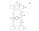
次に、図2に示すように、作製されたガラス製成形型1を上型13及び下型15として用いてガラスレンズ18を1000回成形した。
Next, as shown in FIG. 2, the
図2はガラスレンズ18の成形に用いた製造装置10の構成を表す断面図である。
FIG. 2 is a cross-sectional view showing the configuration of the
図3はガラスレンズ18の製造工程を表す図である。
FIG. 3 is a diagram illustrating a manufacturing process of the
製造装置10は、ヒーター12が埋設された上プレス盤11及び下プレス盤16とを備えている。上プレス盤11と下プレス盤16との間には成形型組が配置されている。成形型組は、上記工程で作製された上型13及び下型15と、上型13及び下型15とが摺動可能に挿入された円柱状の胴型14とを備えている。
The
この製造装置10にガラスレンズ18の材料となるガラス材17を装入し、窒素雰囲気中において、1000回プレス成形を行った。具体的には、上型13から0.5mm離間させて配置した上プレス盤11と下プレス盤16とをそれぞれ600℃まで加熱し、30秒間保持した。その後、上プレス盤11を50kgfで押圧することによりプレス成形を行い、その後冷却することによりガラスレンズ18を作製した。尚、ガラス材17は住田光学ガラス社製K−PBK40(ガラス転移温度:501℃、屈伏点:549℃)を用いた。
The
ガラスレンズ18を100回成形する毎に離型膜4の剥離の有無を目視により確認した。その結果を下記表1に示す。
Every time the

表1に示すように、実施例1〜4では、1000回成形後においても離型膜4の剥離は観察されなかった。一方、比較例1では、100回成形後の目視確認において離型膜4の剥離が観察された。また、比較例2では、ガラスレンズ18の成形前に離型膜4は自然に剥離した。
As shown in Table 1, in Examples 1 to 4, peeling of the release film 4 was not observed even after 1000 times molding. On the other hand, in Comparative Example 1, peeling of the release film 4 was observed in the visual confirmation after 100 times molding. In Comparative Example 2, the release film 4 naturally peeled before the
以上の結果から、離型膜4の膜応力及び密着膜3の膜応力が成形型本体2に及ぼす力の合計の絶対値が4000N/m以下である場合は、離型膜4の密着性が高いことがわかった。一方、4000N/mより大きい場合は、離型膜4の密着性が低いことがわかった。すなわち、離型膜4の膜応力及び密着膜3の膜応力が成形型本体2に及ぼす力の合計の絶対値を4000N/m以下とすることで、製品寿命の長いガラス製成形型を実現可能なことがわかった。
From the above results, when the absolute value of the total force exerted on the mold body 2 by the film stress of the release film 4 and the film stress of the
尚、実施例1〜4及び比較例1、2では、圧縮応力が働いたが、離型膜4、密着膜3と成形型本体2との密着性を考える上では、圧縮応力が働く場合も引っ張り応力が働く場合も同様の結果が得られるものと予想される。
In Examples 1 to 4 and Comparative Examples 1 and 2, the compressive stress worked. However, when considering the adhesiveness between the release film 4 and the
以上説明したように、本発明に係るガラス製成形型は、離型膜と成形型本体との密着性が高く、長い製品寿命を有するため、レンズ、プリズム等の光学素子、ガラス素子を成形するためのガラス製成形型等の製造に有用である。 As described above, the glass mold according to the present invention has high adhesion between the release film and the mold body, and has a long product life, and therefore, molds optical elements such as lenses and prisms, and glass elements. Therefore, it is useful for producing a glass mold for the purpose.
1 ガラス製成形型
2 成形型本体
3 密着膜
4 離型膜
10 製造装置
11 上プレス盤
12 ヒーター
13 上型
14 胴型
15 下型
16 下プレス盤
17 ガラス材
18 ガラスレンズ
1 Glass mold
2 Mold body
3 Adhesive film
4 Release film
10 Manufacturing equipment
11 Upper press
12 Heater
13 Upper mold
14 Body type
15 Lower mold
16 Lower press panel
17 Glass material
18 Glass lens
Claims (4)
上記成形型本体の一方の端面を覆うように形成された離型膜と、
上記成形型本体と上記離型膜との間に設けられた密着膜と、
を備え、
上記離型膜及び上記密着膜は、該離型膜の膜応力及び該密着膜の膜応力が上記成形型本体に及ぼす力の合計の絶対値が4000N/m以下となるように形成されているガラス製成形型。 A columnar mold body formed substantially of glass;
A release film formed so as to cover one end face of the mold body;
An adhesion film provided between the mold body and the release film;
With
The release film and the adhesion film are formed so that the absolute value of the total stress exerted on the mold body by the film stress of the release film and the film stress of the adhesion film is 4000 N / m or less. Glass mold.
上記密着膜は、Ti、Cr、Ni、Ta、Mo、Zr、Co、及びCuからなる群より選ばれた金属、若しくは、Ti、Cr、Ni、Ta、Mo、Zr、Co、及びCuからなる群より選ばれた1種以上の金属を含む合金により形成されているガラス製成形型。 The glass mold according to claim 1,
The adhesion film is made of a metal selected from the group consisting of Ti, Cr, Ni, Ta, Mo, Zr, Co, and Cu, or made of Ti, Cr, Ni, Ta, Mo, Zr, Co, and Cu. A glass mold formed of an alloy containing at least one metal selected from the group.
上記離型膜は、Pt、Pd、Rh、Ir、Os、Ru、Re、W、及びTaからなる群より選ばれた金属、若しくは、Pt、Pd、Rh、Ir、Os、Ru、Re、W、及びTaからなる群より選ばれた1種以上の金属を含む合金により形成されているガラス製成形型。 The glass mold according to claim 1,
The release film may be a metal selected from the group consisting of Pt, Pd, Rh, Ir, Os, Ru, Re, W, and Ta, or Pt, Pd, Rh, Ir, Os, Ru, Re, W, And a glass mold formed of an alloy containing at least one metal selected from the group consisting of Ta.
上記成形型本体は、ガラス製光学素子をプレス成形するためのものであり、該ガラス製光学素子の軟化温度よりも高いガラス転移温度を有するガラス製成形型。 The glass mold according to claim 1,
The mold body is a glass mold for press-molding a glass optical element and has a glass transition temperature higher than a softening temperature of the glass optical element.
Priority Applications (1)
| Application Number | Priority Date | Filing Date | Title |
|---|---|---|---|
| JP2005334619A JP2007137724A (en) | 2005-11-18 | 2005-11-18 | Glass-made mold |
Applications Claiming Priority (1)
| Application Number | Priority Date | Filing Date | Title |
|---|---|---|---|
| JP2005334619A JP2007137724A (en) | 2005-11-18 | 2005-11-18 | Glass-made mold |
Publications (1)
| Publication Number | Publication Date |
|---|---|
| JP2007137724A true JP2007137724A (en) | 2007-06-07 |
Family
ID=38201048
Family Applications (1)
| Application Number | Title | Priority Date | Filing Date |
|---|---|---|---|
| JP2005334619A Pending JP2007137724A (en) | 2005-11-18 | 2005-11-18 | Glass-made mold |
Country Status (1)
| Country | Link |
|---|---|
| JP (1) | JP2007137724A (en) |
Cited By (1)
| Publication number | Priority date | Publication date | Assignee | Title |
|---|---|---|---|---|
| JP2009046320A (en) * | 2007-08-13 | 2009-03-05 | Sumita Optical Glass Inc | Mold for shaping optical glass element |
-
2005
- 2005-11-18 JP JP2005334619A patent/JP2007137724A/en active Pending
Cited By (2)
| Publication number | Priority date | Publication date | Assignee | Title |
|---|---|---|---|---|
| JP2009046320A (en) * | 2007-08-13 | 2009-03-05 | Sumita Optical Glass Inc | Mold for shaping optical glass element |
| JP4585558B2 (en) * | 2007-08-13 | 2010-11-24 | 株式会社住田光学ガラス | Optical glass element mold |
Similar Documents
| Publication | Publication Date | Title |
|---|---|---|
| JPH0616433A (en) | Die for press-forming optical element | |
| JP2007148401A (en) | Axial symmetric glass lens | |
| JP2006290700A (en) | Mold for glass optical element and method of manufacturing glass optical element | |
| JP2004359481A (en) | Method for manufacturing replica pattern for lens molding | |
| JP2006225190A (en) | Metallic mold for molding optical element and its manufacturing method | |
| JP2007137724A (en) | Glass-made mold | |
| JP2001302273A (en) | Mold for molding optical glass element | |
| JP2001302260A (en) | Method for molding optical element | |
| JPH0421608B2 (en) | ||
| JP2002274867A (en) | Optical glass element press forming die and optical glass element | |
| JPH11268920A (en) | Forming mold for forming optical element and its production | |
| JP2003277078A (en) | Die for glass molding and method for manufacturing the sane, method for manufacturing glass optical element, glass optical element and diffraction optical element | |
| JP2004210550A (en) | Molding mold | |
| JP4373257B2 (en) | Optical element molding die, method for manufacturing the same, and optical element | |
| JP2009073693A (en) | Optical element-molding die, and method for producing the same | |
| JP3185299B2 (en) | Glass lens molding die and glass lens molding device | |
| JP2006124214A (en) | Method of molding optical device and die for molding optical device | |
| JP2003048723A (en) | Press forming method and press formed equipment | |
| JPH06144850A (en) | Mold for forming optical glass element and method of forming optical glass element | |
| JP3109219B2 (en) | Glass optical element molding die and method of manufacturing the same | |
| JPS61242922A (en) | Pressing mold for optical glass element | |
| JP2004026607A (en) | Glass mold and method for manufacturing the same | |
| JP2006044968A (en) | Mold for molding optical element | |
| JPH11246229A (en) | Mold for molding optical element | |
| JPH0572336B2 (en) |