JP2007132526A - Bearing device for wheel - Google Patents
Bearing device for wheel Download PDFInfo
- Publication number
- JP2007132526A JP2007132526A JP2007031599A JP2007031599A JP2007132526A JP 2007132526 A JP2007132526 A JP 2007132526A JP 2007031599 A JP2007031599 A JP 2007031599A JP 2007031599 A JP2007031599 A JP 2007031599A JP 2007132526 A JP2007132526 A JP 2007132526A
- Authority
- JP
- Japan
- Prior art keywords
- diameter
- row
- inboard side
- ball
- pcdi
- Prior art date
- Legal status (The legal status is an assumption and is not a legal conclusion. Google has not performed a legal analysis and makes no representation as to the accuracy of the status listed.)
- Pending
Links
Images


Classifications
-
- F—MECHANICAL ENGINEERING; LIGHTING; HEATING; WEAPONS; BLASTING
- F16—ENGINEERING ELEMENTS AND UNITS; GENERAL MEASURES FOR PRODUCING AND MAINTAINING EFFECTIVE FUNCTIONING OF MACHINES OR INSTALLATIONS; THERMAL INSULATION IN GENERAL
- F16C—SHAFTS; FLEXIBLE SHAFTS; ELEMENTS OR CRANKSHAFT MECHANISMS; ROTARY BODIES OTHER THAN GEARING ELEMENTS; BEARINGS
- F16C19/00—Bearings with rolling contact, for exclusively rotary movement
- F16C19/02—Bearings with rolling contact, for exclusively rotary movement with bearing balls essentially of the same size in one or more circular rows
- F16C19/14—Bearings with rolling contact, for exclusively rotary movement with bearing balls essentially of the same size in one or more circular rows for both radial and axial load
- F16C19/18—Bearings with rolling contact, for exclusively rotary movement with bearing balls essentially of the same size in one or more circular rows for both radial and axial load with two or more rows of balls
- F16C19/181—Bearings with rolling contact, for exclusively rotary movement with bearing balls essentially of the same size in one or more circular rows for both radial and axial load with two or more rows of balls with angular contact
- F16C19/183—Bearings with rolling contact, for exclusively rotary movement with bearing balls essentially of the same size in one or more circular rows for both radial and axial load with two or more rows of balls with angular contact with two rows at opposite angles
- F16C19/184—Bearings with rolling contact, for exclusively rotary movement with bearing balls essentially of the same size in one or more circular rows for both radial and axial load with two or more rows of balls with angular contact with two rows at opposite angles in O-arrangement
- F16C19/186—Bearings with rolling contact, for exclusively rotary movement with bearing balls essentially of the same size in one or more circular rows for both radial and axial load with two or more rows of balls with angular contact with two rows at opposite angles in O-arrangement with three raceways provided integrally on parts other than race rings, e.g. third generation hubs
-
- F—MECHANICAL ENGINEERING; LIGHTING; HEATING; WEAPONS; BLASTING
- F16—ENGINEERING ELEMENTS AND UNITS; GENERAL MEASURES FOR PRODUCING AND MAINTAINING EFFECTIVE FUNCTIONING OF MACHINES OR INSTALLATIONS; THERMAL INSULATION IN GENERAL
- F16C—SHAFTS; FLEXIBLE SHAFTS; ELEMENTS OR CRANKSHAFT MECHANISMS; ROTARY BODIES OTHER THAN GEARING ELEMENTS; BEARINGS
- F16C2240/00—Specified values or numerical ranges of parameters; Relations between them
- F16C2240/40—Linear dimensions, e.g. length, radius, thickness, gap
- F16C2240/70—Diameters; Radii
- F16C2240/80—Pitch circle diameters [PCD]
-
- F—MECHANICAL ENGINEERING; LIGHTING; HEATING; WEAPONS; BLASTING
- F16—ENGINEERING ELEMENTS AND UNITS; GENERAL MEASURES FOR PRODUCING AND MAINTAINING EFFECTIVE FUNCTIONING OF MACHINES OR INSTALLATIONS; THERMAL INSULATION IN GENERAL
- F16C—SHAFTS; FLEXIBLE SHAFTS; ELEMENTS OR CRANKSHAFT MECHANISMS; ROTARY BODIES OTHER THAN GEARING ELEMENTS; BEARINGS
- F16C2326/00—Articles relating to transporting
- F16C2326/01—Parts of vehicles in general
- F16C2326/02—Wheel hubs or castors
Landscapes
- Engineering & Computer Science (AREA)
- General Engineering & Computer Science (AREA)
- Mechanical Engineering (AREA)
- Rolling Contact Bearings (AREA)
Abstract
Description
この発明は自動車等における車輪用軸受装置に関する。 The present invention relates to a wheel bearing device in an automobile or the like.
自動車の車輪は、懸架装置に車輪用軸受装置を介して回転自在に支持される。車輪用軸受装置に要求される機能としては、負荷容量や剛性の高いことが挙げられる。また自動車部品は、燃費向上等のために、軽量化が強く求められており、車輪用軸受装置においても軽量化が求められる。
従来の一般的な車輪用軸受装置は、負荷容量については満足できるが、車両旋回時の剛性が必ずしも十分とは言えない場合がある。また、自動車の安定した走行のために、車両旋回時の軸受剛性の向上が必要とされる。
車輪用軸受装置は、複列軸受が用いられており、直進時の車重は、複列軸受の中央に作用するように設計されている。しかし、車両の旋回時には、タイヤにかかる横力により、ハブフランジを傾けるようにモーメント荷重が発生する。そのため、複列のうちのアウトボード側列付近の剛性を高めることが求められる。
An automobile wheel is rotatably supported by a suspension device via a wheel bearing device. Functions required for the wheel bearing device include high load capacity and high rigidity. In addition, automobile parts are strongly required to be reduced in weight in order to improve fuel efficiency, and the weight reduction is also required in wheel bearing devices.
The conventional general wheel bearing device can satisfy the load capacity, but the rigidity at the time of turning of the vehicle may not always be sufficient. Further, for the stable running of the automobile, it is necessary to improve the bearing rigidity when the vehicle turns.
A double row bearing is used for the wheel bearing device, and the vehicle weight when traveling straight is designed to act on the center of the double row bearing. However, when the vehicle turns, a moment load is generated so that the hub flange is tilted by a lateral force applied to the tire. Therefore, it is required to increase the rigidity in the vicinity of the outboard side row in the double row.
アウトボード側列の剛性を高めるものとしては、例えば図7に示すように、複列のボール列Lo,Liのうち、アウトボード側列Loのボール7のPCD(ピッチ円直径)を、インボード側列Liの転動体8のPCDよりも大きくしたものが提案されている(例えば、特許文献1)。同特許文献1には、他の実施形態として、PCDを変える代わりに、アウトボード側列Loのボール7の個数をインボード側列Liのボール8の個数よりも多くすることなども提案されている。
特許文献1に示されようように、アウトボード側列LoのPCDをインボード側列LiのPCDよりも大きくすることや、アウトボード側列Loのボール個数を増やすことは、アウトボード側の剛性の向上には優れた手法である。また、両列ともPCDの増大やボール個数の増加を図るものと異なり、軸受装置全体の寸法,重量が増加することが回避される。
しかし、インボード側においても、安定した走行のためには軸受剛性を高めることが望まれる。インボード側では、周辺との関係で軸受寸法が制限されることが多く、軸受剛性を高めることが難しい。特に、内輪回転の車輪用軸受装置では、軌道面を内周に形成した外方部材をナックルの内径面に嵌合させて取付けることになるため、限られたナックル内径に対して、剛性を上げることが必要となる。
As shown in Patent Document 1, increasing the PCD of the outboard side row Lo than the PCD of the inboard side row Li, or increasing the number of balls in the outboard side row Lo, increases the rigidity on the outboard side. It is an excellent technique for improving In addition, unlike the ones that increase the PCD and the number of balls in both rows, an increase in the size and weight of the entire bearing device is avoided.
However, on the inboard side, it is desired to increase the bearing rigidity for stable running. On the inboard side, the bearing size is often limited in relation to the periphery, and it is difficult to increase the bearing rigidity. In particular, in an inner ring rotating wheel bearing device, since an outer member having a raceway surface formed on the inner periphery is fitted and attached to the inner diameter surface of the knuckle, the rigidity is increased with respect to the limited inner diameter of the knuckle. It will be necessary.
この発明の目的は、アウトボード側部分の剛性を高めると共に、インボード側部分においても、限られた軸受径で剛性の向上を図り、かつ転動疲労寿命が確保できる車輪用軸受装置を提供することである。 An object of the present invention is to provide a wheel bearing device capable of increasing rigidity of an outboard side portion, improving rigidity of the inboard side portion with a limited bearing diameter, and ensuring a rolling fatigue life. That is.
この発明における第1の発明の車輪用軸受装置は、インボード側端の外周に車体の懸架装置におけるナックルを嵌合させるナックル嵌合部を有し内周に複列の軌道面が設けられてインボード側の軌道面の全体または一部が前記ナックル嵌合部の設けられた軸方向範囲に重なる外方部材と、前記各軌道面に対向する複列の軌道面を外周に有しアウトボード側端の外周に車輪取付用のハブフランジを有する内方部材と、対向する軌道面間に介在した
ボールとを備えた車輪用軸受装置において、
アウトボード側のボール列のピッチ円直径を、インボード側のボール列のピッチ円直径よりも大きくし、アウトボード側列のボール個数をインボード側列のボール個数よりも多くし、
前記外方部材の前記ナックル嵌合部の外径Dに対するインボード側のボール列のピッチ円直径PCDiの割合(PCDi/D)を、
0.66≦(PCDi/D)≦0.80
としたことを特徴とする。
The wheel bearing device according to a first aspect of the present invention has a knuckle fitting portion for fitting a knuckle in a suspension device of a vehicle body on the outer periphery of the inboard side end, and a double row raceway surface is provided on the inner periphery. An outboard having an outer member in which the whole or a part of the raceway surface on the inboard side overlaps the axial range in which the knuckle fitting portion is provided, and a double row raceway surface facing each raceway surface on the outer periphery In a wheel bearing device comprising an inner member having a hub flange for wheel attachment on the outer periphery of the side end, and a ball interposed between opposing raceway surfaces,
The pitch circle diameter of the ball row on the outboard side is larger than the pitch circle diameter of the ball row on the inboard side, the number of balls on the outboard side row is larger than the number of balls on the inboard side row,
The ratio (PCDi / D) of the pitch circle diameter PCDi of the ball row on the inboard side to the outer diameter D of the knuckle fitting portion of the outer member,
0.66 ≦ (PCDi / D) ≦ 0.80
It is characterized by that.
この構成によると、アウトボード側のボール列のピッチ円直径を、インボード側のボール列のピッチ円直径よりも大きくしたため、軸受装置のアウトボード側部分の剛性を向上させることができる。また、アウトボード側列のボール個数をインボード側列のボール個数よりも多くしたことで、アウトボード側部分の剛性を一層向上させることができる。
この発明は、このようにアウトボード側の剛性を向上させた上で、外方部材の前記ナックル嵌合部の外径Dに対するインボード側のボール列のピッチ円直径PCDiの割合(PCDi/D)を、
0.66≦(PCDi/D)≦0.80
としたため、インボード側における剛性の向上、転動疲労寿命の確保が得られる。
According to this configuration, since the pitch circle diameter of the ball row on the outboard side is made larger than the pitch circle diameter of the ball row on the inboard side, the rigidity of the outboard side portion of the bearing device can be improved. Further, the rigidity of the outboard side portion can be further improved by increasing the number of balls in the outboard side row than the number of balls in the inboard side row.
In the present invention, after the rigidity on the outboard side is improved in this way, the ratio of the pitch circle diameter PCDi of the ball row on the inboard side to the outer diameter D of the knuckle fitting portion of the outer member (PCDi / D )
0.66 ≦ (PCDi / D) ≦ 0.80
Therefore, improvement in rigidity on the inboard side and securing of a rolling fatigue life can be obtained.
すなわち、外方部材のナックル嵌合部の外径Dは、軸受設計上で要求寸法として定まった値となる。そのため、このナックル嵌合部外径Dに対して、剛性の向上、転動疲労寿命の確保を図ることが必要となる。
上記ピッチ円直径PCDiは、インボード側の軌道面の内径D4からボール径dを差し引いた値であり、ボール径dが小さいほど、ボール中心が軌道面の内面に近づき、PCDiの値が軌道面内径D4の値に近づくことになる。ここで、インボード側軌道面は、ナックル嵌合部の内周に位置するため、ナックル嵌合部の外径Dが一定であって、外方部材における軌道面外周の必要最低肉厚tを確保できる範囲で可能な限り大きな値すると、軌道面内径D4は、D4=D−2×tであり、一定の値となる。
軌道面内径D4が一定であると、PCDi(=D4−d)の値は、ボール径dに依存することになる。ナックル嵌合部外径Dが一定と考えると、PCDi/Dの値は、ボール径dに依存することになり、ボール径が小さいほど、PCDi/Dの値が大きくなる。
ボール径dを小さくした場合、ボール個数を増やすことができて、それだけ支持点が増加するため、軸受剛性が高くなる。そのため剛性向上の点からは、ボール径が小さいほど好ましい。
ナックル嵌合部外径Dが一定であり、軌道面外周の必要肉厚tが一定であるとして、つまり軌道面内径D4が一定であるとして、PCDi/Dの変化による剛性,転動疲労寿命の関係を解析により求めた。その結果、PCDi/Dが0.66未満であると、車輪用軸受装置として剛性の向上にならず、またPCDi/Dが0.80よりも大きいと、車輪用軸受装置として転動疲労寿命が不足することが分かった。
0.66≦(PCDi/D)≦0.80
の範囲とすることで、剛性の向上の図りながら転動疲労寿命を確保することができる。
That is, the outer diameter D of the knuckle fitting portion of the outer member is a value determined as a required dimension in the bearing design. Therefore, it is necessary to improve the rigidity and secure the rolling fatigue life with respect to the outer diameter D of the knuckle fitting portion.
The pitch circle diameter PCDi is a value obtained by subtracting the ball diameter d from the inner diameter D4 of the track surface on the inboard side. The smaller the ball diameter d, the closer the ball center is to the inner surface of the track surface, and the value of PCDi is the track surface. It approaches the value of the inner diameter D4. Here, since the inboard side raceway surface is located on the inner circumference of the knuckle fitting portion, the outer diameter D of the knuckle fitting portion is constant, and the required minimum thickness t of the outer circumference of the raceway surface in the outer member is set. When the value is as large as possible within the range that can be secured, the raceway surface inner diameter D4 is D4 = D−2 × t, which is a constant value.
When the raceway inner diameter D4 is constant, the value of PCDi (= D4-d) depends on the ball diameter d. Assuming that the knuckle fitting outer diameter D is constant, the PCDi / D value depends on the ball diameter d, and the smaller the ball diameter, the larger the PCDi / D value.
When the ball diameter d is reduced, the number of balls can be increased and the support points are increased accordingly, so that the bearing rigidity is increased. Therefore, the smaller the ball diameter, the better from the viewpoint of improving the rigidity.
Assuming that the outer diameter D of the knuckle fitting portion is constant and the required wall thickness t on the outer circumference of the raceway surface is constant, that is, the inner diameter D4 of the raceway surface is constant, the rigidity and rolling fatigue life due to changes in PCDi / D The relationship was determined by analysis. As a result, if PCDi / D is less than 0.66, the rigidity of the wheel bearing device is not improved, and if PCDi / D is greater than 0.80, the rolling fatigue life of the wheel bearing device is reduced. I found out that it was insufficient.
0.66 ≦ (PCDi / D) ≦ 0.80
By setting it as the range, the rolling fatigue life can be ensured while improving the rigidity.
従来の車輪用軸受装置は、いずれも(PCDi/D)が0.66よりも小さくて、ナックル嵌合部外径Dに対してボール径が大きく、転動疲労寿命の点で余裕のある設計となっており、剛性が不足している。この発明は、このような従来の問題を解消し、剛性と転動疲労寿命の関係の最適化を図るものである。
この発明の車輪用軸受装置は、このようにアウトボード側およびインボード側の荷重条件に応じ、アウトボード側部分の剛性を高めると共に、インボード側部分においても、限られた軸受径で剛性の向上が得られ、かつ転動疲労寿命が確保できるものとなる。
All conventional wheel bearing devices have a (PCDi / D) smaller than 0.66, a large ball diameter with respect to the outer diameter D of the knuckle fitting portion, and a design with a margin in terms of rolling fatigue life. The rigidity is insufficient. The present invention solves such conventional problems and optimizes the relationship between rigidity and rolling fatigue life.
The wheel bearing device according to the present invention increases the rigidity of the outboard side portion in accordance with the load conditions on the outboard side and the inboard side as described above, and the rigidity of the inboard side portion is limited with a limited bearing diameter. Improvement can be obtained and a rolling fatigue life can be secured.
この発明において、前記内方部材が、前記ハブフランジをアウトボード側端に有しインボード側端に段差部状に小径となる内輪嵌合面を有するハブ輪と、このハブ輪の前記内輪嵌合面に嵌合した内輪とでなるものとしても良い。
このような内方部材がハブ輪および内輪で構成される車輪用軸受装置の場合に、この発明の上記各利点が効果的に発揮される。
In this invention, the inner member includes a hub wheel having the hub flange at an end on the outboard side and an inner ring fitting surface having a small diameter in a stepped portion at the inboard side end, and the inner ring fitting of the hub ring. It is good also as what consists of an inner ring | wheel fitted to the mating surface.
In the case of a wheel bearing device in which such an inner member is constituted by a hub ring and an inner ring, the above-mentioned advantages of the present invention are effectively exhibited.
この発明における第2の発明の車輪用軸受装置は、インボード側端の外周に車体の懸架装置におけるナックルを嵌合させるナックル嵌合部を有し内周に複列の軌道面が設けられてインボード側の軌道面の全体または一部が前記ナックル嵌合部の設けられた軸方向範囲に重なる外方部材と、前記各軌道面に対向する複列の軌道面を外周に有しアウトボード側端の外周に車輪取付用のハブフランジを有する内方部材と、対向する軌道面間に介在したボールとを備えた車輪用軸受装置において、
前記外方部材のインボード側の軌道面の内径を、前記ナックル嵌合部とこの軌道面間の必要肉厚が得られる最大径とし、インボード側列のボールを、所定の軸受寿命が得られる最小径とし、
アウトボード側のボール列のピッチ円直径を、インボード側のボール列のピッチ円直径よりも大きくし、アウトボード側列のボール個数をインボード側列のボール個数よりも多くしたことを特徴とする。
The wheel bearing device according to a second aspect of the present invention has a knuckle fitting portion for fitting a knuckle in the suspension device of the vehicle body on the outer periphery of the inboard side end, and a double row raceway surface is provided on the inner periphery. An outboard having an outer member in which the whole or a part of the raceway surface on the inboard side overlaps the axial range in which the knuckle fitting portion is provided, and a double row raceway surface facing each raceway surface on the outer periphery In a wheel bearing device comprising an inner member having a hub flange for wheel attachment on the outer periphery of the side end, and a ball interposed between opposing raceway surfaces,
The inner diameter of the raceway surface on the inboard side of the outer member is set to the maximum diameter that can provide the necessary thickness between the knuckle fitting portion and the raceway surface, and the balls on the inboard side row have a predetermined bearing life. The smallest diameter possible,
The pitch circle diameter of the ball row on the outboard side is larger than the pitch circle diameter of the ball row on the inboard side, and the number of balls in the outboard side row is larger than the number of balls in the inboard side row. To do.
この構成によると、外方部材のインボード側の軌道面の内径を、前記ナックル嵌合部と軌道面間の必要肉厚が得られる最大径とし、インボード側列のボールを、所定の転動疲労寿命が得られる最小径としたため、限られたナックル嵌合部の外径に対して、剛性および転動疲労寿命が得られる最適な各部の寸法関係とできる。また、アウトボード側のボール列のピッチ円直径を、インボード側のボール列のピッチ円直径よりも大きくし、アウトボード側列のボール個数をインボード側列のボール個数よりも多くしたため、アウトボード側部分の剛性を高めることができる。 According to this configuration, the inner diameter of the raceway surface on the inboard side of the outer member is set to the maximum diameter at which the necessary thickness between the knuckle fitting portion and the raceway surface can be obtained, and the balls in the inboard side row are set to a predetermined roll. Since the minimum diameter at which the dynamic fatigue life can be obtained is obtained, it is possible to obtain the optimum dimensional relationship between the respective parts for obtaining the rigidity and the rolling fatigue life with respect to the limited outer diameter of the knuckle fitting portion. In addition, the pitch circle diameter of the ball row on the outboard side is larger than the pitch circle diameter of the ball row on the inboard side, and the number of balls in the outboard side row is larger than the number of balls in the inboard side row. The rigidity of the board side portion can be increased.
この発明の車輪用軸受装置は、インボード側端の外周に車体の懸架装置におけるナックルを嵌合させるナックル嵌合部を有し内周に複列の軌道面が設けられてインボード側の軌道面の全体または一部が前記ナックル嵌合部の設けられた軸方向範囲に重なる外方部材と、前記各軌道面に対向する複列の軌道面を外周に有しアウトボード側端の外周に車輪取付用のハブフランジを有する内方部材と、対向する軌道面間に介在したボールとを備えた車輪用軸受装置において、アウトボード側のボール列のピッチ円直径を、インボード側のボール列のピッチ円直径よりも大きくし、アウトボード側列のボール個数をインボード側列のボール個数よりも多くし、前記外方部材の前記ナックル嵌合部の外径Dに対するインボード側のボール列のピッチ円直径PCDiの割合(PCDi/D)を、0.66≦(PCDi/D)≦0.80、としたため、アウトボード側部分の剛性を高めると共に、インボード側部分においても、限られた軸受径で剛性の向上を図り、かつ転動疲労寿命が確保できる。 The wheel bearing device of the present invention has a knuckle fitting portion for fitting a knuckle in a suspension device of a vehicle body on the outer periphery of the inboard side end, and a double row raceway surface is provided on the inner periphery, so that the inboard side raceway is provided. An outer member whose entire surface or a part of the surface overlaps the axial range in which the knuckle fitting portion is provided, and a double row raceway surface facing each of the raceway surfaces on the outer periphery, on the outer periphery of the outboard side end In a wheel bearing device comprising an inner member having a hub flange for wheel mounting and a ball interposed between opposing raceway surfaces, the pitch circle diameter of the ball row on the outboard side is set to the pitch circle diameter on the inboard side. And the number of balls on the outboard side row is larger than the number of balls on the inboard side row, and the ball row on the inboard side with respect to the outer diameter D of the knuckle fitting portion of the outer member. The pitch circle Since the ratio of PCDi (PCDi / D) is set to 0.66 ≦ (PCDi / D) ≦ 0.80, the rigidity of the outboard side portion is increased, and the inboard side portion has a limited bearing diameter. The rigidity can be improved and the rolling fatigue life can be secured.
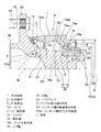
この発明の第1の実施形態を図1ないし図3と共に説明する。この実施形態は、第3世代型の内輪回転タイプで、かつ従動輪支持用の車輪用軸受装置に適用したものである。なお、この明細書において、車両に取付けた状態で車両の車幅方向外側寄りとなる側をアウトボード側と言い、車両の中央寄りとなる側をインボード側と呼ぶ。 A first embodiment of the present invention will be described with reference to FIGS. This embodiment is a third generation inner ring rotating type and is applied to a wheel bearing device for supporting a driven wheel. In this specification, the side closer to the outer side in the vehicle width direction of the vehicle when attached to the vehicle is referred to as the outboard side, and the side closer to the center of the vehicle is referred to as the inboard side.
この車輪用軸受装置は、内周に複列の軌道面3,4を形成した外方部材1と、これら各軌道面3,4に対向する軌道面5,6を外周に形成した内方部材2と、これら外方部材1および内方部材2の対向する軌道面3,5間および軌道面4,6間に介在した複列のボー
ル7,8とで構成される。この車輪用軸受装置は、複列のアンギュラ玉軸受型とされていて、ボール7,8はボールからなり、各列毎に保持器9,10で保持されている。上記各軌道面3〜6は断面円弧状であり、これら軌道面3〜6は、接触角θが背面合わせとなるように形成されている。すなわち、各列Lo,Liの軸受部11,12がアンギュラ玉軸受とされ、背面合わせとされている。外方部材1と内方部材2との間の軸受空間におけるアウトボード側端はシール13で密閉され、インボード側端は軸受端面の全体を覆うキャップ(図示せず)により密閉される。内方部材2のインボード側端に外周には、回転速度検出用の磁気エンコーダ14が取付けられている。
The wheel bearing device includes an outer member 1 having double-
外方部材1は、固定側の部材となるものであって、車体の懸架装置(図示せず)におけるナックル15に取付ける取付部16として、ナックル15を嵌合させるナックル嵌合部16aおよび車体固定フランジ16bが設けられている。ナックル嵌合部16aは、外方部材1のインボード側端に設けられ、車体固定フランジ16bは、ナックル嵌合部16aに隣接して設けられている。車体固定フランジ16bは、円周方向の複数箇所に部分的に設けられていて、ねじ孔からなるボルト挿通孔17を有し、ナックルに挿通された固定ボルト(図示せず)をボルト挿通孔17にねじ込むことで、ナックル15にこの車輪用軸受装置が固定される。ホルト挿通孔17をねじ孔とする代わりに、ナットを用いても良い。
ナックル嵌合部16aは、外方部材1における他の部分よりも小径とされており、このナックル嵌合部16aのある軸方向位置に外方部材1のインボード側の軌道面4が位置している。
The outer member 1 is a member on the fixed side, and as a mounting
The knuckle
内方部材2は、回転側の部材となるものであって、ハブ輪18と内輪19とでなり、ハブ輪18にアウトボード側の軌道面5が、内輪19にインボード側の軌道面6がそれぞれ形成されている。ハブ輪18は、軸部18aのアウトボード側端の外周に車輪取付用のハブフランジ20を有し、軸部18aのインボード側端の外周に段差部状に小径となる内輪嵌合面21を有している。内輪19は、ハブ輪18の内輪嵌合面21に嵌合し、ハブ輪18の加締部22によってハブ輪18に固定されている。加締部22は、ハブ輪18のインボード側端に延出させた円筒状部分を外径側へローリング加締等で加締めることで形成される。
The
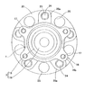
ハブフランジ20は、円周方向の複数箇所にボルト挿通孔23を有し、ボルト24がボルト挿通孔23に圧入されている。ハブフランジ20のアウトボード側の側面に、ブレーキディスクとホイール(いずれも図示せず)とが重ねられ、上記ボルト24にねじ込んだナット(図示せず)により固定される。ハブフランジ20は、全周に連続しているが、円周方向の複数箇所におけるボルト挿通孔23の周辺部が放射状に延びる厚肉部20a(図3)とされ、隣合う厚肉部20aの間の薄肉部に、軽量化のためのくり抜き孔25が設けられている。
The
ハブフランジ20のアウトボード側の側面における基端には、前記ブレーキディスクおよびホイールの内径面を案内するためのパイロット部26が突出している。パイロット部26は、ハブ輪18の正面に設けられた肉盗み用の正面凹部27の形成により、円筒状とされている。
A
両列のボール7,8の列Lo,Liの寸法関係は、アウトボード側のボール列Loのボール7のピッチ円直径PCDoを、インボード側のボール列Liのボール8のピッチ円直径PCDiよりも大きくしてあるため、アウトボード側列Loのボール7の個数を、インボード側列のボール8の個数よりも多く配置することを可能としている。例えば、アウトボード側列Loのボール個数を19個、インボード側列Liのボール個数を17個としている。両列Lo,Liの接触角θは、互いに同じとし、例えば40度としている。
The dimensional relationship between the rows Lo and Li of the
ハブ輪18の軸部18aの外周形状は、両ボール列Lo,Li間の中央位置Pにおける外径D1を、インボード側の軌道面6の溝底径である最小径D2よりも大きくしている。上記中央位置Pは、両列Lo,LiのボールスパンWの中央となる位置である。内輪19がハブ輪18の内輪嵌合面21の端部に突き合わされる位置Qは、上記中央位置Pよりもインボード側である。
図2に拡大して示すように、ハブ輪18の軸部18aの両ボール列Lo,Liの間の部分は、詳しくは、次の形状寸法とされている。アウトボード側の軌道面5は、ボール中心で最小径D3となって、この最小径D3の部分がボール中心よりも若干(ボール径の数分の一程度)インボード側に延びている。ハブ輪軸部18aの外径面は、軌道面5のインボード側に隣接する部分が、インボード側へ小径となる断面円弧状の第1の径変化部分18aaとされ、この径変化部分18aaから外径一定の直軸部分18abに続き、直軸部分18abからインボード側が小径となるテーパ状の第2の径変化部分18acを介して、前記段差部状の内輪嵌合面21に続いている。直軸部分18abの外径が、上記中央位置Pにおける外径D1となる。
The outer peripheral shape of the
As shown in FIG. 2 in an enlarged manner, the portion between the ball rows Lo and Li of the
第1の径変化部分18aaの断面の円弧状曲線における曲率半径R1は、軌道面5の断面の曲率半径よりも大きくされ、例えば2倍程度の寸方とされている。寸法例で示すと、軌道面5の溝曲率半径が10mmである場合、径変化部分18aaの曲率半径R1は20mm程度とされる。
内輪19は、軌道面6よりもアウトボード側の部分が、軌道面6の溝底径である最小径D2よりもさらに小径となる小径化部19aとされ、ハブ輪18の内輪嵌合面21の端面の外径、つまり第2の径変化部分18acの最小径は、内輪小径化部19aの端部の径と略同じ寸法とされている。なお、内輪小径化部19aは、必ずしも設けなくても良いが、その場合でも、ハブ輪19の直軸部分18abの外径D1は、内輪19の最小径D2よりも大きくされる。
The radius of curvature R1 in the arc-shaped curve of the cross section of the first diameter changing portion 18aa is larger than the radius of curvature of the cross section of the
The
ハブ輪18における前記正面凹部27の深さは、ハブ輪18側のボール7の中心の軸方向位置Aよりも深いものとされている。この正面凹部27の深さは、この実施形態では、ハブ輪軸部18aの第1の径変化部分18aaの最小径部の付近、つまり直軸部分18abの端部付近までの深さとされている。正面凹部27の断面形状は、底側へ次第に小径となる形状とされ、また接触角θを成す直線Mの付近が、正面凹部27の内側へ盛り上がる盛り上がり部27aとなる形状とされている。
The depth of the
外方部材の内径面における両列Lo,Liの軌道面3,4の間には、円周溝からなる肉盗み部28が設けられている。肉盗み部28は、両軌道面3,4の間の軸方向寸法の半分程度の軸方向幅とされ、その深さは、アウトボード側の軌道面3の溝底と同程度とされている。
A
インボード側列Liの寸法関係を説明すると、ボール列Liのピッチ円直径PCDiに対するボール径(ボールの直径)dの割合(d/PCDi)を、
0.14≦(d/PCDi)≦0.25
としている。
The dimensional relationship of the inboard side row Li will be described. The ratio (d / PCDi) of the ball diameter (ball diameter) d to the pitch circle diameter PCDi of the ball row Li is
0.14 ≦ (d / PCDi) ≦ 0.25
It is said.
また、外方部材1のナックル嵌合部16aの外径Dに対するインボード側ボール列Liのピッチ円直径PCDiの割合(PCDi/D)を、
0.66≦(PCDi/D)≦0.80
としている。
Further, the ratio (PCDi / D) of the pitch circle diameter PCDi of the inboard side ball row Li to the outer diameter D of the knuckle
0.66 ≦ (PCDi / D) ≦ 0.80
It is said.
さらに、インボード側列Liについては、外方部材1のインボード側の軌道面4の内径D4を、ナックル嵌合部16aと軌道面4間の肉厚tとして必要肉厚が得られる範囲で最大径とし、インボード側列Liのボール8を、所定の転動疲労寿命が得られる最小径としている。肉厚tの最小必要肉厚は、小型車から大型車に渡り、一般乗用車の車輪用軸受装置では、ナックル嵌合部16aの外径Dにかかわらず、例えば4mm程度である。
外方部材1は、両列Lo,Liの軌道面3,4およびナックル嵌合部16aが焼入れ処理されていて、これらの焼入れ処理の必要上からも、上記肉厚tの最小肉厚が定まる。
Further, for the inboard side row Li, the inner thickness D4 of the raceway surface 4 on the inboard side of the outer member 1 is within a range in which the required thickness can be obtained as the thickness t between the knuckle
In the outer member 1, the raceway surfaces 3 and 4 of both rows Lo and Li and the knuckle
この構成の車輪用軸受装置によると、アウトボード側列Loのピッチ円直径PCDoをインボード側列Liのピッチ円直径PCDiよりも大きくしたため、アウトボード側部分の軸受剛性が向上する。ボール7,8の個数についても、アウトボード側列Loの個数を多くしたため、アウトボード側部分の軸受剛性がより一層向上する。
According to the wheel bearing device of this configuration, since the pitch circle diameter PCDo of the outboard side row Lo is made larger than the pitch circle diameter PCDi of the inboard side row Li, the bearing rigidity of the outboard side portion is improved. As for the number of
このようにアウトボード側の剛性を向上させた上で、インボード側のボール列Liのピッチ円直径PCDiに対するボール径dの割合(d/PCDi)を、
0.14≦(d/PCDi)≦0.25
としたため、インボード側における剛性の向上、転動疲労寿命の確保が得られる。
Thus, after improving the rigidity on the outboard side, the ratio (d / PCDi) of the ball diameter d to the pitch circle diameter PCDi of the ball row Li on the inboard side is
0.14 ≦ (d / PCDi) ≦ 0.25
Therefore, improvement in rigidity on the inboard side and securing of a rolling fatigue life can be obtained.
すなわち、ピッチ円直径PCDiが同じである場合、ボール径dを小さくしてボール個数を増やすことにより、支持点が増加して軸受剛性が高くなる。剛性向上の点からは、ボール径が小さいほど好ましい。しかし、ボール径が小さくなるに従い、転動疲労寿命が低下する。ピッチ円直径PCDiとボール径dの関係をFEM解析(有限要素法による解析)による求めた結果、d/PCDiが0.2よりも大きいと、車輪用軸受装置として剛性の向上にならず、またd/PCDiが0.14未満であると、車輪用軸受装置として転動疲労寿命が不足することが分かった。
0.14≦(d/PCDi)≦0.25の範囲とすることで、剛性の向上の図りながら転動疲労寿命を確保することができる。
なお、軸受サイズによっては、d/PCDiの値が上記範囲内のものでも剛性が上がらないものもあるが、当該範囲であれば軸受サイズを適宜選択することによって剛性アップを図ることができる。
That is, when the pitch circle diameter PCDi is the same, the support point is increased and the bearing rigidity is increased by decreasing the ball diameter d and increasing the number of balls. From the viewpoint of improving rigidity, the smaller the ball diameter, the better. However, as the ball diameter decreases, the rolling fatigue life decreases. As a result of obtaining the relationship between the pitch circle diameter PCDi and the ball diameter d by FEM analysis (analysis by the finite element method), if d / PCDi is larger than 0.2, the rigidity of the wheel bearing device is not improved. It was found that when d / PCDi is less than 0.14, the rolling fatigue life is insufficient as a wheel bearing device.
By making the range 0.14 ≦ (d / PCDi) ≦ 0.25, the rolling fatigue life can be secured while improving the rigidity.
Note that, depending on the bearing size, there is a case where the rigidity does not increase even if the value of d / PCDi is within the above range, but if it is within this range, the rigidity can be increased by appropriately selecting the bearing size.
従来の車輪用軸受装置は、PCDiに対してボール径が大きく、転動疲労寿命の点で余裕のある設計となっており、剛性が不足している。この実施形態は、このような従来の問題を解消し、剛性と転動疲労寿命の関係の最適化を図るものである。
アウトボード側については、PCDを大きくしてあるため、d/PCDの値はインボード側よりも小さくなる。しかしアウトボード側は、PCDが大きくなる分、余裕があり、必要な転動疲労寿命が確保される。
A conventional wheel bearing device has a larger ball diameter than PCDi, has a design with a margin in terms of rolling fatigue life, and lacks rigidity. This embodiment solves such a conventional problem and aims to optimize the relationship between rigidity and rolling fatigue life.
Since the PCD is increased on the outboard side, the value of d / PCD is smaller than that on the inboard side. However, on the outboard side, there is a margin as the PCD increases, and the necessary rolling fatigue life is ensured.
また、この実施形態では、外方部材1のナックル嵌合部16aの外径Dに対するインボ
ード側のボール列Liのピッチ円直径PCDiの割合(PCDi/D)を、
0.66≦(PCDi/D)≦0.80
としたため、インボード側における剛性の向上、転動疲労寿命の確保が得られる。
In this embodiment, the ratio (PCDi / D) of the pitch circle diameter PCDi of the ball row Li on the inboard side to the outer diameter D of the knuckle
0.66 ≦ (PCDi / D) ≦ 0.80
Therefore, improvement in rigidity on the inboard side and securing of a rolling fatigue life can be obtained.
すなわち、外方部材1のナックル嵌合部16aの外径Dは、軸受設計上で要求寸法として定まった値となる。そのため、このナックル嵌合部外径Dに対して、剛性の向上、転動疲労寿命の確保を図ることが必要となる。
上記ピッチ円直径PCDiは、インボード側の軌道面4の内径D4からボール径dを差し引いた値であり、ボール径dが小さいほど、ボール中心が軌道面4の内面に近づき、PCDiの値が軌道面内径D4の値に近づくことになる。ここで、インボード側軌道面4はナックル嵌合部16aの内周に位置するため、ナックル嵌合部16aの外径Dが一定であ
って、外方部材1における軌道面外周の肉厚tにつき必要最低肉厚を確保できる範囲で可能な限り大きな値すると、軌道面内径D4は、D4=D−2×tであり、一定の値となる。上記のように肉厚tの必要最低厚さは、例えば4mm程度となる。
軌道面内径D4が一定であると、PCDi(=D4−d)の値は、ボール径dに依存することになる。ナックル嵌合部外径Dも一定と考えると、PCDi/Dの値は、ボール径dに依存することになり、ボール径が小さいほど、PCDi/Dの値が大きくなる。
ボール径dを小さくした場合、ボール個数を増やすことができて、それだけ支持点が増加するため、軸受剛性が高くなる。そのため剛性向上の点からは、ボール径が小さいほど好ましい。
ナックル嵌合部外径Dが一定であり、軌道面外周の必要肉厚tが一定であるとして、つまり軌道面内径D4が一定であるとして、PCDi/Dの変化による剛性,転動疲労寿命の関係をFEM解析により求めた。その結果、PCDi/Dが0.66未満であると、車輪用軸受装置として剛性の向上にならず、またPCDi/Dが0.80よりも大きいと、車輪用軸受装置として転動疲労寿命が不足することが分かった。
0.66≦(PCDi/D)≦0.80
の範囲とすることで、剛性の向上の図りながら転動疲労寿命を確保することができる。
That is, the outer diameter D of the knuckle
The pitch circle diameter PCDi is a value obtained by subtracting the ball diameter d from the inner diameter D4 of the track surface 4 on the inboard side. The smaller the ball diameter d, the closer the ball center is to the inner surface of the track surface 4, and the value of PCDi is It approaches the value of the raceway inner diameter D4. Here, since the inboard side raceway surface 4 is located on the inner circumference of the knuckle
When the raceway inner diameter D4 is constant, the value of PCDi (= D4-d) depends on the ball diameter d. Assuming that the knuckle fitting outer diameter D is also constant, the PCDi / D value depends on the ball diameter d, and the smaller the ball diameter, the larger the PCDi / D value.
When the ball diameter d is reduced, the number of balls can be increased and the support points are increased accordingly, so that the bearing rigidity is increased. Therefore, the smaller the ball diameter, the better from the viewpoint of improving the rigidity.
Assuming that the outer diameter D of the knuckle fitting portion is constant and the required wall thickness t on the outer periphery of the raceway surface is constant, that is, the inner diameter D4 of the raceway surface is constant, the rigidity and rolling fatigue life due to changes in PCDi / D The relationship was determined by FEM analysis. As a result, if PCDi / D is less than 0.66, the rigidity of the wheel bearing device is not improved, and if PCDi / D is greater than 0.80, the rolling fatigue life of the wheel bearing device is reduced. I found out that it was insufficient.
0.66 ≦ (PCDi / D) ≦ 0.80
By making it into this range, the rolling fatigue life can be ensured while improving the rigidity.
インボード側につき、PCDi/Dの値と剛性との関係を検討すると、図5に示す結果が得られた。剛性はJIS B1519に記載された基本静定格荷重から導き出されるものです。
同図によると、PCDi/Dの値が0.66〜0.80の範囲では、剛性がほぼ一定であるが、0.66未満になる付近で剛性が急に低下し、PCDi/Dがさらに小さくなっても、剛性は低下した値で一定になっている。これより、PCDi/Dの値が0.66未満になると、剛性アップにはならないことがわかる。PCDi/Dの値が0.80を超える場合は、剛性の点では問題がないが、上述のように転動疲労寿命が確保できず、好ましくない。
なお、軸受サイズによっては、PCDi/Dの値が上記範囲内のものでも剛性が上がらないものもあるが、当該範囲であれば軸受サイズを適宜選択することによって剛性アップを図ることができる。
When the relationship between the PCDi / D value and the rigidity was examined on the inboard side, the result shown in FIG. 5 was obtained. The rigidity is derived from the basic static load rating described in JIS B1519.
According to the figure, the rigidity is almost constant in the range of PCDi / D in the range of 0.66 to 0.80, but the rigidity suddenly decreases near 0.66 and PCDi / D further increases. Even if it becomes smaller, the rigidity remains constant at a reduced value. From this, it can be seen that when the PCDi / D value is less than 0.66, the rigidity is not increased. When the value of PCDi / D exceeds 0.80, there is no problem in terms of rigidity, but the rolling fatigue life cannot be ensured as described above, which is not preferable.
Depending on the bearing size, even if the PCDi / D value is within the above range, the rigidity does not increase. However, within this range, the rigidity can be increased by appropriately selecting the bearing size.
従来の車輪用軸受装置は、ナックル嵌合部外径Dに対してボール径が大きく、転動疲労寿命の点で余裕のある設計となっており、剛性が不足している。この実施形態は、このような従来の問題を解消し、剛性と転動疲労寿命の関係の最適化を図るものである。 The conventional wheel bearing device has a large ball diameter with respect to the outer diameter D of the knuckle fitting portion, has a design with a margin in terms of rolling fatigue life, and lacks rigidity. This embodiment solves such a conventional problem and aims to optimize the relationship between rigidity and rolling fatigue life.
また、この実施形態では、さらに次のようにアウトボード側の剛性向上が達成される。すなわち、両ボール列Lo,Li間の中央位置Pにおけるハブ輪18の外径D1を、インボード側列Liの軌道面6の最小径D2よりも大きくしたため、軸受装置に作用する車両走行時のモーメント荷重に対して、ハブ輪18の剛性を高めることができる。従来の軸受装置は、いずれも両ボール列間のハブ輪外径が、インボード側列の軌道面の溝底径に合わ
されているが、この部分のハブ輪外径D1を大きくすることが、剛性向上に大きく寄与
する。軸受装置における各部の大径化や厚肉化は、剛性増につながるが、FEM解析(有限要素法による解析)の結果、両ボール列Lo,Liの間のハブ輪18の外径を増加することが、上記モーメント荷重に対する剛性向上に効率的であることが分かった。したがって、この部分の外径D1を増大させることで、軸受装置の他の部分の肉を削り、重量増加を伴うことなく、剛性向上を達成することができる。
In this embodiment, the rigidity on the outboard side is further improved as follows. That is, since the outer diameter D1 of the
軸受装置の肉を削る構成としては、外方部材1の内径面における両列Lo,Liの軌道面3,4の間に、円周溝からなる肉盗み部28を設けている。
解析によると、外方部材1の内径面における両列Lo,Liの軌道面3,4の間の部分は、軸受剛性に対する影響が小さく、上記肉盗み部28を内径面に設けても、剛性低下へ
の影響が殆どない。したがって、ハブ輪1の両ボール列Lo,Li間の中間の外径D1を大きくし、外方部材1に上記肉盗み部28を設けることで、重量増加を伴うことなく、アウトボード側の軸受剛性を高めることができる。
As a configuration for cutting the meat of the bearing device, a
According to the analysis, the portion between the raceway surfaces 3 and 4 of both rows Lo and Li on the inner diameter surface of the outer member 1 has little influence on the bearing rigidity. Even if the
また、この実施形態では、アウトボード側列Loのピッチ円直径PCDoを大きくしたため、これに伴い、上記のように両ボール列Lo,Li間の中央位置Pにおけるハブ輪外径D1を大きくする設計が容易となる。すなわち、ハブ輪18の両ボール列Lo,Li間の部分を、インボード側列Liの軌道面6の溝底径D2よりも大きくしても、アウトボード側列Loの軌道面溝底径D3よりは小さくできるため、アウトボード側列Loであるバブ輪軌道面5へのボール7の組み込み性を阻害することがない。
In this embodiment, since the pitch circle diameter PCDo of the outboard side row Lo is increased, the hub wheel outer diameter D1 at the center position P between the ball rows Lo and Li is increased as described above. Becomes easy. That is, even if the portion between both the ball rows Lo and Li of the
ハブ輪18の軸受部18aの外径面形状については、ハブ輪18の軌道面5のインボード側に隣接する部分を、軌道面5の最小径D3よりも小径となる径変化部分18aaとしているため、ハブ輪18の外径が小さくなることで、ハブ輪18が軽量化される。この場合に、急激な外径変化があると、ハブ輪18のアウトボード側部分の剛性低下を招くが、次第に小径となる断面円弧状の径変化部分18aaとし、断面の曲率半径R1を軌道面5の曲率半径よりも大きくしたため、ハブ輪18のアウトボード側部分の剛性を高めながら、重量増を回避することができる。
Regarding the outer diameter surface shape of the bearing
また、ハブ輪18のアウトボード側の端面に設けられる正面凹部27を、ハブ輪18側のボール7の中心の軸方向位置Aよりも深くしたため、正面凹部27により肉を盗む量を多くできて、より軽量化することができる。正面凹部27を設けても、ハブ輪18の剛性低下への影響は小さく、この実施形態のようにハブ輪18の両ボール列Lo,Li間の中間の外径D1を大きくした場合は、正面凹部27を上記のように深くしても、剛性が確保できる。これによっても、重量増加を抑えながら、アウトボード側の軸受剛性を高めることができる。正面凹部27の形状は、この例では、接触角θを成す直線Mの付近が、正面凹部27の内側へ盛り上がる盛り上がり部27aとなる形状とされているため、正面凹部27の内径をできるだけ大きくしてより軽量化を進めながら、必要な剛性を確保することができる。
Further, since the front
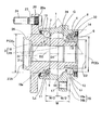
図6は、この発明の他の実施形態を示す。この実施形態は、第3世代型の内輪回転タイプで、駆動輪支持用の車輪用軸受装置に適用したものである。この車輪用軸受装置は、図1ないし図3と共に説明した第1の実施形態において、内方部材2におけるハブ輪18の中心部に駆動軸結合孔31を貫通して設けたものである。駆動軸結合孔31は、等速ジョイント(図示せず)の一方の継手部材となる外輪のステム部を貫通させる孔であり、内径面に、上記ステム部のスプラインと噛み合うスプライン溝31aが形成されている。正面凹部27Aは、上記ステム部の先端の雄ねじ部分にねじ込むナット(図示せず)が収められる座ぐり部として設けられている。内輪19のハブ輪18への固定は、上記ナットの締め付けにより、等速ジョイント外輪の一部を内輪19の幅面に押し付けることで行われる。また、外方部材1と内方部材2との間の軸受空間におけるインボード側端はシール32で密閉され、上記磁気エンコーダ14が、シール32におけるスリンガを兼用している。この実施形態におけるその他の構成は、第1の実施形態と同様である。
このように駆動輪支持用の車輪用軸受装置に適用した場合も、上記実施形態と同様に、軸受重量の増加を抑えながら、アウトボード側部分の剛性を高めることのできるなどの各効果が得られる。
FIG. 6 shows another embodiment of the present invention. This embodiment is a third generation type inner ring rotating type, and is applied to a wheel bearing device for driving wheel support. In the wheel bearing device according to the first embodiment described with reference to FIGS. 1 to 3, a drive
When applied to a wheel bearing device for driving wheel support in this way, each effect such as increasing the rigidity of the outboard side portion while suppressing an increase in bearing weight can be obtained as in the above embodiment. It is done.
1…外方部材
2…内方部材
3〜6…軌道面
7,8…ボール
11,12…軸受部
15…ナックル
16…取付部
16a…ナックル嵌合部
18…ハブ輪
18a…ハブ輪の軸部
18aa…径変化部分
18ab…直軸部分
19…内輪
20…ハブフランジ
27…正面凹部
28…肉盗み部
D…ナックル嵌合部の外径
D4…インボード側の軌道面の内径
PCDi…インボード側のピッチ円直径
PCDo…アウトボード側のピッチ円直径
t…肉厚
DESCRIPTION OF SYMBOLS 1 ...
Claims (3)
アウトボード側のボール列のピッチ円直径を、インボード側のボール列のピッチ円直径よりも大きくし、アウトボード側列のボール個数をインボード側列のボール個数よりも多くし、
前記外方部材の前記ナックル嵌合部の外径Dに対するインボード側のボール列のピッチ円直径PCDiの割合(PCDi/D)を、
0.66≦(PCDi/D)≦0.80
としたことを特徴とする車輪用軸受装置。 A knuckle fitting portion for fitting a knuckle in a suspension device of a vehicle body is fitted on the outer periphery of the inboard side end, and a double row raceway surface is provided on the inner circumference, and the whole or part of the inboard side raceway surface is the knuckle. An outer member that overlaps the axial range where the fitting portion is provided, a double row raceway surface facing each raceway surface on the outer periphery, and a hub flange for wheel mounting on the outer periphery of the outboard side end In a wheel bearing device comprising a side member and a ball interposed between opposing raceway surfaces,
The pitch circle diameter of the ball row on the outboard side is larger than the pitch circle diameter of the ball row on the inboard side, the number of balls on the outboard side row is larger than the number of balls on the inboard side row,
The ratio (PCDi / D) of the pitch circle diameter PCDi of the ball row on the inboard side to the outer diameter D of the knuckle fitting portion of the outer member,
0.66 ≦ (PCDi / D) ≦ 0.80
A wheel bearing device characterized by that.
前記外方部材のインボード側の軌道面の内径を、前記ナックル嵌合部とこの軌道面間の必要肉厚が得られる最大径とし、インボード側列のボールを、所定の転動疲労寿命が得られる最小径とし、
アウトボード側のボール列のピッチ円直径を、インボード側のボール列のピッチ円直径よりも大きくし、アウトボード側列のボール個数をインボード側列のボール個数よりも多くしたことを特徴とする車輪用軸受装置。 A knuckle fitting portion for fitting a knuckle in a suspension device of a vehicle body is fitted on the outer periphery of the inboard side end, and a double row raceway surface is provided on the inner circumference, and the whole or part of the inboard side raceway surface is the knuckle. An outer member that overlaps the axial range where the fitting portion is provided, a double row raceway surface facing each raceway surface on the outer periphery, and a hub flange for wheel mounting on the outer periphery of the outboard side end In a wheel bearing device comprising a side member and a ball interposed between opposing raceway surfaces,
The inner diameter of the raceway surface on the inboard side of the outer member is set to the maximum diameter at which the necessary thickness between the knuckle fitting portion and the raceway surface can be obtained, and the balls in the inboard side row have a predetermined rolling fatigue life. Is the smallest diameter that can be obtained,
The pitch circle diameter of the ball row on the outboard side is larger than the pitch circle diameter of the ball row on the inboard side, and the number of balls in the outboard side row is larger than the number of balls in the inboard side row. Wheel bearing device.
Priority Applications (1)
| Application Number | Priority Date | Filing Date | Title |
|---|---|---|---|
| JP2007031599A JP2007132526A (en) | 2007-02-13 | 2007-02-13 | Bearing device for wheel |
Applications Claiming Priority (1)
| Application Number | Priority Date | Filing Date | Title |
|---|---|---|---|
| JP2007031599A JP2007132526A (en) | 2007-02-13 | 2007-02-13 | Bearing device for wheel |
Related Parent Applications (1)
| Application Number | Title | Priority Date | Filing Date |
|---|---|---|---|
| JP2006206097A Division JP3974156B2 (en) | 2006-07-28 | 2006-07-28 | Wheel bearing device |
Publications (2)
| Publication Number | Publication Date |
|---|---|
| JP2007132526A true JP2007132526A (en) | 2007-05-31 |
| JP2007132526A5 JP2007132526A5 (en) | 2008-06-26 |
Family
ID=38154340
Family Applications (1)
| Application Number | Title | Priority Date | Filing Date |
|---|---|---|---|
| JP2007031599A Pending JP2007132526A (en) | 2007-02-13 | 2007-02-13 | Bearing device for wheel |
Country Status (1)
| Country | Link |
|---|---|
| JP (1) | JP2007132526A (en) |
Cited By (3)
| Publication number | Priority date | Publication date | Assignee | Title |
|---|---|---|---|---|
| JP2008296852A (en) * | 2007-06-04 | 2008-12-11 | Ntn Corp | Wheel bearing device |
| KR101424729B1 (en) | 2013-04-09 | 2014-08-04 | 주식회사 에스비비테크 | Double row bearing assembly |
| JP2018039428A (en) * | 2016-09-08 | 2018-03-15 | Ntn株式会社 | Bearing device for vehicle |
Citations (10)
| Publication number | Priority date | Publication date | Assignee | Title |
|---|---|---|---|---|
| JPS5359202U (en) * | 1976-10-20 | 1978-05-20 | ||
| JP2000006609A (en) * | 1998-06-25 | 2000-01-11 | Isuzu Motors Ltd | Vehicular tire supporting structure |
| JP2001213111A (en) * | 2000-02-03 | 2001-08-07 | Ntn Corp | Bearing device for wheel |
| WO2003069175A1 (en) * | 2002-02-12 | 2003-08-21 | Nsk Ltd. | Pulley bearing for engine auxiliaries |
| JP2003307229A (en) * | 2002-04-12 | 2003-10-31 | Nsk Ltd | Bearing with built-in pulse forming ring and hub unit bearing |
| WO2004007983A1 (en) * | 2002-07-12 | 2004-01-22 | Nsk Ltd. | Pulley support double row ball bearing |
| JP2004108449A (en) * | 2002-09-17 | 2004-04-08 | Koyo Seiko Co Ltd | Rolling bearing device |
| JP2004345439A (en) * | 2003-05-21 | 2004-12-09 | Honda Motor Co Ltd | Wheel supporting hub unit |
| JP2005076660A (en) * | 2003-08-29 | 2005-03-24 | Nsk Ltd | Anti-friction bearing device |
| JP2005076874A (en) * | 2003-09-03 | 2005-03-24 | Nsk Ltd | Hub unit bearing |
-
2007
- 2007-02-13 JP JP2007031599A patent/JP2007132526A/en active Pending
Patent Citations (10)
| Publication number | Priority date | Publication date | Assignee | Title |
|---|---|---|---|---|
| JPS5359202U (en) * | 1976-10-20 | 1978-05-20 | ||
| JP2000006609A (en) * | 1998-06-25 | 2000-01-11 | Isuzu Motors Ltd | Vehicular tire supporting structure |
| JP2001213111A (en) * | 2000-02-03 | 2001-08-07 | Ntn Corp | Bearing device for wheel |
| WO2003069175A1 (en) * | 2002-02-12 | 2003-08-21 | Nsk Ltd. | Pulley bearing for engine auxiliaries |
| JP2003307229A (en) * | 2002-04-12 | 2003-10-31 | Nsk Ltd | Bearing with built-in pulse forming ring and hub unit bearing |
| WO2004007983A1 (en) * | 2002-07-12 | 2004-01-22 | Nsk Ltd. | Pulley support double row ball bearing |
| JP2004108449A (en) * | 2002-09-17 | 2004-04-08 | Koyo Seiko Co Ltd | Rolling bearing device |
| JP2004345439A (en) * | 2003-05-21 | 2004-12-09 | Honda Motor Co Ltd | Wheel supporting hub unit |
| JP2005076660A (en) * | 2003-08-29 | 2005-03-24 | Nsk Ltd | Anti-friction bearing device |
| JP2005076874A (en) * | 2003-09-03 | 2005-03-24 | Nsk Ltd | Hub unit bearing |
Cited By (3)
| Publication number | Priority date | Publication date | Assignee | Title |
|---|---|---|---|---|
| JP2008296852A (en) * | 2007-06-04 | 2008-12-11 | Ntn Corp | Wheel bearing device |
| KR101424729B1 (en) | 2013-04-09 | 2014-08-04 | 주식회사 에스비비테크 | Double row bearing assembly |
| JP2018039428A (en) * | 2016-09-08 | 2018-03-15 | Ntn株式会社 | Bearing device for vehicle |
Similar Documents
| Publication | Publication Date | Title |
|---|---|---|
| JP5242957B2 (en) | Wheel bearing device | |
| JP3970890B2 (en) | Wheel bearing device | |
| JP5570297B2 (en) | Wheel bearing device | |
| JP2008121839A (en) | Bearing device for wheel | |
| JP2008055984A (en) | Bearing device for wheel | |
| US20040096133A1 (en) | Vehicle-use bearing apparatus | |
| JP2008100632A (en) | Bearing device for wheel | |
| CN107405951B (en) | Wheel bearing device | |
| JP4823269B2 (en) | Wheel bearing device | |
| JP2006316904A (en) | Bearing device for wheel | |
| JP2007132526A (en) | Bearing device for wheel | |
| JP2007132526A5 (en) | ||
| JP6366233B2 (en) | Wheel bearing device | |
| JP4877815B2 (en) | Wheel bearing device | |
| JP3974156B2 (en) | Wheel bearing device | |
| JP2006316905A (en) | Bearing device for wheel | |
| JP2005119505A (en) | Bearing device for wheel | |
| JP2007211989A5 (en) | ||
| JP2007269285A (en) | Hub unit | |
| JP2007100715A (en) | Bearing device for vehicle | |
| JP2006317007A (en) | Bearing device for wheel | |
| JP2005140192A (en) | Bearing device for wheel | |
| JP2005297925A (en) | Bearing device for wheel | |
| JP5024850B2 (en) | Wheel bearing device | |
| JP2008296621A (en) | Wheel bearing device |
Legal Events
| Date | Code | Title | Description |
|---|---|---|---|
| A521 | Written amendment |
Free format text: JAPANESE INTERMEDIATE CODE: A523 Effective date: 20080512 |
|
| A621 | Written request for application examination |
Free format text: JAPANESE INTERMEDIATE CODE: A621 Effective date: 20080512 |
|
| A131 | Notification of reasons for refusal |
Free format text: JAPANESE INTERMEDIATE CODE: A131 Effective date: 20110118 |
|
| A977 | Report on retrieval |
Free format text: JAPANESE INTERMEDIATE CODE: A971007 Effective date: 20110120 |
|
| A02 | Decision of refusal |
Free format text: JAPANESE INTERMEDIATE CODE: A02 Effective date: 20110802 |