JP2005297925A - Bearing device for wheel - Google Patents
Bearing device for wheel Download PDFInfo
- Publication number
- JP2005297925A JP2005297925A JP2004121016A JP2004121016A JP2005297925A JP 2005297925 A JP2005297925 A JP 2005297925A JP 2004121016 A JP2004121016 A JP 2004121016A JP 2004121016 A JP2004121016 A JP 2004121016A JP 2005297925 A JP2005297925 A JP 2005297925A
- Authority
- JP
- Japan
- Prior art keywords
- wheel
- hub
- bolt insertion
- bearing device
- pilot
- Prior art date
- Legal status (The legal status is an assumption and is not a legal conclusion. Google has not performed a legal analysis and makes no representation as to the accuracy of the status listed.)
- Pending
Links
- 238000005096 rolling process Methods 0.000 claims abstract description 53
- 238000003780 insertion Methods 0.000 claims description 49
- 230000037431 insertion Effects 0.000 claims description 49
- 230000015572 biosynthetic process Effects 0.000 claims description 3
- 238000005520 cutting process Methods 0.000 claims description 2
- 238000005452 bending Methods 0.000 abstract description 5
- 238000010276 construction Methods 0.000 abstract 1
- 239000013585 weight reducing agent Substances 0.000 description 17
- 238000005242 forging Methods 0.000 description 15
- 239000000463 material Substances 0.000 description 4
- 239000000725 suspension Substances 0.000 description 4
- 229910052799 carbon Inorganic materials 0.000 description 3
- 230000006698 induction Effects 0.000 description 3
- 238000000034 method Methods 0.000 description 3
- OKTJSMMVPCPJKN-UHFFFAOYSA-N Carbon Chemical compound [C] OKTJSMMVPCPJKN-UHFFFAOYSA-N 0.000 description 2
- 229910000954 Medium-carbon steel Inorganic materials 0.000 description 2
- 230000001771 impaired effect Effects 0.000 description 2
- 238000010348 incorporation Methods 0.000 description 2
- 238000012986 modification Methods 0.000 description 2
- 230000004048 modification Effects 0.000 description 2
- 230000002093 peripheral effect Effects 0.000 description 2
- 230000036316 preload Effects 0.000 description 2
- 102220097517 rs876659265 Human genes 0.000 description 2
- -1 S53C Chemical compound 0.000 description 1
- 229910000831 Steel Inorganic materials 0.000 description 1
- 230000005540 biological transmission Effects 0.000 description 1
- 230000008094 contradictory effect Effects 0.000 description 1
- 238000002788 crimping Methods 0.000 description 1
- 239000000428 dust Substances 0.000 description 1
- 239000000446 fuel Substances 0.000 description 1
- 239000004519 grease Substances 0.000 description 1
- 238000010438 heat treatment Methods 0.000 description 1
- 230000001050 lubricating effect Effects 0.000 description 1
- 238000012545 processing Methods 0.000 description 1
- 238000010791 quenching Methods 0.000 description 1
- 230000000171 quenching effect Effects 0.000 description 1
- 238000012552 review Methods 0.000 description 1
- 239000010959 steel Substances 0.000 description 1
Images


Classifications
-
- F—MECHANICAL ENGINEERING; LIGHTING; HEATING; WEAPONS; BLASTING
- F16—ENGINEERING ELEMENTS AND UNITS; GENERAL MEASURES FOR PRODUCING AND MAINTAINING EFFECTIVE FUNCTIONING OF MACHINES OR INSTALLATIONS; THERMAL INSULATION IN GENERAL
- F16C—SHAFTS; FLEXIBLE SHAFTS; ELEMENTS OR CRANKSHAFT MECHANISMS; ROTARY BODIES OTHER THAN GEARING ELEMENTS; BEARINGS
- F16C19/00—Bearings with rolling contact, for exclusively rotary movement
- F16C19/02—Bearings with rolling contact, for exclusively rotary movement with bearing balls essentially of the same size in one or more circular rows
- F16C19/14—Bearings with rolling contact, for exclusively rotary movement with bearing balls essentially of the same size in one or more circular rows for both radial and axial load
- F16C19/18—Bearings with rolling contact, for exclusively rotary movement with bearing balls essentially of the same size in one or more circular rows for both radial and axial load with two or more rows of balls
- F16C19/181—Bearings with rolling contact, for exclusively rotary movement with bearing balls essentially of the same size in one or more circular rows for both radial and axial load with two or more rows of balls with angular contact
- F16C19/183—Bearings with rolling contact, for exclusively rotary movement with bearing balls essentially of the same size in one or more circular rows for both radial and axial load with two or more rows of balls with angular contact with two rows at opposite angles
- F16C19/184—Bearings with rolling contact, for exclusively rotary movement with bearing balls essentially of the same size in one or more circular rows for both radial and axial load with two or more rows of balls with angular contact with two rows at opposite angles in O-arrangement
- F16C19/186—Bearings with rolling contact, for exclusively rotary movement with bearing balls essentially of the same size in one or more circular rows for both radial and axial load with two or more rows of balls with angular contact with two rows at opposite angles in O-arrangement with three raceways provided integrally on parts other than race rings, e.g. third generation hubs
-
- F—MECHANICAL ENGINEERING; LIGHTING; HEATING; WEAPONS; BLASTING
- F16—ENGINEERING ELEMENTS AND UNITS; GENERAL MEASURES FOR PRODUCING AND MAINTAINING EFFECTIVE FUNCTIONING OF MACHINES OR INSTALLATIONS; THERMAL INSULATION IN GENERAL
- F16C—SHAFTS; FLEXIBLE SHAFTS; ELEMENTS OR CRANKSHAFT MECHANISMS; ROTARY BODIES OTHER THAN GEARING ELEMENTS; BEARINGS
- F16C2326/00—Articles relating to transporting
- F16C2326/01—Parts of vehicles in general
- F16C2326/02—Wheel hubs or castors
Landscapes
- Engineering & Computer Science (AREA)
- General Engineering & Computer Science (AREA)
- Mechanical Engineering (AREA)
- Braking Arrangements (AREA)
Abstract
Description
本発明は、自動車等の車輪を懸架装置に対して回転自在に支承する車輪用軸受装置、特に、装置の軽量・コンパクト化と共に、耐久性の向上を図った車輪用軸受装置に関するものである。 The present invention relates to a wheel bearing device that rotatably supports a wheel of an automobile or the like with respect to a suspension device, and more particularly to a wheel bearing device that is lighter and more compact and has improved durability.
近年、省資源あるいは公害等の面から燃費向上に対する要求は厳しいものがある。自動車部品において、中でも車輪軸受装置の軽量化はこうした要求に応える要因として注目され、強く望まれて久しい。特に、自動車等の車両の中でも軽四輪あるいはスモールカーをはじめとした軽車両においては、低コスト化は言うまでもなく、この軽量化に対する要求は益々増大してきている。従来から軽量化を図った車輪用軸受装置に関する提案は種々のものがあるが、それと共に車輪を回転自在に支承する車輪用軸受装置においては、この軽量化と一面では相反する信頼性と耐久性を向上させることも重要な要因となっている。 In recent years, demands for improving fuel efficiency have been severe from the viewpoint of resource saving or pollution. In automobile parts, the weight reduction of wheel bearing devices has been attracting attention as a factor to meet such demands and has been strongly desired for a long time. In particular, among vehicles such as automobiles, light vehicles such as light four-wheel vehicles or small cars are not only cost-reduced, but demands for this weight reduction are increasing. There are various proposals related to wheel bearing devices that have been made lighter in the past. However, in the wheel bearing device that supports the wheel in a freely rotatable manner, reliability and durability contradicting this weight reduction in one aspect. Improving the performance is also an important factor.
図5は、自動車に用いられ、軽量化を図った車輪用軸受装置の一例である。この車輪用軸受装置は駆動輪側に使用される代表的な構造で、ハブ輪51と複列の転がり軸受とがユニット化して構成されている。
FIG. 5 shows an example of a wheel bearing device that is used in an automobile and is reduced in weight. This wheel bearing device has a typical structure used on the drive wheel side, and includes a
車輪用軸受装置52のハブ輪51は鍛造により形成されて中空構造をなし、図示しない車輪を取り付けるための車輪取付フランジ53を一体に有し、その外周に複列の転がり軸受52の一方の内側転走面51aと、この内側転走面51aから軸方向に延びる円筒状の小径段部51bが形成され、内周にトルク伝達用のスプライン54が形成されている。
The
前記小径段部51bには、複列の転がり軸受52の他方の内側転走面55aが外周に形成された別体の内輪55が圧入されている。そして、小径段部51bの端部を径方向外方に塑性変形させて加締部56が形成され、この加締部56によって内輪55がハブ輪51に対して軸方向に固定されている。
A separate
一方、車輪用軸受装置52を構成する外方部材57は、懸架装置を構成するナックル58に固定するための車体取付フランジ57bを一体に有し、内周に前記内側転走面51a、55aに対向する複列の外側転走面57a、57aが形成されている。このように、車輪用軸受装置52は、ハブ輪51、内輪55と外方部材57と、両転走面51a、57a、55a、57a間に転動自在に収容された複列の転動体59、59とを備えている。
On the other hand, the
ハブ輪51において、車輪取付フランジ53の円周4箇所等配にハブボルト53aが植設され、ブレーキロータ60および車輪が締結される。このハブ輪51は、図6に示すように、車輪取付フランジ53に、ハブボルト53aが固定されるボルト挿通孔61が形成され、このボルト挿通孔61の周辺を避けて、各ボルト挿通孔61間において、車輪取付フランジ53の外周にR形状の切欠き部62が形成されている。
In the
切欠き部62は、ボルト挿通孔61のピッチ円直径Aより内径側で、かつ隣接するボルト挿通孔61の中心を結ぶ弦Bにその最深部62aが近接するように形成されている。さらに、車輪取付フランジ53は、各ボルト挿通孔61の外周近傍の肉厚が薄くされた薄肉部63が形成されると共に、各ボルト挿通孔61を含んで内周側の肉厚は薄くせず、充分な曲げ剛性が得られるように通常の厚肉部64とされている。これにより、軽量化を図りながらも、車輪取付フランジ53の曲げ剛性が低下するのを防止している。
しかしながら、このような従来の車輪用軸受装置のハブ輪51において、軽量化を狙ってハブ輪51のスリム化を図りつつ車輪取付フランジ53の曲げ剛性が低下するのを防止しているものの、さらなる軽量化に対する要求を満足するには至っていない。この種のスリム化されたハブ輪51を有する従来の車輪用軸受装置であっても、その減肉量はせいぜい0.1〜0.2kg程度で、装置の総重量は1.3〜1.4kgが限界で、これ以上の軽量化は強度・耐久性に問題が生じてくる。したがって、総重量が1.0kg、さらには1.0kg以下の車輪用軸受装置は、特殊な車両以外に自動車用として未だ市場にはない。こうした市場の要求を満たすためには、既成概念に囚われず車輪取付フランジ53の形状等の抜本的な見直しをはじめ、それに付随する各部位の形状・構造を再検討する必要がある。例えば、従来のハブ輪51では、ホイールパイロット部およびブレーキパイロット部が全周に連続したものであり、さらに軽量化の余地がある。
However, in the
本発明は、このような従来の問題に鑑みてなされたもので、回転曲げ荷重の条件下での強度、耐久性を確保しつつ、軽量・コンパクト化を図った車輪用軸受装置を提供することを目的とする。
また、この発明の他の目的は、鍛造加工性を向上させて低コスト化を図ると共に、車輪等の取付精度を確保しながら、より一層の軽量化が図れる車輪用軸受装置を提供することである。
The present invention has been made in view of such conventional problems, and provides a wheel bearing device that is lightweight and compact while ensuring strength and durability under the condition of rotational bending load. With the goal.
Another object of the present invention is to provide a wheel bearing device capable of reducing the cost by improving the forging processability and further reducing the weight while ensuring the mounting accuracy of the wheel. is there.
係る目的を達成すべく、本発明のうち請求項1に記載の発明は、内周に複列の外側転走面が形成された外方部材と、アウトボード側の端部に車輪取付フランジを一体に有し、外周に軸方向に延びる円筒状の小径段部が形成されたハブ輪、およびこのハブ輪の小径段部に圧入された少なくとも一つの内輪とからなり、外周に前記複列の外側転走面に対向する複列の内側転走面が形成された内方部材と、前記両転走面間に転動自在に収容された複列の転動体と、を備えた車輪用軸受装置において、前記車輪取付フランジの円周等配に穿設されたハブボルト挿通孔の周辺を避けて該ハブボルト挿通孔間に、このハブボルト挿通孔のピッチ円直径より内径側まで切欠きが形成されると共に、前記ハブ輪が、前記車輪取付フランジよりもアウトボード側に延びてブレーキロータの内径面を案内するブレーキパイロット部、およびこのブレーキパイロット部からさらにアウトボード側に延びてホイールの内径面を案内するホイールパイロット部を有し、少なくともこのホイールパイロット部が円周方向に離れた複数の部分ホイールパイロット部に分割して形成され、当該ホイールパイロット部が前記車輪取付フランジの切欠きの位置に配設されている構成を採用した。
In order to achieve such an object, the invention described in
このように、ハブ輪が、車輪取付フランジよりもアウトボード側に延びてブレーキロータの内径面を案内するブレーキパイロット部、およびこのブレーキパイロット部からさらにアウトボード側に延びてホイールの内径面を案内するホイールパイロット部を有し、少なくともこのホイールパイロット部が円周方向に離れた複数の部分ホイールパイロット部に分割して形成されると共に、当該ホイールパイロット部が前記車輪取付フランジの切欠きの位置に配設されているので、ハブ輪の剛性を低下させることなく軽量化を図ることができる。また、車輪取付フランジにおける環状の基部が周方向に亙って比較的に均一な肉厚となり、ハブ輪の鍛造工程において、鍛造素材の塑性流動が容易となって鍛造加工性が向上する。これにより、鍛造精度が向上すると共に、生産性が上がり低コスト化を達成することができる。 In this way, the hub wheel extends to the outboard side from the wheel mounting flange to guide the inner surface of the brake rotor, and further extends from the brake pilot unit to the outboard side to guide the inner surface of the wheel. A wheel pilot portion that is divided into a plurality of partial wheel pilot portions that are separated in the circumferential direction, and the wheel pilot portion is located at a notch position of the wheel mounting flange. Since it is disposed, the weight can be reduced without reducing the rigidity of the hub wheel. Further, the annular base portion of the wheel mounting flange has a relatively uniform thickness over the circumferential direction, and the forging process of the hub wheel facilitates plastic flow of the forging material and improves forging workability. As a result, forging accuracy is improved, productivity is increased, and cost reduction can be achieved.
好ましくは、請求項2に記載の発明のように、前記ブレーキパイロット部が全周に連続した円筒状に形成されていれば、ブレーキロータ取付時の偏心によるブレーキ振動を抑制することができる。
Preferably, as in the invention described in
また、請求項3に記載の発明は、前記車輪取付フランジは、前記ハブボルトの挿通孔の近傍を除く部分を切欠いて、当該ハブボルト挿通孔の形成部分と略同じ幅でもって、環状の基部から放射状に突出するように形成されていると共に、前記車輪取付フランジにおけるインボード側の側面が、その基部に向って漸次肉厚になるようにリブが形成されているので、ハブ輪の剛性を損なうことなく一層の軽量化を達成することができる。 According to a third aspect of the present invention, the wheel mounting flange is formed by notching a portion excluding the vicinity of the hub bolt insertion hole and having a width substantially the same as a portion where the hub bolt insertion hole is formed. And the ribs are formed so that the side surface on the inboard side of the wheel mounting flange gradually increases in thickness toward the base, so that the rigidity of the hub wheel is impaired. Further weight reduction can be achieved.
また、請求項4に記載の発明は、前記外方部材が、外周に突出した環状の車体取付部を一体に有し、この車体取付部から放射状に延びる複数の車体取付アームが形成され、これら車体取付アームの端部にそれぞれナックルに固定されるボルト挿通孔が穿設されると共に、前記車体取付アームが、前記ボルト挿通孔の近傍を除く部分を切欠いて、当該ボルト挿通孔の形成部分と略同じ幅でもって、前記車体取付部から放射状に突出するように形成されているので、外方部材の剛性を損なうことなく軽量化を達成することができ、ハブ輪の軽量化と相俟って装置の可及的な軽量化を達成することができる。 According to a fourth aspect of the present invention, the outer member integrally has an annular vehicle body mounting portion protruding outward, and a plurality of vehicle body mounting arms extending radially from the vehicle body mounting portion are formed. Bolt insertion holes that are fixed to the knuckles are drilled at the end portions of the vehicle body mounting arm, and the vehicle body mounting arm is cut out at portions other than the vicinity of the bolt insertion holes, Since it has substantially the same width and is formed so as to protrude radially from the vehicle body mounting portion, it is possible to achieve weight reduction without impairing the rigidity of the outer member, coupled with the weight reduction of the hub wheel. As a result, it is possible to reduce the weight of the device as much as possible.
本発明に係る車輪用軸受装置は、内周に複列の外側転走面が形成された外方部材と、アウトボード側の端部に車輪取付フランジを一体に有し、外周に軸方向に延びる円筒状の小径段部が形成されたハブ輪、およびこのハブ輪の小径段部に圧入された少なくとも一つの内輪とからなり、外周に前記複列の外側転走面に対向する複列の内側転走面が形成された内方部材と、前記両転走面間に転動自在に収容された複列の転動体とを備え、前記車輪取付フランジの円周等配に穿設されたハブボルト挿通孔の周辺を避けて該ハブボルト挿通孔間に、このハブボルト挿通孔のピッチ円直径より内径側まで切欠きが形成されると共に、前記ハブ輪が、前記車輪取付フランジよりもアウトボード側に延びてブレーキロータの内径面を案内するブレーキパイロット部、およびこのブレーキパイロット部からさらにアウトボード側に延びてホイールの内径面を案内するホイールパイロット部を有し、少なくともこのホイールパイロット部が円周方向に離れた複数の部分ホイールパイロット部に分割して形成され、当該ホイールパイロット部が前記車輪取付フランジの切欠きの位置に配設されているので、ハブ輪の剛性を低下させることなく軽量化を図ることができる。また、車輪取付フランジにおける環状の基部が周方向に亙って比較的に均一な肉厚となり、ハブ輪の鍛造工程において、鍛造素材の塑性流動が容易となって鍛造加工性が向上する。これにより、鍛造精度が向上すると共に、生産性が上がり低コスト化を達成することができる。 The wheel bearing device according to the present invention has an outer member in which a double row outer rolling surface is formed on the inner periphery, and a wheel mounting flange at the end on the outboard side, and the outer periphery in the axial direction. A hub wheel formed with an extending cylindrical small-diameter stepped portion, and at least one inner ring press-fitted into the small-diameter stepped portion of the hub wheel, the outer periphery of the double-row facing the outer rolling surface of the double-row The inner member formed with an inner rolling surface and a double row rolling element accommodated so as to be able to roll between the both rolling surfaces, and was perforated on the circumference of the wheel mounting flange. A notch is formed between the hub bolt insertion holes, avoiding the periphery of the hub bolt insertion hole, from the pitch circle diameter of the hub bolt insertion hole to the inner diameter side, and the hub wheel is located on the outboard side from the wheel mounting flange. Brake pyrology that extends and guides the inner surface of the brake rotor And a wheel pilot portion that extends further from the brake pilot portion to the outboard side and guides the inner diameter surface of the wheel, and at least the wheel pilot portion is divided into a plurality of partial wheel pilot portions separated in the circumferential direction. Since the wheel pilot portion is formed at the notch position of the wheel mounting flange, the weight can be reduced without reducing the rigidity of the hub wheel. Further, the annular base portion of the wheel mounting flange has a relatively uniform thickness over the circumferential direction, and the forging process of the hub wheel facilitates plastic flow of the forging material and improves forging workability. As a result, forging accuracy is improved, productivity is increased, and cost reduction can be achieved.
ハブ輪と複列の転がり軸受とをユニット化した車輪用軸受装置であって、内周に複列の外側転走面が形成された外方部材と、アウトボード側の端部に車輪取付フランジを一体に有し、外周に前記複列の外側転走面に対向する一方の内側転走面と、この内側転走面から軸方向に延びる円筒状の小径段部が形成されたハブ輪、およびこのハブ輪の小径段部に圧入され、外周に他方の内側転走面が形成された内輪とからなる内方部材と、前記両転走面間に転動自在に収容された複列の転動体と、を備えた車輪用軸受装置において、前記車輪取付フランジの円周等配に穿設されたハブボルト挿通孔の周辺を避けて該ハブボルト挿通孔間に、このハブボルト挿通孔のピッチ円直径より内径側まで切欠きが形成されると共に、前記ハブ輪が、前記車輪取付フランジよりもアウトボード側に延びてブレーキロータの内径面を案内するブレーキパイロット部、およびこのブレーキパイロット部からさらにアウトボード側に延びてホイールの内径面を案内するホイールパイロット部を有し、少なくともこのホイールパイロット部が円周方向に離れた複数の部分ホイールパイロット部に分割して形成され、当該ホイールパイロット部が前記車輪取付フランジの切欠きの位置に配設されている。 A wheel bearing device in which a hub wheel and a double row rolling bearing are unitized, an outer member having a double row outer rolling surface formed on the inner periphery, and a wheel mounting flange at an end on the outboard side A hub wheel formed on the outer periphery with one inner rolling surface facing the outer rolling surface of the double row, and a cylindrical small diameter step portion extending in the axial direction from the inner rolling surface, And an inner member composed of an inner ring press-fitted into a small-diameter step portion of the hub wheel and having the other inner rolling surface formed on the outer periphery, and a double row accommodated in a freely rolling manner between the both rolling surfaces. In the wheel bearing device comprising a rolling element, a pitch circle diameter of the hub bolt insertion hole between the hub bolt insertion holes, avoiding the periphery of the hub bolt insertion holes drilled in the circumference of the circumference of the wheel mounting flange. A notch is formed to the inner diameter side, and the hub wheel is attached to the wheel. A brake pilot portion extending toward the outboard side from the lunge and guiding the inner diameter surface of the brake rotor; and a wheel pilot portion extending further from the brake pilot portion toward the outboard side and guiding the inner diameter surface of the wheel. The wheel pilot portion is formed by being divided into a plurality of partial wheel pilot portions separated in the circumferential direction, and the wheel pilot portion is disposed at a notch position of the wheel mounting flange.
以下、本発明の実施の形態を図面に基いて詳細に説明する。
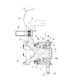
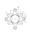
図1は、本発明に係る車輪用軸受装置の第1の実施形態を示す縦断面図、図2は、図1の側面図である。なお、以下の説明では、車両に組み付けた状態で車両の外側寄りとなる側をアウトボード側(図面左側)、中央寄り側をインボード側(図面右側)という。
Hereinafter, embodiments of the present invention will be described in detail with reference to the drawings.
FIG. 1 is a longitudinal sectional view showing a first embodiment of a wheel bearing device according to the present invention, and FIG. 2 is a side view of FIG. In the following description, the side closer to the outer side of the vehicle when assembled to the vehicle is referred to as the outboard side (left side in the drawing), and the side closer to the center is referred to as the inboard side (right side in the drawing).
この車輪用軸受装置は、従動輪を回転自在に支承する車輪用軸受装置であって、車輪用軸受装置2は、内方部材3と外方部材4、および両部材3、4間に転動自在に収容された複列の転動体(ボール)5、5とを備えている。ここで、内方部材3は、ハブ輪1と、このハブ輪1に圧入された内輪10とを指す。
This wheel bearing device is a wheel bearing device that rotatably supports a driven wheel. The
ハブ輪1は、外周のアウトボード側の端部に放射状に延びる4つに分割された車輪取付フランジ6(以下、車輪取付アームと言う)を一体に有し、この車輪取付アーム6の円周等配位置には車輪を締結するためのハブボルト6aが植設されている。車輪取付アーム6は、ハブボルト挿通孔6bの近傍を除く部分を切欠いて、各ハブボルト挿通孔6bの形成部分と略同じ幅でもって、環状の基部、すなわち、後述するブレーキパイロット部15から放射状に突出するように形成されている。さらに、車輪取付アーム6のインボード側の側面には、その基部に向って漸次肉厚になるようにリブ6cが形成されている。これにより、ハブ輪1の剛性を損なうことなく軽量化を達成することができる。
The
なお、本実施形態では、ハブボルト挿通孔6bの近傍を除く部分を切欠いて、各ハブボルト挿通孔6bの形成部分と略同じ幅でもって、環状の基部から放射状に突出するように形成された車輪取付アーム6を例示したが、これに限らず、従来のように、ハブボルト挿通孔の周辺を避けてハブボルト挿通孔間に、このハブボルト挿通孔のピッチ円直径より内径側まで深く切欠きが形成された車輪取付フランジのようなものであっても良い。
In the present embodiment, the wheel mounting formed by notching the portion except the vicinity of the hub
また、ハブ輪1の車輪取付アーム6のインボード側の外周には内側転走面1aと、この内側転走面1aから軸方向に延びる円筒状の小径段部7が形成され、この小径段部7に内輪10が所定のシメシロを介して圧入されている。そして、小径段部7の端部を径方向外方に塑性変形させて加締部8が形成されている。内輪10はこの加締部8によってハブ輪1に対して軸方向に固定され、所謂第3世代のセルフリテイン構造をなしている。したがって、ハブ輪1の剛性を増大させ、軽量・コンパクト化を図ることができる。また、従来のように内輪をナット等で強固に緊締して予圧量を管理する必要がないため、車両への組込性を簡便にすることができ、長期間その予圧量を維持することができると共に、部品点数を大幅に削減でき、組込性の向上と相俟って低コスト化と軽量・コンパクト化を達成することができる。なお、本発明に係る車輪用軸受においては、前記第3世代構造に限らず、例えば、ハブ輪の小径段部に一対の内輪が圧入される、所謂第2世代構造であっても良い。
Further, an inner rolling surface 1a and a cylindrical small
外方部材4の内周には複列の外側転走面4a、4aが形成され、これら外側転走面4a、4aに対向する内方部材3の内側転走面のうち、前記一方の内側転走面1aはハブ輪1に、そして、他方の内側転走面10aは内輪10の外周にそれぞれ形成されている。これら両転走面4a、1aおよび4a、10a間に複列の転動体5、5が収容され、これら複列の転動体5、5は転動自在に保持器9に保持されている。
Double rows of outer rolling surfaces 4a and 4a are formed on the inner periphery of the
外方部材4のアウトボード側の端部にはシール11が装着され、外方部材4と内方部材3との環状空間を密封している。一方、外方部材4のインボード側の端部には、カップ状のシールキャップ(図示せず)が装着され、外方部材4の開口部を閉塞している。これらシール11およびシールキャップにより、軸受内部に封入された潤滑グリースの外部への漏洩と、外部から雨水やダスト等が軸受内部に侵入するのを防止している。
A
また、外方部材4は、外周に懸架装置を構成するナックル(図示せず)に取り付けられる車体取付フランジ4bを一体に有し、この車体取付フランジ4bの外周部に複数のボルト挿通孔13が穿設されている。この車体取付フランジ4bは、その外周部のうちボルト挿通孔13の近傍を除く部分を切欠いて、各ボルト挿通孔13の形成部分だけが外径側に放射状に突出する形状に形成されている。すなわち、車体取付フランジ4bは、円周方向に離れた複数の部分フランジ14に分割されている。そして、ボルト挿通孔13に貫通するナックルボルト(図示せず)によりナックルに固定される。さらに、外方部材4のインボード側の端部には、前記車体取付フランジ4bから軸方向に延びる円筒状のナックルパイロット部4cが形成され、このナックルパイロット部4cの外径面にナックルが嵌合される。
Further, the
このように、外方部材4は、外周に車体取付フランジ4bを有し、この車体取付フランジ4bから放射状に延びる複数の部分フランジ14が形成されているので、外方部材4の剛性を損なうことなく軽量化を達成することができる。なお、前記ナックルパイロット部4cが、その円周方向の複数箇所に切欠きが設けられ、断続して突片状に形成されていても良い。これにより、外方部材4の剛性を低下させることなく軽量化を図ることができる。
Thus, the
また、本実施形態では、車輪取付アーム6が、ハブボルト挿通孔6bの近傍を除く部分を切欠いて、各ハブボルト挿通孔6bの形成部分だけが環状の基部から外径側に略同じ幅でもって突出するように形成されているので、外方部材4をナックルに締結する際に、この車輪取付アーム6に邪魔されることなく、工具にて容易にナックルボルトを締結することができ、組立作業を簡便化することができる。
Further, in the present embodiment, the
ハブ輪1は、S53C等の炭素0.40〜0.80wt%を含む中炭素鋼で形成され、車輪取付アーム6のインボード側の基部および小径段部7に亙り高周波焼入れによって表面硬さを54〜64HRCの範囲に硬化処理されている。なお、加締部8は、鍛造後の素材表面硬さ24HRC以下の未焼入れ部としている。これにより、ハブ輪1の剛性が向上すると共に、内輪10との嵌合面のフレッティング摩耗を防止することができ、ハブ輪1の耐久性が向上する。また、加締部8を塑性変形させる時の加工性が向上すると共に、加工時におけるクラック等の発生を防止してその品質の信頼性が向上する。
The
また、外方部材4は、ハブ輪1と同様、S53C等の炭素0.40〜0.80wt%を含む中炭素鋼で形成され、複列の外側転走面4a、4aに高周波焼入れによって表面硬さを54〜64HRCの範囲に硬化処理されている。一方、内輪10は、SUJ2等の高炭素クロム軸受鋼からなり、ズブ焼入れにより芯部まで54〜64HRCの範囲で硬化処理されている。なお、ここでは、転動体5、5をボールとした複列アンギュラ玉軸受を例示したが、これに限らず転動体に円錐ころを使用した複列円錐ころ軸受であっても良い。
Similarly to the
本実施形態では、図1に示すように、ハブ輪1の車輪取付アーム6の基部にはアウトボード側に延びる円筒状のブレーキパイロット部15が形成され、ブレーキロータ16の内径面を案内している。また、このブレーキパイロット部15からさらにアウトボード側に延びてホイールパイロット部17が形成されている。このホイールパイロット部17は、ブレーキロータに重ねて装着されるホイール18の内径面を案内するもので、前記ブレーキパイロット部15よりも僅かに小径に形成されている。そして、その円周方向の複数箇所に切欠きが設けられ、断続して突片状に形成されている。ここでは、この断続したホイールパイロット部17は、隣り合う車輪取付アーム6間に、円周等配位置に形成されている。これにより、ハブ輪1の剛性を低下させることなく軽量化を図ることができる。
In this embodiment, as shown in FIG. 1, a cylindrical
なお、本実施形態では、断続したホイールパイロット部17が、隣り合う車輪取付アーム6間の等配位置に形成されている。このように形成されれば、車輪取付アーム6における環状の基部が周方向に亙って比較的に均一な肉厚となり、ハブ輪1の鍛造工程において、鍛造素材の塑性流動が容易となって鍛造加工性が向上する。これにより、鍛造精度が向上すると共に、生産性が上がり低コスト化を達成することができる。さらに、車輪取付アーム6のインボード側の基部に高周波焼入れによる熱処理変形がこのホイールパイロット部17に及び難く、寸法精度が安定して従来の機能を損なうことなく、ホイール18の取付精度を確保することができる。なお、前述したブレーキロータ18は、ドラムブレーキにおけるブレーキドラムからなるが、ブレーキロータ18は、この他にディスクブレーキにおけるブレーキディスクであっても良い。
In the present embodiment, the intermittent
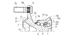
図3は、本発明に係る車輪用軸受装置の第2の実施形態を示す縦断面図、図4は、図3の側面図である。なお、本実施形態は、前述した実施形態と外方部材の構成のみが異なるだけで、ハブ輪1の断続したホイールパイロット部17が隣り合う車輪取付アーム6間に等配位置に形成されている。その他同一の部品や部位には同じ符号を付してその重複した説明を省略する。
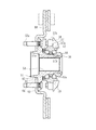
FIG. 3 is a longitudinal sectional view showing a second embodiment of the wheel bearing device according to the present invention, and FIG. 4 is a side view of FIG. In this embodiment, only the configuration of the outer member is different from that of the above-described embodiment, and the
外方部材19は、外周に突出した環状の車体取付部19bを一体に有し、この車体取付部19bから放射状に延びる4本の車体取付アーム20が形成され、これら車体取付アーム20の端部にそれぞれボルト挿通孔21が穿設されている。この車体取付アーム20は、ボルト挿通孔21の近傍を除く部分を切欠いて、各ボルト挿通孔21の形成部分と略同じ幅でもって、車体取付部19bから放射状に突出するように形成されている。そして、ボルト挿通孔21に貫通するナックルボルト(図示せず)により、懸架装置を構成するナックル(図示せず)に固定される。さらに、外方部材19のインボード側の端部には、前記車体取付部19bから軸方向に延びる円筒状のナックルパイロット部19cが形成され、このナックルパイロット部19cの外径面にナックルが嵌合される。
The
このように、外方部材19は、外周に突出した環状の車体取付部19bを有し、この車体取付部19bから放射状に延びる車体取付アーム20が略同じ幅でもって形成されているので、外方部材19の剛性を損なうことなく軽量化を達成することができ、ハブ輪1の軽量化と相俟って装置の可及的な軽量化を達成することができる。なお、前記ナックルパイロット部19cが、その円周方向の複数箇所に切欠きが設けられ、断続して突片状に形成されていても良い。これにより、外方部材19の剛性を低下させることなく一層軽量化を図ることができる。
Thus, the
以上、本発明の実施の形態について説明を行ったが、本発明はこうした実施の形態に何等限定されるものではなく、あくまで例示であって、本発明の要旨を逸脱しない範囲内において、さらに種々なる形態で実施し得ることは勿論のことであり、本発明の範囲は、特許請求の範囲の記載によって示され、さらに特許請求の範囲に記載の均等の意味、および範囲内のすべての変更を含む。 The embodiment of the present invention has been described above, but the present invention is not limited to such an embodiment, and is merely an example, and various modifications can be made without departing from the scope of the present invention. Of course, the scope of the present invention is indicated by the description of the scope of claims, and further, the equivalent meanings described in the scope of claims and all modifications within the scope of the scope of the present invention are included. Including.
本発明に係る車輪用軸受装置は、駆動輪用、従動輪用、あるいは転動体がボール、円錐ころ等、あらゆる構造の内輪回転タイプの車輪用軸受装置に適用することができる。 The wheel bearing device according to the present invention can be applied to an inner ring rotating type wheel bearing device of any structure such as a driving wheel, a driven wheel, or a rolling element having a ball, a tapered roller or the like.
1・・・・・・・・・・・・・・・・・ハブ輪
1a、10a・・・・・・・・・・・・内側転走面
2・・・・・・・・・・・・・・・・・車輪用軸受装置
3・・・・・・・・・・・・・・・・・内方部材
4、19・・・・・・・・・・・・・・外方部材
4a・・・・・・・・・・・・・・・・外側転走面
4b・・・・・・・・・・・・・・・・車体取付フランジ
4c・・・・・・・・・・・・・・・・ナックルパイロット部
5・・・・・・・・・・・・・・・・・転動体
6・・・・・・・・・・・・・・・・・車輪取付アーム
6a・・・・・・・・・・・・・・・・ハブボルト
6b・・・・・・・・・・・・・・・・ハブボルト挿通孔
6c・・・・・・・・・・・・・・・・リブ
7・・・・・・・・・・・・・・・・・小径段部
8・・・・・・・・・・・・・・・・・加締部
9・・・・・・・・・・・・・・・・・保持器
10・・・・・・・・・・・・・・・・内輪
11・・・・・・・・・・・・・・・・シール
12・・・・・・・・・・・・・・・・車体取付アーム
13・・・・・・・・・・・・・・・・ボルト挿通孔
14・・・・・・・・・・・・・・・・部分フランジ
15・・・・・・・・・・・・・・・・ブレーキパイロット部
16・・・・・・・・・・・・・・・・ブレーキロータ
17・・・・・・・・・・・・・・・・ホイールパイロット部
18・・・・・・・・・・・・・・・・ホイール
19b・・・・・・・・・・・・・・・車体取付部
19c・・・・・・・・・・・・・・・ナックルパイロット部
20・・・・・・・・・・・・・・・・車体取付アーム
21・・・・・・・・・・・・・・・・ボルト挿通孔
51・・・・・・・・・・・・・・・・ハブ輪
51a、55a・・・・・・・・・・・内側転走面
51b・・・・・・・・・・・・・・・小径段部
52・・・・・・・・・・・・・・・・車輪用軸受装置
53・・・・・・・・・・・・・・・・車輪取付フランジ
53a・・・・・・・・・・・・・・・ハブボルト
54・・・・・・・・・・・・・・・・スプライン
55・・・・・・・・・・・・・・・・内輪
56・・・・・・・・・・・・・・・・加締部
57・・・・・・・・・・・・・・・・外方部材
57a・・・・・・・・・・・・・・・外側転走面
57b・・・・・・・・・・・・・・・車体取付部
58・・・・・・・・・・・・・・・・ナックル
59・・・・・・・・・・・・・・・・転動体
60・・・・・・・・・・・・・・・・ブレーキロータ
61・・・・・・・・・・・・・・・・ボルト挿通孔
62・・・・・・・・・・・・・・・・切欠き部
63・・・・・・・・・・・・・・・・薄肉部
64・・・・・・・・・・・・・・・・厚肉部
65・・・・・・・・・・・・・・・・パイロット部
66・・・・・・・・・・・・・・・・側面
67・・・・・・・・・・・・・・・・隅部
1 ・ ・ ・ ・ ・ ・ ・ ・ ・ ・ ・
Claims (4)
アウトボード側の端部に車輪取付フランジを一体に有し、外周に軸方向に延びる円筒状の小径段部が形成されたハブ輪、およびこのハブ輪の小径段部に圧入された少なくとも一つの内輪とからなり、外周に前記複列の外側転走面に対向する複列の内側転走面が形成された内方部材と、
前記両転走面間に転動自在に収容された複列の転動体と、を備えた車輪用軸受装置において、
前記車輪取付フランジの円周等配に穿設されたハブボルト挿通孔の周辺を避けて該ハブボルト挿通孔間に、このハブボルト挿通孔のピッチ円直径より内径側まで切欠きが形成されると共に、
前記ハブ輪が、前記車輪取付フランジよりもアウトボード側に延びてブレーキロータの内径面を案内するブレーキパイロット部、およびこのブレーキパイロット部からさらにアウトボード側に延びてホイールの内径面を案内するホイールパイロット部を有し、少なくともこのホイールパイロット部が円周方向に離れた複数の部分ホイールパイロット部に分割して形成され、当該ホイールパイロット部が前記車輪取付フランジの切欠きの位置に配設されていることを特徴とする車輪用軸受装置。 An outer member having a double row outer raceway formed on the inner periphery;
A hub wheel integrally having a wheel mounting flange at the end on the outboard side and having a cylindrical small-diameter step portion extending in the axial direction on the outer periphery, and at least one press-fitted into the small-diameter step portion of the hub wheel An inner member formed of an inner ring, and an inner member formed with a double row inner raceway facing the outer raceway of the double row on the outer periphery;
In a wheel bearing device comprising: a double-row rolling element accommodated between the rolling surfaces so as to be freely rollable;
A notch is formed between the hub bolt insertion holes, avoiding the periphery of the hub bolt insertion holes drilled at equal circumferences of the wheel mounting flanges, from the pitch circle diameter of the hub bolt insertion holes to the inner diameter side,
The hub wheel extends to the outboard side from the wheel mounting flange to guide the inner diameter surface of the brake rotor, and the wheel further extends from the brake pilot portion to the outboard side to guide the inner diameter surface of the wheel. A pilot portion, and at least the wheel pilot portion is formed by being divided into a plurality of partial wheel pilot portions separated in the circumferential direction, and the wheel pilot portion is disposed at a notch position of the wheel mounting flange. A wheel bearing device characterized by comprising:
Priority Applications (1)
| Application Number | Priority Date | Filing Date | Title |
|---|---|---|---|
| JP2004121016A JP2005297925A (en) | 2004-04-16 | 2004-04-16 | Bearing device for wheel |
Applications Claiming Priority (1)
| Application Number | Priority Date | Filing Date | Title |
|---|---|---|---|
| JP2004121016A JP2005297925A (en) | 2004-04-16 | 2004-04-16 | Bearing device for wheel |
Publications (1)
| Publication Number | Publication Date |
|---|---|
| JP2005297925A true JP2005297925A (en) | 2005-10-27 |
Family
ID=35329974
Family Applications (1)
| Application Number | Title | Priority Date | Filing Date |
|---|---|---|---|
| JP2004121016A Pending JP2005297925A (en) | 2004-04-16 | 2004-04-16 | Bearing device for wheel |
Country Status (1)
| Country | Link |
|---|---|
| JP (1) | JP2005297925A (en) |
Cited By (7)
| Publication number | Priority date | Publication date | Assignee | Title |
|---|---|---|---|---|
| JP2007186029A (en) * | 2006-01-12 | 2007-07-26 | Jtekt Corp | Rolling bearing device for wheels |
| JP2008030554A (en) * | 2006-07-27 | 2008-02-14 | Ntn Corp | Bearing device for wheel |
| JP2008030645A (en) * | 2006-07-31 | 2008-02-14 | Ntn Corp | Wheel bearing device |
| WO2009001548A1 (en) * | 2007-06-28 | 2008-12-31 | Ntn Corporation | Wheel bearing device |
| WO2009060605A1 (en) * | 2007-11-06 | 2009-05-14 | Ntn Corporation | Bearing device for wheel |
| JP2017081407A (en) * | 2015-10-28 | 2017-05-18 | 日本精工株式会社 | Hub unit bearing |
| JP2019089380A (en) * | 2017-11-13 | 2019-06-13 | 日本精工株式会社 | Hub unit bearing and hub unit bearing with braking rotor |
-
2004
- 2004-04-16 JP JP2004121016A patent/JP2005297925A/en active Pending
Cited By (15)
| Publication number | Priority date | Publication date | Assignee | Title |
|---|---|---|---|---|
| JP2007186029A (en) * | 2006-01-12 | 2007-07-26 | Jtekt Corp | Rolling bearing device for wheels |
| JP2008030554A (en) * | 2006-07-27 | 2008-02-14 | Ntn Corp | Bearing device for wheel |
| JP2008030645A (en) * | 2006-07-31 | 2008-02-14 | Ntn Corp | Wheel bearing device |
| CN101743133B (en) * | 2007-06-28 | 2012-06-06 | Ntn株式会社 | Wheel bearing apparatus for a vehicle |
| JP2009008165A (en) * | 2007-06-28 | 2009-01-15 | Ntn Corp | Wheel bearing device |
| DE112008001720T5 (en) | 2007-06-28 | 2010-06-17 | NTN Corporation, Osaka-shi | Wheel bearing device for a vehicle |
| US7942585B2 (en) | 2007-06-28 | 2011-05-17 | Ntn Corporation | Wheel bearing apparatus for a vehicle |
| WO2009001548A1 (en) * | 2007-06-28 | 2008-12-31 | Ntn Corporation | Wheel bearing device |
| DE112008001720B4 (en) | 2007-06-28 | 2021-11-25 | Ntn Corporation | Wheel bearing device for a vehicle |
| WO2009060605A1 (en) * | 2007-11-06 | 2009-05-14 | Ntn Corporation | Bearing device for wheel |
| JP2009113635A (en) * | 2007-11-06 | 2009-05-28 | Ntn Corp | Wheel bearing device |
| US8568036B2 (en) | 2007-11-06 | 2013-10-29 | Ntn Corporation | Wheel bearing apparatus for a vehicle |
| JP2017081407A (en) * | 2015-10-28 | 2017-05-18 | 日本精工株式会社 | Hub unit bearing |
| JP2019089380A (en) * | 2017-11-13 | 2019-06-13 | 日本精工株式会社 | Hub unit bearing and hub unit bearing with braking rotor |
| JP7098913B2 (en) | 2017-11-13 | 2022-07-12 | 日本精工株式会社 | Hub unit bearing and hub unit bearing with rotating body for braking |
Similar Documents
| Publication | Publication Date | Title |
|---|---|---|
| JP5134340B2 (en) | Wheel bearing device | |
| JP5031460B2 (en) | Wheel bearing device | |
| JP2007126087A (en) | Bearing device for wheel | |
| JP2008100632A (en) | Bearing device for wheel | |
| JP4936712B2 (en) | Wheel bearing device | |
| JP2005297925A (en) | Bearing device for wheel | |
| JP2008055984A (en) | Bearing device for wheel | |
| JP2010089664A (en) | Bearing device for wheel | |
| JP2008284960A (en) | Wheel bearing system | |
| JP2011051474A (en) | Bearing device for wheel | |
| JP2006137297A (en) | Bearing device for wheel | |
| JP5187877B2 (en) | Wheel bearing device | |
| JP4844967B2 (en) | Wheel bearing device | |
| JP2005289147A (en) | Bearing device for wheel | |
| JP2006007791A (en) | Bearing unit for wheel | |
| JP2005289319A (en) | Bearing device for wheel | |
| JP5024850B2 (en) | Wheel bearing device | |
| JP5236097B2 (en) | Wheel bearing device | |
| JP4994717B2 (en) | Wheel bearing device | |
| JP2006341751A (en) | Bearing device for vehicle wheel | |
| JP2008121838A (en) | Wheel bearing device | |
| JP2006007910A (en) | Bearing device for wheel | |
| JP5000206B2 (en) | Wheel bearing device | |
| JP4986277B2 (en) | Wheel bearing device | |
| JP4986115B2 (en) | Wheel bearing device |