JP2007117908A - Septic tank - Google Patents
Septic tank Download PDFInfo
- Publication number
- JP2007117908A JP2007117908A JP2005314524A JP2005314524A JP2007117908A JP 2007117908 A JP2007117908 A JP 2007117908A JP 2005314524 A JP2005314524 A JP 2005314524A JP 2005314524 A JP2005314524 A JP 2005314524A JP 2007117908 A JP2007117908 A JP 2007117908A
- Authority
- JP
- Japan
- Prior art keywords
- tank
- treated
- water
- solid
- liquid separation
- Prior art date
- Legal status (The legal status is an assumption and is not a legal conclusion. Google has not performed a legal analysis and makes no representation as to the accuracy of the status listed.)
- Pending
Links
Images


Abstract
Description
本発明は、被処理水が外部から流入する嫌気槽と、前記嫌気槽で嫌気処理された被処理水を好気処理する好気槽と、前記好気槽で好気処理された被処理水中の固形分を沈殿させる沈殿槽とを備え、前記沈殿槽の被処理水を外部に排出可能に構成してある浄化槽に関する。 The present invention includes an anaerobic tank into which treated water flows from the outside, an aerobic tank for aerobically treating the treated water that has been anaerobically treated in the anaerobic tank, and the treated water that has been aerobically treated in the aerobic tank. The present invention relates to a septic tank comprising a settling tank for precipitating the solid content of the settling tank and configured to discharge water to be treated in the settling tank to the outside.
上記浄化槽では、従来、嫌気槽を、被処理水が外部から流入する夾雑物除去槽と、嫌気濾床槽とに仕切り壁で仕切り、夾雑物除去槽と嫌気濾床槽とを連通する流入口を、通常運転状態における液面の昇降高さ位置に合わせた上下幅で、その仕切り壁に設けて、通常運転状態において、夾雑物除去槽への被処理水の流入量に応じて、夾雑物除去槽の液面と嫌気濾床槽の液面とが、流入口を通して連続している状態で、同じレベルで昇降するように構成し、嫌気濾床槽の被処理水をポンプで好気槽に移送するように構成してある。
また、好気槽で好気処理された被処理水を、好気槽と沈殿槽とを区画している吊り壁の下端と槽底との間の流入口から沈殿槽の下部に流入させて、沈殿槽の被処理水を外部に排出可能に構成してある(例えば、特許文献1参照)。
In the septic tank, conventionally, an anaerobic tank is divided into a contaminant removal tank into which treated water flows from the outside and an anaerobic filter bed tank with a partition wall, and the inlet for communicating the contaminant removal tank and the anaerobic filter bed tank Is provided on the partition wall in a vertical width that matches the elevation level position of the liquid level in the normal operation state, and in the normal operation state, depending on the inflow amount of the treated water into the contaminant removal tank, The liquid level in the removal tank and the liquid level in the anaerobic filter bed tank are configured to rise and fall at the same level while being continuous through the inlet, and the water to be treated in the anaerobic filter bed tank is pumped to the aerobic tank. It is comprised so that it may be transferred to.
In addition, the water to be treated aerobically treated in the aerobic tank is allowed to flow into the lower part of the settling tank from the inlet between the lower end of the suspension wall and the bottom of the tank that separates the aerobic tank and the settling tank. The water to be treated in the settling tank is configured to be discharged to the outside (see, for example, Patent Document 1).
従来の浄化槽は、上記のように、通常運転状態において、夾雑物除去槽への被処理水の流入量に応じて、夾雑物除去槽の液面と嫌気濾床槽の液面とが、流入口を通して連続している状態で、同じレベルで昇降するように構成し、嫌気濾床槽の被処理水をポンプで好気槽に移送するように構成してあるので、夾雑物除去槽と嫌気濾床槽との全体が、実質的に流量調整槽として機能しており、夾雑物除去槽の被処理水に浮遊しているスカムが流入口を通して嫌気濾床槽に流入して、被処理水とともに好気槽に移送され易い欠点がある。
また、ディスポーザから流入する被処理水のように、固形分が比較的多くて処理負荷が高い被処理水が夾雑物除去槽に大量に流入すると、その固形分の多い被処理水が流入口を通して嫌気濾床槽に流入してポンプで好気槽に移送され、その好気槽から沈殿槽に槽底部から流入し、それらの固形分が、沈殿槽における被処理水の槽底部から上部へ向かう上昇流に乗って、充分に沈殿させることができないまま、被処理水と共に外部に排出され易い欠点がある。
本発明は上記実情に鑑みてなされたものであって、嫌気槽のスカムが好気槽に移送されにくく、ディスポーザから流入するような処理負荷が高い被処理水でも適切に浄化処理し易い浄化槽を提供することを目的とする。
In the conventional septic tank, as described above, in the normal operation state, the liquid level of the contaminant removal tank and the liquid level of the anaerobic filter bed tank flow according to the inflow amount of the treated water into the contaminant removal tank. It is configured to move up and down at the same level in a continuous state through the inlet, and it is configured to transfer the water to be treated in the anaerobic filter bed tank to the aerobic tank with a pump. The entire filter bed tank functions substantially as a flow rate adjustment tank, and the scum floating in the treated water in the contaminant removal tank flows into the anaerobic filter bed tank through the inlet, In addition, there is a drawback that it is easily transferred to the aerobic tank.
In addition, when a large amount of treated water having a relatively high solid content and a high processing load flows into the contaminant removal tank, such as treated water flowing from the disposer, the treated water having a large solid content passes through the inlet. It flows into the anaerobic filter bed tank and is transferred to the aerobic tank by a pump. From the aerobic tank, it flows into the sedimentation tank from the bottom of the tank, and the solids flow from the bottom of the treated water in the sedimentation tank to the top. There is a drawback that it is easy to be discharged to the outside together with the water to be treated without being sufficiently settled on the rising flow.
The present invention has been made in view of the above circumstances, and is a septic tank in which the scum of an anaerobic tank is difficult to be transferred to an aerobic tank, and it is easy to appropriately purify even water to be treated having a high processing load flowing from a disposer The purpose is to provide.
本発明の第1特徴構成は、被処理水が外部から流入する嫌気槽と、前記嫌気槽で嫌気処理された被処理水を好気処理する好気槽と、前記好気槽で好気処理された被処理水中の固形分を沈殿させる沈殿槽とを備え、前記沈殿槽の被処理水を外部に排出可能に構成してある浄化槽であって、前記嫌気槽を、被処理水が外部から流入する固液分離槽と、通常運転状態において、前記固液分離槽で固液分離された被処理水がオーバーフローで移流する流量調整槽とで構成し、前記流量調整槽の被処理水を前記好気槽に移送するポンプと、前記好気槽の被処理水を前記沈殿槽にオーバーフローで移流させる移流口と、前記沈殿槽で沈殿させた固形分を前記嫌気槽に返送する返送手段とを設け、前記沈殿槽の底面形状を、沈殿槽内部の水平方向に沿う横断面積が下部ほど小さくなる下窄まり形状に形成してある点にある。 The first characteristic configuration of the present invention includes an anaerobic tank into which treated water flows from the outside, an aerobic tank for aerobically treating the treated water that has been anaerobically treated in the anaerobic tank, and an aerobic treatment in the aerobic tank. And a sedimentation tank for precipitating solids in the treated water, wherein the treated water in the settling tank is configured to be discharged to the outside, wherein the anaerobic tank is treated from outside. An inflow solid-liquid separation tank, and a flow rate adjustment tank in which the water to be treated solid-liquid separated in the solid-liquid separation tank is transferred in an overflow state in a normal operation state, and the water to be treated in the flow rate adjustment tank is A pump for transferring to the aerobic tank; a transfer port for transferring the water to be treated in the aerobic tank to the settling tank by overflow; and a return means for returning the solid content precipitated in the settling tank to the anaerobic tank. Set the bottom shape of the settling tank along the horizontal direction inside the settling tank Lies in the product is is formed on the lower Subomari shape becomes smaller as the bottom.
〔作用及び効果〕
嫌気槽を、被処理水が外部から流入する固液分離槽と、通常運転状態において、固液分離槽で固液分離された被処理水がオーバーフローで移流する流量調整槽とで構成してあるので、固液分離槽の被処理水が流量調整槽にオーバーフローで穏やかに流入し、固液分離槽の被処理水に浮遊しているスカムが流量調整槽に流入しにくいとともに、ディスポーザから流入する被処理水のような、固形分が比較的多くて処理負荷が高い被処理水が固液分離槽に流入しても、充分時間を掛けて固液分離させ易く、固形分も流量調整槽に流入しにくい。
また、流量調整槽の被処理水を好気槽に移送するポンプを設けてあるので、スカムや固形分の流入が少ない被処理水を好気槽に移送して好気処理できるとともに、好気槽の被処理水を沈殿槽にオーバーフローで移流させる移流口を設けてあるので、好気槽で好気処理した被処理水中の固形分を、沈殿槽における被処理水の移流口から槽底部に向かう下降流に乗せて、効率良く沈殿させ易く、その沈殿槽で沈殿させた固形分を嫌気槽に返送する返送手段を設けてあるので、その固形分を嫌気槽で再度嫌気処理することができる。
その上、沈殿槽の底面形状を、沈殿槽内部の水平方向に沿う横断面積が下部ほど小さくなる下窄まり形状に形成してあるので、沈殿した固形分を沈殿槽の底部に堆積させ易く、返送手段によって嫌気槽に効率良く返送できる。
従って、嫌気槽のスカムが好気槽に移送されにくいとともに、固形分が比較的多くて処理負荷が高い被処理水が固液分離槽に短時間の間に大量に流入した結果、それらの固形分が、万一、流量調整槽と好気槽とを経て、沈殿槽に流入しても、それらの固形分を沈殿槽の底部に効率良く堆積させて嫌気槽に返送し易く、処理負荷が高い被処理水でも、固形分が外部に排出されないように適切に浄化処理し易い。
[Action and effect]
The anaerobic tank is composed of a solid-liquid separation tank into which treated water flows from the outside, and a flow rate adjusting tank in which the treated water separated in the solid-liquid separation tank in an ordinary operation state is transferred by overflow. Therefore, the water to be treated in the solid / liquid separation tank gently flows into the flow adjustment tank by overflow, and the scum floating in the water to be treated in the solid / liquid separation tank is difficult to flow into the flow adjustment tank and flows from the disposer. Even if water to be treated, such as water to be treated, having a relatively high solid content and a high processing load flows into the solid-liquid separation tank, it is easy to separate the solid and liquid over a sufficient amount of time. Difficult to flow in.
In addition, since a pump for transferring the water to be treated in the flow rate adjustment tank to the aerobic tank is provided, the water to be treated with little inflow of scum and solids can be transferred to the aerobic tank for aerobic treatment. Since the advection port for advancing the treated water in the tank to the settling tank by overflow is provided, the solid content in the treated water that has been aerobically treated in the aerobic tank is transferred from the treated water transfer port in the settling tank to the bottom of the tank. It is easy to precipitate efficiently by putting it on the downward flow, and since there is a return means for returning the solid content precipitated in the settling tank to the anaerobic tank, the solid content can be anaerobically treated again in the anaerobic tank. .
In addition, since the bottom shape of the precipitation tank is formed in a constricted shape in which the cross-sectional area along the horizontal direction inside the precipitation tank becomes smaller in the lower part, it is easy to deposit the precipitated solid content at the bottom of the precipitation tank, It can be returned efficiently to the anaerobic tank by the return means.
Therefore, the scum of the anaerobic tank is difficult to be transferred to the aerobic tank, and the treated water with a relatively high solid content and a high processing load flows into the solid-liquid separation tank in a short time. Even if the water flows into the sedimentation tank via the flow rate adjustment tank and the aerobic tank, it is easy to efficiently deposit these solids on the bottom of the precipitation tank and return them to the anaerobic tank. Even with high water to be treated, it is easy to purify appropriately so that the solid content is not discharged to the outside.
本発明の第2特徴構成は、前記固液分離槽内の被処理水の流動方向を下向きに規制する下向き規制流路と、前記固液分離槽内の被処理水の流動方向を上向きに規制する上向き規制流路とを、前記固液分離槽の径方向で互いに対向する槽壁部分に沿わせて各別に設けて、外部からの被処理水が前記下向き規制流路を通して前記固液分離槽に流入可能、かつ、前記固液分離槽の被処理水が前記上向き規制流路を通してオーバーフローで前記流量調整槽に移流可能に構成し、前記固形分を前記下向き規制流路から前記固液分離槽に返送可能に構成してある点にある。 The second characteristic configuration of the present invention includes a downward regulating channel for regulating the flow direction of the water to be treated in the solid-liquid separation tank downward, and the flow direction of the water to be treated in the solid-liquid separation tank regulated upward. And an upward restriction flow path separately provided along the tank wall portions facing each other in the radial direction of the solid-liquid separation tank, so that water to be treated from the outside passes through the downward restriction flow path and the solid-liquid separation tank The solid-liquid separation tank is configured so that the water to be treated in the solid-liquid separation tank can be transferred to the flow rate adjustment tank by overflow through the upward restriction flow path, and the solid content is transferred from the downward restriction flow path to the solid-liquid separation tank. It is in a point that it can be returned to.
〔作用及び効果〕
固液分離槽内の被処理水の流動方向を下向きに規制する下向き規制流路と、固液分離槽内の被処理水の流動方向を上向きに規制する上向き規制流路とを、固液分離槽の径方向で互いに対向する槽壁部分に沿わせて各別に設けて、外部からの被処理水が下向き規制流路を通して固液分離槽に流入可能、かつ、固液分離槽の被処理水が上向き規制流路を通してオーバーフローで流量調整槽に移流可能に構成してあるので、外部からの被処理水を、下向き規制流路の出口から上向き規制流路の入り口に移動するまでの間、流入済みの被処理水に強制的に混合させる状態で、固液分離槽内において長時間に亘って滞留させて、充分に固液分離させた被処理水を流量調整槽に移流させ易い。
また、沈殿槽で沈殿させた固形分を下向き規制流路から固液分離槽に返送可能に構成してあるので、それらの固形分を、固液分離槽内において長時間に亘って滞留させて、効率良く固液分離することができる。
[Action and effect]
Solid-liquid separation of a downward regulating channel that regulates the flow direction of the water to be treated in the solid-liquid separation tank and an upward regulating channel that regulates the flow direction of the water to be treated in the solid-liquid separation tank upward Provided separately along the tank walls facing each other in the radial direction of the tank, the water to be treated from the outside can flow into the solid-liquid separation tank through the downward regulating channel, and the water to be treated of the solid-liquid separation tank Is configured to be able to be transferred to the flow rate adjustment tank by overflow through the upward restriction flow path, so that the treated water from the outside flows in from the outlet of the downward restriction flow path to the entrance of the upward restriction flow path. The water to be treated which has been sufficiently solid-liquid separated by being retained in the solid-liquid separation tank for a long time in a state where it is forcibly mixed with the water to be treated is easily transferred to the flow rate adjusting tank.
In addition, since the solid content precipitated in the sedimentation tank can be returned from the downward regulating channel to the solid-liquid separation tank, the solid content is retained in the solid-liquid separation tank for a long time. Thus, solid-liquid separation can be performed efficiently.
以下に本発明の実施の形態を図面に基づいて説明する。
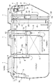
図1〜図4は、生活排水(汚水)を被処理水として浄化処理するための本発明による浄化槽を示し、図1,図2に示すように、マンホール1などを備えた槽本体2に、流入口としての流入管3を通して被処理水が外部から流入する嫌気槽Aと、嫌気槽Aで嫌気処理された被処理水を好気処理する好気槽Bと、好気槽Bで好気処理された被処理水中の固形分を沈殿させる沈殿槽Cと、沈殿槽Cを通過した被処理水を消毒処理する消毒槽Dとを区画形成し、沈殿槽Cで固形分を沈殿させた被処理水を、消毒槽Dを介して、放流口としての流出管4から外部に排出可能に構成してある。
Embodiments of the present invention will be described below with reference to the drawings.
1 to 4 show a septic tank according to the present invention for purifying domestic wastewater (sewage) as water to be treated, and as shown in FIGS. 1 and 2, a
前記嫌気槽Aは、その内側を第1仕切り壁5で仕切って、被処理水が流入管3を通して外部から流入する固液分離槽A1と、通常運転状態において、固液分離槽A1で固液分離された被処理水が第1仕切り壁5の上部に形成してある第1移流口6からオーバーフローで移流する流量調整槽A2とで構成してある。
The anaerobic tank A is partitioned by the
前記固液分離槽A1は、固液分離槽内に流入する被処理水の流動方向を下向きに規制する下向き規制流路7と、固液分離槽内から流出する被処理水の流動方向を上向きに規制する上向き規制流路8とを、固液分離槽A1の径方向で互いに対向する槽壁部分2a,5aに沿わせて各別に設けて、外部からの被処理水が流入管3から下向き規制流路7を通して固液分離槽A1に流入可能、かつ、固液分離槽A1の被処理水が上向き規制流路8を通して第1移流口6からオーバーフローで流量調整槽A2に移流可能に構成してある。
The solid-liquid separation tank A1 has a downward regulating
前記下向き規制流路7は、水平断面形状が略コの字状の第1バッフル9を、その上端部分で流入管3の出口側を取り囲む状態で、通常運転状態における流量調整槽A2の最高液面高さHWL よりも高い位置と、最低液面高さLWL と略同じ高さ位置とに亘って、槽本体2における槽壁部分2aの内側に設けて、その内側に形成してある。
The downward regulating
前記上向き規制流路8は、水平断面形状が略コの字状の第2バッフル10を、その上端部分で第1移流口6を取り囲む状態で、通常運転状態における流量調整槽A2の最高液面高さHWL よりも高い位置と、最低液面高さLWL よりも低い位置とに亘って、第1仕切り壁5における槽壁部分5aの固液分離槽側に設けて、その内側に形成してある。
The upward restricting flow path 8 includes a
前記流量調整槽A2は、図3にも示すように、被処理水中に含まれる溶解性有機物質を嫌気性濾床11の濾材に付着生息している嫌気性微生物によって分解処理する嫌気性濾床槽で構成してあり、流量調整槽A2の被処理水を略一定流量で、配管12を通して好気槽Bに移送する定容量式の第1エアリフトポンプ13と、嫌気性濾床11の逆洗管14とを設けてある。
As shown in FIG. 3, the flow rate adjusting tank A <b> 2 is an anaerobic filter bed that decomposes soluble organic substances contained in the water to be treated by anaerobic microorganisms attached to the filter medium of the
前記第1エアリフトポンプ13は、嫌気槽Aと好気槽Bとを仕切る第2仕切り壁15の嫌気槽側に、水平断面形状が略コの字状の第3バッフル16を、通常運転状態における流量調整槽A2の最高液面高さHWL よりも高い位置と、嫌気性濾床11の下面と略同じ高さ位置とに亘って設けて、その内側に設置してある。
The first
前記好気槽Bは、槽内に流動状態で充填してあるポリエチレン樹脂やポリプロピレン樹脂,ポリウレタン樹脂等の樹脂製の担体を、ばっ気用散気管17から吹き込んだ空気でばっ気攪拌することにより、担体の表面に付着生成している生物膜と被処理水とを繰り返し接触させて、被処理水中の有機物の分解除去や窒素化合物の酸化を行う担体反応槽で構成してあり、槽底部に溜まった汚泥を槽外に引き出し可能な汚泥引き出し管20を設けてある。
The aerobic tank B is obtained by aeration and stirring of a carrier made of resin such as polyethylene resin, polypropylene resin, and polyurethane resin filled in a fluidized state in the tank with air blown from the
前記沈殿槽Cは、図4にも示すように、担体流出防止用の多孔板21を設けてある第2移流口22を、好気槽Bと沈殿槽Cとを仕切る第3仕切り壁23の上部に形成して、好気槽Bの被処理水を第2移流口22からオーバーフローで移流させるように構成してあり、その底面24の形状を沈殿槽内部の水平方向に沿う横断面積が下部ほど小さくなる下窄まり形状に形成し、沈殿槽Cで沈殿させた固形分を嫌気槽Aに返送する返送手段25を設けてある。
As shown in FIG. 4, the settling tank C has a
そして、水平断面形状が略コの字状の第4バッフル26を、第2移流口22を取り囲む状態で、通常運転状態における流量調整槽A2の最高液面高さHWL よりも高い位置と、最低液面高さLWL よりも低い位置とに亘って、第3仕切り壁23の沈殿槽側に設けて、その内側を下向き流路27に形成し、第2移流口22から移流した被処理水が下向き流路27を通って槽底部に向かって下降流動するように構成してある。
Then, the
前記返送手段25は、第2エアリフトポンプ28を上下方向中間位置に備えた吸入管29を下向き流路27に挿通して、返送路18を形成している返送管19に連通接続するとともに、その吸入口30を槽底近くに開口させて、下窄まり形状の槽底に沈殿させた固形分を、第2エアリフトポンプ28の作動で、返送路18を通して、固液分離槽A1の下向き規制流路7から嫌気槽Aに返送できるように構成してある。
The return means 25 is connected to a
前記消毒槽Dは、沈殿槽Cと消毒槽Dとを仕切る第4仕切り壁31に第3移流口32を形成して、沈殿槽Cの被処理水を第3移流口32からオーバーフローで移流させるように構成してあり、薬剤筒33の塩素系消毒剤で被処理水を消毒した後、流出管4を通して外部に放流できるように構成してある。
The said disinfection tank D forms the
〔その他の実施形態〕
1.本発明による浄化槽は、好気槽の被処理水を、必要に応じて適宜の処理を行うための処理槽を経由して、沈殿槽にオーバーフローで移流させるように設けてあっても良い。
2.本発明による浄化槽は、沈殿槽の被処理水を、必要に応じて適宜の処理を行うための処理槽を経由して、消毒槽から外部に排出可能に構成してあっても良い。
[Other Embodiments]
1. The septic tank according to the present invention may be provided so that the water to be treated in the aerobic tank is transferred to the sedimentation tank by overflow through a treatment tank for performing an appropriate treatment as necessary.
2. The septic tank according to the present invention may be configured such that the water to be treated in the settling tank can be discharged from the disinfection tank to the outside via a treatment tank for performing an appropriate treatment as necessary.
2a 槽壁部分
5a 槽壁部分
7 下向き規制流路
8 上向き規制流路
13 ポンプ
22 移流口
25 返送手段
A 嫌気槽
A1 固液分離槽
A2 流量調整槽
B 好気槽
C 沈殿槽
2a
Claims (2)
前記沈殿槽の被処理水を外部に排出可能に構成してある浄化槽であって、
前記嫌気槽を、被処理水が外部から流入する固液分離槽と、通常運転状態において、前記固液分離槽で固液分離された被処理水がオーバーフローで移流する流量調整槽とで構成し、
前記流量調整槽の被処理水を前記好気槽に移送するポンプと、前記好気槽の被処理水を前記沈殿槽にオーバーフローで移流させる移流口と、前記沈殿槽で沈殿させた固形分を前記嫌気槽に返送する返送手段とを設け、
前記沈殿槽の底面形状を、沈殿槽内部の水平方向に沿う横断面積が下部ほど小さくなる下窄まり形状に形成してある浄化槽。 An anaerobic tank into which treated water flows from the outside, an aerobic tank for aerobically treating the treated water that has been anaerobically treated in the anaerobic tank, and a solid content in the treated water that has been aerobically treated in the aerobic tank A precipitation tank for precipitation,
A septic tank configured to discharge the treated water of the settling tank to the outside,
The anaerobic tank is composed of a solid-liquid separation tank into which treated water flows from the outside, and a flow rate adjusting tank in which the treated water separated in the solid-liquid separation tank in an ordinary operation state is transferred by overflow. ,
A pump for transferring the water to be treated in the flow rate adjusting tank to the aerobic tank, a transfer port for transferring the water to be treated in the aerobic tank to the settling tank by overflow, and a solid content precipitated in the settling tank. A return means for returning to the anaerobic tank;
The septic tank which formed the bottom face shape of the said sedimentation tank in the constriction shape where the cross-sectional area along the horizontal direction inside a sedimentation tank becomes small as the lower part.
前記固形分を前記下向き規制流路から前記固液分離槽に返送可能に構成してある請求項1記載の浄化槽。 A downward regulating channel for regulating the flow direction of the water to be treated in the solid-liquid separation tank downward, and an upward regulating channel for regulating the flow direction of the water to be treated in the solid-liquid separation tank upward, Provided separately along the tank wall portions facing each other in the radial direction of the solid-liquid separation tank, water to be treated from the outside can flow into the solid-liquid separation tank through the downward regulating channel, and the solid-liquid separation The water to be treated in the separation tank is configured to be able to be transferred to the flow rate adjusting tank by overflow through the upward regulating channel,
The septic tank of Claim 1 comprised so that the said solid content can be returned to the said solid-liquid separation tank from the said downward control flow path.
Priority Applications (1)
| Application Number | Priority Date | Filing Date | Title |
|---|---|---|---|
| JP2005314524A JP2007117908A (en) | 2005-10-28 | 2005-10-28 | Septic tank |
Applications Claiming Priority (1)
| Application Number | Priority Date | Filing Date | Title |
|---|---|---|---|
| JP2005314524A JP2007117908A (en) | 2005-10-28 | 2005-10-28 | Septic tank |
Publications (1)
| Publication Number | Publication Date |
|---|---|
| JP2007117908A true JP2007117908A (en) | 2007-05-17 |
Family
ID=38142327
Family Applications (1)
| Application Number | Title | Priority Date | Filing Date |
|---|---|---|---|
| JP2005314524A Pending JP2007117908A (en) | 2005-10-28 | 2005-10-28 | Septic tank |
Country Status (1)
| Country | Link |
|---|---|
| JP (1) | JP2007117908A (en) |
Cited By (6)
| Publication number | Priority date | Publication date | Assignee | Title |
|---|---|---|---|---|
| JP2007136378A (en) * | 2005-11-21 | 2007-06-07 | Hitachi Housetec Co Ltd | Septic tank |
| JP2009090216A (en) * | 2007-10-09 | 2009-04-30 | Kubota Corp | Aeration device for septic tank |
| JP2010284620A (en) * | 2009-06-15 | 2010-12-24 | Fuji Clean Co Ltd | Water treatment apparatus |
| JP2012143728A (en) * | 2011-01-14 | 2012-08-02 | Nishimatsu Constr Co Ltd | Filter unit |
| US10167216B2 (en) | 2012-09-14 | 2019-01-01 | Gregory D. Graves | High efficiency wastewater treatment system |
| US10676383B2 (en) | 2012-09-14 | 2020-06-09 | Gregory D. Graves | High efficiency wastewater treatment system |
Citations (12)
| Publication number | Priority date | Publication date | Assignee | Title |
|---|---|---|---|---|
| JPS53676U (en) * | 1976-06-22 | 1978-01-06 | ||
| JPS63185496A (en) * | 1987-01-26 | 1988-08-01 | Nagano Ekika:Kk | Compact joint septic tank |
| JPH01114096U (en) * | 1988-01-25 | 1989-08-01 | ||
| JPH02108798U (en) * | 1989-02-13 | 1990-08-29 | ||
| JPH0332997U (en) * | 1989-08-01 | 1991-03-29 | ||
| JPH05169075A (en) * | 1991-12-25 | 1993-07-09 | Nishihara Neo Kogyo Kk | Device and method for transferring liquid for clarification tank |
| JPH0824880A (en) * | 1994-07-20 | 1996-01-30 | Miyoshi Shokai:Kk | Combined treatment and purification tank |
| JPH0985269A (en) * | 1995-09-27 | 1997-03-31 | Sekisui Chem Co Ltd | Sewage treatment apparatus |
| JP2001062475A (en) * | 1999-08-30 | 2001-03-13 | Sanyo Electric Co Ltd | Water treating system |
| JP2003010871A (en) * | 2001-07-03 | 2003-01-14 | Kubota Corp | Sewage treatment apparatus and its operating method |
| JP2005185892A (en) * | 2003-12-24 | 2005-07-14 | Fuji Clean Kogyo Kk | Sewage treatment device |
| JP2005199175A (en) * | 2004-01-15 | 2005-07-28 | Daiei Sangyo Kk | Septic tank |
-
2005
- 2005-10-28 JP JP2005314524A patent/JP2007117908A/en active Pending
Patent Citations (12)
| Publication number | Priority date | Publication date | Assignee | Title |
|---|---|---|---|---|
| JPS53676U (en) * | 1976-06-22 | 1978-01-06 | ||
| JPS63185496A (en) * | 1987-01-26 | 1988-08-01 | Nagano Ekika:Kk | Compact joint septic tank |
| JPH01114096U (en) * | 1988-01-25 | 1989-08-01 | ||
| JPH02108798U (en) * | 1989-02-13 | 1990-08-29 | ||
| JPH0332997U (en) * | 1989-08-01 | 1991-03-29 | ||
| JPH05169075A (en) * | 1991-12-25 | 1993-07-09 | Nishihara Neo Kogyo Kk | Device and method for transferring liquid for clarification tank |
| JPH0824880A (en) * | 1994-07-20 | 1996-01-30 | Miyoshi Shokai:Kk | Combined treatment and purification tank |
| JPH0985269A (en) * | 1995-09-27 | 1997-03-31 | Sekisui Chem Co Ltd | Sewage treatment apparatus |
| JP2001062475A (en) * | 1999-08-30 | 2001-03-13 | Sanyo Electric Co Ltd | Water treating system |
| JP2003010871A (en) * | 2001-07-03 | 2003-01-14 | Kubota Corp | Sewage treatment apparatus and its operating method |
| JP2005185892A (en) * | 2003-12-24 | 2005-07-14 | Fuji Clean Kogyo Kk | Sewage treatment device |
| JP2005199175A (en) * | 2004-01-15 | 2005-07-28 | Daiei Sangyo Kk | Septic tank |
Cited By (6)
| Publication number | Priority date | Publication date | Assignee | Title |
|---|---|---|---|---|
| JP2007136378A (en) * | 2005-11-21 | 2007-06-07 | Hitachi Housetec Co Ltd | Septic tank |
| JP2009090216A (en) * | 2007-10-09 | 2009-04-30 | Kubota Corp | Aeration device for septic tank |
| JP2010284620A (en) * | 2009-06-15 | 2010-12-24 | Fuji Clean Co Ltd | Water treatment apparatus |
| JP2012143728A (en) * | 2011-01-14 | 2012-08-02 | Nishimatsu Constr Co Ltd | Filter unit |
| US10167216B2 (en) | 2012-09-14 | 2019-01-01 | Gregory D. Graves | High efficiency wastewater treatment system |
| US10676383B2 (en) | 2012-09-14 | 2020-06-09 | Gregory D. Graves | High efficiency wastewater treatment system |
Similar Documents
| Publication | Publication Date | Title |
|---|---|---|
| KR101686484B1 (en) | Method of sewage treatment | |
| JP2007117908A (en) | Septic tank | |
| JP4702748B2 (en) | Water treatment equipment | |
| JP2010247051A (en) | Water treatment apparatus | |
| JP4413077B2 (en) | Water treatment equipment | |
| JP2006289153A (en) | Method of cleaning sewage and apparatus thereof | |
| JP5814583B2 (en) | Septic tank | |
| JP2012213766A (en) | Sewage purification facility | |
| JP5771037B2 (en) | Sewage treatment equipment | |
| JP5259502B2 (en) | Water treatment equipment | |
| JP2002096090A (en) | Septic tank | |
| JP2006218435A (en) | Activated sludge treatment system | |
| JP5818360B2 (en) | Moving bed type filtration tank and septic tank equipped with moving bed type filtration tank | |
| KR100481821B1 (en) | Process and plant for wastewater treatment | |
| JP4022815B2 (en) | Solid-liquid separation tank and sewage septic tank having a filter medium layer in the second chamber | |
| JP2014069129A (en) | Water treatment device, moving-bed type filter tank, and clarification tank | |
| JP6004872B2 (en) | Moving bed filtration tank and septic tank | |
| JP4598705B2 (en) | Septic tank | |
| JP4999672B2 (en) | Wastewater septic tank | |
| KR960003926B1 (en) | Aerobic excrement tank | |
| JP4100873B2 (en) | Sewage treatment equipment | |
| WO2012133739A1 (en) | Sewerage clarification facility | |
| JP6632202B2 (en) | Septic tank | |
| KR100418429B1 (en) | A wastewater disposal plant using contact treatment method of variability facultative anaerobic | |
| JP4001514B2 (en) | Biological denitrification method and apparatus |
Legal Events
| Date | Code | Title | Description |
|---|---|---|---|
| A621 | Written request for application examination |
Free format text: JAPANESE INTERMEDIATE CODE: A621 Effective date: 20080919 |
|
| A977 | Report on retrieval |
Free format text: JAPANESE INTERMEDIATE CODE: A971007 Effective date: 20100526 |
|
| A131 | Notification of reasons for refusal |
Effective date: 20100603 Free format text: JAPANESE INTERMEDIATE CODE: A131 |
|
| A02 | Decision of refusal |
Effective date: 20101007 Free format text: JAPANESE INTERMEDIATE CODE: A02 |