JP2007103634A - Shape simulation method of semiconductor device - Google Patents
Shape simulation method of semiconductor device Download PDFInfo
- Publication number
- JP2007103634A JP2007103634A JP2005291004A JP2005291004A JP2007103634A JP 2007103634 A JP2007103634 A JP 2007103634A JP 2005291004 A JP2005291004 A JP 2005291004A JP 2005291004 A JP2005291004 A JP 2005291004A JP 2007103634 A JP2007103634 A JP 2007103634A
- Authority
- JP
- Japan
- Prior art keywords
- pattern
- semiconductor device
- shape
- simulation
- film
- Prior art date
- Legal status (The legal status is an assumption and is not a legal conclusion. Google has not performed a legal analysis and makes no representation as to the accuracy of the status listed.)
- Pending
Links
Images


Landscapes
- Mechanical Treatment Of Semiconductor (AREA)
- Finish Polishing, Edge Sharpening, And Grinding By Specific Grinding Devices (AREA)
Abstract
Description
本発明は、半導体デバイスの製造技術に関し、特に、半導体デバイスの表面をCMP(Chemical Mechanical Polishing)により研磨した後の表面形状を予測するシミュレーション方法に適用して有効な技術に関する。 The present invention relates to a semiconductor device manufacturing technique, and more particularly to a technique that is effective when applied to a simulation method for predicting a surface shape after the surface of a semiconductor device is polished by CMP (Chemical Mechanical Polishing).
従来、半導体デバイスの表面をCMPにより研磨した後の表面形状を予測するシミュレーション方法に関する技術としては、単位面積あたりのパターンが占める割合を増大もしくは減少させて、堆積する膜の種類を考慮する技術がある(例えば、非特許文献1)。
ところで、前記のような従来のシミュレーション方法に関する技術では、具体的な変更の手順については言及されておらず、また、同じデバイス上に存在する二種以上の高さを持つパターンの取り扱いを簡易に実施する手段についても言及されていない。 By the way, in the technology related to the conventional simulation method as described above, a specific change procedure is not mentioned, and handling of patterns having two or more heights existing on the same device is simplified. There is no mention of the means to implement.
そこで、本発明の目的は、パターン上への膜堆積・エッチングなどのプロセスによる形状変化や、デバイス上に混在する異なる段差のパターンを考慮した具体的なCMPシミュレーション方法を提供することにある。 SUMMARY OF THE INVENTION An object of the present invention is to provide a specific CMP simulation method that takes into account a shape change due to a process such as film deposition / etching on a pattern and a pattern of different steps mixed on a device.
本発明の前記ならびにその他の目的と新規な特徴は、本明細書の記述および添付図面から明らかになるであろう。 The above and other objects and novel features of the present invention will be apparent from the description of this specification and the accompanying drawings.
本願において開示される発明のうち、代表的なものの概要を簡単に説明すれば、次のとおりである。 Of the inventions disclosed in the present application, the outline of typical ones will be briefly described as follows.
本発明は、酸化膜の堆積処理あるいはそれに引き続くエッチング処理などによりパターンが変化する影響、もしくはパターンの高さが二種類以上ある場合などにパターンの単位面積あたりの密度を算出し、CMPシミュレーションを実施することの課題を解決するものである。 The present invention calculates the density per unit area of the pattern when the pattern changes due to oxide film deposition processing or subsequent etching processing, or when there are two or more pattern heights, and performs CMP simulation. It solves the problem of doing.
すなわち、本発明では、半導体デバイスの表面をCMP(Chemical Mechanical Polishing)により研磨した後の表面形状を予測するシミュレーション方法において、設計CADデータからCMP研磨前に堆積する膜の影響を考慮するため、設計CADデータ中のパターンが単位面積あたりに占める割合を変化させて、CMP研磨後の膜厚シミュレーションを実施することを特徴とする方法が提供される。これにより、設計CADデータが得られた段階で堆積膜の形状を考慮したCMPシミュレーションが可能となる。 That is, in the present invention, in the simulation method for predicting the surface shape after polishing the surface of the semiconductor device by CMP (Chemical Mechanical Polishing), the design CAD data is considered in order to consider the influence of the film deposited before CMP polishing. There is provided a method characterized in that a film thickness simulation after CMP polishing is performed by changing a ratio of a pattern in CAD data per unit area. As a result, CMP simulation considering the shape of the deposited film can be performed at the stage where design CAD data is obtained.
好ましくは、上記において、設計CADデータ中のパターン幅を増大もしくは減少させ、単位面積あたりのパターン幅を増大もしくは減少させたパターンの占める割合を求め、この割合を用いてCMP研磨後の膜厚シミュレーションを実施することを特徴とする方法が提供される。これにより、設計CADデータが得られた時点で膜の堆積の効果を考慮したCMPシミュレーションが可能となる。 Preferably, in the above, the pattern width in the design CAD data is increased or decreased, the ratio of the pattern width per unit area increased or decreased is obtained, and the film thickness simulation after CMP polishing is obtained using this ratio Is provided. As a result, CMP simulation can be performed in consideration of the effect of film deposition when design CAD data is obtained.
好ましくは、上記において、設計CADデータ中に高さの異なる二種類以上のパターンが含まれており、この二種類以上の異なる高さを考慮してCMP研磨後の膜厚シミュレーションを実施することを特徴とする方法が提供される。これにより、設計CADデータが得られた段階で二種類以上の段差を持つ半導体デバイスのCMPシミュレーションが可能となる。 Preferably, in the above, two or more types of patterns having different heights are included in the design CAD data, and the film thickness simulation after CMP polishing is performed in consideration of the two or more types of different heights. A featured method is provided. This enables CMP simulation of a semiconductor device having two or more types of steps at the stage where design CAD data is obtained.
また更に好ましくは、上記において、t1なる高さとt2(t1>t2)なる高さの二種類の異なるパターンが存在し、二種類のパターンが同じ領域を占めることがない場合、t1の高さを持つパターンもしくはt1のパターン上の堆積膜の占める面積の割合をρ1とし、t2の高さを持つパターンもしくはt2のパターン上の堆積膜の占める面積の割合をρ2とした場合、新たにパターンが単位面積あたりに占める面積の割合をρ1+(t1/t2)ρ2として求めることを特徴とするCMP研磨後の膜厚シミュレーション方法が提供される。これにより、設計CADデータが得られた段階で二種類以上の段差を持つ半導体デバイスのCMPシミュレーションが可能となる。 More preferably, in the above, when there are two different patterns having a height of t1 and a height of t2 (t1> t2), and the two types of patterns do not occupy the same region, the height of t1 is set. If the ratio of the area occupied by the deposited film on the pattern or the pattern of t1 is ρ1, and the ratio of the area occupied by the deposited film on the pattern having the height of t2 or the pattern of t2 is ρ2, the pattern is newly united. There is provided a film thickness simulation method after CMP polishing characterized in that the ratio of the area occupied per area is obtained as ρ1 + (t1 / t2) ρ2. This enables CMP simulation of a semiconductor device having two or more types of steps at the stage where design CAD data is obtained.
また更に好ましくは、上記において、t1なる高さを持つパターンとt2なる高さを持つパターンが重なる場合、重なった部分の高さをt3とし、重なった部分のパターンもしくは重なった部分のパターン上の堆積膜の占める面積の割合をρ3とした場合、ρ3+ρ1(t2/t3)+ρ2(t1/t3)として求めることを特徴とするCMP研磨後の膜厚シミュレーション方法が提供される。これにより、設計CADデータが得られた段階で二種類以上の段差を持つ半導体デバイスのCMPシミュレーションが可能となる。 More preferably, in the above, when the pattern having the height of t1 and the pattern having the height of t2 overlap, the height of the overlapped portion is set to t3, and the pattern of the overlapped portion or the pattern of the overlapped portion is set. When the ratio of the area occupied by the deposited film is ρ3, a film thickness simulation method after CMP polishing is provided, which is obtained as ρ3 + ρ1 (t2 / t3) + ρ2 (t1 / t3). This enables CMP simulation of a semiconductor device having two or more types of steps at the stage where design CAD data is obtained.
好ましくは、上記において、CMP前に堆積する酸化膜がオゾン−TEOS(Tetraethylorthosilicate)法もしくはこれに類するコンフォーマルな堆積形状を特徴とする方法により堆積された際、堆積したオゾン−TEOS膜もしくはこれに類する膜の堆積厚さをDとしたとき、(π/4)Dだけ設計CADデータ中のパターン幅を増大させ、このパターン幅を増大させたCADデータから単位面積あたりのパターン幅を増大させたパターンの占める割合を求め、この割合を用いてCMP研磨後の膜厚シミュレーションを実施することを特徴とする方法が提供される。これにより、設計CADデータが得られた時点でオゾン−TEOS膜もしくはこれに類する膜の堆積の効果を考慮したCMPシミュレーションが可能となる。 Preferably, in the above, when the oxide film deposited before CMP is deposited by an ozone-TEOS (Tetraethylorthosilicate) method or a method characterized by a conformal deposition shape similar thereto, the deposited ozone-TEOS film or the Assuming that the deposition thickness of similar films is D, the pattern width in the design CAD data is increased by (π / 4) D, and the pattern width per unit area is increased from the CAD data in which the pattern width is increased. There is provided a method characterized in that a pattern occupying ratio is obtained and a film thickness simulation after CMP polishing is performed using this ratio. As a result, CMP simulation can be performed in consideration of the effect of depositing the ozone-TEOS film or a similar film when design CAD data is obtained.
好ましくは、上記において、CMP前に堆積する酸化膜がHDP(High−Density−Plasma)法により堆積された際、堆積したHDP膜の堆積厚さをDとしたとき、D/4〜Dだけ設計CADデータ中のパターン幅を縮小させ、このパターン幅を縮小させたCADデータから単位面積あたりのパターン幅を縮小させたパターンの占める割合を求め、この割合を用いてCMP研磨後の膜厚シミュレーションを実施することを特徴とする方法が提供される。これにより、設計CADデータが得られた時点でHDP膜の堆積の効果を考慮したCMPシミュレーションが可能となる。 Preferably, in the above, when the oxide film deposited before CMP is deposited by the HDP (High-Density-Plasma) method, D / 4 to D is designed, where D is the deposition thickness of the deposited HDP film. The pattern width in the CAD data is reduced, the ratio of the pattern with the reduced pattern width per unit area is obtained from the CAD data with the reduced pattern width, and the film thickness simulation after CMP polishing is performed using this ratio. A method is provided that is characterized by performing. As a result, CMP simulation can be performed in consideration of the effect of HDP film deposition when design CAD data is obtained.
好ましくは、上記において、設計CADデータを用いてCMP前に堆積する酸化膜もしくはその他の膜の体積を求め、さらに堆積後のエッチングその他の処理によって変化した体積を求め、この体積を考慮してCMP研磨後の膜厚シミュレーションを実施することを特徴とする方法が提供される。これにより、設計CADデータが得られた時点で膜の堆積とエッチングの効果を考慮したCMPシミュレーションが可能となる。 Preferably, in the above, the volume of the oxide film or other film deposited before the CMP is obtained using the design CAD data, and the volume changed by the etching or other processing after the deposition is obtained. A method is provided that performs a post-polishing film thickness simulation. As a result, CMP simulation can be performed in consideration of the effects of film deposition and etching when design CAD data is obtained.
好ましくは、上記において、堆積した酸化膜の厚さがTdであり、エッチング処理により減少した部分の厚さがTd−Eであるとき、エッチング処理が施された部分が占める単位面積あたりの割合をρE、エッチング処理が施されていない部分でかつパターン上に凸状に形成された堆積膜が占める単位面積あたりの割合をρNとするとき、新たに単位面積あたりのパターンの占める割合をρN+ρE(Td−E)/Tdとして求め、このパターンの占める割合を用いてCMP研磨後の膜厚シミュレーションを実施することを特徴とする方法が提供される。これにより、設計CADデータが得られた時点で膜の堆積とエッチングの効果を考慮したCMPシミュレーションが可能となる。 Preferably, in the above, when the thickness of the deposited oxide film is Td and the thickness of the portion reduced by the etching process is Td-E, the ratio per unit area occupied by the etched part is ρE, where the ratio per unit area occupied by the deposited film formed in a convex shape on the pattern is ρN, where ρN + ρE (Td -E) / Td is obtained, and a method of performing a film thickness simulation after CMP polishing using the ratio of this pattern is provided. As a result, CMP simulation can be performed in consideration of the effects of film deposition and etching when design CAD data is obtained.
本願において開示される発明のうち、代表的なものによって得られる効果を簡単に説明すれば以下のとおりである。 Among the inventions disclosed in the present application, effects obtained by typical ones will be briefly described as follows.
本発明によれば、パターン形成後のプロセス(膜堆積、エッチングなど)によって変化したデバイス表面上の凹凸形状を考慮でき、また、複数の高さの異なる段差を含むデバイスについてCMPシミュレーションが可能となる。 According to the present invention, it is possible to take into account the uneven shape on the surface of the device changed by the process (film deposition, etching, etc.) after pattern formation, and it is possible to perform CMP simulation for a device including a plurality of steps having different heights. .
以下、本発明の実施の形態を図面に基づいて詳細に説明する。なお、実施の形態を説明するための全図において、同一の部材には原則として同一の符号を付し、その繰り返しの説明は省略する。 Hereinafter, embodiments of the present invention will be described in detail with reference to the drawings. Note that components having the same function are denoted by the same reference symbols throughout the drawings for describing the embodiment, and the repetitive description thereof will be omitted.
本発明の半導体デバイスの形状シミュレーション方法は、コンピュータを用いて、半導体デバイスの表面をCMPにより研磨した後の表面形状を予測する技術であり、各実施例を以下において順に説明する。 The semiconductor device shape simulation method of the present invention is a technique for predicting the surface shape after polishing the surface of the semiconductor device by CMP using a computer, and each example will be described below in order.
(実施例1)
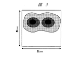
本発明の半導体デバイスの形状シミュレーション方法にかかる実施例1を、図1〜図8を用いて説明する。図1はCMPプロセスにおける研磨過程を説明するための、デバイスパターンの断面を示す説明図、図2および図3は局所的なパターン密度と平均化したパターン密度の概念を説明するための、デバイスパターンの上面を示す説明図、図4〜図8はパターンの拡張処理を説明するための、デバイスパターンの上面を示す説明図である。
Example 1
A first embodiment of the semiconductor device shape simulation method of the present invention will be described with reference to FIGS. FIG. 1 is an explanatory view showing a cross section of a device pattern for explaining a polishing process in the CMP process, and FIGS. 2 and 3 are device patterns for explaining the concept of local pattern density and averaged pattern density. FIG. 4 to FIG. 8 are explanatory views showing the upper surface of the device pattern for explaining the pattern expansion process.
まず、図1を用いて、CMPプロセスにおける研磨過程について説明する。CMPプロセスにおいては、研磨パッド13をデバイスの凸パターン15に押し当てて回転させ、デバイス表面上に存在する凸部分を研磨し、平坦化する。酸化膜CMPプロセスの場合、この凸パターン15は酸化膜でパターン11上に堆積された酸化膜12によって形成されている。従って、図1の通り、凸パターン15は必ずしもパターン11と一致しない。この際、研磨パッド13はデバイス表面上に存在する凸パターン15の影響を受けて変形を起こす。研磨パッド13は凸パターン15に接触するが、研磨パッド13の変形のために注目している凸パターン15上だけに応力が集中せずに、凸パターン15から遠方に向かってたわむ。
First, the polishing process in the CMP process will be described with reference to FIG. In the CMP process, the
この影響を考慮したシミュレーションを実行するため、通常は応力応答関数と呼ばれる関数によって局所的なパターン密度ρを平均化し、この平均化したパターン密度ρ’を求めることが行われる。ここで、局所的なパターン密度とは単位面積あたりに存在する凸パターン15の占める割合のことである。通常、上記単位面積は数μm×数μmの領域が占める面積であり、本実施例では25μm×25μm(=625μm2)である。局所的なパターン密度ρを求めるには、チップ(通常1辺数mmサイズの長方形もしくは正方形、数mm:1〜15mm程度)を上記で述べたような例えば25μm×25μmの領域に分割し、各分割領域での凸パターンが占める割合を求める。
In order to execute a simulation in consideration of this influence, the local pattern density ρ is usually averaged by a function called a stress response function, and the averaged pattern density ρ ′ is obtained. Here, the local pattern density is a ratio of the
図2、図3を用いて、局所的なパターン密度ρと平均化したパターン密度ρ’の概念を説明する。図2において、黒い部分のパターン21は凸パターンの局所的なパターン密度ρが80%を占めていることを示す。図2を平均化処理すると、図3のようにパターン21の輪郭がぼやけて密度の高い部分(灰色の濃い部分)と低い部分(灰色の薄い部分)の分布が発生することが分かる。このようにして、平均化したパターン密度ρ’のチップ内分布を求めることができる。
The concept of the local pattern density ρ and the averaged pattern density ρ ′ will be described with reference to FIGS. In FIG. 2, a
平均化したパターン密度ρ’を用いたCMPシミュレーション手法については現在までに多くの論文(例えば、前記非特許文献1など)が書かれているので、ここでは詳述しない。 Since many papers (for example, Non-Patent Document 1) have been written about the CMP simulation method using the averaged pattern density ρ ', it will not be described in detail here.
以上までで述べたとおり、図1においてチップ上に存在するパターン11の密度をそのまま求めたのでは酸化膜12の堆積を考慮したシミュレーションを実施することができず、酸化膜12の堆積した後の凸パターン15の密度を求める必要がある。設計CADデータのレベルではパターン11の情報しか含まれていないので、設計CADデータから酸化膜堆積後の凸パターン密度を求める方法について以下に述べる。
As described above, if the density of the
図1を見ると、パターン11の上に酸化膜12が覆いかぶさり、元々離れて存在していたパターン11の上に形成された凸パターン15は一つの大きな領域となっていることが分かる。ここで、図4のような単一のパターンを考えた場合に、パターンをδだけ周囲に向かって拡張させる(図5)。これにより、図6のような元のパターン(図4)よりも大きなパターンが得られる。図7のようにδ以内のスペースで、隣接する複数のパターンが存在する場合、上記に述べたようなパターンの拡張を実施すると図8のような連続した大きな凸パターン領域が得られる。このようなパターンの拡張処理は、市販されている多くのLSI設計ツールの機能として備わっており、容易に実施することができる。
Referring to FIG. 1, it can be seen that the
以上のようにして、本実施例によれば、元の設計CADデータを加工することにより、酸化膜堆積などのパターン形成後のプロセスによって生じる凸パターン領域を考慮したCMPシミュレーションが可能となる。 As described above, according to the present embodiment, by processing the original design CAD data, it is possible to perform a CMP simulation in consideration of a convex pattern region generated by a process after pattern formation such as oxide film deposition.
(実施例2)
本発明の半導体デバイスの形状シミュレーション方法にかかる実施例2を、図9を用いて説明する。図9は2種類以上の高さのパターンが同一のチップ上に存在する場合を説明するための、デバイスパターンの断面を示す説明図である。
(Example 2)
Example 2 according to the semiconductor device shape simulation method of the present invention will be described with reference to FIG. FIG. 9 is an explanatory diagram showing a cross-section of a device pattern for explaining a case where two or more types of height patterns exist on the same chip.
上記実施例1では、パターンの高さが1種類のみの例について説明したが、本実施例では2種類以上の高さのパターンが同一のチップ上に存在する場合について以下に説明する。 In the first embodiment, an example in which the pattern height is only one type has been described. In the present embodiment, a case in which two or more types of patterns exist on the same chip will be described below.
図9を用いて、二つの高さの異なるパターン91,92が形成された1つのチップの場合を説明する。それぞれのパターンの上には酸化膜が形成されており、酸化膜形成後のパターン高さはそれぞれ、高い方がt1、低い方がt2となっている。ここでは、パターンが存在しない部分の高さを基準、すなわちゼロとする。また、それぞれ二つの高さを持つパターンは互いに重なることはないものとする。この場合の局所的なパターン密度は、次の式を用いて求める。
The case of one chip on which two
ρ=ρ1+(t1/t2)ρ2 ・・・(1)
式(1)におけるρ1は高さt1の領域が単位面積あたりに占める割合、ρ2は高さt2の領域が単位面積あたりに占める割合である。式(1)で求めたρからρ’を求め、シミュレーションを実施することで、二つの段差を持つ場合の研磨後段差の評価が可能となる。なお、シミュレーションで必要になる初期段差としてはt2の値を用いる。
ρ = ρ1 + (t1 / t2) ρ2 (1)
In the formula (1), ρ1 is a ratio of the area of the height t1 per unit area, and ρ2 is a ratio of the area of the height t2 per unit area. By obtaining ρ ′ from ρ obtained by the equation (1) and performing a simulation, the post-polishing step difference can be evaluated when there are two step portions. Note that the value of t2 is used as the initial step required in the simulation.
以上のようにして、本実施例によれば、二つの高さが異なるパターンが存在するチップのCMPシミュレーションが可能となる。 As described above, according to this embodiment, it is possible to perform CMP simulation of a chip in which two patterns having different heights exist.
(実施例3)
本発明の半導体デバイスの形状シミュレーション方法にかかる実施例3を、図10を用いて説明する。図10は二つの高さの異なるパターンが重なり合う場合を説明するための、デバイスパターンの断面を示す説明図である。
(Example 3)
A third embodiment of the semiconductor device shape simulation method of the present invention will be described with reference to FIG. FIG. 10 is an explanatory view showing a cross section of a device pattern for explaining a case where two patterns having different heights overlap each other.
上記実施例2では、二つの高さの異なるパターンが重なり合わない場合について説明したが、本実施例では二つの高さの異なるパターンが重なり合う場合について以下に説明する。 In the second embodiment, a case where two patterns having different heights do not overlap has been described. In the present embodiment, a case where two patterns having different heights overlap will be described below.
図10を用いて、二つの高さの異なるパターン91,93が形成され、一部でパターン91とパターン93が重なり合う構造を持つチップの場合を説明する。また、パターン91同士は重なり合うことが無く、またパターン93同士も重なり合うことはないものとする。この場合、パターン91とパターン93が重なり合う領域の高さはt3(=t1+t2)となる。3つの高さの違うパターンを含む領域の局所的なパターン密度ρは次のようにして求める。
The case of a chip having a structure in which two
ρ=ρ3+ρ1(t2/t3)+ρ2(t1/t3) ・・・(2)
式(2)におけるρ1は高さt1の領域が単位面積あたりに占める割合、ρ2は高さt2の領域が単位面積あたりに占める割合、ρ3は高さt3の領域が単位面積あたりに占める割合である。式(2)で求めたρからρ’を求め、シミュレーションを実施することで二つの段差を持つ場合の研磨後段差の評価が可能となる。なお、シミュレーションで必要になる初期段差としてはt3の値を用いる。
ρ = ρ3 + ρ1 (t2 / t3) + ρ2 (t1 / t3) (2)
In equation (2), ρ1 is the ratio of the area of height t1 per unit area, ρ2 is the ratio of the area of height t2 per unit area, and ρ3 is the ratio of the area of height t3 per unit area. is there. By obtaining ρ ′ from ρ obtained by the equation (2) and performing a simulation, the post-polishing step difference can be evaluated. Note that the value of t3 is used as the initial step required in the simulation.
以上のようにして、本実施例によれば、二つの高さが異なるパターンが混在し、かつ重なり合う構造のチップにおいてCMPシミュレーションが可能となる。 As described above, according to the present embodiment, CMP simulation can be performed on chips having a structure in which two patterns having different heights are mixed and overlapped.
また、本実施例において、パターン91同士が重なり合う場合、およびパターン93同士が重なり合う場合においては、次のような取り扱いをすればよい。また、ここで最も高くなる場所はパターン93同士が重なり合う場所であり、高さがt5となるものとする。ここで、局所的なパターン密度ρは次のようにして求める。また、パターン91同士が重なり合う場所の高さはt4とする。
In the present embodiment, when the
ρ=ρ5+ρ1(t2/t5)+ρ2(t1/t5)
+ρ3(t3/t5)+ρ4(t3/t4) ・・・(3)
式(3)におけるρ5はパターン93同士が重なり合う場所が単位面積あたりに占める割合であり、ρ4はパターン91同士が重なり合う場所が単位面積あたりに占める割合である。
ρ = ρ5 + ρ1 (t2 / t5) + ρ2 (t1 / t5)
+ Ρ3 (t3 / t5) + ρ4 (t3 / t4) (3)
In Expression (3), ρ5 is a ratio of the area where the
以上のようにして、本実施例によれば、二つの高さが異なるパターンが混在し、かつ重なり合う構造のチップにおいてCMPシミュレーションが可能となる。 As described above, according to the present embodiment, CMP simulation can be performed on chips having a structure in which two patterns having different heights are mixed and overlapped.
(実施例4)
本発明の半導体デバイスの形状シミュレーション方法にかかる実施例4を、図11および図12を用いて説明する。図11および図12はパターン上にオゾン−TEOS法やPSG法などで形成された酸化膜を堆積した場合を説明するための、デバイスパターンの断面を示す説明図である。
Example 4
Example 4 according to the semiconductor device shape simulation method of the present invention will be described with reference to FIGS. 11 and 12 are explanatory views showing a cross section of a device pattern for explaining a case where an oxide film formed by an ozone-TEOS method or a PSG method is deposited on the pattern.
本実施例では、パターン上にオゾン−TEOS(TetraEthylOrthoSilicate)法やPSG(Phosphosilicate Glass)法などで形成された酸化膜を堆積した場合について、図11、図12を用いて以下に説明する。 In this embodiment, the case where an oxide film formed by an ozone-TEOS (Tetra Ethyl Ortho Silicate) method or a PSG (Phosphosilicate Glass) method is deposited on a pattern will be described below with reference to FIGS.
オゾン−TEOS法で形成した酸化膜151は、図11のように元々存在するパターン11に対してコンフォーマルに堆積する性質がある。このため、膜厚をDとした場合に、図11にハッチングで示した領域153がパターンから見て四分円状になる。この四分円状の領域153を拡大して図示したものが図12である。四分円であるから領域153の断面積は(1/4)πD2である。ここで、この四分円の領域153と同じ面積で高さDとなる長方形の短辺の長さを求めると(π/4)Dとなる。コンフォーマルに堆積する酸化膜によって(π/4)Dだけパターンの幅が広くなると仮定すれば、図5におけるδの値を(π/4)Dとしてパターン密度を求めればよいことになる。
The
以上のようにして、本実施例によれば、オゾン−TEOS法やPSG法などの酸化膜による堆積の効果を考慮したシミュレーションが可能となる。 As described above, according to this embodiment, it is possible to perform a simulation in consideration of the effect of deposition by an oxide film such as an ozone-TEOS method or a PSG method.
(実施例5)
本発明の半導体デバイスの形状シミュレーション方法にかかる実施例5を、図13および図14を用いて説明する。図13および図14はパターン上にHDP法やこれに類する方法で形成された酸化膜を堆積した場合を説明するための、デバイスパターンの断面を示す説明図である。
(Example 5)
Example 5 of the semiconductor device shape simulation method of the present invention will be described with reference to FIGS. 13 and 14. FIG. FIG. 13 and FIG. 14 are explanatory views showing a cross section of a device pattern for explaining a case where an oxide film formed by the HDP method or a similar method is deposited on the pattern.
本実施例では、パターン上にHDP(High Density Plasma)法やこれに類する方法で形成された酸化膜を堆積した場合について、図13、図14を用いて以下に説明する。 In this embodiment, the case where an oxide film formed by an HDP (High Density Plasma) method or a similar method is deposited on a pattern will be described below with reference to FIGS.
HDP法で形成した酸化膜181は、図13のように元々存在するパターン11の端部が三角形状に切り取られた形状となる。このため、膜厚をDとした場合に、図13にハッチングで示した領域183がパターンから見て三角形になる。この三角形の領域183を拡大して図示したものが図14である。この三角形は通常のHDPプロセスの場合、二等辺直角三角形となる。この三角形の断面積は(1/2)D2である。ここで、この三角形の領域183と同じ面積で高さDとなる長方形の短辺の長さを求めるとD/2となる。HDP膜によってD/2だけパターンの幅が広くなると仮定すれば、図5におけるδの値を−D/2としてパターン密度を求めればよいことになる。ただし、HDP膜の場合、実測との適合性を高めるためにδの値を−D/4〜−Dとしても良い。
The
以上のように、本実施例によれば、HDP法やこれに類する方法によって堆積した酸化膜の効果を考慮したシミュレーションが可能となる。 As described above, according to the present embodiment, it is possible to perform a simulation in consideration of the effect of an oxide film deposited by the HDP method or a similar method.
(実施例6)
本発明の半導体デバイスの形状シミュレーション方法にかかる実施例6を、図15および図16を用いて説明する。図15および図16はパターン上の酸化膜をエッチングした場合を説明するための、デバイスパターンの断面を示す説明図である。
(Example 6)
A sixth embodiment of the semiconductor device shape simulation method of the present invention will be described with reference to FIGS. FIG. 15 and FIG. 16 are explanatory views showing a cross section of a device pattern for explaining a case where an oxide film on the pattern is etched.
本実施例では、パターン上の酸化膜をエッチングした場合について、図15、図16を用いて以下に説明する。 In this embodiment, the case where the oxide film on the pattern is etched will be described below with reference to FIGS.
図15は、パターン11の上に酸化膜12を形成した後の断面形状の概略図を示したものである。ここで、堆積した酸化膜12の厚さはTd[nm]であり、凸パターン15がパターン11上に形成される。また、図16は、図15で形成された酸化膜12をエッチングにより凸パターン15の一部だけを掘り下げたものである。エッチングにより掘り下げる深さはE[nm]である。ここで、図16における局所的なパターン密度ρを次のように表現することにする。
FIG. 15 shows a schematic diagram of a cross-sectional shape after the
ρ=ρN+ρE(Td−E)/Td ・・・(4)
式(4)におけるρNはエッチングされていない凸パターンの単位面積あたりの割合であり、ρEはエッチングされている領域の単位面積あたりの割合である。上記の取り扱いにより、エッチングされた部分の体積を考慮したパターン密度ρを求めることができる。このρを応力応答関数により平均化してρ’を求めれば、CMPシミュレーションに利用することができる。
ρ = ρN + ρE (Td−E) / Td (4)
In Expression (4), ρN is a ratio per unit area of the unetched convex pattern, and ρE is a ratio per unit area of the etched region. By the above handling, the pattern density ρ in consideration of the volume of the etched portion can be obtained. If this ρ is averaged by a stress response function to obtain ρ ′, it can be used for CMP simulation.
以上のように、本実施例によれば、パターン上の酸化膜をエッチングした場合についてもCMPシミュレーションを実施することが可能となる。 As described above, according to the present embodiment, it is possible to carry out the CMP simulation even when the oxide film on the pattern is etched.
以上、本発明者によってなされた発明を実施の形態に基づき具体的に説明したが、本発明は前記実施の形態に限定されるものではなく、その要旨を逸脱しない範囲で種々変更可能であることはいうまでもない。 As mentioned above, the invention made by the present inventor has been specifically described based on the embodiment. However, the present invention is not limited to the embodiment, and various modifications can be made without departing from the scope of the invention. Needless to say.
本発明は、半導体デバイスの製造技術に関し、特に、半導体デバイスの表面をCMPにより研磨した後の表面形状を予測するシミュレーション方法に適用して有効である。 The present invention relates to a semiconductor device manufacturing technique, and is particularly effective when applied to a simulation method for predicting a surface shape after the surface of a semiconductor device is polished by CMP.
11…パターン、12…酸化膜、13…研磨パッド、15…凸パターン、21…パターン、91…パターン、92…パターン、93…パターン、151…酸化膜、153…領域、181…酸化膜、183…領域。
DESCRIPTION OF
Claims (9)
設計CADデータからCMP研磨前に堆積する膜の影響を考慮するため、設計CADデータ中のパターンが占める割合を変化させて、CMP研磨後の膜厚シミュレーションを実施することを特徴とする半導体デバイスの形状シミュレーション方法。 A semiconductor device shape simulation method using a computer for predicting a surface shape after polishing the surface of a semiconductor device by CMP,
In order to consider the influence of the film deposited before CMP polishing from the design CAD data, a ratio of the pattern in the design CAD data is changed, and a film thickness simulation after CMP polishing is performed. Shape simulation method.
前記CMP研磨後の膜厚シミュレーションを実施する際には、設計CADデータ中のパターン幅を増大もしくは減少させ、単位面積あたりのパターン幅を増大もしくは減少させたパターンの占める割合を求め、この割合を用いてCMP研磨後の膜厚シミュレーションを実施することを特徴とする半導体デバイスの形状シミュレーション方法。 In the semiconductor device shape simulation method according to claim 1,
When performing the film thickness simulation after the CMP polishing, the pattern width in the design CAD data is increased or decreased, and the ratio of the pattern that increases or decreases the pattern width per unit area is obtained. A method for simulating the shape of a semiconductor device, wherein the simulation of film thickness after CMP polishing is performed.
前記設計CADデータ中には、高さの異なる二種類以上のパターンが含まれており、この二種類以上の異なる高さを考慮してCMP研磨後の膜厚シミュレーションを実施することを特徴とする半導体デバイスの形状シミュレーション方法。 In the semiconductor device shape simulation method according to claim 1 or 2,
The design CAD data includes two or more patterns having different heights, and a film thickness simulation after CMP polishing is performed in consideration of the two or more different heights. Semiconductor device shape simulation method.
前記高さの異なる二種類以上のパターンには、t1なる高さとt2(t1>t2)なる高さの二種類の異なるパターンが存在し、この二種類のパターンが同じ領域を占めることがない場合、t1の高さを持つパターンもしくはt1のパターン上の堆積膜の占める面積の割合をρ1とし、t2の高さを持つパターンもしくはt2のパターン上の堆積膜の占める面積の割合をρ2とした場合、新たにパターンが単位面積あたりに占める面積の割合をρ1+(t1/t2)ρ2として求めることを特徴とする半導体デバイスの形状シミュレーション方法。 In the semiconductor device shape simulation method according to claim 3,
The two or more types of patterns having different heights include two different types of patterns having a height of t1 and a height of t2 (t1> t2), and these two types of patterns do not occupy the same region. , The ratio of the area occupied by the pattern having the height of t1 or the deposited film on the pattern of t1 is ρ1, and the ratio of the area occupied by the deposited film on the pattern having the height of t2 or the pattern of t2 is ρ2. A method for simulating the shape of a semiconductor device, wherein the ratio of the area occupied by a pattern per unit area is newly obtained as ρ1 + (t1 / t2) ρ2.
前記高さの異なる二種類以上のパターンには、t1なる高さとt2(t1>t2)なる高さの二種類の異なるパターンが存在し、このt1なる高さを持つパターンとt2なる高さを持つパターンが重なる場合、重なった部分の高さをt3とし、重なった部分のパターンもしくは重なった部分のパターン上の堆積膜の占める面積の割合をρ3とした場合、新たにパターンが単位面積あたりに占める面積の割合をρ3+ρ1(t2/t3)+ρ2(t1/t3)として求めることを特徴とする半導体デバイスの形状シミュレーション方法。 In the semiconductor device shape simulation method according to claim 3,
The two or more types of patterns having different heights include two different types of patterns having a height of t1 and a height of t2 (t1> t2), and a pattern having a height of t1 and a height of t2. If the overlapping patterns are overlapped, the height of the overlapped portion is t3, and the ratio of the area occupied by the deposited film on the overlapped portion pattern or the overlapped portion pattern is ρ3, the pattern is newly added per unit area. A method for simulating the shape of a semiconductor device, wherein the ratio of the occupied area is calculated as ρ3 + ρ1 (t2 / t3) + ρ2 (t1 / t3).
前記CMP研磨後の膜厚シミュレーションを実施する際には、CMP前に堆積する酸化膜がオゾン−TEOS法もしくはこれに類するコンフォーマルな堆積形状を特徴とする方法により堆積された際、堆積したオゾン−TEOS膜もしくはこれに類する膜の堆積厚さをDとしたとき、(π/4)Dだけ設計CADデータ中のパターン幅を増大させ、このパターン幅を増大させたCADデータから単位面積あたりのパターン幅を増大させたパターンの占める割合を求め、この割合を用いてCMP研磨後の膜厚シミュレーションを実施することを特徴とする半導体デバイスの形状シミュレーション方法。 In the shape simulation method of the semiconductor device according to any one of claims 1 to 5,
When performing the film thickness simulation after the CMP polishing, the deposited ozone film is deposited when the oxide film deposited before CMP is deposited by the ozone-TEOS method or a method characterized by a conformal deposition shape similar thereto. -When the deposition thickness of the TEOS film or a similar film is D, the pattern width in the design CAD data is increased by (π / 4) D, and the CAD data per unit area is increased from the CAD data with the increased pattern width. A method for simulating a shape of a semiconductor device, wherein a ratio of a pattern with an increased pattern width is obtained, and a film thickness simulation after CMP polishing is performed using this ratio.
前記CMP研磨後の膜厚シミュレーションを実施する際には、CMP前に堆積する酸化膜がHDP法により堆積された際、堆積したHDP膜の堆積厚さをDとしたとき、D/4〜Dの値だけ設計CADデータ中のパターン幅を縮小させ、このパターン幅を縮小させたCADデータから単位面積あたりのパターン幅を縮小させたパターンの占める割合を求め、この割合を用いてCMP研磨後の膜厚シミュレーションを実施することを特徴とする半導体デバイスの形状シミュレーション方法。 In the shape simulation method of the semiconductor device according to any one of claims 1 to 5,
When performing the film thickness simulation after CMP polishing, when an oxide film deposited before CMP is deposited by the HDP method, D / 4 to D, where D is the deposited thickness of the deposited HDP film The pattern width in the design CAD data is reduced by the value of this, and the ratio of the pattern with the reduced pattern width per unit area is obtained from the CAD data with the reduced pattern width. A method for simulating the shape of a semiconductor device, comprising performing a film thickness simulation.
前記CMP研磨後の膜厚シミュレーションを実施する際には、設計CADデータを用いてCMP前に堆積する酸化膜もしくはその他の膜の体積を求め、さらに堆積後のエッチング処理によって変化した体積を求め、この体積を考慮してCMP研磨後の膜厚シミュレーションを実施することを特徴とする半導体デバイスの形状シミュレーション方法。 In the semiconductor device shape simulation method according to any one of claims 1 to 7,
When performing the film thickness simulation after CMP polishing, the design CAD data is used to determine the volume of the oxide film or other film deposited before CMP, and further the volume changed by the etching process after deposition is determined, A semiconductor device shape simulation method, wherein a film thickness simulation after CMP polishing is performed in consideration of the volume.
堆積した酸化膜の厚さがTdであり、エッチング処理により減少した部分の厚さがTd−Eであるとき、エッチング処理が施された部分が占める単位面積あたりの割合をρE、エッチング処理が施されていない部分でかつパターン上に凸状に形成された堆積膜が占める単位面積あたりの割合をρNとするとき、新たに単位面積あたりのパターンの占める割合をρN+ρE(Td−E)/Tdとして求め、このパターンの占める割合を用いてCMP研磨後の膜厚シミュレーションを実施することを特徴とする半導体デバイスの形状シミュレーション方法。 The shape simulation method for a semiconductor device according to claim 8,
When the thickness of the deposited oxide film is Td and the thickness of the portion reduced by the etching treatment is Td-E, the ratio per unit area occupied by the etched portion is ρE, and the etching treatment is performed. Assuming that the ratio per unit area occupied by the deposited film formed in a convex pattern on the pattern is ρN, the ratio of the pattern per unit area is newly defined as ρN + ρE (Td−E) / Td. A method for simulating the shape of a semiconductor device, characterized in that a film thickness simulation after CMP polishing is performed using the ratio of the pattern.
Priority Applications (1)
| Application Number | Priority Date | Filing Date | Title |
|---|---|---|---|
| JP2005291004A JP2007103634A (en) | 2005-10-04 | 2005-10-04 | Shape simulation method of semiconductor device |
Applications Claiming Priority (1)
| Application Number | Priority Date | Filing Date | Title |
|---|---|---|---|
| JP2005291004A JP2007103634A (en) | 2005-10-04 | 2005-10-04 | Shape simulation method of semiconductor device |
Publications (1)
| Publication Number | Publication Date |
|---|---|
| JP2007103634A true JP2007103634A (en) | 2007-04-19 |
Family
ID=38030281
Family Applications (1)
| Application Number | Title | Priority Date | Filing Date |
|---|---|---|---|
| JP2005291004A Pending JP2007103634A (en) | 2005-10-04 | 2005-10-04 | Shape simulation method of semiconductor device |
Country Status (1)
| Country | Link |
|---|---|
| JP (1) | JP2007103634A (en) |
Cited By (2)
| Publication number | Priority date | Publication date | Assignee | Title |
|---|---|---|---|---|
| US8117568B2 (en) | 2008-09-25 | 2012-02-14 | International Business Machines Corporation | Apparatus, method and computer program product for fast simulation of manufacturing effects during integrated circuit design |
| US8490031B2 (en) | 2009-05-20 | 2013-07-16 | Sony Corporation | Method, apparatus and program for adjusting feature dimensions to compensate for planarizing effects in the generation of mask data and manufacturing semiconductor device |
-
2005
- 2005-10-04 JP JP2005291004A patent/JP2007103634A/en active Pending
Cited By (2)
| Publication number | Priority date | Publication date | Assignee | Title |
|---|---|---|---|---|
| US8117568B2 (en) | 2008-09-25 | 2012-02-14 | International Business Machines Corporation | Apparatus, method and computer program product for fast simulation of manufacturing effects during integrated circuit design |
| US8490031B2 (en) | 2009-05-20 | 2013-07-16 | Sony Corporation | Method, apparatus and program for adjusting feature dimensions to compensate for planarizing effects in the generation of mask data and manufacturing semiconductor device |
Similar Documents
| Publication | Publication Date | Title |
|---|---|---|
| US7509622B2 (en) | Dummy filling technique for improved planarization of chip surface topography | |
| US9223924B2 (en) | Method and system for multi-patterning layout decomposition | |
| TW201730797A (en) | Method multi-patterning | |
| US8129095B2 (en) | Methods, photomasks and methods of fabricating photomasks for improving damascene wire uniformity without reducing performance | |
| KR20140029050A (en) | Method of forming pattern | |
| US7569842B2 (en) | Method for correcting electron beam exposure data | |
| JP2007103634A (en) | Shape simulation method of semiconductor device | |
| JP3934919B2 (en) | Mask blank selection method, exposure mask formation method, and semiconductor device manufacturing method | |
| JP2008098588A (en) | Method of extracting hot spot in layout designing/verification of semiconductor device | |
| US8499259B2 (en) | Polishing estimation/evaluation device, overpolishing condition calculation device, and computer-readable non-transitory medium thereof | |
| JP3703799B2 (en) | Remaining film thickness distribution estimation method, patterning mask and insulating film removal mask correction method using residual film thickness distribution estimation method, and semiconductor element using modified patterning mask and insulating film removal mask Manufacturing method | |
| US10176290B2 (en) | Manufacturing method for a semiconductor device, pattern generating method and nontransitory computer readable medium storing a pattern generating program | |
| CN108228954A (en) | Method for distributing coloring pattern | |
| JP2009182056A (en) | Semiconductor device design method, design apparatus, and program | |
| JP2008020734A (en) | Design pattern preparation method for semiconductor device, program, and method of manufacturing the semiconductor device | |
| JP3947154B2 (en) | Mask substrate information generation method and mask substrate manufacturing method | |
| JP2005079392A (en) | Method for generating image drawing data | |
| JP3553053B2 (en) | Method for estimating residual film thickness distribution, method for designing mask for patterning using method for estimating residual film thickness distribution, and method for designing semiconductor device using mask for patterning designed using method for estimating residual film thickness distribution Production method | |
| JP3984278B2 (en) | Mask substrate flatness simulation system | |
| JP3947177B2 (en) | Mask substrate flatness simulation system | |
| JP5924029B2 (en) | Design support apparatus, design support method, and program | |
| JP2006179816A (en) | Method for automatically designing semiconductor integrated circuit | |
| JP3447621B2 (en) | Generation method of flattening pattern | |
| JP3725149B2 (en) | Manufacturing method of mask substrate | |
| JP4025351B2 (en) | Mask substrate information generation method, mask substrate manufacturing method, and mask substrate inspection method |