JP2007077458A - Vacuum deposition equipment - Google Patents
Vacuum deposition equipment Download PDFInfo
- Publication number
- JP2007077458A JP2007077458A JP2005267888A JP2005267888A JP2007077458A JP 2007077458 A JP2007077458 A JP 2007077458A JP 2005267888 A JP2005267888 A JP 2005267888A JP 2005267888 A JP2005267888 A JP 2005267888A JP 2007077458 A JP2007077458 A JP 2007077458A
- Authority
- JP
- Japan
- Prior art keywords
- lid
- vapor deposition
- deposition material
- material container
- crucible
- Prior art date
- Legal status (The legal status is an assumption and is not a legal conclusion. Google has not performed a legal analysis and makes no representation as to the accuracy of the status listed.)
- Granted
Links
Images
Landscapes
- Physical Vapour Deposition (AREA)
Abstract
【課題】 蒸着材料を入れたルツボ6の蓋11を真空雰囲気でも開閉することを可能とし、放熱ロスを抑制することを可能とする。
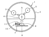
【解決手段】 被蒸着フィルム3を支持して走行させるコーティングローラ4の直下に置かれるルツボ6を、蒸着のための作動位置と清掃等のための退避位置に容器移動手段によって移動させる構成とし、そのルツボ6の移動に連動して且つルツボ6の移動を駆動源として蓋11を開閉させる蓋開閉手段12を設け、ルツボ6が作動位置にある時は蓋11を開位置とし、退避位置に移動した時には閉位置となるようにする。
【選択図】 図1PROBLEM TO BE SOLVED: To open and close a lid 11 of a crucible 6 containing a vapor deposition material even in a vacuum atmosphere and to suppress a heat dissipation loss.
A crucible 6 placed immediately below a coating roller 4 that supports and travels a film to be deposited 3 is moved by a container moving means to an operation position for vapor deposition and a retreat position for cleaning, etc. Lid opening / closing means 12 is provided to open and close the lid 11 in conjunction with the movement of the crucible 6 and using the movement of the crucible 6 as a drive source. When the crucible 6 is in the operating position, the lid 11 is opened and moved to the retracted position. When closed, it should be in the closed position.
[Selection] Figure 1
Description
本発明は、合成樹脂フィルム等の被蒸着フィルムに、アルミ(Al)、酸化シリコン(SiO)等の蒸着材料を蒸着させるための真空蒸着装置の技術分野に属するものである。 The present invention belongs to the technical field of a vacuum deposition apparatus for depositing a deposition material such as aluminum (Al) or silicon oxide (SiO) on a film to be deposited such as a synthetic resin film.
食品等の物を包装あるいは収納するために、従来から各種の合成樹脂フィルムが使用されており、また、ガスバリア性を高めるため、合成樹脂フィルムにアルミニウムや酸化物を蒸着させて形成した積層樹脂フィルムも多く使用されている。特に、酸化物を蒸着した積層樹脂フィルムは、ガスバリア性を確保しながら、マイクロ波を透過させることができるので、電子レンジ等で使用することができる利点を有しており、最近使用量が増大している。この積層樹脂フィルムに用いる金属酸化物としては、酸化アルミ(AlOX )が最も適しており、多く使用されている。しかも、この酸化アルミが蒸着された積層樹脂フィルムは廃棄処理時に分別する必要がないので、廃棄処理作業が簡単になり、環境上もきわめて有効となっている。 Various synthetic resin films have been used to wrap or store foods, etc., and a laminated resin film formed by depositing aluminum or oxide on a synthetic resin film to improve gas barrier properties. Many are also used. In particular, laminated resin films deposited with oxides have the advantage that they can be used in microwave ovens and the like because they can transmit microwaves while ensuring gas barrier properties. is doing. As the metal oxide used for the laminated resin film, aluminum oxide (AlO x ) is most suitable and is often used. In addition, since the laminated resin film on which the aluminum oxide is deposited does not need to be separated at the time of disposal, the disposal process is simplified and the environment is extremely effective.
合成樹脂フィルムに対する蒸着には、一般に真空での物理蒸着による真空蒸着法が採用されている。従来の真空蒸着装置では、真空チャンバー内に形成された真空内において、セラミック等よりなる上面に開口を有するルツボの中に入れられたアルミ、SiO等の蒸着材料に電子ビーム等により熱を加えて蒸発させ、その上方をコーティングローラによって支持されて走行している合成樹脂フィルム等の被蒸着フィルムに蒸着材料を薄膜状に付着させる動作が行われている(特許文献1参照)。また、酸化アルミを蒸着させる場合には、アルミ蒸気中に酸素を吹き込んで酸化させる方法が取られている。 For vapor deposition on a synthetic resin film, a vacuum vapor deposition method by physical vapor deposition in vacuum is generally employed. In a conventional vacuum deposition apparatus, heat is applied by an electron beam or the like to a deposition material such as aluminum or SiO placed in a crucible having an opening on the upper surface made of ceramic or the like in a vacuum formed in a vacuum chamber. An operation of evaporating and adhering a vapor deposition material in a thin film form to a film to be vapor deposited such as a synthetic resin film supported by a coating roller on the upper side is performed (see Patent Document 1). In the case of depositing aluminum oxide, a method of oxidizing by blowing oxygen into aluminum vapor is employed.
被蒸着フィルムは巻取りの形態でセットされ、コーティングローラによって支持されて走行しながら蒸着材料の蒸気にさらされ、連続的に蒸着が行われ、蒸着済の積層樹脂フィルムも巻取りの形態に巻き取られる。セットされた被蒸着フィルムを使い切ると、走行を止め、真空を解除して、被蒸着フィルムや積層樹脂フィルムをかけ替える必要が生じる。被蒸着フィルムや積層樹脂フィルムのかけ替え中は、ルツボ及びその中の蒸着材料が大気中にさらされ、放熱が起こるため、熱ロスを抑える目的で酸化アルミなどの蓋を被せることが一般に行われている。この作業は人手で行われるのが普通であるため、真空チャンバー内が完全に大気状態で且つ開放されていなければならず、大気導入中や、その後の真空引き中は蓋をすることができず、その間における放熱を抑えることができないという問題があった。
本発明はかかる問題点に鑑みてなされたもので、蒸着材料を入れた蒸着材料容器に対して真空雰囲気中においても蓋をすることを可能とし、放熱ロスを抑制する事の可能な真空蒸着装置を提供することを課題とする。 The present invention has been made in view of such problems, and it is possible to cover a vapor deposition material container containing a vapor deposition material even in a vacuum atmosphere and to suppress heat dissipation loss. It is an issue to provide.
上記した課題を解決するため、本願請求項1に係る発明は、上面に開口を有し、蒸着材料を収容して該蒸着材料を上方に向かって蒸発させることの可能な蒸着材料容器と、この蒸着材料容器を、真空蒸着のための作動位置と退避位置との間でほぼ水平に往復移動させる容器移動手段と、前記蒸着材料容器の上面の開口を閉じるように設けられた蓋と、前記蒸着材料容器の移動に連動して前記蓋を開閉させる蓋開閉手段を備え、該蓋開閉手段は、前記蒸着材料容器が退避位置に移動した時に前記蓋を前記蒸着材料容器に対する閉位置とし、作動位置に移動した時に前記蓋を前記蒸着材料容器に対する開位置とする構成であることを特徴とする真空蒸着装置を要旨とする。
In order to solve the above-described problem, the invention according to
ここで、前記蓋開閉手段は、前記蓋を前記蒸着材料容器の上面に沿って往復移動するように案内する蓋移動用ガイドと、前記蓋を開方向に付勢するばねと、前記蒸着材料容器が作動位置から退避位置に移動する方向に関して前記退避位置よりも前に設定した位置にほぼ垂直に設けられた回転軸と、該回転軸と一緒に回転するように取り付けられた第一レバー及び第二レバーを有し、前記第一レバーは前記蒸着材料容器が作動位置から退避位置に移動する際に前記蒸着材料容器で押されて第一方向に旋回するように配置されており、前記第二レバーは、前記第一レバーが第一方向に旋回した時に一緒に第一方向に旋回し、前記蓋を前記蒸着材料容器に対して開方向に押すように配置されている構成とすることが好ましい。 Here, the lid opening / closing means includes a lid moving guide that guides the lid to reciprocate along the upper surface of the vapor deposition material container, a spring that biases the lid in the opening direction, and the vapor deposition material container A rotating shaft provided substantially perpendicular to a position set before the retracted position with respect to the direction in which the actuator moves from the operating position to the retracted position, and a first lever and a first lever attached to rotate together with the rotating shaft The first lever is arranged to be pushed by the vapor deposition material container and pivot in the first direction when the vapor deposition material container moves from the operating position to the retracted position. It is preferable that the lever is arranged so as to turn together in the first direction when the first lever turns in the first direction and push the lid in the opening direction with respect to the vapor deposition material container. .
また、前記蓋開閉手段は、前記蒸着材料容器の長手方向の両端領域にそれぞれ設けられている構成とすることが好ましい。 Further, it is preferable that the lid opening / closing means is provided in both end regions in the longitudinal direction of the vapor deposition material container.
このように構成された本発明の真空蒸着装置では、所定の蒸着動作が終了した後、容器移動手段によって蒸着材料容器を退避位置に移動させると、蓋開閉手段が蒸着材料容器の移動に連動して前記蓋を蒸着材料容器に対する閉位置に移動させ、また、蒸着材料容器を作動位置に移動させると、蓋開閉手段が蒸着材料容器の移動に連動して前記蓋を蒸着材料容器に対する開位置に移動させ、従って、蓋の開閉を蒸着材料容器の移動を利用して遠隔操作することができ、蒸着材料容器を設けている雰囲気内が真空であっても、また大気導入中や、その後の真空引き中であっても蓋の開閉を行うことができ、放熱を抑えて再加熱時間の縮小と熱ロスの削減を実現することができる。 In the vacuum vapor deposition apparatus of the present invention configured as described above, when the vapor deposition material container is moved to the retracted position by the container moving means after the predetermined vapor deposition operation is completed, the lid opening / closing means is interlocked with the movement of the vapor deposition material container. When the lid is moved to the closed position with respect to the vapor deposition material container, and the vapor deposition material container is moved to the operating position, the lid opening / closing means moves the vapor deposition material container to move the lid to the open position with respect to the vapor deposition material container. Therefore, the lid can be opened and closed remotely using the movement of the vapor deposition material container. Even if the atmosphere in which the vapor deposition material container is provided is vacuum, the vacuum is introduced during or after the introduction of air. Even during pulling, the lid can be opened and closed, reducing heat dissipation and reducing heat loss and heat loss.
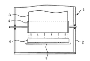
以下、図面を参照して本発明の実施の形態を説明する。図1は、本発明の実施の形態に係る真空蒸着装置を模式的に示す概略断面図、図2は図1のA−Aに沿う概略断面図である。図1、図2において、1は真空蒸着装置、2は内部を真空雰囲気にすることの可能な真空チャンバー、3は巻取りローラに巻かれた合成樹脂フィルムからなる被蒸着フィルム、4は蒸着材料蒸気を蒸着させる位置で被蒸着フィルム3をガイドするコーティングローラ、5は蒸着を終わって巻取りローラに巻かれた積層樹脂フィルム、6は、上面に開口を有し、アルミ等の蒸着材料を収容して該蒸着材料を上方に向かって蒸発させることの可能な蒸着材料容器すなわちルツボ、7はそのルツボ6を支持した支持台である。
Embodiments of the present invention will be described below with reference to the drawings. FIG. 1 is a schematic cross-sectional view schematically showing a vacuum vapor deposition apparatus according to an embodiment of the present invention, and FIG. 2 is a schematic cross-sectional view taken along A-A in FIG. 1 and 2, 1 is a vacuum deposition apparatus, 2 is a vacuum chamber in which the inside can be made into a vacuum atmosphere, 3 is a film to be deposited comprising a synthetic resin film wound around a take-up roller, and 4 is a deposition material Coating roller that guides the film to be deposited 3 at the position where vapor is deposited, 5 is a laminated resin film wound on a take-up roller after vapor deposition, and 6 has an opening on the upper surface and accommodates a deposition material such as aluminum. A vapor deposition material container, that is, a
ルツボ6は、平面形状が細長い矩形状をしており、その長手方向がコーティングローラ4の軸線方向に平行となるように配置されている。以下、平面内でルツボ6の長手方向に直角な方向を横方向と称する。ルツボ6は支持台7に対して横方向にほぼ水平に移動可能に保持されており、コーティングローラ4の直下に位置した真空蒸着のための作動位置と、その横方向の清掃等のための退避位置とに移動可能である。更に、図示は省略しているが、ルツボ6を真空蒸着のための作動位置と退避位置との間でほぼ水平に往復移動させる容器移動手段も設けられている。
The
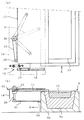
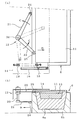
ルツボ6の上面には、ルツボ6上面の開口を閉じるように蓋11が設けられ、更に、その蓋11をルツボ6の移動に連動して且つルツボ6の移動を駆動源として開閉させる蓋開閉手段12も設けられている。以下、図3、図4を用いてその蓋開閉手段12を説明する。図3は、図1に示す真空蒸着装置のルツボ6の端部近傍を、ルツボ6を作動位置に位置させ、蓋11を開位置とした状態で示すもので、(a)は概略平面図、(b)は概略断面図、図4はルツボ6の端部近傍を、ルツボ6を退避位置に位置させ、蓋11を閉位置とした状態で示すもので、(a)は概略平面図、(b)は概略断面図である。ルツボ6は、蒸着材料13を収容するセラミック製等のルツボ本体6aと、冷却ケース6bを有している。
A
蓋開閉手段12は、ルツボ6が図4に示す退避位置に移動した時に蓋11をルツボ6に対する閉位置に移動させ、図3に示す作動位置に移動した時に蓋11をルツボ6に対する開位置に移動させる構成のものである。この実施の形態に用いている蓋開閉手段12は、支持台12に適当な支持部材(図示せず)によって取り付けられた支持板14と、その支持板14に取り付けられ、蓋11の端面に取り付けられたコロ15をガイドすることで蓋11をルツボ6の上面に沿ってルツボ6の横方向に往復移動可能に案内する蓋移動ガイド16と、蓋11を開方向に付勢するばね18と、ルツボ6を作動位置から退避位置に移動する方向〔図4(b)の矢印B方向〕に関して退避位置よりも前に設定した位置にほぼ垂直に設けられ、支持板14に回転可能に保持された回転軸20と、その回転軸20と一緒に回転するように取り付けられた第一レバー21及び第二レバー22を有している。
The lid opening / closing means 12 moves the
図4において、第一レバー21は先端にコロ24を備えており、ルツボ6が作動位置から退避位置に移動する際(矢印B方向に移動する際)、そのコロ24がルツボ6の側面で押されて第一レバー21が矢印Cで示す第一方向に旋回するように、配置されている。第二レバー22は先端にコロ25を備えており、第一レバー21が矢印Cで示す第一方向に旋回した時に一緒に矢印Cで示す第一方向に旋回し、コロ25で蓋11の側面を押し、蓋11を閉方向に押すことができる位置に配置されている。
In FIG. 4, the
蓋開閉手段12は、ルツボ6の両端領域に設けられており、蓋11の両端をばね18で引張って蓋11を開位置に移動させ、また、蓋11の両端を第二レバー22で押して蓋11を閉位置に移動させるようになっている。
The lid opening /
次に、上記構成の真空蒸着装置1の動作を説明する。蒸着操作を行う際には、図1に示すように、ルツボ6はコーティングローラ4の直下に位置した真空蒸着のための作動位置に位置している。この時、図3に示すように、蓋11はばね18で引っ張られて、ルツボ6の上面の開口を開放した開位置に位置している。なお、第二レバー22は蓋11が開く時にその蓋11で押されて図示した位置に旋回するが、蓋11が開位置に達した時には、第一レバー21はルツボ6の側面に非接触な状態となるように、第一レバー21と第二レバー22の取り付け角度が定められており、これにより、蓋11はばね18によって支障なく開位置に保持される。
Next, operation | movement of the
図1、図2において、蒸着操作時、真空チャンバー2内は真空雰囲気に保持されており、ルツボ6内の蒸着材料が電子ビーム等で加熱されて上方に蒸発してゆく。この状態で被蒸着フィルム3がコーティングーローラ4で支持されて連続的に走行し、蒸着材料蒸気が走行中の被蒸着フィルム3に蒸着し、連続的に蒸着動作が行われる。なお、酸化アルミを蒸着する場合には、ルツボ6からアルミ蒸気を発生させ、そのアルミ蒸気の中に適当な手段(図示せず)によって酸素を吹き込んでアルミの酸化反応を生じさせ、その酸化反応を起こしたアルミ蒸気を被蒸着フィルム3に蒸着させる。
1 and 2, during the vapor deposition operation, the inside of the
以上の蒸着操作を継続し、ロールの形態でセットした被蒸着フィルム3を使い終わった時には、被蒸着フィルム3の走行を停止し、ルツボ6を容器移動手段(図示せず)によって退避位置に移動させる。この移動により、図3、図4において、ルツボ6は矢印Bで示す方向に移動し、第一レバー21を矢印Cで示す第一方向に旋回させる。第一レバー21の旋回は回転軸20を介して第二レバー22に伝達されるため、第二レバー22も矢印Cで示す第一方向に旋回し、蓋11を図4に矢印Dで示す方向に押し、ばね18による付勢力に抗して移動させる。そして、ルツボ6が図4に示す退避位置に達した時には、第二レバー22は蓋11をルツボ6の上面の開口を閉じる閉位置に移動させ、その位置に保持する。これにより、ルツボ6が蓋をされることで放熱が防止され、熱ロスが抑制される。
When the above deposition operation is continued and the
ルツボ6を退避位置に移動させ、蓋11を閉位置とした後、或いはルツボ6の移動と並行して真空チャンバー2内を大気に開放する。そして、大気状態となった後、真空チャンバー2を開き、蒸着によって形成された積層樹脂フィルム5を取り出し、新たな被蒸着フィルム3をセットし、ルツボ6の周辺を含む真空チャンバー2内を清掃し、次の蒸着動作に備える。そして、これらの作業が終了した後、真空チャンバー2を閉じて真空引きを開始し、所定の真空度に近づいた時に、ルツボ6を容器移動手段によって元の作動位置に戻す。ルツボ6が元の作動位置に向かって移動すると、第一レバー21の拘束が解除されるため、第一レバー21及び第二レバー22は矢印Cとは反対方向に旋回可能となり、蓋11がばね18によって開方向に移動する。そして、図3に示すように、ルツボ6が作動位置に戻った時には蓋11も開位置に戻り、加熱及び真空蒸着動作が開始される。
After moving the
以上のように、この実施の形態では、ルツボ6の移動に連動して蓋11の開閉を行うことができるので、真空状態においても、或いは大気開放中、真空引き中においても蓋の開閉を行うことができ、従来のように完全な大気圧状態において手動で蓋を開閉する場合に比べて、蒸着動作終了後、早くルツボに蓋をするとか、蒸着開始に当たって遅くまで蓋をしておくといったことが可能となり、放熱を抑えて再加熱時間の縮小と熱ロスの削減を実現することができる。また、人手を要しないため、作業負担を削減できる。更に、蓋11の開閉をルツボ6の移動を利用して行う構成としているので、蓋の開閉のための専用の駆動源、例えば、モータ、エアシリンダ等を設ける必要がなく、真空チャンバー2内の真空引きに悪影響を与える部品を設ける必要がないといった効果も有している。また、図示の実施の形態ではルツボ6が退避位置に移動する際に、蓋11をその反対方向に第二レバー22で押して閉じる構成としているため、ルツボ6の移動距離が小さくても蓋11を閉じることができ、ルツボ6の往復移動距離を小さく設定できると共に蓋の開閉に要する時間を短縮できるといった利点も有している。
As described above, in this embodiment, since the
なお、以上に本発明の好適な実施の形態を説明したが、本発明はこれに限定されるものではなく、特許請求の範囲の記載範囲内で適宜変更可能である。例えば、蓋開閉手段12として、ばね18と第一レバー21、第二レバー22を備えたものを用いたが、これに限らず、ルツボ6の移動に連動して蓋11を開閉させうる任意の機構を用いてよい。また、蓋開閉手段12をルツボ6の両端領域にそれぞれ設ける場合に限らず、蓋12の両端はばね18で引っ張るが、蓋12をばね18による付勢力に抗して押すための第一レバー21、第二レバー22は蓋12の中央領域に1組設けるのみとしてもよい。
The preferred embodiment of the present invention has been described above. However, the present invention is not limited to this, and can be appropriately changed within the scope of the claims. For example, the lid opening / closing means 12 is provided with the
1 真空蒸着装置
2 真空チャンバー
3 被蒸着フィルム
4 コーティングローラ
5 積層樹脂フィルム
6 ルツボ
6a ルツボ本体
6b 冷却ケース
7 支持台
11 蓋
12 蓋開閉手段
13 蒸着材料
14 支持板
15 コロ
16 蓋移動ガイド
18 ばね
20 回転軸
21 第一レバー
22 第二レバー
24、25 コロ
DESCRIPTION OF
Claims (3)
Priority Applications (1)
| Application Number | Priority Date | Filing Date | Title |
|---|---|---|---|
| JP2005267888A JP4797529B2 (en) | 2005-09-15 | 2005-09-15 | Vacuum deposition equipment |
Applications Claiming Priority (1)
| Application Number | Priority Date | Filing Date | Title |
|---|---|---|---|
| JP2005267888A JP4797529B2 (en) | 2005-09-15 | 2005-09-15 | Vacuum deposition equipment |
Publications (2)
| Publication Number | Publication Date |
|---|---|
| JP2007077458A true JP2007077458A (en) | 2007-03-29 |
| JP4797529B2 JP4797529B2 (en) | 2011-10-19 |
Family
ID=37938059
Family Applications (1)
| Application Number | Title | Priority Date | Filing Date |
|---|---|---|---|
| JP2005267888A Expired - Fee Related JP4797529B2 (en) | 2005-09-15 | 2005-09-15 | Vacuum deposition equipment |
Country Status (1)
| Country | Link |
|---|---|
| JP (1) | JP4797529B2 (en) |
Cited By (2)
| Publication number | Priority date | Publication date | Assignee | Title |
|---|---|---|---|---|
| CN104988462A (en) * | 2015-07-23 | 2015-10-21 | 京东方科技集团股份有限公司 | Crucible device |
| CN108456855A (en) * | 2017-02-17 | 2018-08-28 | 京东方科技集团股份有限公司 | Crucible, vapor deposition preparation device, evaporated device and evaporation coating method |
Citations (2)
| Publication number | Priority date | Publication date | Assignee | Title |
|---|---|---|---|---|
| JPH03207860A (en) * | 1990-01-08 | 1991-09-11 | Shin Meiwa Ind Co Ltd | Vacuum deposition equipment for continuous film formation |
| JPH09256142A (en) * | 1996-03-15 | 1997-09-30 | Sony Corp | Film forming device |
-
2005
- 2005-09-15 JP JP2005267888A patent/JP4797529B2/en not_active Expired - Fee Related
Patent Citations (2)
| Publication number | Priority date | Publication date | Assignee | Title |
|---|---|---|---|---|
| JPH03207860A (en) * | 1990-01-08 | 1991-09-11 | Shin Meiwa Ind Co Ltd | Vacuum deposition equipment for continuous film formation |
| JPH09256142A (en) * | 1996-03-15 | 1997-09-30 | Sony Corp | Film forming device |
Cited By (4)
| Publication number | Priority date | Publication date | Assignee | Title |
|---|---|---|---|---|
| CN104988462A (en) * | 2015-07-23 | 2015-10-21 | 京东方科技集团股份有限公司 | Crucible device |
| WO2017012330A1 (en) * | 2015-07-23 | 2017-01-26 | 京东方科技集团股份有限公司 | Crucible device |
| US10011898B2 (en) | 2015-07-23 | 2018-07-03 | Boe Technology Group Co., Ltd. | Crucible device |
| CN108456855A (en) * | 2017-02-17 | 2018-08-28 | 京东方科技集团股份有限公司 | Crucible, vapor deposition preparation device, evaporated device and evaporation coating method |
Also Published As
| Publication number | Publication date |
|---|---|
| JP4797529B2 (en) | 2011-10-19 |
Similar Documents
| Publication | Publication Date | Title |
|---|---|---|
| TWI878037B (en) | A membrane for euv lithography | |
| JP5415077B2 (en) | High throughput deposition system for growing oxide thin films by reactive co-evaporation | |
| JP4547337B2 (en) | Thin film forming equipment | |
| JPS6379969A (en) | Wafer storing and transferring method and apparatus | |
| JP4797529B2 (en) | Vacuum deposition equipment | |
| KR101099597B1 (en) | Winding vacuum film forming device | |
| CN102080210B (en) | Evaporation plating device | |
| JP2005213616A (en) | Vapor deposition method, vapor deposition apparatus and method for manufacturing plasma display panel | |
| JP2002187669A (en) | Cutting and transporting roller with integrated cutter having rotary cutting surface | |
| JP5265407B2 (en) | Vacuum deposition method | |
| Rani et al. | Effect of Argon/Oxygen Flow Rate Ratios on DC Magnetron Sputtered Nano Crystalline Zirconium Titanate Thin Films | |
| JP4843873B2 (en) | Oblique deposition apparatus and oblique deposition method | |
| US20190164775A1 (en) | Etching method and etching apparatus | |
| JP7093684B2 (en) | Film forming equipment and film forming method | |
| JP2006299358A (en) | Vacuum film deposition apparatus, and vacuum film deposition method | |
| JPS6379959A (en) | Device for vapor-depositing thin film | |
| JP2000290389A (en) | Film forming equipment | |
| TWI842217B (en) | Processing chamber and substrate processing device | |
| JP4931729B2 (en) | Vacuum deposition method and apparatus | |
| EP0221184A1 (en) | Mask repairing apparatus | |
| JP4701524B2 (en) | Vapor deposition apparatus and method | |
| JPS6118615A (en) | Conveying apparatus | |
| JP2020524214A (en) | Roll-to-roll equipment for processing metal tape with ceramic coating | |
| JP2001244255A (en) | Film forming apparatus and film forming method | |
| KR100250211B1 (en) | Multi-Purpose Vacuum Chamber for Deposition |
Legal Events
| Date | Code | Title | Description |
|---|---|---|---|
| A621 | Written request for application examination |
Free format text: JAPANESE INTERMEDIATE CODE: A621 Effective date: 20080530 |
|
| A977 | Report on retrieval |
Free format text: JAPANESE INTERMEDIATE CODE: A971007 Effective date: 20100409 |
|
| TRDD | Decision of grant or rejection written | ||
| A01 | Written decision to grant a patent or to grant a registration (utility model) |
Free format text: JAPANESE INTERMEDIATE CODE: A01 Effective date: 20110705 |
|
| A01 | Written decision to grant a patent or to grant a registration (utility model) |
Free format text: JAPANESE INTERMEDIATE CODE: A01 |
|
| A61 | First payment of annual fees (during grant procedure) |
Free format text: JAPANESE INTERMEDIATE CODE: A61 Effective date: 20110718 |
|
| FPAY | Renewal fee payment (event date is renewal date of database) |
Free format text: PAYMENT UNTIL: 20140812 Year of fee payment: 3 |
|
| R150 | Certificate of patent or registration of utility model |
Ref document number: 4797529 Country of ref document: JP Free format text: JAPANESE INTERMEDIATE CODE: R150 Free format text: JAPANESE INTERMEDIATE CODE: R150 |
|
| LAPS | Cancellation because of no payment of annual fees |