JP2007040887A - Gas analyzer - Google Patents
Gas analyzer Download PDFInfo
- Publication number
- JP2007040887A JP2007040887A JP2005226767A JP2005226767A JP2007040887A JP 2007040887 A JP2007040887 A JP 2007040887A JP 2005226767 A JP2005226767 A JP 2005226767A JP 2005226767 A JP2005226767 A JP 2005226767A JP 2007040887 A JP2007040887 A JP 2007040887A
- Authority
- JP
- Japan
- Prior art keywords
- gas
- laser beam
- exhaust gas
- light
- path
- Prior art date
- Legal status (The legal status is an assumption and is not a legal conclusion. Google has not performed a legal analysis and makes no representation as to the accuracy of the status listed.)
- Granted
Links
Images

Classifications
-
- G—PHYSICS
- G01—MEASURING; TESTING
- G01N—INVESTIGATING OR ANALYSING MATERIALS BY DETERMINING THEIR CHEMICAL OR PHYSICAL PROPERTIES
- G01N21/00—Investigating or analysing materials by the use of optical means, i.e. using sub-millimetre waves, infrared, visible or ultraviolet light
- G01N21/01—Arrangements or apparatus for facilitating the optical investigation
- G01N21/03—Cuvette constructions
- G01N21/031—Multipass arrangements
-
- G—PHYSICS
- G01—MEASURING; TESTING
- G01N—INVESTIGATING OR ANALYSING MATERIALS BY DETERMINING THEIR CHEMICAL OR PHYSICAL PROPERTIES
- G01N21/00—Investigating or analysing materials by the use of optical means, i.e. using sub-millimetre waves, infrared, visible or ultraviolet light
- G01N21/17—Systems in which incident light is modified in accordance with the properties of the material investigated
- G01N21/25—Colour; Spectral properties, i.e. comparison of effect of material on the light at two or more different wavelengths or wavelength bands
- G01N21/31—Investigating relative effect of material at wavelengths characteristic of specific elements or molecules, e.g. atomic absorption spectrometry
- G01N21/35—Investigating relative effect of material at wavelengths characteristic of specific elements or molecules, e.g. atomic absorption spectrometry using infrared light
- G01N21/3504—Investigating relative effect of material at wavelengths characteristic of specific elements or molecules, e.g. atomic absorption spectrometry using infrared light for analysing gases, e.g. multi-gas analysis
Landscapes
- Physics & Mathematics (AREA)
- Spectroscopy & Molecular Physics (AREA)
- Health & Medical Sciences (AREA)
- Life Sciences & Earth Sciences (AREA)
- Chemical & Material Sciences (AREA)
- Analytical Chemistry (AREA)
- Biochemistry (AREA)
- General Health & Medical Sciences (AREA)
- General Physics & Mathematics (AREA)
- Immunology (AREA)
- Pathology (AREA)
- Optical Measuring Cells (AREA)
- Investigating Or Analysing Materials By Optical Means (AREA)
- Measuring Temperature Or Quantity Of Heat (AREA)
Abstract
【課題】 ガス流れを乱すことがなく、多種類の成分ガス濃度を精度良く測定できるガス分析装置を提供する。
【解決手段】 排ガス分析装置10は、排ガスが流れる排気経路に固定されるセンサ部11を備えており、センサ部は、ガスにレーザ光を照射するための光ファイバ25Aと、ガス中を透過したレーザ光を受光するためのディテクタ26Aと、ガスが流れる経路の断面形状と実質的に同じ断面形状である排ガス通過孔21と、ガス通過孔外に配置されレーザ光を反射させるミラー30,31と、ミラーと排ガス通過孔とを結ぶスリット38と、を少なくとも備えており、センサ部は、光ファイバから照射されたレーザ光が、排ガス通過孔を通過するガス中を透過し、スリットを通してミラーに到達し、ミラーで反射されスリットを通してガス中をさらに透過し、ディテクタに導かれるように構成されている。
【選択図】 図4PROBLEM TO BE SOLVED: To provide a gas analyzer capable of accurately measuring various kinds of component gas concentrations without disturbing a gas flow.
An exhaust gas analyzer 10 includes a sensor unit 11 fixed to an exhaust path through which exhaust gas flows. The sensor unit transmits an optical fiber 25A for irradiating a gas with a laser beam and the gas. A detector 26A for receiving laser light, an exhaust gas passage hole 21 having substantially the same cross-sectional shape as a gas flow path, and mirrors 30 and 31 that are arranged outside the gas passage hole and reflect the laser light, , And at least a slit 38 connecting the mirror and the exhaust gas passage hole, and the sensor unit transmits the laser beam irradiated from the optical fiber through the gas passing through the exhaust gas passage hole and reaches the mirror through the slit. Then, it is configured to be reflected by the mirror, further pass through the gas through the slit, and guided to the detector.
[Selection] Figure 4
Description
本発明は、ガスの温度・濃度・化学種等を測定により求めることでガス分析を行なうガス分析装置に関する。 The present invention relates to a gas analyzer that performs gas analysis by determining the temperature, concentration, chemical species, and the like of a gas by measurement.
一般に、流路中を流れるガス中に光を照射し、ガス中を透過した光を検出することで、ガスの成分を測定するガス分析計が用いられており、この種のガス分析装置として、例えば特許文献1に記載のインラインガス分析計が知られている。このようなガス分析計は、ガスが流れる配管の管壁に二つの光透過性窓を対向またはほぼ対向するように形成し、これらの窓にそれぞれ一部を光透過部として残して配管内部に面する光反射面を形成し、一方の窓の光透過部の外方に光源およびカセグレン鏡を備えた光源部を、前記光源を出た光がカセグレン鏡を経て一方の窓の光透過部に対して斜め入射するように設けている。さらに、他方の窓の光透過部の外方に複数の波長の光を検出するための検出器部を設け、光源部を出た光が一方の窓の光透過部から配管内に入り、その後、二つの窓の光反射面間において複数回反射した後、他方の窓の光透過部を経て検出器部に入射するようにしている。このようなガス分析計を用いることで、ガスの温度・濃度・化学種等を測定することができ、その結果、ガスの成分等を分析することができる。
In general, a gas analyzer that measures the components of a gas by irradiating the gas flowing in the flow path with light and detecting the light transmitted through the gas is used. As this type of gas analyzer, For example, an in-line gas analyzer described in
前述のような分析対象となるガスとしては、前記特許文献1に記載のような半導体製造時に用いられるインラインガスや自動車等の内燃機関から排出される排ガス、工場から排出される排ガス等が挙げられる。
Examples of the gas to be analyzed as described above include in-line gas used during semiconductor manufacturing as described in
ところで、前記特許文献1に記載のガス分析装置のように、ガス中に含まれる測定対象成分の濃度を測定して分析を行なう場合に、光透過性窓、検出器や光源を流路中に配置することで、流路中を流れるガスの流れが乱れる場合がある。このように流路中のガスの流れが乱れることによって、流路中を流れるガスの成分をリアルタイムで精度良く分析することができなくなる。
By the way, when the analysis is performed by measuring the concentration of the measurement target component contained in the gas as in the gas analyzer described in
本発明は、このような問題に鑑みてなされたものであって、その目的とするところは、流路中を流れるガス流れを乱すことなく、流路中を流れるガスの成分をリアルタイムに精度良く分析可能なガス分析装置を提供することにある。また、多種類の成分ガス濃度を精度良く測定できるガス分析装置を提供することにある。そして、測定に際して基準ガスが必要なく、ガス分析が低コストで行なえるガス分析装置を提供することにある。 The present invention has been made in view of such problems, and the object of the present invention is to accurately and accurately analyze the components of the gas flowing in the flow path in real time without disturbing the gas flow flowing in the flow path. The object is to provide a gas analyzer capable of analysis. Another object of the present invention is to provide a gas analyzer capable of measuring various types of component gas concentrations with high accuracy. Another object of the present invention is to provide a gas analyzer that does not require a reference gas for measurement and can perform gas analysis at a low cost.
前記目的を達成すべく、本発明に係るガス分析装置は、分析対象のガスにレーザ光を照射し、該ガス中を透過したレーザ光に基づいて前記ガスの成分濃度や温度を測定して分析するガス分析装置であって、このガス分析装置は、ガスが流れる経路に固定されるセンサ部を備えており、このセンサ部は、前記ガスにレーザ光を照射するためのレーザ光照射部と、ガス中を透過したレーザ光を受光するための受光部と、ガスが流れる経路の断面形状と実質的に同じ断面形状であるガス通過孔と、ガス通過孔外に配置されレーザ光を反射させる反射部材と、反射部材と前記ガス通過孔とを結ぶ貫通路と、を少なくとも備えており、前記センサ部は、前記レーザ光照射部から照射されたレーザ光が、ガス通過孔を通過するガス中を透過し、前記貫通路を通して前記反射部材に到達し、該反射部材で反射され前記貫通路を通してガス中をさらに透過し、前記受光部に導かれるように構成されている。ガスが流れる経路の断面形状は円形が好ましく、ガスが通過するセンサ部のガス通過孔の形状も円形が好ましい。また、反射部材は平板状が好適である。 In order to achieve the above object, a gas analyzer according to the present invention irradiates a gas to be analyzed with laser light, and measures and analyzes the component concentration and temperature of the gas based on the laser light transmitted through the gas. The gas analyzer includes a sensor unit fixed to a path through which the gas flows, and the sensor unit includes a laser beam irradiation unit for irradiating the gas with a laser beam; A light receiving portion for receiving laser light that has passed through the gas, a gas passage hole having a cross-sectional shape substantially the same as the cross-sectional shape of the gas flow path, and a reflection that is disposed outside the gas passage hole and reflects the laser light At least a member and a through-passage connecting the reflecting member and the gas passage hole, and the sensor unit is configured so that the laser beam emitted from the laser beam irradiation unit passes through the gas passage hole. Permeate and pass through Through reaching the reflection member, is reflected by the reflective member through the gas further passes through the through-passage, is configured to be guided to the light receiving portion. The cross-sectional shape of the path through which the gas flows is preferably circular, and the shape of the gas passage hole of the sensor section through which the gas passes is also preferably circular. The reflecting member is preferably flat.
前記のごとく構成された本発明のガス分析装置は、ガスが流れる経路中にセンサ部を設置し、このセンサ部には経路の断面形状と実質的に同じ断面形状のガス通過孔が形成されているためガス流れの乱れが少なく、レーザ光照射部から照射されたレーザ光はスリットまたは孔等の貫通路を介して反射部材の反射面で反射されレーザ光受光部で受光されるため、レーザ光はガス中の透過距離が長くなって減衰量が大きくなり、精度の高い成分濃度測定や温度測定が可能となる。また、装置構成が簡単で容易に経路に設置でき、基準ガスや補助ガスが不要でガス分析を低コストで行なうことができる。 In the gas analyzer of the present invention configured as described above, a sensor unit is installed in a path through which gas flows, and a gas passage hole having substantially the same cross-sectional shape as the cross-sectional shape of the path is formed in the sensor unit. Therefore, there is little disturbance in the gas flow, and the laser light emitted from the laser light irradiation part is reflected by the reflecting surface of the reflecting member through a through path such as a slit or a hole and received by the laser light receiving part. Since the permeation distance in the gas becomes longer and the amount of attenuation increases, it becomes possible to measure the component concentration and temperature with high accuracy. Further, the apparatus configuration is simple and can be easily installed on the path, and the gas analysis can be performed at a low cost without reference gas and auxiliary gas.
また、本発明に係るガス分析装置の好ましい具体的な態様としては、前記反射部材はガス通過孔を挟持する対向位置において各々取り付けられており、これらの反射部材の反射面が互いに平行となるように配置されていることを特徴としている。この構成によれば、例えば2枚の反射部材間をレーザ光は複数回反射されて受光されるため、測定対象のガス中を透過する距離が長くなり、減衰量が大きくなるため精度の高い測定が可能となる。 Moreover, as a preferable specific aspect of the gas analyzer according to the present invention, the reflecting members are respectively attached at opposing positions sandwiching the gas passage hole, and the reflecting surfaces of these reflecting members are parallel to each other. It is characterized by being arranged in. According to this configuration, for example, since the laser beam is reflected and received a plurality of times between two reflecting members, the distance that passes through the gas to be measured is increased, and the attenuation is increased, so that the measurement with high accuracy is performed. Is possible.
また、本発明に係るガス分析装置の好ましい具体的な他の態様としては、反射部材は、前記センサ部に交換可能に固定されていることを特徴としている。この構成によれば、レーザ光を反射するミラー等の反射部材が熱衝撃等により破損した場合に交換することで、ガス分析装置を容易に修復することができる。 In addition, as another preferable specific aspect of the gas analyzer according to the present invention, the reflecting member is fixed to the sensor unit in a replaceable manner. According to this configuration, the gas analyzer can be easily repaired by replacing the reflecting member such as a mirror that reflects the laser beam when the reflecting member is damaged due to thermal shock or the like.
前記センサ部は、ガスが流れる経路中の複数個所に設置されることが好ましい。この構成によれば、ガスが流れる経路中の複数個所にガスが通過できるガス通過孔を有するセンサ部を設置し、このセンサ部にレーザ光の照射部と、ガス中を透過したレーザ光の受光部とを備えるように構成しているため、ガスが流れる経路への設置、特に複数個所への設置が容易に行なえ、経路中のガスの成分濃度等の変化の状態をリアルタイムで容易に測定して分析できる。 It is preferable that the sensor unit is installed at a plurality of locations in the path through which the gas flows. According to this configuration, the sensor unit having gas passage holes through which the gas can pass is installed at a plurality of locations in the gas flow path, and the laser beam irradiation unit and the reception of the laser beam transmitted through the gas are installed in the sensor unit. It can be easily installed in a path through which gas flows, especially at multiple locations, and it can easily measure changes in the component concentration of gas in the path in real time. Can be analyzed.
さらに、本発明に係るガス分析装置の他の態様としては、ガス分析装置は、複数のレーザ光照射部と、レーザ光照射部のそれぞれから照射された複数のレーザ光に対応する複数の受光部とを備え、それらは、それぞれのレーザ光路が互いに交差しないように配置されていることを特徴としている。この構成によれば、例えば複数のレーザ光として、赤外レーザ光と可視レーザ光とを用いてガスの成分の濃度等を測定することができ、多数種類のガスの成分の濃度等を同時に、しかもリアルタイムで測定することができる。 Furthermore, as another aspect of the gas analyzer according to the present invention, the gas analyzer includes a plurality of laser beam irradiation units and a plurality of light receiving units corresponding to the plurality of laser beams irradiated from each of the laser beam irradiation units. They are characterized in that they are arranged so that the respective laser beam paths do not cross each other. According to this configuration, for example, as a plurality of laser beams, the concentration of gas components can be measured using an infrared laser beam and a visible laser beam. Moreover, it can be measured in real time.
また、前記反射部材は、複数のレーザ光にそれぞれ対応する反射面を備えることが好ましい。特に、複数のレーザ光が少なくとも赤外レーザ光と可視レーザ光とを含む場合、反射部材は赤外レーザ光を反射する第1の反射面と、可視レーザ光を反射する第2の反射面とを備えることが好ましい。この構成によれば、反射部材は赤外レーザ光の反射率が高い反射面と、可視レーザ光の反射率が高い反射面とを備えるため、それぞれのレーザ光の反射ロスを低減することができ、精度の高い測定が可能となる。そして、反射部材は、第1の反射面と第2の反射面とが交互に配置されていることが好ましい。これにより、赤外レーザ光と可視レーザ光とを効率良く反射でき、長い光路長を得る場合でも反射部材の小型化を図ることができる。 Moreover, it is preferable that the said reflection member is provided with the reflective surface corresponding to each of several laser beams. In particular, when the plurality of laser beams include at least infrared laser light and visible laser light, the reflecting member includes a first reflecting surface that reflects the infrared laser light, and a second reflecting surface that reflects the visible laser light. It is preferable to provide. According to this configuration, since the reflecting member includes the reflecting surface having a high reflectance of infrared laser light and the reflecting surface having a high reflectance of visible laser light, the reflection loss of each laser light can be reduced. Highly accurate measurement is possible. And as for a reflective member, it is preferable that the 1st reflective surface and the 2nd reflective surface are arrange | positioned alternately. Thereby, infrared laser light and visible laser light can be reflected efficiently, and even when a long optical path length is obtained, the reflecting member can be downsized.
また、本発明のガス分析装置は、前記分析対象のガスが、内燃機関から排出される排ガスであり、内燃機関に接続される排ガス流路を前記経路としたことを特徴としている。この構成によれば、内燃機関から排出される排ガスの、排気経路中を流れる状態をリアルタイムで分析できるため、内燃機関の性能の確認や試験等を行なう際に有用である。 In the gas analyzer of the present invention, the gas to be analyzed is exhaust gas discharged from an internal combustion engine, and an exhaust gas flow path connected to the internal combustion engine is used as the path. According to this configuration, it is possible to analyze in real time the state of the exhaust gas discharged from the internal combustion engine through the exhaust passage, which is useful when checking the performance or testing of the internal combustion engine.
本発明のガス分析装置は、ガスが流れる経路に固定されるセンサ部には、経路の断面形状と実質的に同じ断面形状のガス通過孔が形成され、このガス通過孔内をガスが通過するため、ガス流れの乱れを防止して安定した状態でガスの成分濃度や温度を測定することができる。しかも、ガス流れを乱さない状態で、ガス中でレーザ光を反射させてガス中の透過距離を大きくすることができるため、ガス中に含まれる成分の濃度や温度を精度良くリアルタイムで測定することができ、高精度なガス分析が可能となる。 In the gas analyzer of the present invention, a gas passage hole having a cross-sectional shape substantially the same as the cross-sectional shape of the path is formed in the sensor portion fixed to the gas flow path, and the gas passes through the gas passage hole. Therefore, it is possible to measure the gas component concentration and temperature in a stable state by preventing disturbance of the gas flow. In addition, the laser beam can be reflected in the gas to increase the transmission distance in the gas without disturbing the gas flow, so the concentration and temperature of the components contained in the gas can be measured accurately and in real time. This enables high-precision gas analysis.
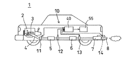
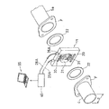
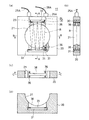
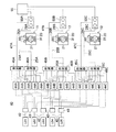
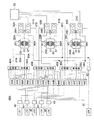
以下、本発明に係るガス分析装置を自動車の排ガス分析装置に用いた一実施形態を図面に基づき詳細に説明する。図1は、本実施形態に係る排ガス分析装置を自動車に搭載した要部構成図、図2は、図1の排ガス分析装置をエンジンベンチに搭載した状態の要部構成図、図3は、センサ部の要部の分解した状態の斜視図を含む排ガス分析装置の要部構成図、図4は、図3のセンサ部の詳細を示す一部を破断した正面図と、A−A線断面図、B−B線断面図およびC−C線要部断面図、図5は、レーザ発振・受光コントローラの要部構成および信号解析装置を含む排ガス分析装置の全体構成を示すブロック図である。 Hereinafter, an embodiment in which a gas analyzer according to the present invention is used in an automobile exhaust gas analyzer will be described in detail with reference to the drawings. FIG. 1 is a main part configuration diagram in which the exhaust gas analyzer according to the present embodiment is mounted on an automobile, FIG. 2 is a main part configuration diagram in a state in which the exhaust gas analyzer in FIG. 1 is mounted on an engine bench, and FIG. FIG. 4 is a front view showing a detail of the sensor unit in FIG. 3 and a cross-sectional view taken along line AA. FIG. 5 is a block diagram showing an overall configuration of an exhaust gas analyzer including a main configuration of a laser oscillation / light receiving controller and a signal analyzer.
図1〜5において、本実施形態の排ガス分析装置は、分析対象ガスとして、自動車1に設置されたエンジン(内燃機関)2から排出される排ガスを分析する装置である。また、図2に示すように、エンジンベンチ1Aに設置されたエンジン2の排ガスを分析する装置である。エンジン2の各気筒から排出される排ガスは、エキゾーストマニホルド3で合流され、排気管4を通して第1触媒装置5に導入され、さらに第2触媒装置6に導入され、そのあとマフラー7を通して排気パイプ8から大気中に放出される。排ガスが流れる流路(経路)を構成する排気経路は、エキゾーストマニホルド3、排気管4、第1触媒装置5、第2触媒装置6、マフラー7、排気パイプ8から構成され、エンジン2から排出された排ガスを2つの触媒装置5,6で浄化し、マフラー7により消音、減圧して大気中に放出する。なお、マフラーはメインマフラーとサブマフラーの2つを有するものでもよい。
1-5, the exhaust gas analyzer of this embodiment is an apparatus which analyzes the exhaust gas discharged | emitted from the engine (internal combustion engine) 2 installed in the
排気経路を構成する複数の部材は、フランジ部同士を対接させてボルト等で接続されている。例えば、第1、第2触媒装置5,6は大径の本体部の上流、下流側に排気パイプ部が連結され、これらの排気パイプ部の端部にフランジ部F,Fが溶接等により固着されている。また、マフラー7は大径の本体部の上流、下流側に排気パイプ部が連結され、これらの排気パイプ部の端部にフランジ部F,Fが固着されている。なお、末端の排気パイプ8はマフラー7に直接溶接等により固着されている。このように、排気経路を構成する複数の部材はフランジ部により接続され、排ガスが通過する断面形状が直径dの円形に形成されている。
The plurality of members constituting the exhaust path are connected by bolts or the like with the flange portions in contact with each other. For example, the first and second
本実施形態の排ガス分析装置10は、前記の排気経路の複数個所に設置された複数のセンサ部11〜14を備えて構成される。第1のセンサ部11は第1触媒装置5より上流側のエンジン側の排気管4との間に設置され、第2のセンサ部12は第1触媒装置5の下流側に設置され、第3のセンサ部13は第2触媒装置6の下流側に設置されている。そして、第4のセンサ部14はマフラー7の下流の排気パイプ8に設置されている。センサ部14は排気パイプの途中に設置されても、排気パイプの末端の開口部に挿入して設置するものでもよい。第1のセンサ部11の上流側の、エキゾーストマニホルド3で合流する前の1気筒毎の排気管にセンサ部を設置してもよい。
The
排気管4や第1触媒装置5、第2触媒装置6、マフラー7はフランジ部F,Fをボルトで締め付けることで連結されており、排気経路を構成する部材の間に設置されるセンサ部11,12,13は、フランジ部F,Fで挟まれた状態で設置されている。フランジ部F,Fは、排気経路を構成する部材の両端部に形成され、フランジ部同士の接合面は排気経路の中心線に対して直角に交差している。この結果、センサ部11〜13はフランジ部F,Fに挟まれて排気経路を横切るように設置される。第4のセンサ部14は排ガスが大気中に放出される直前の分析を行なうものであり、マフラー7から突出する排気パイプ8の中間部にフランジ部F,Fで挟んで設置してもよい。なお、センサ部の設置数は任意に設定すればよい。
The exhaust pipe 4, the
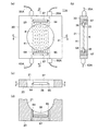
各センサ部11〜14は同一構成であり、1つのセンサ部11について図3,4を参照して説明する。センサ部11は矩形状の薄板材から形成されたセンサベース20を有し、このセンサベースは中心部に排気パイプ部の円形断面の内径dと同じ直径dの排ガス通過孔21が形成されており、排ガス通過孔内を排ガスが通過する。板状のセンサベース20の厚さはレーザ光の照射部と受光部とを固定できる範囲で、できるだけ薄いことが好ましい。具体的にはセンサベース20の厚さは、例えば5〜20mm程度が好適である。20mmを超えると排ガス流れに乱れが生じやすく、5mmより薄いと測定用のレーザ光の照射部や、排ガス中を透過したレーザ光の受光部の取付固定が煩雑となる。また、排気経路の任意の個所に必要に応じて容易に設置できる。なお、センサベース20の厚さは任意に設定できる。
Each sensor part 11-14 is the same structure, and demonstrates the one
このように、センサベース20に形成された排ガス通過孔21の形状は、排ガス流れを乱さないように排気パイプ部の内径と同じ直径の円形に形成され、しかもセンサベース20は薄く形成されている。このため、排気経路中にセンサ部11〜14を取付けても排ガス流れを乱すことがなく、圧力損失が少なく円滑に排気させることができる。排ガス通過孔21の形状は、例えば直径が30mmの場合、30±1〜2mm程度であれば排ガス流れの乱れが起きにくいので、このような範囲に設定されると好ましい。この程度の範囲が実質的に同じ断面形状として好ましい範囲である。センサベース20を構成する板材としては金属板材やセラミック製の板材を用いているが、材質については特に問わない。
Thus, the shape of the exhaust
センサベース20はフランジ部F,Fに挟まれた状態で固定され、フランジ部F,Fとセンサベース20との間にはガスケット22,22が挟まれた状態で図示していないボルト、ナット等により固定される。ガスケット22は石綿等で形成され、排気管の内径と同じ直径の排ガス通過孔が開けられている。この構成により、フランジ部F,Fの間にセンサベース20を挟んで排気経路を接続しても、排ガスが途中で漏れることはなく、排気経路の長さの増加も少ない。図3は、排気管4の下流端に溶接されたフランジ部Fと、触媒装置5の上流側の排気パイプ部5aの端部に溶接されたフランジ部Fとの間に、ガスケット22,22を挟んでセンサベース20が固定される構成を示している。
The
センサベース20には、板厚の中央を端面から排ガス通過孔に向けて貫通する2つのセンサ孔23,24が形成されている。センサ孔23,24は排ガス通過孔21に向けて開口しており、排ガスの流れる方向と直交して開口している。センサ部11はレーザ光を照射する照射部として光ファイバ25Aがセンサ孔23に固定され、光ファイバ25Aから照射され排ガス通過孔21内に存在する排ガス中を透過したレーザ光を受光する受光部として、ディテクタ26Aがセンサ孔24に固定されている。すなわち、センサ部11は、照射側の光ファイバ25Aから所定の入射角度で排気経路を横切るように照射されたレーザ光が、2つのミラー30,31で反射され、排ガス中を透過して減衰し、ディテクタ26Aで受光される構成となっている。
The
2つのミラー30,31は、図4に詳細に示すようにセンサベース20の中心部の円形の排ガス通過孔21外に、排ガス通過孔を挟持する対向位置において各々取り付けられており、ミラーの反射面が互いに平行となるようにして2枚配置され、測定用のレーザ光を反射させるように上下に設置固定される。すなわち、ミラー30,31は排ガス通過孔21外で、排ガス通過孔を挟んで対向して平行状態に配置されている。ミラー30,31は排ガス通過孔21の外周側に平行に形成された2つの挿入溝32,33内に着脱可能に固定されており、光ファイバ25Aから排ガス通過孔21に向けて照射されたレーザ光をディテクタ26Aに導き到達させる機能を有している。ミラー30,31は厚さが数mm程度の長方形状の基板状に形成され、基板の一方の面に金やプラチナの薄膜が反射面として形成され、その上に保護層として、MgF2やSiO2の薄膜が形成されている。なお、保護膜は形成しなくてもよい。
As shown in detail in FIG. 4, the two
また、ミラー30,31の表面に光触媒層を形成してもよい。光触媒層は、例えば二酸化チタン(TiO2)の薄膜が好ましい。光触媒層は塗布、あるいはコーティングによってミラーの表面に薄膜として形成されている。光触媒層が二酸化チタンの場合、この薄膜は紫外光等の光触媒用の光線を吸収して活性化し、表面に付着した汚れを浮上らせ、浮上った汚れは排ガス流れにより流されて排気経路から外部に排出されるように機能する。このように、ミラーの表面に光触媒層を形成すると、ミラーの表面を清浄化できて好ましい。
Further, a photocatalytic layer may be formed on the surfaces of the
センサベース20の排ガス通過孔21の外周に形成された挿入溝32,33は、ミラー30,31が緩く挿入できる程度の大きさに設定されている。挿入溝32,33はセンサベース20を貫通して両面側に開口しても、あるいは片面側に開口して他面側が閉塞している形状でもよい。ミラー30,31は挿入溝32,33内で取付ビス36によりスペーサ37を介して固定されている。ミラーが熱ショック等により破損した場合は、取付ビス36を緩めることで取り外して新しいミラーを固定することができる。また、ミラーが汚れたときに、センサベース20から取り外して清掃することもできる。
The
ミラー30,31は取付ビス36によりスペーサ37を介して固定されているため、エンジンの振動や排気管等の排気経路の振動でミラーが振動することを防止している。ミラーと取付ビスとの熱膨張の差を吸収するためスペーサ37が挟まれており、緩衝材として機能している。スペーサとしては耐環境性に優れ、弾性変形するものが好ましい。例えば、雲母系やカーボン系、銅等の板材が好ましい。このように、スペーサを介して取付ビスで固定することにより、800℃程度の高温状態でも振動することなく、安定して固定することができる。
Since the
ミラー30,31は石英、若しくはサファイア、セラミック等の母材の表面に反射材をコーティングして作製する。コーティング材としては、金や酸化チタン等のレーザ波長に合った反射率の高いものを選択することが好ましい。また、反射材を保護するコーティングとしてSiO2等の透明で耐熱性に優れ、耐環境性に優れたものを最上面に形成することが好ましい。耐熱性に優れ、反射率の高いミラーを用いることで精度良い測定が可能となる。また、反射材として酸化チタンを用いるときは、酸化チタンが単独で耐環境性に優れ、光触媒として汚れ防止に有効であるため保護膜を形成する必要がなく、そのままの状態で測定することが好ましい。
The
排ガス通過孔21の内周面とミラーを固定する挿入溝32,33との間には、測定用のレーザ光がミラーに到達できるように貫通路が形成されている。貫通路としては貫通するスリットや、貫通する通過孔等が形成される。本実施形態では、排気経路に直交する方向に幅が数mm程度のスリット38,38が排ガス通過孔21の内周面から挿入溝32,33まで連通させて形成され、スリットは排ガス通過孔21の内周面とミラー30,31とを貫通している。この構成により、測定用の赤外レーザ光Rが照射部である光ファイバ25からセンサ孔23を通して排ガス通過孔21内に照射されると、下方のスリット38を通して下方のミラー31に到達し、下方のミラーで上方に反射され、次いで上方のスリット38を通して上方のミラー30に到達し、上方のミラーで下方に反射され、上下で反射を繰返したあと上方に固定されたディテクタ26Aに受光される構成となっている。
A through path is formed between the inner peripheral surface of the exhaust
光ファイバ25Aおよびディテクタ26Aはレーザ発振・受光コントローラ40に接続され、レーザ発振・受光コントローラ40から出射される赤外レーザ光が光ファイバ25Aを通してセンサベース20の排ガス通過孔21内に照射され、排ガス中を透過した赤外レーザ光が受光側のディテクタ26Aで受光され、信号線28Aを介してレーザ発振・受光コントローラ40に入力される構成となっている。光ファイバ25Aから照射された発光強度と、排ガス中を透過してディテクタ26Aで受光された受光強度等が、分析装置であるパーソナルコンピュータ55に供給される。このように、排ガス分析装置10は、複数のセンサ部11〜14と、レーザ発振・受光コントローラ40と、パーソナルコンピュータ55とを備えて構成される。
The
ここで、レーザ発振・受光コントローラ40について、図5を参照して説明する。レーザ発振・受光コントローラ40は、複数の波長の赤外レーザ光を照射する照射装置として、複数のレーザダイオードLD1〜LD5に、図示していないファンクションジェネレータ等の信号発生器から複数の周波数の信号を供給し、レーザダイオードLD1〜LD5は各周波数に対応してそれぞれ複数の波長の赤外レーザ光を照射する。レーザ発振・受光コントローラ40の信号発生器から出力される複数の周波数の信号がレーザダイオードLD1〜LD5に供給されて発光し、例えばLD1は波長が1300〜1330nm程度、LD2は1330〜1360nmというように、検出しようとする成分ガスのピーク波長が存在する波長帯が連続するような波長帯の赤外レーザ光を発生させるように設定されている。
Here, the laser oscillation /
排ガス中を透過させる赤外レーザ光の波長は、検出する排ガスの成分に合わせて設定され、一酸化炭素(CO)、二酸化炭素(CO2)、アンモニア(NH3)、メタン(CH4)、水(H2O)を検出する場合は、5つの波長の赤外レーザ光を使用する。例えば、アンモニアを検出するのに適した波長は1530nmであり、一酸化炭素を検出するのに適した波長は1560nmであり、二酸化炭素を検出するのに適した波長は1570nmである。また、メタンを検出するのに適した波長は1680nmであり、水を検出するのに適した波長は1350nmである。さらに、他の排ガスの成分の濃度を検出する場合は、排ガス成分の数に合わせて異なる波長の赤外レーザ光を使用する。なお、ガス濃度の検出は、同じ成分でも異なる波長である場合があり、異なる波長の中から選択して用いるようにしてもよい。 The wavelength of the infrared laser beam that passes through the exhaust gas is set in accordance with the component of the exhaust gas to be detected. Carbon monoxide (CO), carbon dioxide (CO 2 ), ammonia (NH 3 ), methane (CH 4 ), When detecting water (H 2 O), infrared laser beams having five wavelengths are used. For example, the wavelength suitable for detecting ammonia is 1530 nm, the wavelength suitable for detecting carbon monoxide is 1560 nm, and the wavelength suitable for detecting carbon dioxide is 1570 nm. The wavelength suitable for detecting methane is 1680 nm, and the wavelength suitable for detecting water is 1350 nm. Furthermore, when detecting the concentration of other exhaust gas components, infrared laser beams having different wavelengths are used in accordance with the number of exhaust gas components. Note that the gas concentration may be detected at different wavelengths even for the same component, and may be selected from different wavelengths.
各レーザダイオードLD1〜LD5から照射された赤外レーザ光は光ファイバ42…により分波器43…に導光され、センサ部の数に合わせて分波器43…により分波される。図5では3つのセンサ部11〜13に合わせて各レーザダイオードLD1〜LD5から照射されたレーザ光は3つに分波される。そして分波器43…で分波されたレーザ光は、分波器44A…、44B…、44C…により信号光と測定光に分けられる。分波器44A…はセンサ部11用であり、分波器44B…はセンサ部12用、分波器44C…はセンサ部13用である。センサ部11用の5つの分波器44A…で分けられた信号光は光ファイバを通して合波器45Aで合波され、合波された複数の波長帯の信号光は光ファイバ47Aを通して後述する差分型光検出器50Aに導光される。一方、5つの分波器44A…で分けられた測定光は光ファイバを通して合波器46Aで合波され、光ファイバ25Aによりセンサ部11の照射部に導光される。
The infrared laser light emitted from each of the laser diodes LD1 to LD5 is guided to the
また、分波器43…で分波された赤外レーザ光は、センサ部12用の5つの分波器44B…により信号光と測定光に分けられ、信号光は合波器45Bで複数の波長帯を合波した信号光となり、光ファイバ47Bを通して差分型光検出器50Bに導光される。5つの分波器44B…により分けられた測定光は合波器46Bで合波され、光ファイバ25Bによりセンサ部12の照射部に導光される。さらに、分波器43…で分波された赤外レーザ光は、センサ部13用の5つの分波器44C…により信号光と測定光に分けられ、信号光は合波器45Cで複数の波長帯の信号光となり、光ファイバ47Cを通して差分型光検出器50Cに導光される。5つの分波器44C…により分けられた測定光は合波器46Cで合波され、光ファイバ25Cによりセンサ部13の照射部に導光される。
Further, the infrared laser light demultiplexed by the
図5では、3つのセンサ部11〜13を示しているが、さらに多くのセンサ部14…を設置する場合は、分波器43でさらに多くのレーザ光に分波し、分波したレーザ光をさらに多くの分波器44…で測定光と信号光に分波し、信号用のレーザ光を合波器45…で合波してから差分型光検出器50…に導光すると共に、測定用のレーザ光を合波器46…で合波してから、さらに多くのセンサ部14…に導光する。
In FIG. 5, three
本実施形態の排ガス分析装置10は、測定用の赤外レーザ光をミラー30,31で反射させ排ガス中の透過距離を大きくするように構成されており、ミラー30,31で繰り返し反射された測定用のレーザ光がディテクタで受光される構成となっている。センサ部11〜13の受光部に接続された受光側のディテクタ26A,26B,26Cはレーザ発振・受光コントローラ40の差分型光検出器50A,50B,50Cに信号線28A,28B,28Cを介して接続される。また、合波器45A,45B,45Cで合波された信号光は光ファイバ47A,47B,47Cを通して差分型光検出器50A,50B,50Cに導光される。
The
3つの差分型光検出器50A,50B,50Cでは、排ガス中を透過して減衰した透過レーザ光と、排ガス中を透過していない信号レーザ光との差を取る構成となっている。信号レーザ光はフォトダイオード等に入力され、電気信号に変換される。差分型光検出器で算出された信号光と測定光の差分に相当する電気信号は、例えば図示していないプリアンプで増幅され、A/D変換器を介して信号解析装置であるパーソナルコンピュータ55に入力される。パーソナルコンピュータ55では、入力された信号から排ガスの成分の濃度や、排ガスの温度を算出して排ガスを分析する。
The three
本発明の排ガス分析装置10は、例えば赤外レーザ光を排ガス中に透過させ、入射光の強度と排ガス中を透過したあとの透過光の強度に基づいて排ガスの成分の濃度を算出し、排ガスを分析するものである。すなわち、排ガスの成分の濃度Cは、以下の数式(1)から算出される。
C=−ln(I/I0)/kL…(1)
The
C = −ln (I / I 0 ) / kL (1)
この数式(1)において、Iは透過光強度、I0は入射光強度、kは吸収率、Lは透過距離である。したがって、信号光である入射光強度(I0)に対する透過光強度(I)の比、シグナル強度(I/I0)に基づいて排ガスの成分の濃度Cは算出される。透過光強度Iは、ディテクタ26A,26B,26Cを通して出力され、入射光強度I0は、光ファイバ47A,47B,47Cを通して差分型光検出器50A,50B,50C内のフォトダイオード等の光電変換器から出力される。本実施形態では入射光強度I0として、排ガス中を透過しない信号光強度を用いている。
In Equation (1), I is the transmitted light intensity, I 0 is the incident light intensity, k is the absorptance, and L is the transmission distance. Therefore, the concentration C of the exhaust gas component is calculated based on the ratio of the transmitted light intensity (I) to the incident light intensity (I 0 ), which is signal light, and the signal intensity (I / I 0 ). Transmitted light intensity I, the
前記の如く構成された本実施形態の排ガス分析装置10の動作について以下に説明する。排ガスの成分の濃度を測定するときは、レーザ発振・受光コントローラ40の信号発生器を作動させて各レーザダイオードLD1〜LD5に信号を供給して各レーザダイオードLD1〜LD5から所定の波長の赤外レーザ光を発光させる。各レーザダイオードLD1〜LD5から発光された赤外レーザ光は、光ファイバ42…を通して分波器43…に至り、ここでセンサ部の数に合わせて分波される。
The operation of the
このあと、分波された赤外レーザ光は分波器44A…,44B…,44C…で測定光と信号光に分波される。1つのセンサ部11について詳細に説明すると、5つの分波器44Aで分波された信号光は合波器45Aで合波されて信号用レーザ光となり、差分型光検出器50Aに導光される。また、5つの分波器44Aで分波された測定光は合波器46Aで合波されて測定用レーザ光となり、センサ部11の照射部に光ファイバ25Aを通して導光される。他のセンサ部12,13についても、同様に分波器43…で分波されたあと、分波器44B…,44C…で信号光と測定光に分波され、合波器45B,45Cで合波されて、信号光は差分型光検出器50B,50Cに導光され、合波器46B,46Cで合波されて、測定光がセンサ部12,13に導光される。
Thereafter, the demultiplexed infrared laser light is demultiplexed into measurement light and signal light by
そして、センサ部11〜13の光ファイバ25A,25B,25Cから照射された測定用の赤外レーザ光は、センサ孔23を通して排ガスが通過している排ガス通過孔21内に照射される。赤外レーザ光は排気経路である排ガス通過孔21内を横切り、スリット38を通して下方のミラー31に到達しこのミラーで上方に反射され、ついで上方のスリット38を通して上方のミラー30で下方に反射され、反射を繰返すことで排ガス中の透過距離が大きくなり、最後にセンサ孔24を通してディテクタ26A,26B,26Cで受光される。すなわち、測定用の赤外レーザ光は排ガス中を透過して減衰され、減衰された透過光が受光部であるディテクタで受光され、透過光(測定光)の光強度が測定される。
The infrared laser light for measurement irradiated from the optical fibers 25 </ b> A, 25 </ b> B, and 25 </ b> C of the
このように、測定用の赤外レーザ光は排気経路を構成するセンサ部の排ガス通過孔21内の、排気経路と直交する面内を横切って受光されるため、直交する1断面における排ガスの成分の濃度や温度をスポット的に測定することができる。すなわち、排気経路に沿った、ある長さの範囲の排ガスの成分の濃度や温度を測定するのでなく、排気経路を横切る所定の1面を基準とした排ガスの成分の濃度や温度を測定することができるので、スポット的な測定が可能となる。
In this way, the measurement infrared laser light is received across the plane perpendicular to the exhaust path in the exhaust
排ガス中を通り減衰して受光部に到達した測定用の赤外レーザ光はディテクタ26A,26B,26Cで電気信号として出力され、信号線28A,28B,28Cを介して差分型光検出器50A,50B,50Cに供給される。一方、信号用レーザ光は差分型光検出器50A,50B,50Cに供給され、差分型光検出器では、複数の波長成分毎に透過光(測定光)と信号光の差を取り、透過光のうちの特定ガス成分のピーク波長を検出する。このようにして、差分型光検出器からの出力が信号解析装置であるパーソナルコンピュータ55に入力される。パーソナルコンピュータ55は、入力された複数の周波数帯ごとのピーク波長に基づいて、排ガスの成分の濃度測定や温度測定を実施して分析する。
The measurement infrared laser light that has attenuated through the exhaust gas and reached the light receiving section is output as an electrical signal by the
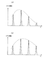
気体は、それぞれ固有の吸収波長帯を持っており、その吸収波長帯には、例えば図6に示すように、多くの吸収線が存在している。図6aは低温のときのシグナル強度(=分子数割合)を示しており、図6bは高温のときのシグナル強度を示している。このように、シグナル強度は温度に依存して変化するため、シグナル強度比を測定することにより、測定時の排ガスの温度を算出することができる。 Each gas has its own absorption wavelength band, and many absorption lines exist in the absorption wavelength band, for example, as shown in FIG. FIG. 6a shows the signal intensity at the low temperature (= number of molecules), and FIG. 6b shows the signal intensity at the high temperature. Thus, since the signal intensity changes depending on the temperature, the temperature of the exhaust gas at the time of measurement can be calculated by measuring the signal intensity ratio.
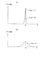
そして、図7に示すように、吸収線のうちの1本、例えば波長λ1に対してレーザ光の発振波長を掃引することによって吸収を測定する。この波形と信号レーザ光の波形との比をとることによって、スペクトルプロファイルを測定する。また、温度測定は、前記のスペクトルプロファイルを異なる2つの吸収線λ1、λ2について測定し、それらの面積比A1/A2(またはピークの高さの比P1/P2)をとることにより求めることができる。従来の波長変調法では、図7aに示すように、吸収スペクトルピークの先端の曲率により排ガスの成分の濃度を算出していたが、本発明では、図7bに示すように、吸収スペクトルの面積により排ガスの成分の濃度を算出するため、圧力の影響を受けにくい排ガスの成分の濃度の算出が可能となる。 Then, as shown in FIG. 7, the absorption is measured by sweeping the oscillation wavelength of the laser light with respect to one of the absorption lines, for example, the wavelength λ1. The spectrum profile is measured by taking the ratio between this waveform and the waveform of the signal laser beam. Further, the temperature measurement can be obtained by measuring the spectrum profile for two different absorption lines λ1 and λ2 and taking the area ratio A1 / A2 (or the peak height ratio P1 / P2). . In the conventional wavelength modulation method, as shown in FIG. 7a, the concentration of the exhaust gas component is calculated based on the curvature of the tip of the absorption spectrum peak. However, in the present invention, as shown in FIG. Since the concentration of the exhaust gas component is calculated, it is possible to calculate the concentration of the exhaust gas component that is not easily affected by pressure.
排ガス中に含まれる成分の濃度の測定や、排ガスの温度の測定は、測定用の赤外レーザ光をセンサ部11〜14の照射部である光ファイバからセンサ孔23を通して排ガス通過孔21内に照射し、レーザ光は下方のスリット38を通して下方のミラー31に到達し、ミラーで上方に向けて反射され、下方のスリット38および上方のスリット38を通して上方のミラー30に到達して下方に反射される。このように、測定用の赤外レーザ光は、センサベースの排ガス通過孔21の上下に形成されたスリット38,38を通して上下のミラー30,31で反射を繰り返し、本実施形態では7回の反射を繰返したあと、受光部であるディテクタ26Aで受光され、透過光強度として測定される。
Measurement of the concentration of components contained in the exhaust gas and measurement of the temperature of the exhaust gas are carried out by passing infrared laser light for measurement from the optical fiber as the irradiation part of the
この測定に際し、センサ部のセンサベース20には、排気経路の断面形状と同じ直径の円形の排ガス通過孔21が形成され、しかもセンサベース20の厚さが薄く形成されていると共に、レーザ光が通過するセンサ孔23,24やスリット38,38が小さく形成されているため、排ガス流れを乱すことがなく排ガスが安定して流通するため、排気効率の低下を防止できる。しかも、排ガス流れを乱すことなく、排ガス中を透過させるレーザ光を反射させて排ガス中の透過距離を大きくして受光し、減衰量を大きくすることができるため、精度の高い測定が可能となる。なお、排ガス通過孔の断面形状は、排ガスの流れを乱さない範囲でほぼ等しく形成してもよい。
In this measurement, a circular exhaust
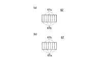
本発明の他の実施形態を図8〜10に基づき詳細に説明する。図8は本発明に係る排ガス分析装置で使用するセンサ部の他の実施形態の正面図、D−D線断面図、E−E線断面図、F−F線要部断面図、図9はミラーの平面図と底面図、図10は図8,9に示すセンサ部を使用するレーザ発振・受光コントローラの要部構成および信号解析装置を含む排ガス分析装置の全体構成を示すブロック図である。 Another embodiment of the present invention will be described in detail with reference to FIGS. FIG. 8 is a front view of another embodiment of the sensor unit used in the exhaust gas analyzer according to the present invention, a sectional view taken along the line DD, a sectional view taken along the line EE, a sectional view taken along the line FF, and FIG. FIG. 10 is a block diagram showing the main configuration of a laser oscillation / light-receiving controller using the sensor unit shown in FIGS. 8 and 9 and the overall configuration of the exhaust gas analyzer including the signal analyzer.
なお、この実施形態は前記した実施形態に対し、排ガス分析装置は複数のレーザ光発生手段として、赤外レーザ光発生手段LD1〜LD5と可視レーザ光発生手段LD6とを備えており、それぞれのレーザ光に対応して反射部材であるミラーは複数の反射面を備えることを特徴としている。すなわち、赤外レーザ光に対して反射率の高い反射面と、可視レーザ光に対して反射率の高い反射面の両方の反射面を形成している。そして、他の実質的に同等の構成については同じ符号を付して詳細な説明は省略する。 Note that this embodiment is different from the above-described embodiment in that the exhaust gas analyzer includes infrared laser light generating means LD1 to LD5 and visible laser light generating means LD6 as a plurality of laser light generating means. A mirror that is a reflecting member corresponding to light is characterized by including a plurality of reflecting surfaces. In other words, both the reflective surface having a high reflectance with respect to the infrared laser light and the reflective surface having a high reflectance with respect to the visible laser light are formed. Other substantially equivalent configurations are denoted by the same reference numerals, and detailed description thereof is omitted.
図8に示されるセンサ部11Aは、前記の実施形態で示すセンサ部11〜14と同様に、車両の排気経路中に設置できるように構成されている。このセンサ部11Aは、基本的には前記実施形態のセンサ部11と赤外レーザ光が照射され受光される構成は同じであり、この構成と共に可視レーザ光を照射して受光する構成が付加されている。すなわち、センサベース20の上方の左方に赤外レーザ光の照射部として光ファイバ25Aが固定され、右方に赤外レーザ光の受光部としてディテクタ26Aが固定されている。
The
図10に示される可視レーザ光発生手段LD6には、光ファイバ61が接続され、可視レーザ光は分波器62に導光される。分波器62では、3つのセンサ部に対応して可視レーザ光を信号光と測定光の2つに分波し、光ファイバ63A,63Bを介して3つのセンサ部に導光している。各光ファイバ63Aは、センサベース20の左下方に接続され、可視レーザ光を照射する照射部として機能する。この実施形態では、測定用レーザ光として赤外レーザ光と可視レーザ光を使用することにより、前記の実施形態より多種の排ガス成分の濃度測定が可能となる。例えば、排ガス中に含まれる酸素の濃度を測定する場合は、波長が760nm程度の帯域を用いることで容易に測定することができる。
An
センサベース20には可視レーザ光R1用のセンサ孔64,65が形成され、これらのセンサ孔は、図8bに示されるように、赤外レーザ光R用のセンサ孔23,24と中心面に対してずらして形成されている。センサ孔64に光ファイバ63Aが照射部として固定され、センサ孔65に可視レーザ光の受光部としてディテクタ66A(66B,66C)が固定されている。この構成により、赤外レーザ光Rと可視レーザ光R1とは別々の面上の光路で反射が繰り返されて受光され、赤外レーザ光の光路と可視レーザ光の光路とが交差しないように構成されている。
Sensor holes 64 and 65 for the visible laser beam R1 are formed in the
反射部材であるミラー67,67は赤外レーザ光発生手段であるLD1〜LD5から発生される赤外レーザ光Rと、可視レーザ光発生手段であるLD6から発生される可視レーザ光R1に対応して、反射率の高い反射面を備えている。ミラー67,67は赤外レーザ光Rを反射させスリット38を通してディテクタ26Aに到達させるものであると共に、可視レーザ光R1を反射させスリット38を通してディテクタ66Aに到達させるものである。なお、ミラーの固定手段は図8では省略しているが、前記の実施形態と同様に挿入溝内にスペーサを挟んで取付ビス等で固定される。
The
上方のミラー67は、底面形状を示す図9aにおいて、ミラーの表面に赤外レーザ光の反射率の高い反射面としてタンタル系の反射面67aと、可視レーザ光の反射率の高い反射面として金の薄膜を形成した反射面67bとが交互に、所定の幅で形成されている。また、下方のミラー67は、平面形状を示す図9bにおいて、ミラーの表面には、タンタル系の反射面67aと、金の反射面67bとが交互に、所定の幅で形成されている。すなわち、上方のミラー67の反射面と、下方のミラーの反射面とは、反射面67aと反射面67bとの配置が反対となっている。このように、反射面67aと反射面67bとを交互に配置させることにより、光路長を長くしてもミラーの小型化を図ることができる。
The
本実施形態では、図10に示されるレーザ発振・受光コントローラ40Aにおいて、センサ部11A〜13Aのセンサベース20には上面に赤外レーザ光の発生手段LD1〜LD5からの光ファイバ25A〜25Cが接続され、光ファイバから照射された赤外レーザ光が排ガス中を透過して受光される受光部としてディテクタ26A〜26Cが固定されている。また、センサベース20の下面には可視レーザ光が供給されている。すなわち、可視レーザ光の発生手段であるレーザダイオードLD6から光ファイバ61が接続され、分波器62で信号光と測定光に分波される。そして、測定光は光ファイバ63Aで3つのセンサ部に供給され、各センサ部の照射部から照射された可視レーザ光が排ガス中を透過して受光される受光部としてディテクタ66A〜66Cが固定されている。信号光は光ファイバ63Bで3つの差分型光検出器51A〜51Cに供給され、3つのディテクタから供給される光強度との差が検出される。
In this embodiment, in the laser oscillation /
1つのセンサ部11Aについてより詳細に説明すると、上方の光ファイバ25Aから照射された赤外レーザ光は下方のミラー67の赤外光用の反射面67a、上方のミラー67の赤外光用の反射面67aで高い反射率で反射され、さらに複数回反射が繰り返されて上方のディテクタ26Aで受光される。また、下方の光ファイバ63Aから照射された可視レーザ光は上方のミラー67の可視光用の反射面67b、下方のミラー67の可視光用の反射面67bで高い反射率で反射され、さらに複数回反射が繰り返されて下方のディテクタ66Aで受光される。このように、赤外レーザ光Rと可視レーザ光R1とは別々の光路で反射が繰り返されて受光されるため、赤外レーザ光と可視レーザ光とは交差しないでディテクタに到達し、相互に干渉されることがない。
In more detail about one
この実施形態では、赤外レーザ光の波長帯に適した排ガスの成分の濃度を赤外レーザ光で測定し、可視レーザ光の波長帯に適した排ガスの成分の濃度を可視レーザ光で測定するため、多数の種類の排ガスの成分の濃度を効率良く、高精度で測定することができる。しかも、排ガスの成分に合わせて赤外レーザ光と可視レーザ光とを使用するため、排ガスの成分に最適な波長を用いることができるため、迅速な測定が可能となる。また、ミラー67は赤外レーザ光用の反射面67aと、可視レーザ光用の反射面67bとを交互に形成するため、作製が容易となる。なお、反射面の形成は、先ず一方の反射面を全面に形成し、次いで他方の反射面を間隔を空けて形成してもよい。
In this embodiment, the concentration of exhaust gas components suitable for the wavelength band of infrared laser light is measured with infrared laser light, and the concentration of exhaust gas components suitable for the wavelength band of visible laser light is measured with visible laser light. Therefore, the concentration of the components of many types of exhaust gas can be measured efficiently and with high accuracy. In addition, since infrared laser light and visible laser light are used in accordance with the components of the exhaust gas, the optimum wavelength can be used for the components of the exhaust gas, so that rapid measurement is possible. Further, since the
以上、本発明の実施形態について詳述したが、本発明は、前記の実施形態に限定されるものではなく、特許請求の範囲に記載された本発明の精神を逸脱しない範囲で、種々の設計変更を行なうことができるものである。例えば、センサベースのレーザ光が通過する貫通路としてスリットの例を示したが、断面が円形の貫通孔を形成してレーザ光を通過させるように構成してもよい。また、直径が徐々に変化するテーパ孔で貫通路を形成してもよい。 Although the embodiments of the present invention have been described in detail above, the present invention is not limited to the above-described embodiments, and various designs can be made without departing from the spirit of the present invention described in the claims. It can be changed. For example, although the example of the slit is shown as the through path through which the sensor-based laser beam passes, the laser beam may be configured to pass through a through hole having a circular cross section. Further, the through path may be formed by a tapered hole whose diameter gradually changes.
複数のレーザ光発生手段として、赤外レーザ光発生手段と可視レーザ光発生手段の2つの発生手段を備える例を示したが、さらに、例えば紫外レーザ光発生手段を備えるように構成してもよいのは勿論である。そして、さらに多数のレーザ光発生手段をセンサ部に備え、その発生手段に対応して複数の受光手段を備えるように構成してもよい。 Although an example in which two laser light generating means and two visible laser light generating means are provided as a plurality of laser light generating means has been shown, for example, an ultraviolet laser light generating means may be provided. Of course. Further, a larger number of laser light generating means may be provided in the sensor unit, and a plurality of light receiving means may be provided corresponding to the generating means.
センサ部のセンサベースに照射部として光ファイバを、受光部としてディテクタを備える例を示したが、センサベースに直接レーザダイオード等の照射部を備えてもよく、フォトダイオード等のディテクタの代わりに受光用の光ファイバを装着する構成としてもよい。また、光ファイバの照射部にコリメータレンズを設け、コリメータレンズを通して排ガス通過孔内にレーザ光を照射するようにしてもよい。 Although the sensor base of the sensor unit is provided with an optical fiber as an irradiator and a detector as a light receiver, the sensor base may be provided with an irradiator such as a laser diode directly, and receives light instead of a detector such as a photodiode. It is good also as a structure which mounts the optical fiber for use. Moreover, a collimator lens may be provided in the irradiation part of the optical fiber, and laser light may be irradiated into the exhaust gas passage hole through the collimator lens.
本発明の活用例として、このガス分析装置を用いてボイラー等の燃焼装置の排ガス分析を行なうことができ、自動車の排ガス分析の他に船舶や発電機等で使用する内燃機関の排ガス分析の用途にも適用できる。また、ガソリンエンジンの排ガス分析の他にディーゼルエンジンの排ガス分析を行なうことができ、さらに他の内燃機関の排ガス分析の用途にも適用できる。 As an application example of the present invention, this gas analyzer can be used for exhaust gas analysis of combustion devices such as boilers, and in addition to automobile exhaust gas analysis, it is used for exhaust gas analysis of internal combustion engines used in ships, generators, etc. It can also be applied to. In addition to the exhaust gas analysis of a gasoline engine, exhaust gas analysis of a diesel engine can be performed, and further, it can be applied to the use of exhaust gas analysis of other internal combustion engines.
1:自動車、1A:エンジンベンチ、2:エンジン(内燃機関)、3:エキゾーストマニホルド(排気経路)、4:排気管(排気経路)、5:第1触媒装置(排気経路)、6:第2触媒装置(排気経路)、7:マフラー(排気経路)、8:排気パイプ(排気経路)、10:排ガス分析装置(ガス分析装置)、11〜14:センサ部、20:センサベース、21:排ガス通過孔、25A〜25C,63A:光ファイバ(レーザ光照射部)、26A〜26C,66A:ディテクタ(レーザ光受光部)、30,31:ミラー、38:スリット(貫通路)、40:レーザ発振・受光コントローラ、43:分波器、44A〜44C:分波器、45A〜45C,46A〜46C:合波器、50A〜50C,51A〜51C:差分型光検出器、55:パーソナルコンピュータ(信号解析装置)、67:ミラー、67a:反射面(赤外レーザ光用反射面)、67b:反射面(可視レーザ光用反射面)、LD1〜LD5:赤外レーザ光発生手段、LD6:可視レーザ光発生手段
1: automobile, 1A: engine bench, 2: engine (internal combustion engine), 3: exhaust manifold (exhaust path), 4: exhaust pipe (exhaust path), 5: first catalyst device (exhaust path), 6: second Catalyst device (exhaust path), 7: Muffler (exhaust path), 8: Exhaust pipe (exhaust path), 10: Exhaust gas analyzer (gas analyzer), 11-14: Sensor unit, 20: Sensor base, 21: Exhaust gas Passing hole, 25A to 25C, 63A: optical fiber (laser light irradiation part), 26A to 26C, 66A: detector (laser light receiving part), 30, 31: mirror, 38: slit (through path), 40: laser oscillation Light receiving controller, 43: demultiplexer, 44A-44C: demultiplexer, 45A-45C, 46A-46C: multiplexer, 50A-50C, 51A-51C: differential photodetector, 55: personal 67: mirror, 67a: reflecting surface (reflecting surface for infrared laser light), 67b: reflecting surface (reflecting surface for visible laser light), LD1 to LD5: infrared laser light generating means, LD6: Visible laser light generating means
Claims (8)
該ガス分析装置は、前記ガスが流れる経路に固定されるセンサ部を備えており、
該センサ部は、
前記ガスにレーザ光を照射するためのレーザ光照射部と、
ガス中を透過したレーザ光を受光するための受光部と、
ガスが流れる経路の断面形状と実質的に同じ断面形状であるガス通過孔と、
該ガス通過孔外に配置されレーザ光を反射させる反射部材と、
該反射部材と前記ガス通過孔とを結ぶ貫通路と、を少なくとも備えており、
前記センサ部は、前記レーザ光照射部から照射されたレーザ光が、ガス通過孔を通過するガス中を透過し、前記貫通路を通して前記反射部材に到達し、該反射部材で反射され前記貫通路を通してガス中をさらに透過し、前記受光部に導かれるように構成されていることを特徴とするガス分析装置。 A gas analyzer that irradiates a gas to be analyzed with a laser beam and measures and analyzes the component concentration and temperature of the gas based on the laser beam transmitted through the gas,
The gas analyzer includes a sensor unit fixed to a path through which the gas flows,
The sensor unit is
A laser beam irradiation unit for irradiating the gas with a laser beam;
A light receiving portion for receiving laser light transmitted through the gas;
A gas passage hole having substantially the same cross-sectional shape as the cross-sectional shape of the path through which the gas flows;
A reflecting member disposed outside the gas passage hole and reflecting the laser beam;
A through path connecting the reflecting member and the gas passage hole, at least,
The sensor unit transmits the laser beam emitted from the laser beam irradiation unit through the gas passing through the gas passage hole, reaches the reflection member through the through path, is reflected by the reflection member, and is reflected through the through path. The gas analyzer is configured to further pass through the gas through the gas and be guided to the light receiving unit.
Priority Applications (1)
| Application Number | Priority Date | Filing Date | Title |
|---|---|---|---|
| JP2005226767A JP4781039B2 (en) | 2005-08-04 | 2005-08-04 | Gas analyzer |
Applications Claiming Priority (1)
| Application Number | Priority Date | Filing Date | Title |
|---|---|---|---|
| JP2005226767A JP4781039B2 (en) | 2005-08-04 | 2005-08-04 | Gas analyzer |
Publications (2)
| Publication Number | Publication Date |
|---|---|
| JP2007040887A true JP2007040887A (en) | 2007-02-15 |
| JP4781039B2 JP4781039B2 (en) | 2011-09-28 |
Family
ID=37799001
Family Applications (1)
| Application Number | Title | Priority Date | Filing Date |
|---|---|---|---|
| JP2005226767A Expired - Fee Related JP4781039B2 (en) | 2005-08-04 | 2005-08-04 | Gas analyzer |
Country Status (1)
| Country | Link |
|---|---|
| JP (1) | JP4781039B2 (en) |
Cited By (10)
| Publication number | Priority date | Publication date | Assignee | Title |
|---|---|---|---|---|
| JP2010243172A (en) * | 2009-04-01 | 2010-10-28 | Riken Keiki Co Ltd | Multi-layer multipass cell and gas measuring instrument |
| JP2010243269A (en) * | 2009-04-03 | 2010-10-28 | Riken Keiki Co Ltd | Multipass cell and gas meter |
| JP2010243270A (en) * | 2009-04-03 | 2010-10-28 | Riken Keiki Co Ltd | Combined multipass cell and gas meter |
| JP2010536042A (en) * | 2007-08-15 | 2010-11-25 | ウーハン・チャンホン・インスツルメンツ・カンパニー・リミテッド | Long-path atmospheric monitoring and measuring device |
| JP2010538248A (en) * | 2007-08-31 | 2010-12-09 | エスピースリーエイチ | A device for centralized measurement and data management of liquid and gas flows required for the operation of a combustion engine |
| JP2012026918A (en) * | 2010-07-26 | 2012-02-09 | Fuji Electric Co Ltd | Multicomponent laser gas analyzer |
| JP2014102140A (en) * | 2012-11-20 | 2014-06-05 | Fuji Electric Co Ltd | Laser type oxygen gas analyzer |
| JP2015155848A (en) * | 2014-02-20 | 2015-08-27 | 株式会社四国総合研究所 | optical sensor chip |
| WO2018216122A1 (en) * | 2017-05-23 | 2018-11-29 | 株式会社島津製作所 | Heat-resistant reflecting mirror, gas concentration monitor and method for producing heat-resistant reflecting mirror |
| JP2020016472A (en) * | 2018-07-23 | 2020-01-30 | 東京都下水道サービス株式会社 | Gas concentration measuring device |
Families Citing this family (1)
| Publication number | Priority date | Publication date | Assignee | Title |
|---|---|---|---|---|
| KR102421450B1 (en) * | 2020-09-24 | 2022-07-18 | 성균관대학교산학협력단 | Gas temperature field measuring device |
Citations (8)
| Publication number | Priority date | Publication date | Assignee | Title |
|---|---|---|---|---|
| JPS5378992U (en) * | 1976-12-02 | 1978-06-30 | ||
| JPS5476784U (en) * | 1977-11-10 | 1979-05-31 | ||
| JPS56117344U (en) * | 1980-02-08 | 1981-09-08 | ||
| JPS5818150A (en) * | 1981-07-24 | 1983-02-02 | Hochiki Corp | Light depreciation type smoke detector |
| JPH0214056U (en) * | 1988-07-11 | 1990-01-29 | ||
| JPH09269293A (en) * | 1996-04-01 | 1997-10-14 | Nisshin Koki Kk | Particulate detector |
| JP2000074830A (en) * | 1998-08-28 | 2000-03-14 | Horiba Ltd | High-speed measuring method and measuring system for temperature, concentration and chemical species by use of semiconductor laser spectroscopy |
| JP2004053405A (en) * | 2002-07-19 | 2004-02-19 | Horiba Ltd | Inline gas analyzer |
-
2005
- 2005-08-04 JP JP2005226767A patent/JP4781039B2/en not_active Expired - Fee Related
Patent Citations (8)
| Publication number | Priority date | Publication date | Assignee | Title |
|---|---|---|---|---|
| JPS5378992U (en) * | 1976-12-02 | 1978-06-30 | ||
| JPS5476784U (en) * | 1977-11-10 | 1979-05-31 | ||
| JPS56117344U (en) * | 1980-02-08 | 1981-09-08 | ||
| JPS5818150A (en) * | 1981-07-24 | 1983-02-02 | Hochiki Corp | Light depreciation type smoke detector |
| JPH0214056U (en) * | 1988-07-11 | 1990-01-29 | ||
| JPH09269293A (en) * | 1996-04-01 | 1997-10-14 | Nisshin Koki Kk | Particulate detector |
| JP2000074830A (en) * | 1998-08-28 | 2000-03-14 | Horiba Ltd | High-speed measuring method and measuring system for temperature, concentration and chemical species by use of semiconductor laser spectroscopy |
| JP2004053405A (en) * | 2002-07-19 | 2004-02-19 | Horiba Ltd | Inline gas analyzer |
Cited By (11)
| Publication number | Priority date | Publication date | Assignee | Title |
|---|---|---|---|---|
| JP2010536042A (en) * | 2007-08-15 | 2010-11-25 | ウーハン・チャンホン・インスツルメンツ・カンパニー・リミテッド | Long-path atmospheric monitoring and measuring device |
| JP2010538248A (en) * | 2007-08-31 | 2010-12-09 | エスピースリーエイチ | A device for centralized measurement and data management of liquid and gas flows required for the operation of a combustion engine |
| JP2010243172A (en) * | 2009-04-01 | 2010-10-28 | Riken Keiki Co Ltd | Multi-layer multipass cell and gas measuring instrument |
| JP2010243269A (en) * | 2009-04-03 | 2010-10-28 | Riken Keiki Co Ltd | Multipass cell and gas meter |
| JP2010243270A (en) * | 2009-04-03 | 2010-10-28 | Riken Keiki Co Ltd | Combined multipass cell and gas meter |
| JP2012026918A (en) * | 2010-07-26 | 2012-02-09 | Fuji Electric Co Ltd | Multicomponent laser gas analyzer |
| JP2014102140A (en) * | 2012-11-20 | 2014-06-05 | Fuji Electric Co Ltd | Laser type oxygen gas analyzer |
| JP2015155848A (en) * | 2014-02-20 | 2015-08-27 | 株式会社四国総合研究所 | optical sensor chip |
| WO2018216122A1 (en) * | 2017-05-23 | 2018-11-29 | 株式会社島津製作所 | Heat-resistant reflecting mirror, gas concentration monitor and method for producing heat-resistant reflecting mirror |
| JPWO2018216122A1 (en) * | 2017-05-23 | 2020-01-16 | 株式会社島津製作所 | Heat-resistant reflector, gas concentration monitor, and method of manufacturing heat-resistant reflector |
| JP2020016472A (en) * | 2018-07-23 | 2020-01-30 | 東京都下水道サービス株式会社 | Gas concentration measuring device |
Also Published As
| Publication number | Publication date |
|---|---|
| JP4781039B2 (en) | 2011-09-28 |
Similar Documents
| Publication | Publication Date | Title |
|---|---|---|
| JP4673887B2 (en) | Exhaust gas analyzer | |
| JP4199766B2 (en) | Exhaust gas analysis method and exhaust gas analyzer | |
| JP4732277B2 (en) | Gas analyzer and gas analysis method | |
| US7926332B2 (en) | Exhaust gas analyzer and exhaust gas analyzing method | |
| JP4781039B2 (en) | Gas analyzer | |
| JP4485345B2 (en) | Exhaust gas analyzer | |
| JP4713227B2 (en) | Exhaust gas analyzer and exhaust gas analysis method | |
| JP4566070B2 (en) | Exhaust gas analyzer | |
| JP5038923B2 (en) | Exhaust gas analyzer | |
| WO2007119872A1 (en) | Exhaust gas analyzer | |
| JP4842582B2 (en) | Gas analyzer | |
| JP4490333B2 (en) | Exhaust gas analyzer | |
| JP5199584B2 (en) | Sensor for exhaust gas analysis | |
| JP4878981B2 (en) | Gas analyzer | |
| JP2008224316A (en) | Sensor for exhaust gas analysis |
Legal Events
| Date | Code | Title | Description |
|---|---|---|---|
| A621 | Written request for application examination |
Free format text: JAPANESE INTERMEDIATE CODE: A621 Effective date: 20080521 |
|
| A977 | Report on retrieval |
Free format text: JAPANESE INTERMEDIATE CODE: A971007 Effective date: 20101026 |
|
| A131 | Notification of reasons for refusal |
Free format text: JAPANESE INTERMEDIATE CODE: A131 Effective date: 20101102 |
|
| A521 | Written amendment |
Free format text: JAPANESE INTERMEDIATE CODE: A523 Effective date: 20101227 |
|
| TRDD | Decision of grant or rejection written | ||
| A01 | Written decision to grant a patent or to grant a registration (utility model) |
Free format text: JAPANESE INTERMEDIATE CODE: A01 Effective date: 20110621 |
|
| A01 | Written decision to grant a patent or to grant a registration (utility model) |
Free format text: JAPANESE INTERMEDIATE CODE: A01 |
|
| A61 | First payment of annual fees (during grant procedure) |
Free format text: JAPANESE INTERMEDIATE CODE: A61 Effective date: 20110705 |
|
| FPAY | Renewal fee payment (event date is renewal date of database) |
Free format text: PAYMENT UNTIL: 20140715 Year of fee payment: 3 |
|
| FPAY | Renewal fee payment (event date is renewal date of database) |
Free format text: PAYMENT UNTIL: 20140715 Year of fee payment: 3 |
|
| R250 | Receipt of annual fees |
Free format text: JAPANESE INTERMEDIATE CODE: R250 |
|
| R250 | Receipt of annual fees |
Free format text: JAPANESE INTERMEDIATE CODE: R250 |
|
| R250 | Receipt of annual fees |
Free format text: JAPANESE INTERMEDIATE CODE: R250 |
|
| R250 | Receipt of annual fees |
Free format text: JAPANESE INTERMEDIATE CODE: R250 |
|
| S111 | Request for change of ownership or part of ownership |
Free format text: JAPANESE INTERMEDIATE CODE: R313117 |
|
| R350 | Written notification of registration of transfer |
Free format text: JAPANESE INTERMEDIATE CODE: R350 |
|
| LAPS | Cancellation because of no payment of annual fees |