JP2007038156A - Coating film forming device and crushing device - Google Patents
Coating film forming device and crushing device Download PDFInfo
- Publication number
- JP2007038156A JP2007038156A JP2005226231A JP2005226231A JP2007038156A JP 2007038156 A JP2007038156 A JP 2007038156A JP 2005226231 A JP2005226231 A JP 2005226231A JP 2005226231 A JP2005226231 A JP 2005226231A JP 2007038156 A JP2007038156 A JP 2007038156A
- Authority
- JP
- Japan
- Prior art keywords
- container
- output shaft
- arm
- holder
- contact
- Prior art date
- Legal status (The legal status is an assumption and is not a legal conclusion. Google has not performed a legal analysis and makes no representation as to the accuracy of the status listed.)
- Pending
Links
Images


Landscapes
- Crushing And Grinding (AREA)
- Physical Or Chemical Processes And Apparatus (AREA)
Abstract
Description
本発明は、被膜形成装置及び粉砕装置に関する。 The present invention relates to a film forming apparatus and a pulverizing apparatus.
特許文献1には、粉砕装置において、出力軸に交差して設けたアームと、アームに回転自在に取り付けられ且つ被処理物及び被処理物を粉砕する粉砕部材とを収容した容器と、円環状に設けた接触部とを備え、アームの回転により容器を接触部に摩擦接触させて容器を公転及び自転させて、容器内の被処理物を粉砕する技術が開示されている。
In
しかし、特許文献1に記載の従来技術では、容器が接触部に対して同じ位置で常時接触させてあるため、容器の接触摩擦によって接触部が磨耗すると、容器の外側面と接触部との間の接触圧が不安定になり、容器に回転ムラが生じるという問題があった。また、接触部が磨耗するとすぐに接触部を交換する必要があり、寿命が短いという問題があった。
However, in the prior art described in
更に、容器の軸をアームに固定して容器の外側面を接触部に当接させているので、容器の外側面と接触部との接触位置の調整が難しい(精度が要求される)という問題があった。 Further, since the container shaft is fixed to the arm and the outer surface of the container is in contact with the contact portion, it is difficult to adjust the contact position between the outer surface of the container and the contact portion (accuracy is required). was there.
本発明は、容器の回転ムラを防止できると共に接触部の寿命を長くでき、更には容器と接触部との接触位置の調整を不要にできる被膜形成装置及び粉砕装置を提供することを目的としている。 An object of the present invention is to provide a film forming apparatus and a pulverizing apparatus that can prevent uneven rotation of the container, extend the life of the contact portion, and further eliminate the need for adjustment of the contact position between the container and the contact portion. .
前記課題を解決するために、請求項1に記載された発明は、モータと、モータの出力軸と、出力軸に交差して設けられたアームと、アームに揺動自在に吊下げられた揺動軸と、揺動軸に回転自在に設けられた容器と、出力軸の回転方向に沿って円環状に設けられた接触部とを備え、容器には基材及び粉末を収納しており、出力軸の回転で容器に生じる遠心力により容器の公転半径が広がって容器外側面が接触部に摩擦接触し、容器が公転及び自転することにより、容器内の粉末が衝突と摺擦を繰り返して基材の表面に被膜を形成することを特徴とする。
In order to solve the above-mentioned problems, the invention described in
請求項2に記載された発明は、請求項1に記載の発明において、容器は容器本体と、揺動軸に取り付けた容器ホルダとを備え、容器本体及び容器ホルダにはねじ部が形成されており、容器本体の口部をホルダ内にねじ込むことによって容器本体を容器ホルダに固定していることを特徴とする。 According to a second aspect of the present invention, in the first aspect of the present invention, the container includes a container main body and a container holder attached to the swing shaft, and the container main body and the container holder are formed with screw portions. The container body is fixed to the container holder by screwing the mouth of the container body into the holder.
請求項3に記載された発明は、モータと、モータに固定された出力軸と、出力軸に交差して設けられたアームと、アームに揺動自在に吊下げられた揺動軸と、揺動軸に回転自在に設けられた容器と、出力軸の回転方向に沿って円環状に設けられた接触部とを備え、容器には被処理物及び被処理物を粉砕する粉砕部材を収納しており、出力軸の回転で容器に生じる遠心力により容器の公転半径が広がって容器外側面が接触部に摩擦接触し、容器が公転及び自転することにより、容器内の被処理物が粉砕されることを特徴とする。 According to a third aspect of the present invention, there is provided a motor, an output shaft fixed to the motor, an arm provided so as to intersect the output shaft, a swing shaft suspended swingably on the arm, and a swing shaft. A container provided rotatably on the moving shaft and a contact portion provided in an annular shape along the rotation direction of the output shaft, and the container contains a workpiece and a grinding member for grinding the workpiece. The revolving radius of the container is expanded by the centrifugal force generated in the container by the rotation of the output shaft, the outer surface of the container is brought into frictional contact with the contact part, and the object to be processed in the container is pulverized by revolving and rotating. It is characterized by that.
請求項4に記載された発明は、請求項3に記載の発明において、容器は容器本体と、揺動軸に取り付けた容器ホルダとを備え、容器本体及び容器ホルダにはねじ部が形成されており、容器本体の口部をホルダ内にねじ込むことによって容器本体を容器ホルダに固定していることを特徴とする。 According to a fourth aspect of the present invention, in the third aspect of the present invention, the container includes a container main body and a container holder attached to the swing shaft, and the container main body and the container holder are formed with screw portions. The container body is fixed to the container holder by screwing the mouth of the container body into the holder.
請求項1に記載の発明によれば、被膜の形成時において、モータの駆動により出力軸が回転すると、出力軸に取り付けられたアームが出力軸回りに回転する。アームが回転するとアームに取り付けた容器が遠心力によって容器の公転半径が広がり、容器の外側面が接触部に接触する。容器が接触部に摩擦接触すると容器は自転し、容器が公転運動と自転運動することによって容器内の粉末が衝突と摺擦を繰り返し、粉末は基材の表面に圧着して被膜が形成される。 According to the first aspect of the present invention, when the output shaft is rotated by driving the motor during the formation of the coating, the arm attached to the output shaft rotates around the output shaft. When the arm rotates, the revolution radius of the container attached to the arm increases due to centrifugal force, and the outer surface of the container contacts the contact portion. When the container comes into frictional contact with the contact portion, the container rotates, and the container revolves and rotates, whereby the powder in the container repeatedly collides and rubs, and the powder is pressed against the surface of the base material to form a film. .
出力軸の回転により容器に生じる遠心力により容器の公転半径が広がるので、接触部が磨耗しても、容器外側面と接触部との接触を保持でき、容器外側面と接触部との間の接触圧が不安定になり難い。よって、容器の回転ムラを防止できる。 Since the revolution radius of the container is expanded by the centrifugal force generated in the container by the rotation of the output shaft, even if the contact part is worn, the contact between the container outer surface and the contact part can be maintained, and the contact between the container outer surface and the contact part is maintained. Contact pressure is less likely to become unstable. Therefore, rotation irregularity of the container can be prevented.
また、容器はアームに揺動自在に吊下げられているので、従来技術のように容器の外側面と接触部との接触位置の調整が不要である。 Further, since the container is swingably suspended from the arm, it is not necessary to adjust the contact position between the outer surface of the container and the contact portion as in the prior art.
出力軸の回転により容器に生じる遠心力により容器の公転半径が広がるので、接触部が多少磨耗しても、すぐに交換せずに接触部を使用し続けることができ、接触部の寿命を長くできる。 Since the revolution radius of the container is expanded by the centrifugal force generated in the container due to the rotation of the output shaft, even if the contact part is worn slightly, the contact part can be used without being replaced immediately, and the life of the contact part is extended. it can.
請求項2に記載の発明によれば、請求項1に記載の発明と同様の効果を奏すると共に、容器本体の口部をねじ込みによりホルダ内に固定するので、容器をアームに吊下げる際に、容器本体とホルダとを接続具を用いて接続する必要がなく、接続作業が容易である。
According to the invention described in
請求項3に記載の発明によれば、粉砕処理において、モータの駆動により出力軸が回転すると、出力軸に取り付けられたアームが出力軸回りに回転する。アームが回転するとアームに取り付けた容器が遠心力によって公転半径が広がり、容器の外側面が接触部に接触する。容器が接触部に摩擦接触すると容器は自転し、容器が公転運動と自転運動することによって容器内の被処理物が衝突と摺擦を繰り返し被処理物が粉砕される。 According to the third aspect of the present invention, in the crushing process, when the output shaft rotates by driving the motor, the arm attached to the output shaft rotates around the output shaft. When the arm rotates, the revolution radius of the container attached to the arm increases due to centrifugal force, and the outer surface of the container contacts the contact portion. When the container comes into frictional contact with the contact portion, the container rotates, and the object to be processed in the container repeatedly collides and slid by the revolving motion and the rotational motion, so that the object to be processed is crushed.
出力軸の回転により容器に生じる遠心力により容器の公転半径が広がるので、接触部が磨耗しても、容器外側面と接触部との接触を保持でき、容器外側面と接触部との間の接触圧が不安定になり難い。よって、容器の回転ムラを防止できる。 Since the revolution radius of the container is expanded by the centrifugal force generated in the container by the rotation of the output shaft, even if the contact part is worn, the contact between the container outer surface and the contact part can be maintained, and the contact between the container outer surface and the contact part is maintained. Contact pressure is less likely to become unstable. Therefore, rotation irregularity of the container can be prevented.
また、容器はアームに揺動自在に吊下げられているので、従来技術のように容器の外側面と接触部との接触位置の調整が不要である。 Further, since the container is swingably suspended from the arm, it is not necessary to adjust the contact position between the outer surface of the container and the contact portion as in the prior art.
出力軸の回転により容器に生じる遠心力により容器の公転半径が広がるので、接触部が多少磨耗しても、すぐに交換せずに接触部を使用し続けることができ、接触部の寿命を長くできる。 Since the revolution radius of the container is expanded by the centrifugal force generated in the container due to the rotation of the output shaft, even if the contact part is worn slightly, the contact part can be used without being replaced immediately, and the life of the contact part is extended. it can.
請求項4に記載の発明によれば、請求項3に記載の発明と同様の効果を奏すると共に、容器本体の口部をねじ込みによりホルダ内に固定するので、容器をアームに吊下げる際に、容器本体とホルダとを接続具を用いて接続する必要がなく、接続作業が容易である。
According to the invention described in claim 4, while having the same effect as that of the invention described in
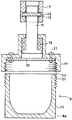
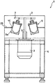
以下に、添付図面を参照して、本発明の実施の形態を詳細に説明する。尚、図1は本発明に係る被膜形成装置の稼動状態を示す図であり、(a)は装置の主要部を概略的に示す断面図、(b)は(a)の二点鎖線で示す部分Aを抜き出して示す平面図、図2は本発明に係る被膜形成装置の稼動していない状態を示す図であり、装置の主要部を概略的に示す断面図、図3は図2に示す被膜形成装置のB−B断面図であり、容器本体を容器ホルダから取り外して示す図、図4は図1に示す被膜形成装置において天板を取り外して示す平面図である。 Embodiments of the present invention will be described below in detail with reference to the accompanying drawings. FIG. 1 is a view showing the operating state of the film forming apparatus according to the present invention, (a) is a cross-sectional view schematically showing the main part of the apparatus, and (b) is shown by a two-dot chain line in (a). FIG. 2 is a diagram showing a state in which the coating film forming apparatus according to the present invention is not in operation, FIG. 2 is a cross-sectional view schematically showing the main part of the apparatus, and FIG. 3 is shown in FIG. It is BB sectional drawing of a film formation apparatus, the figure which removes a container main body from a container holder, and FIG. 4 is a top view which removes a top plate in the film formation apparatus shown in FIG.
本発明に係る被膜形成装置1は、ボール状の基材4の表面に二酸化チタン粉末(粉末)6を被覆してチタンボールを製造するものであり、装置上方の天板2に取り付けられたモータ3と、モータ3の出力軸5と、出力軸5に交差し且つ略水平に設けられたアーム7と、アーム7に揺動自在に吊下げられた揺動軸11と、揺動軸11の下端に取り付けられた容器9と、円環状に設けられたナイロン材の接触部10とを備えている。モータ3の出力軸5の下端は底板14の軸受け16に軸支されている。
A coating
アーム7は出力軸5を中心として平面視十字状に設けられており、アーム7には4つの容器9が吊下げられている。アーム7には容器9の揺動軸11が取り付けられており、揺動軸11に固定されたピン12がアーム7に形成された軸孔13に回動自在に軸支されている。
The
容器9は略円筒状の容器本体15と、揺動軸11に取り付けられた容器ホルダ17とを備え、容器ホルダ17にはベアリング19が組み込まれており、容器9が揺動軸11に対して回転自在になっている。容器9は真鍮、鉄、銅、SUS、金属チタンやアルミナ、ジルコニア、セラミック等の硬質体を用いる。
The
容器本体15の口部には雄ねじ(ねじ部)21が形成され、容器ホルダ17には雌ねじ(ねじ部)23が形成されており、容器本体15の口部を容器ホルダ17内にねじ込むことによって容器本体15を容器ホルダ17に固定している。
A male screw (threaded portion) 21 is formed at the mouth of the
容器ホルダ17には容器本体15の口部を塞ぐ蓋体25がねじ27固定されており、容器本体15内の二酸化チタン粉末6が容器ホルダ17側に移動するのを防止して、ベアリング19内に二酸化チタン粉末6が進入するのを防いでいる。
A
側板4には中央が円状に切り開かれた支持板29が固定されており、接触部10は支持板29の内周側端縁に沿って設けられている。
A
基材4の材料としては、ガラス、シリカ等のセラミック、鋼、銅、銀、アルミニウム等の金属及びその酸化物であるアルミナ、アルミナセラミック等の金属酸化物、エチレン、ポリプロピレン等の高分子樹脂、木質材の何れかを用いている。 Examples of the material of the base material 4 include glass, ceramics such as silica, metals such as steel, copper, silver, and aluminum, and metal oxides such as alumina and alumina ceramics thereof, polymer resins such as ethylene and polypropylene, One of the wood materials is used.
二酸化チタン粉末6は光触媒用の二酸化チタン粉末であり、アナターゼ型、ルチル型、
ブルッカイト型の何れであっても良い。また、二酸化チタン粉末6以外に、色変性化チタンの性能を阻害しない範囲で他の粉末原料を配合しても良く、特に光照射が少ない場所でも十分使用できるようにするため、色変性酸化チタンの触媒反応を高める波長の電磁波を発生する補助粉末を含めることが好ましい。電磁波を発生する粉末としては、天然に産出される千枚岩等に見られる低線量のマイクロ波を発生する鉱物又は天然ゼオライト、緑色ゼオライト等に見られる赤外線又は遠赤外線を発生する鉱物又は天然ゼオライト等が挙げられる。
Any of brookite type may be used. In addition to the
次に本実施の形態に係る被膜形成装置の作用及び効果を説明する。チタンボールの製造時には、まず容器本体15内に基材4と二酸化チタン粉末6を入れ、容器本体15を容器ホルダ17にねじ込んで固定する。モータ3の駆動により出力軸5が回転すると、出力軸5に取り付けられたアーム7が出力軸5回りに(図4中矢印C方向に)回転する。
Next, operations and effects of the film forming apparatus according to the present embodiment will be described. At the time of manufacturing the titanium balls, first, the base material 4 and the
アーム7が回転するとアーム7に取り付けた容器9が遠心力によって側板4方向に広がり、容器9の外側面9aが接触部10に接触する。容器9が接触部10に摩擦接触すると、容器9は矢印D方向に自転すると共に、二酸化チタン粉末6は容器9の公転運動と自転運動によって衝突及び摺擦を受ける。二酸化チタン粉末6が衝突と摺擦を受けると、二酸化チタン粉末6は色変性を起こして互いに圧着、及び基材4の表面に圧着して被膜を形成する。尚、二酸化チタン粉末6の衝突及び摺擦とは、二酸化粉末同士、粉末と基材、基材と基材、粉末と装置部材(容器壁)、基材と装置部材等の間で生じる衝突及び摺擦である。
When the
出力軸5の回転により容器9に生じる遠心力により容器9の公転半径が広がるので、接触部10が磨耗しても、容器外側面9aと接触部10との接触を保持でき、容器外側面9aと接触部10との間の接触圧が不安定になり難い。よって、容器9の回転ムラを防止できる。
Since the revolution radius of the
また、容器9はアーム7に揺動自在に吊下げられているので、従来技術のように容器の外側面9aと接触部10との接触位置の調整が不要である。
In addition, since the
出力軸5の回転により容器9に生じる遠心力により容器9の公転半径が広がるので、接触部10が多少磨耗しても、すぐに交換せずに接触部10を使用し続けることができ、接触部10の寿命を長くできる。
Since the revolution radius of the
容器本体15の口部をねじ込みによりホルダ17内に固定するので、容器9をアーム7に吊下げる際に、容器本体15とホルダとを接続具を用いて接続する必要がなく、接続作業が容易である。接触部10がナイロン材であるので、ゴム材に比べて耐久性に優れ、長期間の使用が可能となり経済的である。
Since the mouth of the
次に、他の実施の形態を説明する。第2実施の形態では、容器9内の収容物のみ第1実施の形態と異なり、他の構成は第1実施の形態と同様であるので、以下の説明において、上述した第1実施の形態と同一の作用効果を奏する部分には同一の符号を付することにより、その部分の詳細な説明を省略する。第2実施の形態では、容器9内に粒状又は塊状の二酸化チタン(被処理物)とジルコニア球(粉砕部材)を収納し、容器9が公転運動と自転運動することによって容器9内の粒状又は塊状の二酸化チタンが衝突と摺擦を繰り返し二酸化チタンは粉砕されて粉状になる。
Next, another embodiment will be described. In the second embodiment, only the contents in the
本実施の形態では、第1実施の形態と同様に接触部10が磨耗しても容器9の回転ムラを防止できると共に、容器の外側面9aと接触部10との接触位置の調整が不要である。また、接触部10が多少磨耗しても、すぐに交換せずに接触部10を使用し続けることができ接触部10の寿命を長くできる。
In the present embodiment, as in the first embodiment, even when the
容器本体15の口部をねじ込みによりホルダ17内に固定するので接続作業が容易である。接触部10がナイロン材であるので、ゴム材に比べて耐久性に優れ、長期間の使用が可能となり経済的である。
Since the mouth of the
尚、本発明は上述した実施の形態に限定されず、その要旨を逸脱しない範囲で種々の変形が可能である。第1及び第2実施の形態では、容器9はアーム7から4つ吊下げているが、図6に示すようにアーム7から吊下げる容器9は2つであっても10個であって良く、その数は制限されない。第1及び第2実施の形態では、モータ3はアーム7の上方に設けたが、図7に示すように、モータ3はアーム7の下方に設けてあっても良い。
The present invention is not limited to the above-described embodiments, and various modifications can be made without departing from the scope of the invention. In the first and second embodiments, four
第1実施の形態において基材4は、ボール形状に限らず、サイコロ形状、多角形状、星型形状(金平糖形状)、柱形状であっても良い。 In the first embodiment, the substrate 4 is not limited to the ball shape, but may be a dice shape, a polygonal shape, a star shape (gold flat sugar shape), or a column shape.
第2実施の形態において、粉砕部材はジルコニア球に限らず、球状の銅や真鍮であっても良い。また、被処理物は二酸化チタンに限らず、チタン酸バリウムや酸化バリウムであっても良い。 In the second embodiment, the pulverizing member is not limited to a zirconia sphere, and may be spherical copper or brass. Further, the object to be processed is not limited to titanium dioxide, but may be barium titanate or barium oxide.
1 被膜形成装置
3 モータ
4 基材
5 出力軸
6 粉末
7 アーム
9 容器
10 接触部
15 揺動軸
17 容器ホルダ
21 雄ねじ(ねじ部)
23 雌ねじ(ねじ部)
DESCRIPTION OF
23 Female thread (threaded part)
Claims (4)
The container includes a container main body and a container holder attached to the swing shaft. The container main body and the container holder are formed with screw parts, and the container main body is attached to the container holder by screwing the mouth of the container main body into the holder. The pulverizing apparatus according to claim 3, wherein the pulverizing apparatus is fixed to the pulverizer.
Priority Applications (1)
| Application Number | Priority Date | Filing Date | Title |
|---|---|---|---|
| JP2005226231A JP2007038156A (en) | 2005-08-04 | 2005-08-04 | Coating film forming device and crushing device |
Applications Claiming Priority (1)
| Application Number | Priority Date | Filing Date | Title |
|---|---|---|---|
| JP2005226231A JP2007038156A (en) | 2005-08-04 | 2005-08-04 | Coating film forming device and crushing device |
Publications (2)
| Publication Number | Publication Date |
|---|---|
| JP2007038156A true JP2007038156A (en) | 2007-02-15 |
| JP2007038156A5 JP2007038156A5 (en) | 2008-09-25 |
Family
ID=37796629
Family Applications (1)
| Application Number | Title | Priority Date | Filing Date |
|---|---|---|---|
| JP2005226231A Pending JP2007038156A (en) | 2005-08-04 | 2005-08-04 | Coating film forming device and crushing device |
Country Status (1)
| Country | Link |
|---|---|
| JP (1) | JP2007038156A (en) |
Cited By (4)
| Publication number | Priority date | Publication date | Assignee | Title |
|---|---|---|---|---|
| JP2008296159A (en) * | 2007-06-01 | 2008-12-11 | Minami Kk | Mixing and defoaming device |
| CN103551225A (en) * | 2013-11-04 | 2014-02-05 | 苏雷虹 | Planetary ball mill |
| JP2016006229A (en) * | 2008-11-21 | 2016-01-14 | アングロ プラチナム マーケティング リミテッド | Method for coating particles |
| CN113814040A (en) * | 2021-10-09 | 2021-12-21 | 合肥九晟机电科技有限公司 | Suspension type ball mill |
-
2005
- 2005-08-04 JP JP2005226231A patent/JP2007038156A/en active Pending
Cited By (4)
| Publication number | Priority date | Publication date | Assignee | Title |
|---|---|---|---|---|
| JP2008296159A (en) * | 2007-06-01 | 2008-12-11 | Minami Kk | Mixing and defoaming device |
| JP2016006229A (en) * | 2008-11-21 | 2016-01-14 | アングロ プラチナム マーケティング リミテッド | Method for coating particles |
| CN103551225A (en) * | 2013-11-04 | 2014-02-05 | 苏雷虹 | Planetary ball mill |
| CN113814040A (en) * | 2021-10-09 | 2021-12-21 | 合肥九晟机电科技有限公司 | Suspension type ball mill |
Similar Documents
| Publication | Publication Date | Title |
|---|---|---|
| JP2007038156A (en) | Coating film forming device and crushing device | |
| US5941636A (en) | Mixer having mixing blades capable of expanding automatically | |
| RU2682235C2 (en) | Grinding device for grindable products | |
| JP4873710B2 (en) | Rotating mixing container, pot lid and mixing method | |
| WO2014034613A1 (en) | Rotating classifier and vertical mill | |
| TW453912B (en) | Rocking press device | |
| JP2010194397A (en) | Sample crushing implement | |
| NL192951C (en) | Crusher. | |
| JP4862505B2 (en) | Forging apparatus and forging method | |
| JP4022203B2 (en) | Equipment for crushing materials such as spices and grains | |
| JP2001054846A (en) | Spherical surface working method and device thereof | |
| CN202478982U (en) | Macromolecule material grinding device | |
| WO2018168183A1 (en) | Pulverizer | |
| JP4923471B2 (en) | Cap with cutting tool | |
| JP2020131313A (en) | Barrel polishing device | |
| JP7237360B2 (en) | coating equipment | |
| KR200355885Y1 (en) | One body type milling hammer for hammer mill | |
| JP2013010100A (en) | Agitation treatment device | |
| JP2005040745A (en) | Disintegrating device | |
| JPS6134050Y2 (en) | ||
| JP2008284677A (en) | Machining tool | |
| JP2002238457A (en) | Method and apparatus for pulverizing tea leaf | |
| JP2011194324A (en) | Crusher | |
| CN218624709U (en) | Rotary swing device, fan and fan lamp | |
| JP6169504B2 (en) | Solid fuel crusher and roller support device |
Legal Events
| Date | Code | Title | Description |
|---|---|---|---|
| A621 | Written request for application examination |
Free format text: JAPANESE INTERMEDIATE CODE: A621 Effective date: 20070518 |
|
| RD02 | Notification of acceptance of power of attorney |
Free format text: JAPANESE INTERMEDIATE CODE: A7422 Effective date: 20070518 |
|
| A711 | Notification of change in applicant |
Free format text: JAPANESE INTERMEDIATE CODE: A711 Effective date: 20080714 |
|
| A521 | Written amendment |
Effective date: 20080724 Free format text: JAPANESE INTERMEDIATE CODE: A523 |
|
| A521 | Written amendment |
Effective date: 20080714 Free format text: JAPANESE INTERMEDIATE CODE: A821 |
|
| A977 | Report on retrieval |
Free format text: JAPANESE INTERMEDIATE CODE: A971007 Effective date: 20090311 |
|
| A131 | Notification of reasons for refusal |
Free format text: JAPANESE INTERMEDIATE CODE: A131 Effective date: 20090316 |
|
| A02 | Decision of refusal |
Free format text: JAPANESE INTERMEDIATE CODE: A02 Effective date: 20090709 |