JP2007032017A - Pile driving method and pile driving apparatus - Google Patents
Pile driving method and pile driving apparatus Download PDFInfo
- Publication number
- JP2007032017A JP2007032017A JP2005214476A JP2005214476A JP2007032017A JP 2007032017 A JP2007032017 A JP 2007032017A JP 2005214476 A JP2005214476 A JP 2005214476A JP 2005214476 A JP2005214476 A JP 2005214476A JP 2007032017 A JP2007032017 A JP 2007032017A
- Authority
- JP
- Japan
- Prior art keywords
- pile
- holder
- driving
- placing
- driving method
- Prior art date
- Legal status (The legal status is an assumption and is not a legal conclusion. Google has not performed a legal analysis and makes no representation as to the accuracy of the status listed.)
- Granted
Links
Images


Abstract
Description
本発明は、水底に杭を打設する杭打方法及び杭打装置に関するものである。 The present invention relates to a pile driving method and a pile driving apparatus for driving a pile to a water bottom.
従来、水底に杭を打設する杭打ち技術に関するものとして、特許第2521236号公報に記載されるように、打設すべき杭を吊り上げるためのクレーンを備えた杭打作業船を用い、その杭打作業船に位置決め手段を設けた杭打装置が知られている。この装置は、クレーンで吊り上げた杭を位置決め手段で保持しながら杭の位置決めを行い、杭の位置の微調整を実現しようとするものである。
しかしながら、このような杭打ち技術において、杭打作業船に対し杭の位置を微調整して位置決めし、杭を海底に打設する場合、潮位の変動により杭打作業船の垂直位置がずれると、杭の位置もずれを生じ、施工精度が低下するおそれがある。特に、杭を斜めに打設する場合に杭の位置ずれが大きくなるため、施工精度の低下も大きくなる。 However, in such a pile driving technology, if the position of the pile is finely adjusted and positioned with respect to the pile driving ship and the pile is placed on the seabed, the vertical position of the pile driving ship will shift due to fluctuations in the tide level. There is also a risk that the position of the pile will also shift and the construction accuracy will decrease. In particular, when the piles are placed diagonally, the displacement of the piles becomes large, so the deterioration of construction accuracy also increases.
また、杭打ちする際に杭の途中を保持するものであるため、杭に曲げ応力が生じやすい。例えば、杭を斜めに打設して斜杭とする場合には、杭の途中の保持部分に大きな曲げ応力が生じる。このため、この曲げ応力を低減して杭の変形を防止して杭の品質を確保することが望ましい。 Moreover, since it is what hold | maintains the middle of a pile when driving a pile, bending stress tends to arise in a pile. For example, when placing a pile diagonally and making it a slant pile, a big bending stress arises in the holding part in the middle of a pile. For this reason, it is desirable to reduce the bending stress to prevent the deformation of the pile and to ensure the quality of the pile.
そこで本発明は、このような技術課題を解決するためになされたものであって、水底への杭打ち作業において、施工精度の向上が図れ、また杭の品質を確保できる杭打方法及び杭打装置を提供することを目的とする。 Therefore, the present invention has been made to solve such a technical problem, and in pile driving work to the bottom of the water, it is possible to improve construction accuracy and to ensure pile quality and pile driving. An object is to provide an apparatus.
すなわち、本発明に係る杭打方法は、船体を用いて杭を水底に打設する杭打方法において、前記船体に設けられるパイルホルダにより前記杭を支持する支持工程と、前記杭を支持した状態で前記杭を水底に打設する際に、水位変動に応じ前記船体に対する前記パイルホルダの相対位置を移動させて前記杭の位置を保持する打設工程とを備えて構成されている。 That is, the pile driving method according to the present invention is a pile driving method in which a pile is placed on the bottom of a water using a hull. In a state in which the pile is supported by a pile holder provided in the hull, the pile is supported. When placing the pile on the bottom of the water, the construction includes a placing step of holding the position of the pile by moving the relative position of the pile holder with respect to the hull according to fluctuations in the water level.
この発明によれば、杭を水底に打設する際に水位変動に応じて船体に対するパイルホルダの相対位置を移動させて杭の位置を保持することにより、水位変動に応じて船体を移動させる必要がなく、杭を正確な打設位置に保持することができる。このため、杭打ち施工の精度の向上が図れる。 According to this invention, when placing the pile on the bottom of the water, it is necessary to move the hull according to the water level fluctuation by holding the position of the pile by moving the relative position of the pile holder with respect to the hull according to the water level fluctuation. The pile can be held in an accurate driving position. For this reason, the precision of pile driving construction can be improved.
また本発明に係る杭打方法において、前記打設工程にて、陸上から前記杭の位置を測定し、その測定位置から前記杭が移動しないように水位変動に応じて前記船体に対する前記パイルホルダの相対位置を移動させることが好ましい。 Further, in the pile driving method according to the present invention, in the placing step, the position of the pile is measured from the land, and the pile holder is relative to the hull according to the water level fluctuation so that the pile does not move from the measurement position. It is preferable to move the position.
この発明によれば、陸上から杭の位置を測定することにより、潮位の変化などの水位変動により水底に対する船体の位置変動及び杭の位置変動を正確に測定することができる。そして、水位変動により測定位置から杭が移動しないように船体に対するパイルホルダの相対位置を移動させることにより、杭を正確な打設位置に保持することができる。従って、杭打ち施工の精度の向上が図れる。 According to the present invention, by measuring the position of the pile from the land, it is possible to accurately measure the position fluctuation of the hull and the position fluctuation of the pile with respect to the water bottom due to the water level fluctuation such as a change in the tide level. And a pile can be hold | maintained in an exact placement position by moving the relative position of a pile holder with respect to a hull so that a pile may not move from a measurement position by water level fluctuation | variation. Therefore, the accuracy of pile driving construction can be improved.
また本発明に係る杭打方法は、杭を水底に打設する杭打方法であって、クレーンにより前記杭を吊り上げ、パイルホルダに前記杭を装着する装着工程と、前記パイルホルダにより前記杭の中間位置を把持し、前記パイルホルダを傾けて前記杭を斜めに支持する支持工程と、前記杭の吊り上げに用いた前記クレーンのロープ材を前記パイルホルダに設置される滑車に巻き掛け、そのロープ材を引き上げることにより前記杭を水底に圧入する圧入工程と、打設装置を用いて前記杭を水底に打設する打設工程とを備えて構成されている。 Further, the pile driving method according to the present invention is a pile driving method for placing a pile on a water bottom, lifting the pile by a crane, and mounting the pile on a pile holder; and an intermediate position of the pile by the pile holder A support step of tilting the pile holder to support the pile diagonally, wrapping the rope material of the crane used for lifting the pile around the pulley installed on the pile holder, and pulling up the rope material Are provided with a press-fitting process for press-fitting the pile into the bottom of the water and a placement process for placing the pile into the bottom of the water using a placement device.
この発明によれば、杭を打設する前に水底に圧入することにより、杭においてパイルホルダ把持部分より上方の部分を短くすることができ、杭の把持部分に生ずる曲げ応力の低減が図れる。このため、杭の変形及び杭の打設位置ずれを抑制でき、施工精度の向上が図れ、杭の品質の確保が可能となる。また、杭の吊り上げに用いたロープ材をパイルホルダの滑車に巻き掛けて引き上げるという簡易な作業によって、杭を容易に水底に圧入することができる。 According to this invention, by pressing into the water bottom before placing the pile, the portion above the pile holder gripping portion in the pile can be shortened, and the bending stress generated in the gripping portion of the pile can be reduced. For this reason, the deformation | transformation of a pile and the placement position shift of a pile can be suppressed, construction accuracy can be improved and the quality of a pile can be ensured. In addition, the pile can be easily press-fitted into the bottom of the water by a simple operation of winding the rope material used for lifting the pile around the pulley of the pile holder and pulling it up.
また本発明に係る杭打方法において、前記打設工程は、第一打設機を前記杭の頭部に取り付けて打設を行った後、前記第一打設機を取り外し前記第一打設機より重く打設力の大きい第二打設機を前記杭の頭部に取り付けて打設を行うことが好ましい。 Moreover, in the pile driving method according to the present invention, in the driving step, after the first driving machine is mounted on the head of the pile, the first driving machine is removed and the first driving machine is removed. It is preferable that the second driving machine, which is heavier than the machine and has a large driving force, is attached to the head of the pile to perform the driving.
この発明によれば、第一打設機を杭の頭部に取り付けて打設を行った後、第一打設機を取り外し第二打設機を杭の頭部に取り付けて打設を行う。すなわち、パイルホルダの把持位置より長く杭が突出する際に軽量の第一打設機を杭に取り付けて打設を行うことにより、杭の把持部分に生ずる曲げ応力を低減することができる。このため、杭の変形及び杭の打設位置ずれが抑制され、施工精度の向上が図れ、打設される杭の品質の確保が可能となる。 According to this invention, after placing the first placing machine on the head of the pile and placing it, the first placing machine is removed and the second placing machine is attached to the head of the pile and placed. . That is, when the pile protrudes longer than the pile holder gripping position, the bending stress generated in the gripping portion of the pile can be reduced by mounting the lightweight first placing machine on the pile. For this reason, the deformation | transformation of a pile and the placement position shift of a pile are suppressed, construction accuracy can be improved and the quality of the pile to be placed can be ensured.
また本発明に係る杭打方法は、杭を水底に打設する杭打方法において、パイルホルダにより前記杭の中間位置を把持し、前記パイルホルダを傾けて前記杭を斜めに支持するパイルホルダ支持工程と、打設装置を前記の杭の頭部に取り付け、前記打設装置を作動させて前記杭を水底に打ち込む打込工程と、前記杭の打ち込みにより前記打設装置が前記パイルホルダの位置まで降下してきた際に、前記杭の軸方向に向けて配置される前記パイルホルダのリーダ部に前記打設装置を係合させ前記リーダ部によって前記打設装置を上下動可能に支持し、前記パイルホルダの把持を解除するリーダ支持工程とを備えて構成されている。 Further, the pile driving method according to the present invention is a pile driving method in which the pile is driven to the bottom of the water, a pile holder supporting step of holding the pile obliquely by holding the intermediate position of the pile by a pile holder, and tilting the pile holder; The driving device is attached to the head of the pile, the driving device is operated to drive the pile into the bottom of the water, and the driving device is lowered to the position of the pile holder by driving the pile. In this case, the placement device is engaged with the leader portion of the pile holder arranged in the axial direction of the pile, and the placement device is supported by the leader portion so as to be movable up and down, and the grip of the pile holder is released. And a reader supporting process.
また本発明に係る杭打方法において、前記杭の上部には防食塗装が施されていることが好ましい。 Moreover, in the pile driving method according to the present invention, it is preferable that anticorrosion coating is applied to the upper portion of the pile.
これらの発明によれば、杭の打ち込みにより打設装置がパイルホルダの位置まで降下した際にパイルホルダの把持を解除し、パイルホルダのリーダ部により打設装置を上下動可能に支持する。このため、杭の上部に防食塗装が施されている場合にその防食塗装がパイルホルダの把持によって剥離するような不都合を回避できる。これにより、打設された杭の品質の確保が可能となる。 According to these inventions, when the driving device is lowered to the position of the pile holder by driving the pile, the gripping of the pile holder is released, and the driving device is supported by the leader portion of the pile holder so as to be movable up and down. For this reason, when the anti-corrosion coating is given to the upper part of the pile, the inconvenience that the anti-corrosion coating is peeled off by gripping the pile holder can be avoided. This makes it possible to ensure the quality of the placed pile.
また本発明に係る杭打装置は、杭を水底に打設する杭打装置において、前記杭の頭部に取り付けられ前記杭の打設を行う打設装置と、前記杭の軸方向に向けて配置されるリーダ部及び前記リーダ部に取り付けられ前記杭を把持する把持部を有するパイルホルダとを備えて構成され、前記リーダ部は、前記打設装置と係合し前記打設装置を摺動自在に支持するガイド機構を備えている。 Moreover, the pile driving device according to the present invention is a pile driving device for driving a pile to the bottom of the water, and a driving device that is attached to the head of the pile and that drives the pile, and is directed toward the axial direction of the pile. And a pile holder having a gripping portion attached to the leader portion and gripping the pile. The leader portion engages with the placement device and slides on the placement device. And a guide mechanism for supporting.
また本発明に係る杭打装置において、前記杭の上部には防食塗装が施されていることが好ましい。 Moreover, in the pile driving device according to the present invention, it is preferable that anticorrosion coating is applied to the upper portion of the pile.
これらの発明によれば、杭の打ち込みにより打設装置がパイルホルダの位置まで降下した際にパイルホルダの把持を解除し、パイルホルダのリーダ部により打設装置を摺動自在に支持することができる。このため、杭の上部に防食塗装が施されている場合にその防食塗装が把持部の把持によって剥離するような不都合を回避できる。これにより、打設された杭の品質の確保が可能となる。 According to these inventions, when the driving device is lowered to the position of the pile holder by driving the pile, the holding of the pile holder can be released, and the driving device can be slidably supported by the leader portion of the pile holder. For this reason, when the anticorrosion coating is given to the upper part of a pile, the inconvenience that the anticorrosion coating peels by the holding | grip of a holding part can be avoided. This makes it possible to ensure the quality of the placed pile.
本発明によれば、水底への杭打ちの施工精度の向上が図れ、また杭の品質を確保できる杭打方法及び杭打装置を提供することができる。 According to the present invention, it is possible to provide a pile driving method and a pile driving device that can improve the accuracy of pile driving to the bottom of the water and can ensure the quality of the pile.
以下、添付図面を参照して本発明の実施の形態を詳細に説明する。なお、図面の説明において同一の要素には同一の符号を付し、重複する説明を省略する。 Hereinafter, embodiments of the present invention will be described in detail with reference to the accompanying drawings. In the description of the drawings, the same elements are denoted by the same reference numerals, and redundant description is omitted.
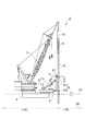
図1は本発明の実施形態に係る杭打装置の側面図である。 FIG. 1 is a side view of a pile driving device according to an embodiment of the present invention.
図1に示すように、本実施形態に係る杭打装置1は、船体2を用いて杭10を水底に打設する装置である。打設すべき杭10は、例えば鋼管杭が用いられる。杭10の上部には、防食塗装11が施されている。防食塗装11は、杭10の表面を錆などから保護する塗装である。この防食塗装11は、好ましくは、厚く塗装することで重防食塗装される。
As shown in FIG. 1, a
杭打装置1は、船体2にクレーン3及びパイルホルダ4を備えて構成されている。船体2は、クレーン3を備えた起重機船が用いられる。クレーン3は、打設すべき杭10を吊り上げ可能なものが用いられ、例えば船体2上で旋回可能なジブクレーンが用いられる。
The
パイルホルダ4は、杭10を支持する支持部材であり、船体2上に設けられている。パイルホルダ4は、リーダ部5、把持部6及びアーム部7を備えて構成されている。リーダ部5は、杭10の軸方向に向けて配置される長尺状の部材である。リーダ部5には、杭10を把持する把持部6が設けられている。把持部6は、杭10をリーダ部5に対し上下動可能に支持するものである。この把持部6としては、例えば上部ホルダ61及び下部ホルダ62を備えたものが用いられる。
The
上部ホルダ61は、リーダ部5の上部位置に取り付けられている。下部ホルダ62は、上部ホルダ62の下方位置であって、リーダ部5の下部位置に取り付けられている。上部ホルダ61及び下部ホルダ62は、杭10の外周を被うように装着され、杭10の軸方向の移動を許容しつつ径方向の移動を禁止する。
The
アーム部7は、船体2に取り付けられ、リーダ部5を支持する部材である。アーム部7は、上部アーム71及び下部アーム72を備えて構成されている。上部アーム71は、その先端がリーダ部5の上部位置に回動自在に取り付けられ、リーダ部5の上部を支持する。下部アーム72は、その先端がリーダ部5の下部位置に回動自在に取り付けられ、リーダ部5の下部を支持する。例えば、下部アーム72は、水平方向に向けて配置され、先端が船体2から突出するように設けられている。また、上部アーム71は、基端が下部アーム72の基端の近傍に回動自在に取り付けられ、その先端側を斜め上方とし傾斜して配置されている。この上部アーム71は、その先端が船体2から突出するように設けられている。
The
上部アーム71及び下部アーム72は、軸方向に対し伸縮可能に構成されている。例えば、上部アーム71及び下部アーム72は、油圧シリンダを内蔵し、この油圧シリンダの伸縮に応じて伸縮可能に構成される。上部アーム71及び下部アーム72を適宜伸縮させることにより、リーダ部5を水平移動させることができ、またリーダ部5の姿勢を変更することができる。リーダ部5には、滑車装置51が設けられている。滑車装置51は、杭10の強制自沈、すなわち圧入の際に用いられるものであり、例えばリーダ部5の上端に設けられる。
The
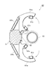
図2、3は、本実施形態に係る杭打装置1の把持部6の説明図であり、図1における上部ホルダ61のII−IIの水平断面を示している。
2 and 3 are explanatory views of the
図2は上部ホルダ61により杭10を支持した状態を示したものであり、図3は上部ホルダ61を開放して上部ホルダ61による杭10の支持の解除を示したものである。上部ホルダ61は、二つの可動部61a、61aを備えている。可動部61aは、半円弧状を呈しており、一端がリーダ部5に軸着され回動自在に取り付けられている。可動部61aには、油圧シリンダ61bが取り付けられている。
FIG. 2 shows a state in which the
油圧シリンダ61bは、その一端がリーダ部5に回動自在に取り付けられ、他端が可動部61aに回動自在に取り付けられている。図2のように、油圧シリンダ61bが伸長することにより、可動部61aが閉じられ、杭10の外周に位置する。これにより、二つの可動部61a、61aが杭10を囲むように円弧状となり、杭10の外周を支持する。可動部61aの内周面には、ローラ61cが設けられている。ローラ61cは、杭10に直接接触するものであり、杭10を軸方向への移動を許容し、径方向の移動を規制する。このローラ61cは、杭10の周方向に向けた支軸を中心に回動自在に取り付けられている。
One end of the
図3に示すように、油圧シリンダ61bが収縮することにより、可動部61aが開かれ、ローラ61cが杭10の外周面から離間する。これにより、杭10の外周支持が解除される。このとき、可動部61aは、杭10及びその杭10に取り付けた第二ハンマ30が接触しないように、開かれる。以上、上部ホルダ61について詳述したが、下部ホルダ62も上部ホルダ61と同様に構成すればよい。
As shown in FIG. 3, when the
図3に示すように、リーダ部5には、その軸方向に向けて延びるガイドレール52が形成されている。ガイドレール52は、杭10の取り付けられる打設装置である第二ハンマ30を摺動自在に支持するガイド機構として機能するものである。このガイドレール52は、例えば、リーダ部5の側壁を杭10側に突出して形成され、突出した先端の両縁を外側に張り出した形状となっている。第二ハンマ30には、ガイドレール52に係合する係合部31が形成されている。係合部31は、ガイドレール52と係合する長溝32が形成されている。
As shown in FIG. 3, a
次に、本実施形態に係る杭打装置1の動作及び本実施形態に係る杭打方法について説明する。
Next, the operation of the
図1に示すように、まず、パイルホルダ4に杭10がセットされる。杭10にロープ12が取り付けられ、このロープ12を介してクレーン3で杭10が吊り上げられる。そして、杭10は、パイルホルダ4に装着される。すなわち、上部ホルダ61及び下部ホルダ62が開かれ、杭10がパイルホルダ4の支持位置に移動された後、上部ホルダ61及び下部ホルダ62が閉じられる。これにより、杭10は、パイルホルダ4により支持され、軸方向に対して移動可能となりつつ、径方向への移動が規制される。
As shown in FIG. 1, first, a
なお、パイルホルダ4への杭10のセットを行う際に、船体2は、図示しないアンカにより水平方向に移動しないように留められている。
In addition, when setting the
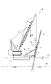
そして、図4に示すように、施工予定の角度に杭10が傾けられる。この傾け作業は、アーム部7の上部アーム71及び下部アーム72を適宜伸縮させることにより行われる。例えば、上部アーム71の伸長量を下部アーム72の伸長量より大きくすることにより、垂直になっていた杭10が徐々に傾斜していく。このような杭10の傾け作業によって、杭10が所定の施工角度に傾けられる。
Then, as shown in FIG. 4, the
そして、パイルホルダ4により支持された杭10は、その自重により海底90内に沈下していく。その際、パイルホルダ4は、杭10の軸方向に移動を許容しているので、杭10は海底90を自重によって沈下することができる。
And the
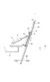
そして、図5に示すように、杭10の自重による沈下が止まったら、杭10の強制沈下が行われる。すなわち、杭10を吊り上げていたロープ12が下げられ、その途中部分が滑車装置51に掛け回される。この状態において、クレーン3によりロープ12が引き上げられる。この引き上げによって、ロープ12によって杭10が下方へ引き下げられ、杭10が海底90内に圧入されていく。これにより、傾斜する杭10について、その中間位置を支持する把持部6より上方の部分を短くすることができ、杭10の把持部6の支持位置に生ずる曲げ応力の低減が図れる。なお、この杭10の強制沈下は、施工状況に応じて行わない場合もある。
Then, as shown in FIG. 5, when the settlement due to the weight of the
そして、図6に示すように、第一ハンマ20による杭打ち工程が行われる。第一ハンマ20は、杭10の頭部に装着可能なパイルキャップ21を備えた打設装置である。第一ハンマ20としては、例えば油圧ハンマが用いられる。クレーン3などを用いて第一ハンマ20が杭10の頭部に取り付けられる。そして、第一ハンマ20を作動させ、杭10の下方に打撃力を付与することにより、杭10が海底90内に打ち込まれていく。
And the pile driving process by the
そして、図7に示すように、杭10の頭部がリーダ部5の近くに来るまで杭10が打ち込まれたら、第一ハンマ20が杭10から取り外され、その代わりに第二ハンマ30が杭10の頭部に取り付けられる。そして、第二ハンマ30による杭打ち工程が行われる。第二ハンマ30は、杭10の頭部に装着可能なパイルキャップ33を備えた打設装置であって、第一ハンマ20より重く打設力の大きいものである。第二ハンマ30としては、例えば油圧ハンマが用いられる。杭10の頭部に取り付けた第二ハンマ30を作動させ、杭10の下方に打撃力を付与することにより、杭10が海底90内に打ち込まれていく。
Then, as shown in FIG. 7, when the
そして、図8に示すように、杭10の打ち込みにより第二ハンマ30がパイルホルダ4の位置まで降下してきたら、リーダ部5により第二ハンマ30を通じて杭10の支持が行われる。すなわち、パイルホルダ4のリーダ部5に第二ハンマ30が係合され、リーダ部5によって第二ハンマ30及び杭10が上下動可能に支持される。具体的に説明すると、杭10の打ち込みにより第二ハンマ30がパイルホルダ4の近くまで降下してきたら、図3に示すように、上部ホルダ61を開き、リーダ部5のガイドレール52に第二ハンマ30の係合部を係合させ、リーダ部5に対し第二ハンマ30を摺動可能に支持する。これによって、杭10がリーダ部5の軸方向に移動可能としつつ、その径方向に移動しないように拘束することができる。このとき、図8に示すように、下部ホルダ62は閉じた状態として、杭10の支持を継続しておく。
Then, as shown in FIG. 8, when the
そして、第二ハンマ30の作動により杭10の打ち込みが行われ、第二ハンマ30が下部ホルダ62の近傍位置まで来たら、下部ホルダ62を開いて杭10の打ち込みを続行する。そして、杭10が所望の施工位置まで打ち込まれたら、打設作業を終了する。
Then, the
このような第一ハンマ20及び第二ハンマ30による杭10の打設、または杭10の自重沈下及び強制沈下の際に、潮位の変動により水面91が上下する場合がある。この場合、船体2がアンカにより水平方向に移動しないとしても、船体2が上下することとなる。その際、パイルホルダ4を通じて杭10を斜めに支持していると、水面91の上下により、杭10の水平位置にずれを生ずる。これに対し、船体2に対しパイルホルダ4のリーダ部5の相対位置を移動させることにより杭10の位置が保持される。すなわち、水位変動に応じて杭10が移動しないように、アーム部7を適宜伸縮させることにより、杭10の位置を保持することができる。
When the
その際に、陸上から杭10の位置を測定し、その測定位置から杭10が移動しないように水位変動に応じて船体2に対するパイルホルダ4のリーダ部5の相対位置を移動させることが好ましい。この場合、陸上から杭10の位置を測定することにより、杭10の位置を正確に計測することができる。
At that time, it is preferable to measure the position of the
以上のように、本実施形態に係る杭打方法によれば、杭10を海底90に打設する際に水位変動に応じて船体2に対するパイルホルダ4及び杭10の相対位置を移動させて杭10の位置を保持することができる。これにより、潮位などの水位変動に応じて船体2を水平方向に移動させる必要がなく、杭10を正確な打設位置に保持することができる。このため、杭打ち施工の精度の向上が図れる。
As described above, according to the pile driving method according to the present embodiment, when the
また、陸上から杭10の位置を測定することにより、潮位の変化などの水位変動により水底に対する船体2の位置変動及び杭の位置変動を正確に測定することができる。そして、水位変動により測定位置から杭10が移動しないように船体2に対するパイルホルダ4及び杭10の相対位置を移動させることにより、杭10を正確な打設位置に保持することができる。従って、杭打ち施工の精度の向上が図れる。
Further, by measuring the position of the
また本実施形態に係る杭打方法によれば、杭10の吊り上げに用いたロープ12をパイルホルダ4に設置される滑車装置51に巻き掛け、そのロープ12を引き上げて杭10を水底に圧入する。これにより、杭10においてパイルホルダ把持部分より上方の部分を短くすることができ、杭10の把持部分に生ずる曲げ応力(曲げモーメント)の低減が図れる。このため、杭10の変形及び杭10の打設位置ずれを抑制でき、施工精度の向上が図れ、杭の品質の確保が可能となる。また、杭10の吊り上げに用いたロープ12をパイルホルダ4の滑車装置51に巻き掛けて引き上げるという簡易な作業によって、杭10を容易に水底に圧入することができる。
Moreover, according to the pile driving method which concerns on this embodiment, the
また本実施形態に係る杭打方法によれば、第一ハンマ20を杭10の頭部に取り付けて打設を行った後、第一ハンマ20を取り外し第二ハンマ30を杭10の頭部に取り付けて打設を行う。すなわち、パイルホルダ4の把持位置より長く杭10が突出する際に軽量の第一ハンマ20を杭10に取り付けて打設を行うことにより、杭10の把持部分に生ずる曲げ応力を低減することができる。このため、杭10の変形及び杭10の打設位置ずれが抑制され、施工精度の向上が図れ、打設される杭の品質の確保が可能となる。
Moreover, according to the pile driving method according to the present embodiment, after the
また本実施形態に係る杭打方法及び杭打装置によれば、杭10の打ち込みにより第二ハンマ30がパイルホルダ4の位置まで降下した際に、パイルホルダ4のリーダ部5により第二ハンマ30を上下動可能に支持し、パイルホルダ4により把持を解除する。このため、杭10の上部に防食塗装11が施されている場合にその防食塗装11がパイルホルダ4の把持によって剥離するような不都合を回避できる。これにより、打設された杭の品質の確保が可能となる。
Further, according to the pile driving method and the pile driving apparatus according to the present embodiment, when the
なお、本実施形態は本発明に係る杭打方法及び杭打装置の一実施形態を示したものであり、本発明に係る杭打方法及び杭打装置は、このようなものに限定されるものではなく、各請求項に記載される発明の要旨を変更しない程度に実施形態に係る杭打方法及び杭打装置を変形したものであってもよい。 In addition, this embodiment shows one Embodiment of the pile driving method and the pile driving device which concern on this invention, and the pile driving method and the pile driving device which concern on this invention are limited to such a thing. Instead, the pile driving method and the pile driving apparatus according to the embodiment may be modified to the extent that the gist of the invention described in each claim is not changed.
例えば、本実施形態では、杭10を海底90に打設する場合について説明したが、杭10を湖や河川などの水底に打設する場合に適用してもよい。
For example, in the present embodiment, the case where the
また、本実施形態では、起重機船である船体2を用いて杭10を水底に打設する杭打方法及び杭打装置について説明したが、自走可能なクレーンを船体に搭載したものを用いて杭10を打設する場合であってもよい。また、クレーンを桟橋や埠頭などの構造物に設置して杭10を打設する場合に適用してもよい。
Moreover, although this embodiment demonstrated the pile driving method and the pile driving device which drive the
1…杭打装置
2…船体
3…クレーン
4…パイルホルダ
5…リーダ部
6…把持部
7…アーム部
10…杭
11…防食塗装
12…ロープ
20…第一ハンマ
30…第二ハンマ
31…係合部
51…滑車装置
52…ガイドレール
90…海底
91…水面。
DESCRIPTION OF
Claims (8)
前記船体に設けられるパイルホルダにより前記杭を支持する支持工程と、
前記杭を支持した状態で前記杭を水底に打設する際に、水位変動に応じ前記船体に対する前記パイルホルダの相対位置を移動させて前記杭の位置を保持する打設工程と、
を備えることを特徴とする杭打方法。 In the pile driving method in which the pile is driven to the bottom of the water using the hull,
A support step of supporting the pile by a pile holder provided in the hull;
When placing the pile on the bottom of the water in a state where the pile is supported, a placing step of maintaining the position of the pile by moving the relative position of the pile holder with respect to the hull according to fluctuations in the water level;
A pile driving method characterized by comprising:
クレーンにより前記杭を吊り上げ、パイルホルダに前記杭を装着する装着工程と、
前記パイルホルダにより前記杭の中間位置を把持し、前記パイルホルダを傾けて前記杭を斜めに支持する支持工程と、
前記杭の吊り上げに用いた前記クレーンのロープ材を前記パイルホルダに設置される滑車に巻き掛け、そのロープ材を引き上げることにより前記杭を水底に圧入する圧入工程と、
打設装置を用いて前記杭を水底に打設する打設工程と、
を備えた杭打方法。 In the pile driving method in which the pile is driven to the bottom of the water,
A mounting step of lifting the pile by a crane and mounting the pile on a pile holder;
A support step of gripping the intermediate position of the pile by the pile holder, and tilting the pile holder to support the pile diagonally;
A press-fitting step of press-fitting the pile into the water bottom by winding the rope material of the crane used for lifting the pile around a pulley installed on the pile holder, and pulling up the rope material;
A placing step of placing the pile on the bottom of the water using a placing device;
Pile driving method with.
パイルホルダにより前記杭の中間位置を把持し、前記パイルホルダを傾けて前記杭を斜めに支持するパイルホルダ支持工程と、
打設装置を前記の杭の頭部に取り付け、前記打設装置を作動させて前記杭を水底に打ち込む打込工程と、
前記杭の打ち込みにより前記打設装置が前記パイルホルダの位置まで降下してきた際に、前記杭の軸方向に向けて配置される前記パイルホルダのリーダ部に前記打設装置を係合させ前記リーダ部によって前記打設装置を上下動可能に支持し、前記パイルホルダの把持を解除するリーダ支持工程と、
を備えた杭打方法。 In the pile driving method in which the pile is driven to the bottom of the water,
A pile holder supporting step of gripping an intermediate position of the pile by a pile holder, tilting the pile holder and supporting the pile diagonally;
A driving step of attaching a driving device to the head of the pile and operating the driving device to drive the pile into the water bottom;
When the driving device is lowered to the position of the pile holder by driving the pile, the driving device is engaged with the leader portion of the pile holder arranged in the axial direction of the pile, and the leader portion A leader supporting step of supporting the placing device so as to be movable up and down and releasing gripping of the pile holder;
Pile driving method with.
前記杭の頭部に取り付けられ前記杭の打設を行う打設装置と、
前記杭の軸方向に向けて配置されるリーダ部及び前記リーダ部に取り付けられ前記杭を把持する把持部を有するパイルホルダと、
を備えて構成され、
前記リーダ部は、前記打設装置と係合し前記打設装置を摺動自在に支持するガイド機構を備えていること、
を特徴とする杭打装置。 In the pile driving device that drives the pile to the bottom of the water,
A placing device attached to the head of the pile and placing the pile;
A pile holder having a leader part arranged in the axial direction of the pile and a grip part attached to the leader part to grip the pile;
Configured with
The leader portion includes a guide mechanism that engages with the placement device and slidably supports the placement device;
Pile driving device characterized by
The pile driving device according to claim 7, wherein anticorrosion coating is applied to an upper portion of the pile.
Priority Applications (1)
| Application Number | Priority Date | Filing Date | Title |
|---|---|---|---|
| JP2005214476A JP4566850B2 (en) | 2005-07-25 | 2005-07-25 | Stakeout method |
Applications Claiming Priority (1)
| Application Number | Priority Date | Filing Date | Title |
|---|---|---|---|
| JP2005214476A JP4566850B2 (en) | 2005-07-25 | 2005-07-25 | Stakeout method |
Publications (2)
| Publication Number | Publication Date |
|---|---|
| JP2007032017A true JP2007032017A (en) | 2007-02-08 |
| JP4566850B2 JP4566850B2 (en) | 2010-10-20 |
Family
ID=37791596
Family Applications (1)
| Application Number | Title | Priority Date | Filing Date |
|---|---|---|---|
| JP2005214476A Expired - Fee Related JP4566850B2 (en) | 2005-07-25 | 2005-07-25 | Stakeout method |
Country Status (1)
| Country | Link |
|---|---|
| JP (1) | JP4566850B2 (en) |
Cited By (15)
| Publication number | Priority date | Publication date | Assignee | Title |
|---|---|---|---|---|
| JPS6093072A (en) * | 1983-10-27 | 1985-05-24 | 株式会社東芝 | Method of detecting holiday of elevator |
| WO2008099651A1 (en) | 2007-02-13 | 2008-08-21 | Toyota Jidosha Kabushiki Kaisha | Process for producing aluminum alloy material and heat treated aluminum alloy material |
| CN102312438A (en) * | 2010-07-02 | 2012-01-11 | 南通市海洋水建工程有限公司 | Piling construction equipment for large steel pipe piles of seaborn intertidal zone wind power station |
| JP2012255279A (en) * | 2011-06-08 | 2012-12-27 | Shimizu Corp | Pile driving pontoon |
| JP2015014156A (en) * | 2013-07-05 | 2015-01-22 | 株式会社横山基礎工事 | Pier construction method and pile material guide structure |
| JP6063538B1 (en) * | 2015-09-17 | 2017-01-18 | 株式会社ミック | Hydraulic press-fitting and drawing device for steel sheet pile |
| WO2018117846A1 (en) * | 2016-12-23 | 2018-06-28 | Itrec B.V. | A method for installation of a pile adapted to support an offshore wind turbine, wave-induced motion compensated pile holding system, vessel, and pile holder |
| CN109371965A (en) * | 2018-11-13 | 2019-02-22 | 南通市海洋水建工程有限公司 | A kind of precise positioning pile sinking stable platform stake and its installation method |
| EP3517479A1 (en) * | 2018-01-30 | 2019-07-31 | GeoSea NV | Device and method for providing a sizeable, slender object with a longitudinal direction into an underwater bottom |
| WO2019125172A3 (en) * | 2017-12-22 | 2019-10-10 | Itrec B.V. | Pile holding system |
| WO2019172752A3 (en) * | 2018-03-06 | 2019-10-24 | Itrec B.V. | Adjustable pile holding system, vessel and pile installation method |
| US20210381189A1 (en) * | 2013-07-18 | 2021-12-09 | Gregory Enterprises, Incorporated | Pile lifting apparatus and method |
| US20220177081A1 (en) * | 2019-04-15 | 2022-06-09 | Itrec B.V. | Vessel and method for installation of a pile adapted to support an offshore wind turbine |
| WO2022253031A1 (en) * | 2021-06-02 | 2022-12-08 | 中交第四航务工程局有限公司 | Pile stabilization frame for pile driving of offshore wind power inclined pile group and pile driving method |
| EP4083328A4 (en) * | 2019-12-24 | 2023-01-04 | Jiangsu Goldwind Science & Technology Co., Ltd. | Monopile foundation guiding device |
Families Citing this family (1)
| Publication number | Priority date | Publication date | Assignee | Title |
|---|---|---|---|---|
| CN103661827A (en) * | 2013-12-27 | 2014-03-26 | 天津港航工程有限公司 | Installation system and construction method of wind turbine assembly in sea intertidal zone |
Citations (6)
| Publication number | Priority date | Publication date | Assignee | Title |
|---|---|---|---|---|
| JPS5049205U (en) * | 1973-08-31 | 1975-05-14 | ||
| JPS57201420A (en) * | 1981-06-02 | 1982-12-09 | Kubota Ltd | Driving of pile |
| JPS61146535U (en) * | 1985-02-25 | 1986-09-10 | ||
| JPH0412541U (en) * | 1990-05-18 | 1992-01-31 | ||
| JPH0516279Y2 (en) * | 1985-03-04 | 1993-04-28 | ||
| JP2002021077A (en) * | 2000-07-03 | 2002-01-23 | Unico Corporation | Method for observing location of columnar object |
-
2005
- 2005-07-25 JP JP2005214476A patent/JP4566850B2/en not_active Expired - Fee Related
Patent Citations (6)
| Publication number | Priority date | Publication date | Assignee | Title |
|---|---|---|---|---|
| JPS5049205U (en) * | 1973-08-31 | 1975-05-14 | ||
| JPS57201420A (en) * | 1981-06-02 | 1982-12-09 | Kubota Ltd | Driving of pile |
| JPS61146535U (en) * | 1985-02-25 | 1986-09-10 | ||
| JPH0516279Y2 (en) * | 1985-03-04 | 1993-04-28 | ||
| JPH0412541U (en) * | 1990-05-18 | 1992-01-31 | ||
| JP2002021077A (en) * | 2000-07-03 | 2002-01-23 | Unico Corporation | Method for observing location of columnar object |
Cited By (31)
| Publication number | Priority date | Publication date | Assignee | Title |
|---|---|---|---|---|
| JPS6093072A (en) * | 1983-10-27 | 1985-05-24 | 株式会社東芝 | Method of detecting holiday of elevator |
| WO2008099651A1 (en) | 2007-02-13 | 2008-08-21 | Toyota Jidosha Kabushiki Kaisha | Process for producing aluminum alloy material and heat treated aluminum alloy material |
| CN102312438A (en) * | 2010-07-02 | 2012-01-11 | 南通市海洋水建工程有限公司 | Piling construction equipment for large steel pipe piles of seaborn intertidal zone wind power station |
| JP2012255279A (en) * | 2011-06-08 | 2012-12-27 | Shimizu Corp | Pile driving pontoon |
| JP2015014156A (en) * | 2013-07-05 | 2015-01-22 | 株式会社横山基礎工事 | Pier construction method and pile material guide structure |
| US20210381189A1 (en) * | 2013-07-18 | 2021-12-09 | Gregory Enterprises, Incorporated | Pile lifting apparatus and method |
| JP6063538B1 (en) * | 2015-09-17 | 2017-01-18 | 株式会社ミック | Hydraulic press-fitting and drawing device for steel sheet pile |
| WO2018117846A1 (en) * | 2016-12-23 | 2018-06-28 | Itrec B.V. | A method for installation of a pile adapted to support an offshore wind turbine, wave-induced motion compensated pile holding system, vessel, and pile holder |
| US11008726B2 (en) | 2016-12-23 | 2021-05-18 | Itrec B.V. | Method for installation of a pile adapted to support an offshore wind turbine, wave-induced motion compensated pile holding system, vessel, and pile holder |
| CN110325776A (en) * | 2016-12-23 | 2019-10-11 | 伊特里克公司 | Method of installing a pile adapted to support an offshore wind turbine, wave induced motion compensated pile holding system, vessel and pile holding device |
| EP4230800A3 (en) * | 2017-12-22 | 2024-01-17 | Itrec B.V. | Pile holding system, vessel and pile installation method |
| JP7295862B2 (en) | 2017-12-22 | 2023-06-21 | イーテーエルエーセー・ベー・フェー | pile retention system |
| WO2019125172A3 (en) * | 2017-12-22 | 2019-10-10 | Itrec B.V. | Pile holding system |
| US11293158B2 (en) | 2017-12-22 | 2022-04-05 | Itrec B.V. | Pile holding system |
| JP2021508792A (en) * | 2017-12-22 | 2021-03-11 | イーテーエルエーセー・ベー・フェー | Pile holding system |
| US11492772B2 (en) | 2018-01-30 | 2022-11-08 | Deme Offshore Be Nv | Device and method for providing a sizeable, slender object with a longitudinal direction into an underwater bottom |
| TWI797245B (en) * | 2018-01-30 | 2023-04-01 | 比利時商黛咪離岸Be公司 | Device and method for providing a sizeable, slender object with a longitudinal direction into an underwater bottom |
| CN111867962A (en) * | 2018-01-30 | 2020-10-30 | 德米海洋比利时有限公司 | Device and method for positioning a substantially large elongate object having a longitudinal direction into a water bottom |
| CN111867962B (en) * | 2018-01-30 | 2023-08-18 | 德米海洋比利时有限公司 | Device and method for setting a substantially elongated object having a longitudinal direction into a water bottom |
| JP2021512831A (en) * | 2018-01-30 | 2021-05-20 | ディーム・オフショア・ベーエー・エヌ・ヴェー | Devices and methods for providing large, elongated objects with longitudinal directions into the bottom of the water |
| EP3517479A1 (en) * | 2018-01-30 | 2019-07-31 | GeoSea NV | Device and method for providing a sizeable, slender object with a longitudinal direction into an underwater bottom |
| WO2019149674A1 (en) * | 2018-01-30 | 2019-08-08 | GeoSea N.V. | Device and method for providing a sizeable, slender object with a longitudinal direction into an underwater bottom |
| US11313096B2 (en) | 2018-03-06 | 2022-04-26 | Itrec B.V. | Adjustable pile holding system, vessel and pile installation method |
| EP4105387A1 (en) * | 2018-03-06 | 2022-12-21 | Itrec B.V. | Adjustable pile holding system, vessel and pile installation method |
| WO2019172752A3 (en) * | 2018-03-06 | 2019-10-24 | Itrec B.V. | Adjustable pile holding system, vessel and pile installation method |
| US11795650B2 (en) | 2018-03-06 | 2023-10-24 | Itrec B.V. | Adjustable pile holding system, vessel and pile installation method |
| CN109371965A (en) * | 2018-11-13 | 2019-02-22 | 南通市海洋水建工程有限公司 | A kind of precise positioning pile sinking stable platform stake and its installation method |
| US20220177081A1 (en) * | 2019-04-15 | 2022-06-09 | Itrec B.V. | Vessel and method for installation of a pile adapted to support an offshore wind turbine |
| EP4083328A4 (en) * | 2019-12-24 | 2023-01-04 | Jiangsu Goldwind Science & Technology Co., Ltd. | Monopile foundation guiding device |
| US11718970B2 (en) | 2019-12-24 | 2023-08-08 | Jiangsu Goldwind Science & Technology Co., Ltd. | Monopile foundation guiding device |
| WO2022253031A1 (en) * | 2021-06-02 | 2022-12-08 | 中交第四航务工程局有限公司 | Pile stabilization frame for pile driving of offshore wind power inclined pile group and pile driving method |
Also Published As
| Publication number | Publication date |
|---|---|
| JP4566850B2 (en) | 2010-10-20 |
Similar Documents
| Publication | Publication Date | Title |
|---|---|---|
| JP4566850B2 (en) | Stakeout method | |
| EP3517479B1 (en) | Device and method for providing a sizeable, slender object with a longitudinal direction into an underwater bottom | |
| JP4838885B2 (en) | Offshore wind power generator construction method and construction equipment | |
| KR101463188B1 (en) | Working system for floating structure, floating structure, working ship, and working method for floating structure | |
| EP3018087B1 (en) | Hoisting device | |
| US10161095B2 (en) | Device and method for assembling a structure | |
| CN112771238B (en) | Device and method for erecting a tubular element having a longitudinal direction from a support surface at an outer end | |
| JP2007155739A5 (en) | ||
| NO325043B1 (en) | Method and apparatus for placing objects on the seabed | |
| EP3483342A1 (en) | Device and method for arranging a secondary construction on an offshore primary construction | |
| CN105951832A (en) | Diesel hammer deviation piling rectification construction process and equipment | |
| JP2023548724A (en) | System and method for controlling motion compensated pile guides for floating ships and ships | |
| KR101415752B1 (en) | Underwater work assembly and method for anchoring thereof | |
| JP4406375B2 (en) | Pile placement method, trolley and placement guide used for this | |
| JP2004027548A (en) | Pile driving guide and pile driving method | |
| EP4229241A1 (en) | Pile holding system and method | |
| JP2789024B2 (en) | Underwater pile driving device | |
| JP2006063684A (en) | Pile driving boat and pile driving method | |
| NZ593737A (en) | Installing an underwater screw anchor using gantry with motion compensation means | |
| EP4240964A1 (en) | Vessel and method for upending a monopile of an offshore wind turbine | |
| JPH09250132A (en) | Steel pipe pile driving method | |
| JP2004044199A (en) | Construction method for jacket structure and level adjusting apparatus | |
| JP2015158111A (en) | Drilling device, drilling method, and guide device | |
| JP2024007487A (en) | Method for arranging foundation in underwater bottom part from vessel | |
| WO2023072634A1 (en) | Installation of a monopile that is adapted to support an offshore wind turbine |
Legal Events
| Date | Code | Title | Description |
|---|---|---|---|
| A621 | Written request for application examination |
Free format text: JAPANESE INTERMEDIATE CODE: A621 Effective date: 20080407 |
|
| A977 | Report on retrieval |
Free format text: JAPANESE INTERMEDIATE CODE: A971007 Effective date: 20100226 |
|
| A131 | Notification of reasons for refusal |
Free format text: JAPANESE INTERMEDIATE CODE: A131 Effective date: 20100309 |
|
| A521 | Request for written amendment filed |
Free format text: JAPANESE INTERMEDIATE CODE: A523 Effective date: 20100428 |
|
| TRDD | Decision of grant or rejection written | ||
| A01 | Written decision to grant a patent or to grant a registration (utility model) |
Free format text: JAPANESE INTERMEDIATE CODE: A01 Effective date: 20100803 |
|
| A01 | Written decision to grant a patent or to grant a registration (utility model) |
Free format text: JAPANESE INTERMEDIATE CODE: A01 |
|
| A61 | First payment of annual fees (during grant procedure) |
Free format text: JAPANESE INTERMEDIATE CODE: A61 Effective date: 20100804 |
|
| R150 | Certificate of patent or registration of utility model |
Ref document number: 4566850 Country of ref document: JP Free format text: JAPANESE INTERMEDIATE CODE: R150 Free format text: JAPANESE INTERMEDIATE CODE: R150 |
|
| FPAY | Renewal fee payment (event date is renewal date of database) |
Free format text: PAYMENT UNTIL: 20130813 Year of fee payment: 3 |
|
| FPAY | Renewal fee payment (event date is renewal date of database) |
Free format text: PAYMENT UNTIL: 20160813 Year of fee payment: 6 |
|
| R250 | Receipt of annual fees |
Free format text: JAPANESE INTERMEDIATE CODE: R250 |
|
| R250 | Receipt of annual fees |
Free format text: JAPANESE INTERMEDIATE CODE: R250 |
|
| R250 | Receipt of annual fees |
Free format text: JAPANESE INTERMEDIATE CODE: R250 |
|
| LAPS | Cancellation because of no payment of annual fees |