JP2006527815A - Control method of reductant addition - Google Patents
Control method of reductant addition Download PDFInfo
- Publication number
- JP2006527815A JP2006527815A JP2006516452A JP2006516452A JP2006527815A JP 2006527815 A JP2006527815 A JP 2006527815A JP 2006516452 A JP2006516452 A JP 2006516452A JP 2006516452 A JP2006516452 A JP 2006516452A JP 2006527815 A JP2006527815 A JP 2006527815A
- Authority
- JP
- Japan
- Prior art keywords
- reductant
- catalyst
- exhaust gas
- exhaust
- trap
- Prior art date
- Legal status (The legal status is an assumption and is not a legal conclusion. Google has not performed a legal analysis and makes no representation as to the accuracy of the status listed.)
- Withdrawn
Links
Images


Classifications
-
- F—MECHANICAL ENGINEERING; LIGHTING; HEATING; WEAPONS; BLASTING
- F01—MACHINES OR ENGINES IN GENERAL; ENGINE PLANTS IN GENERAL; STEAM ENGINES
- F01N—GAS-FLOW SILENCERS OR EXHAUST APPARATUS FOR MACHINES OR ENGINES IN GENERAL; GAS-FLOW SILENCERS OR EXHAUST APPARATUS FOR INTERNAL COMBUSTION ENGINES
- F01N3/00—Exhaust or silencing apparatus having means for purifying, rendering innocuous, or otherwise treating exhaust
- F01N3/08—Exhaust or silencing apparatus having means for purifying, rendering innocuous, or otherwise treating exhaust for rendering innocuous
- F01N3/0807—Exhaust or silencing apparatus having means for purifying, rendering innocuous, or otherwise treating exhaust for rendering innocuous by using absorbents or adsorbents
- F01N3/0871—Regulation of absorbents or adsorbents, e.g. purging
- F01N3/0878—Bypassing absorbents or adsorbents
-
- F—MECHANICAL ENGINEERING; LIGHTING; HEATING; WEAPONS; BLASTING
- F01—MACHINES OR ENGINES IN GENERAL; ENGINE PLANTS IN GENERAL; STEAM ENGINES
- F01N—GAS-FLOW SILENCERS OR EXHAUST APPARATUS FOR MACHINES OR ENGINES IN GENERAL; GAS-FLOW SILENCERS OR EXHAUST APPARATUS FOR INTERNAL COMBUSTION ENGINES
- F01N3/00—Exhaust or silencing apparatus having means for purifying, rendering innocuous, or otherwise treating exhaust
- F01N3/02—Exhaust or silencing apparatus having means for purifying, rendering innocuous, or otherwise treating exhaust for cooling, or for removing solid constituents of, exhaust
-
- B—PERFORMING OPERATIONS; TRANSPORTING
- B01—PHYSICAL OR CHEMICAL PROCESSES OR APPARATUS IN GENERAL
- B01D—SEPARATION
- B01D53/00—Separation of gases or vapours; Recovering vapours of volatile solvents from gases; Chemical or biological purification of waste gases, e.g. engine exhaust gases, smoke, fumes, flue gases, aerosols
- B01D53/34—Chemical or biological purification of waste gases
- B01D53/74—General processes for purification of waste gases; Apparatus or devices specially adapted therefor
- B01D53/86—Catalytic processes
- B01D53/90—Injecting reactants
-
- B—PERFORMING OPERATIONS; TRANSPORTING
- B01—PHYSICAL OR CHEMICAL PROCESSES OR APPARATUS IN GENERAL
- B01D—SEPARATION
- B01D53/00—Separation of gases or vapours; Recovering vapours of volatile solvents from gases; Chemical or biological purification of waste gases, e.g. engine exhaust gases, smoke, fumes, flue gases, aerosols
- B01D53/34—Chemical or biological purification of waste gases
- B01D53/92—Chemical or biological purification of waste gases of engine exhaust gases
- B01D53/94—Chemical or biological purification of waste gases of engine exhaust gases by catalytic processes
- B01D53/9495—Controlling the catalytic process
-
- F—MECHANICAL ENGINEERING; LIGHTING; HEATING; WEAPONS; BLASTING
- F01—MACHINES OR ENGINES IN GENERAL; ENGINE PLANTS IN GENERAL; STEAM ENGINES
- F01N—GAS-FLOW SILENCERS OR EXHAUST APPARATUS FOR MACHINES OR ENGINES IN GENERAL; GAS-FLOW SILENCERS OR EXHAUST APPARATUS FOR INTERNAL COMBUSTION ENGINES
- F01N13/00—Exhaust or silencing apparatus characterised by constructional features ; Exhaust or silencing apparatus, or parts thereof, having pertinent characteristics not provided for in, or of interest apart from, groups F01N1/00 - F01N5/00, F01N9/00, F01N11/00
- F01N13/009—Exhaust or silencing apparatus characterised by constructional features ; Exhaust or silencing apparatus, or parts thereof, having pertinent characteristics not provided for in, or of interest apart from, groups F01N1/00 - F01N5/00, F01N9/00, F01N11/00 having two or more separate purifying devices arranged in series
- F01N13/0097—Exhaust or silencing apparatus characterised by constructional features ; Exhaust or silencing apparatus, or parts thereof, having pertinent characteristics not provided for in, or of interest apart from, groups F01N1/00 - F01N5/00, F01N9/00, F01N11/00 having two or more separate purifying devices arranged in series the purifying devices are arranged in a single housing
-
- F—MECHANICAL ENGINEERING; LIGHTING; HEATING; WEAPONS; BLASTING
- F01—MACHINES OR ENGINES IN GENERAL; ENGINE PLANTS IN GENERAL; STEAM ENGINES
- F01N—GAS-FLOW SILENCERS OR EXHAUST APPARATUS FOR MACHINES OR ENGINES IN GENERAL; GAS-FLOW SILENCERS OR EXHAUST APPARATUS FOR INTERNAL COMBUSTION ENGINES
- F01N13/00—Exhaust or silencing apparatus characterised by constructional features ; Exhaust or silencing apparatus, or parts thereof, having pertinent characteristics not provided for in, or of interest apart from, groups F01N1/00 - F01N5/00, F01N9/00, F01N11/00
- F01N13/011—Exhaust or silencing apparatus characterised by constructional features ; Exhaust or silencing apparatus, or parts thereof, having pertinent characteristics not provided for in, or of interest apart from, groups F01N1/00 - F01N5/00, F01N9/00, F01N11/00 having two or more purifying devices arranged in parallel
-
- F—MECHANICAL ENGINEERING; LIGHTING; HEATING; WEAPONS; BLASTING
- F01—MACHINES OR ENGINES IN GENERAL; ENGINE PLANTS IN GENERAL; STEAM ENGINES
- F01N—GAS-FLOW SILENCERS OR EXHAUST APPARATUS FOR MACHINES OR ENGINES IN GENERAL; GAS-FLOW SILENCERS OR EXHAUST APPARATUS FOR INTERNAL COMBUSTION ENGINES
- F01N3/00—Exhaust or silencing apparatus having means for purifying, rendering innocuous, or otherwise treating exhaust
- F01N3/02—Exhaust or silencing apparatus having means for purifying, rendering innocuous, or otherwise treating exhaust for cooling, or for removing solid constituents of, exhaust
- F01N3/021—Exhaust or silencing apparatus having means for purifying, rendering innocuous, or otherwise treating exhaust for cooling, or for removing solid constituents of, exhaust by means of filters
- F01N3/023—Exhaust or silencing apparatus having means for purifying, rendering innocuous, or otherwise treating exhaust for cooling, or for removing solid constituents of, exhaust by means of filters using means for regenerating the filters, e.g. by burning trapped particles
- F01N3/0231—Exhaust or silencing apparatus having means for purifying, rendering innocuous, or otherwise treating exhaust for cooling, or for removing solid constituents of, exhaust by means of filters using means for regenerating the filters, e.g. by burning trapped particles using special exhaust apparatus upstream of the filter for producing nitrogen dioxide, e.g. for continuous filter regeneration systems [CRT]
-
- F—MECHANICAL ENGINEERING; LIGHTING; HEATING; WEAPONS; BLASTING
- F01—MACHINES OR ENGINES IN GENERAL; ENGINE PLANTS IN GENERAL; STEAM ENGINES
- F01N—GAS-FLOW SILENCERS OR EXHAUST APPARATUS FOR MACHINES OR ENGINES IN GENERAL; GAS-FLOW SILENCERS OR EXHAUST APPARATUS FOR INTERNAL COMBUSTION ENGINES
- F01N3/00—Exhaust or silencing apparatus having means for purifying, rendering innocuous, or otherwise treating exhaust
- F01N3/02—Exhaust or silencing apparatus having means for purifying, rendering innocuous, or otherwise treating exhaust for cooling, or for removing solid constituents of, exhaust
- F01N3/021—Exhaust or silencing apparatus having means for purifying, rendering innocuous, or otherwise treating exhaust for cooling, or for removing solid constituents of, exhaust by means of filters
- F01N3/023—Exhaust or silencing apparatus having means for purifying, rendering innocuous, or otherwise treating exhaust for cooling, or for removing solid constituents of, exhaust by means of filters using means for regenerating the filters, e.g. by burning trapped particles
- F01N3/0233—Exhaust or silencing apparatus having means for purifying, rendering innocuous, or otherwise treating exhaust for cooling, or for removing solid constituents of, exhaust by means of filters using means for regenerating the filters, e.g. by burning trapped particles periodically cleaning filter by blowing a gas through the filter in a direction opposite to exhaust flow, e.g. exposing filter to engine air intake
-
- F—MECHANICAL ENGINEERING; LIGHTING; HEATING; WEAPONS; BLASTING
- F01—MACHINES OR ENGINES IN GENERAL; ENGINE PLANTS IN GENERAL; STEAM ENGINES
- F01N—GAS-FLOW SILENCERS OR EXHAUST APPARATUS FOR MACHINES OR ENGINES IN GENERAL; GAS-FLOW SILENCERS OR EXHAUST APPARATUS FOR INTERNAL COMBUSTION ENGINES
- F01N3/00—Exhaust or silencing apparatus having means for purifying, rendering innocuous, or otherwise treating exhaust
- F01N3/02—Exhaust or silencing apparatus having means for purifying, rendering innocuous, or otherwise treating exhaust for cooling, or for removing solid constituents of, exhaust
- F01N3/021—Exhaust or silencing apparatus having means for purifying, rendering innocuous, or otherwise treating exhaust for cooling, or for removing solid constituents of, exhaust by means of filters
- F01N3/033—Exhaust or silencing apparatus having means for purifying, rendering innocuous, or otherwise treating exhaust for cooling, or for removing solid constituents of, exhaust by means of filters in combination with other devices
- F01N3/035—Exhaust or silencing apparatus having means for purifying, rendering innocuous, or otherwise treating exhaust for cooling, or for removing solid constituents of, exhaust by means of filters in combination with other devices with catalytic reactors, e.g. catalysed diesel particulate filters
-
- F—MECHANICAL ENGINEERING; LIGHTING; HEATING; WEAPONS; BLASTING
- F01—MACHINES OR ENGINES IN GENERAL; ENGINE PLANTS IN GENERAL; STEAM ENGINES
- F01N—GAS-FLOW SILENCERS OR EXHAUST APPARATUS FOR MACHINES OR ENGINES IN GENERAL; GAS-FLOW SILENCERS OR EXHAUST APPARATUS FOR INTERNAL COMBUSTION ENGINES
- F01N3/00—Exhaust or silencing apparatus having means for purifying, rendering innocuous, or otherwise treating exhaust
- F01N3/08—Exhaust or silencing apparatus having means for purifying, rendering innocuous, or otherwise treating exhaust for rendering innocuous
- F01N3/0807—Exhaust or silencing apparatus having means for purifying, rendering innocuous, or otherwise treating exhaust for rendering innocuous by using absorbents or adsorbents
- F01N3/0814—Exhaust or silencing apparatus having means for purifying, rendering innocuous, or otherwise treating exhaust for rendering innocuous by using absorbents or adsorbents combined with catalytic converters, e.g. NOx absorption/storage reduction catalysts
-
- F—MECHANICAL ENGINEERING; LIGHTING; HEATING; WEAPONS; BLASTING
- F01—MACHINES OR ENGINES IN GENERAL; ENGINE PLANTS IN GENERAL; STEAM ENGINES
- F01N—GAS-FLOW SILENCERS OR EXHAUST APPARATUS FOR MACHINES OR ENGINES IN GENERAL; GAS-FLOW SILENCERS OR EXHAUST APPARATUS FOR INTERNAL COMBUSTION ENGINES
- F01N3/00—Exhaust or silencing apparatus having means for purifying, rendering innocuous, or otherwise treating exhaust
- F01N3/08—Exhaust or silencing apparatus having means for purifying, rendering innocuous, or otherwise treating exhaust for rendering innocuous
- F01N3/0807—Exhaust or silencing apparatus having means for purifying, rendering innocuous, or otherwise treating exhaust for rendering innocuous by using absorbents or adsorbents
- F01N3/0821—Exhaust or silencing apparatus having means for purifying, rendering innocuous, or otherwise treating exhaust for rendering innocuous by using absorbents or adsorbents combined with particulate filters
-
- F—MECHANICAL ENGINEERING; LIGHTING; HEATING; WEAPONS; BLASTING
- F01—MACHINES OR ENGINES IN GENERAL; ENGINE PLANTS IN GENERAL; STEAM ENGINES
- F01N—GAS-FLOW SILENCERS OR EXHAUST APPARATUS FOR MACHINES OR ENGINES IN GENERAL; GAS-FLOW SILENCERS OR EXHAUST APPARATUS FOR INTERNAL COMBUSTION ENGINES
- F01N3/00—Exhaust or silencing apparatus having means for purifying, rendering innocuous, or otherwise treating exhaust
- F01N3/08—Exhaust or silencing apparatus having means for purifying, rendering innocuous, or otherwise treating exhaust for rendering innocuous
- F01N3/0807—Exhaust or silencing apparatus having means for purifying, rendering innocuous, or otherwise treating exhaust for rendering innocuous by using absorbents or adsorbents
- F01N3/0828—Exhaust or silencing apparatus having means for purifying, rendering innocuous, or otherwise treating exhaust for rendering innocuous by using absorbents or adsorbents characterised by the absorbed or adsorbed substances
- F01N3/0842—Nitrogen oxides
-
- F—MECHANICAL ENGINEERING; LIGHTING; HEATING; WEAPONS; BLASTING
- F01—MACHINES OR ENGINES IN GENERAL; ENGINE PLANTS IN GENERAL; STEAM ENGINES
- F01N—GAS-FLOW SILENCERS OR EXHAUST APPARATUS FOR MACHINES OR ENGINES IN GENERAL; GAS-FLOW SILENCERS OR EXHAUST APPARATUS FOR INTERNAL COMBUSTION ENGINES
- F01N3/00—Exhaust or silencing apparatus having means for purifying, rendering innocuous, or otherwise treating exhaust
- F01N3/08—Exhaust or silencing apparatus having means for purifying, rendering innocuous, or otherwise treating exhaust for rendering innocuous
- F01N3/0807—Exhaust or silencing apparatus having means for purifying, rendering innocuous, or otherwise treating exhaust for rendering innocuous by using absorbents or adsorbents
- F01N3/0871—Regulation of absorbents or adsorbents, e.g. purging
-
- F—MECHANICAL ENGINEERING; LIGHTING; HEATING; WEAPONS; BLASTING
- F01—MACHINES OR ENGINES IN GENERAL; ENGINE PLANTS IN GENERAL; STEAM ENGINES
- F01N—GAS-FLOW SILENCERS OR EXHAUST APPARATUS FOR MACHINES OR ENGINES IN GENERAL; GAS-FLOW SILENCERS OR EXHAUST APPARATUS FOR INTERNAL COMBUSTION ENGINES
- F01N3/00—Exhaust or silencing apparatus having means for purifying, rendering innocuous, or otherwise treating exhaust
- F01N3/08—Exhaust or silencing apparatus having means for purifying, rendering innocuous, or otherwise treating exhaust for rendering innocuous
- F01N3/10—Exhaust or silencing apparatus having means for purifying, rendering innocuous, or otherwise treating exhaust for rendering innocuous by thermal or catalytic conversion of noxious components of exhaust
- F01N3/18—Exhaust or silencing apparatus having means for purifying, rendering innocuous, or otherwise treating exhaust for rendering innocuous by thermal or catalytic conversion of noxious components of exhaust characterised by methods of operation; Control
- F01N3/20—Exhaust or silencing apparatus having means for purifying, rendering innocuous, or otherwise treating exhaust for rendering innocuous by thermal or catalytic conversion of noxious components of exhaust characterised by methods of operation; Control specially adapted for catalytic conversion ; Methods of operation or control of catalytic converters
- F01N3/2066—Selective catalytic reduction [SCR]
- F01N3/208—Control of selective catalytic reduction [SCR], e.g. dosing of reducing agent
-
- F—MECHANICAL ENGINEERING; LIGHTING; HEATING; WEAPONS; BLASTING
- F01—MACHINES OR ENGINES IN GENERAL; ENGINE PLANTS IN GENERAL; STEAM ENGINES
- F01N—GAS-FLOW SILENCERS OR EXHAUST APPARATUS FOR MACHINES OR ENGINES IN GENERAL; GAS-FLOW SILENCERS OR EXHAUST APPARATUS FOR INTERNAL COMBUSTION ENGINES
- F01N3/00—Exhaust or silencing apparatus having means for purifying, rendering innocuous, or otherwise treating exhaust
- F01N3/08—Exhaust or silencing apparatus having means for purifying, rendering innocuous, or otherwise treating exhaust for rendering innocuous
- F01N3/10—Exhaust or silencing apparatus having means for purifying, rendering innocuous, or otherwise treating exhaust for rendering innocuous by thermal or catalytic conversion of noxious components of exhaust
- F01N3/18—Exhaust or silencing apparatus having means for purifying, rendering innocuous, or otherwise treating exhaust for rendering innocuous by thermal or catalytic conversion of noxious components of exhaust characterised by methods of operation; Control
- F01N3/20—Exhaust or silencing apparatus having means for purifying, rendering innocuous, or otherwise treating exhaust for rendering innocuous by thermal or catalytic conversion of noxious components of exhaust characterised by methods of operation; Control specially adapted for catalytic conversion ; Methods of operation or control of catalytic converters
- F01N3/2093—Periodically blowing a gas through the converter, e.g. in a direction opposite to exhaust gas flow or by reversing exhaust gas flow direction
-
- F—MECHANICAL ENGINEERING; LIGHTING; HEATING; WEAPONS; BLASTING
- F01—MACHINES OR ENGINES IN GENERAL; ENGINE PLANTS IN GENERAL; STEAM ENGINES
- F01N—GAS-FLOW SILENCERS OR EXHAUST APPARATUS FOR MACHINES OR ENGINES IN GENERAL; GAS-FLOW SILENCERS OR EXHAUST APPARATUS FOR INTERNAL COMBUSTION ENGINES
- F01N9/00—Electrical control of exhaust gas treating apparatus
- F01N9/007—Storing data relevant to operation of exhaust systems for later retrieval and analysis, e.g. to research exhaust system malfunctions
-
- F—MECHANICAL ENGINEERING; LIGHTING; HEATING; WEAPONS; BLASTING
- F02—COMBUSTION ENGINES; HOT-GAS OR COMBUSTION-PRODUCT ENGINE PLANTS
- F02D—CONTROLLING COMBUSTION ENGINES
- F02D41/00—Electrical control of supply of combustible mixture or its constituents
- F02D41/02—Circuit arrangements for generating control signals
- F02D41/14—Introducing closed-loop corrections
- F02D41/1438—Introducing closed-loop corrections using means for determining characteristics of the combustion gases; Sensors therefor
- F02D41/1444—Introducing closed-loop corrections using means for determining characteristics of the combustion gases; Sensors therefor characterised by the characteristics of the combustion gases
- F02D41/146—Introducing closed-loop corrections using means for determining characteristics of the combustion gases; Sensors therefor characterised by the characteristics of the combustion gases the characteristics being an NOx content or concentration
- F02D41/1461—Introducing closed-loop corrections using means for determining characteristics of the combustion gases; Sensors therefor characterised by the characteristics of the combustion gases the characteristics being an NOx content or concentration of the exhaust gases emitted by the engine
- F02D41/1462—Introducing closed-loop corrections using means for determining characteristics of the combustion gases; Sensors therefor characterised by the characteristics of the combustion gases the characteristics being an NOx content or concentration of the exhaust gases emitted by the engine with determination means using an estimation
-
- F—MECHANICAL ENGINEERING; LIGHTING; HEATING; WEAPONS; BLASTING
- F01—MACHINES OR ENGINES IN GENERAL; ENGINE PLANTS IN GENERAL; STEAM ENGINES
- F01N—GAS-FLOW SILENCERS OR EXHAUST APPARATUS FOR MACHINES OR ENGINES IN GENERAL; GAS-FLOW SILENCERS OR EXHAUST APPARATUS FOR INTERNAL COMBUSTION ENGINES
- F01N2550/00—Monitoring or diagnosing the deterioration of exhaust systems
- F01N2550/03—Monitoring or diagnosing the deterioration of exhaust systems of sorbing activity of adsorbents or absorbents
-
- F—MECHANICAL ENGINEERING; LIGHTING; HEATING; WEAPONS; BLASTING
- F01—MACHINES OR ENGINES IN GENERAL; ENGINE PLANTS IN GENERAL; STEAM ENGINES
- F01N—GAS-FLOW SILENCERS OR EXHAUST APPARATUS FOR MACHINES OR ENGINES IN GENERAL; GAS-FLOW SILENCERS OR EXHAUST APPARATUS FOR INTERNAL COMBUSTION ENGINES
- F01N2560/00—Exhaust systems with means for detecting or measuring exhaust gas components or characteristics
- F01N2560/02—Exhaust systems with means for detecting or measuring exhaust gas components or characteristics the means being an exhaust gas sensor
- F01N2560/026—Exhaust systems with means for detecting or measuring exhaust gas components or characteristics the means being an exhaust gas sensor for measuring or detecting NOx
-
- F—MECHANICAL ENGINEERING; LIGHTING; HEATING; WEAPONS; BLASTING
- F01—MACHINES OR ENGINES IN GENERAL; ENGINE PLANTS IN GENERAL; STEAM ENGINES
- F01N—GAS-FLOW SILENCERS OR EXHAUST APPARATUS FOR MACHINES OR ENGINES IN GENERAL; GAS-FLOW SILENCERS OR EXHAUST APPARATUS FOR INTERNAL COMBUSTION ENGINES
- F01N2610/00—Adding substances to exhaust gases
- F01N2610/02—Adding substances to exhaust gases the substance being ammonia or urea
-
- F—MECHANICAL ENGINEERING; LIGHTING; HEATING; WEAPONS; BLASTING
- F01—MACHINES OR ENGINES IN GENERAL; ENGINE PLANTS IN GENERAL; STEAM ENGINES
- F01N—GAS-FLOW SILENCERS OR EXHAUST APPARATUS FOR MACHINES OR ENGINES IN GENERAL; GAS-FLOW SILENCERS OR EXHAUST APPARATUS FOR INTERNAL COMBUSTION ENGINES
- F01N2610/00—Adding substances to exhaust gases
- F01N2610/03—Adding substances to exhaust gases the substance being hydrocarbons, e.g. engine fuel
-
- F—MECHANICAL ENGINEERING; LIGHTING; HEATING; WEAPONS; BLASTING
- F01—MACHINES OR ENGINES IN GENERAL; ENGINE PLANTS IN GENERAL; STEAM ENGINES
- F01N—GAS-FLOW SILENCERS OR EXHAUST APPARATUS FOR MACHINES OR ENGINES IN GENERAL; GAS-FLOW SILENCERS OR EXHAUST APPARATUS FOR INTERNAL COMBUSTION ENGINES
- F01N3/00—Exhaust or silencing apparatus having means for purifying, rendering innocuous, or otherwise treating exhaust
- F01N3/08—Exhaust or silencing apparatus having means for purifying, rendering innocuous, or otherwise treating exhaust for rendering innocuous
- F01N3/10—Exhaust or silencing apparatus having means for purifying, rendering innocuous, or otherwise treating exhaust for rendering innocuous by thermal or catalytic conversion of noxious components of exhaust
- F01N3/18—Exhaust or silencing apparatus having means for purifying, rendering innocuous, or otherwise treating exhaust for rendering innocuous by thermal or catalytic conversion of noxious components of exhaust characterised by methods of operation; Control
- F01N3/20—Exhaust or silencing apparatus having means for purifying, rendering innocuous, or otherwise treating exhaust for rendering innocuous by thermal or catalytic conversion of noxious components of exhaust characterised by methods of operation; Control specially adapted for catalytic conversion ; Methods of operation or control of catalytic converters
- F01N3/206—Adding periodically or continuously substances to exhaust gases for promoting purification, e.g. catalytic material in liquid form, NOx reducing agents
-
- F—MECHANICAL ENGINEERING; LIGHTING; HEATING; WEAPONS; BLASTING
- F02—COMBUSTION ENGINES; HOT-GAS OR COMBUSTION-PRODUCT ENGINE PLANTS
- F02D—CONTROLLING COMBUSTION ENGINES
- F02D2200/00—Input parameters for engine control
- F02D2200/02—Input parameters for engine control the parameters being related to the engine
- F02D2200/04—Engine intake system parameters
- F02D2200/0406—Intake manifold pressure
-
- F—MECHANICAL ENGINEERING; LIGHTING; HEATING; WEAPONS; BLASTING
- F02—COMBUSTION ENGINES; HOT-GAS OR COMBUSTION-PRODUCT ENGINE PLANTS
- F02D—CONTROLLING COMBUSTION ENGINES
- F02D41/00—Electrical control of supply of combustible mixture or its constituents
- F02D41/0025—Controlling engines characterised by use of non-liquid fuels, pluralities of fuels, or non-fuel substances added to the combustible mixtures
- F02D41/0047—Controlling exhaust gas recirculation [EGR]
- F02D41/0065—Specific aspects of external EGR control
- F02D41/0072—Estimating, calculating or determining the EGR rate, amount or flow
-
- F—MECHANICAL ENGINEERING; LIGHTING; HEATING; WEAPONS; BLASTING
- F02—COMBUSTION ENGINES; HOT-GAS OR COMBUSTION-PRODUCT ENGINE PLANTS
- F02D—CONTROLLING COMBUSTION ENGINES
- F02D41/00—Electrical control of supply of combustible mixture or its constituents
- F02D41/02—Circuit arrangements for generating control signals
- F02D41/14—Introducing closed-loop corrections
- F02D41/1401—Introducing closed-loop corrections characterised by the control or regulation method
- F02D41/1404—Fuzzy logic control
-
- F—MECHANICAL ENGINEERING; LIGHTING; HEATING; WEAPONS; BLASTING
- F02—COMBUSTION ENGINES; HOT-GAS OR COMBUSTION-PRODUCT ENGINE PLANTS
- F02D—CONTROLLING COMBUSTION ENGINES
- F02D41/00—Electrical control of supply of combustible mixture or its constituents
- F02D41/02—Circuit arrangements for generating control signals
- F02D41/14—Introducing closed-loop corrections
- F02D41/1401—Introducing closed-loop corrections characterised by the control or regulation method
- F02D41/1405—Neural network control
-
- F—MECHANICAL ENGINEERING; LIGHTING; HEATING; WEAPONS; BLASTING
- F02—COMBUSTION ENGINES; HOT-GAS OR COMBUSTION-PRODUCT ENGINE PLANTS
- F02D—CONTROLLING COMBUSTION ENGINES
- F02D41/00—Electrical control of supply of combustible mixture or its constituents
- F02D41/02—Circuit arrangements for generating control signals
- F02D41/14—Introducing closed-loop corrections
- F02D41/1438—Introducing closed-loop corrections using means for determining characteristics of the combustion gases; Sensors therefor
- F02D41/1444—Introducing closed-loop corrections using means for determining characteristics of the combustion gases; Sensors therefor characterised by the characteristics of the combustion gases
- F02D41/1446—Introducing closed-loop corrections using means for determining characteristics of the combustion gases; Sensors therefor characterised by the characteristics of the combustion gases the characteristics being exhaust temperatures
-
- F—MECHANICAL ENGINEERING; LIGHTING; HEATING; WEAPONS; BLASTING
- F02—COMBUSTION ENGINES; HOT-GAS OR COMBUSTION-PRODUCT ENGINE PLANTS
- F02D—CONTROLLING COMBUSTION ENGINES
- F02D41/00—Electrical control of supply of combustible mixture or its constituents
- F02D41/02—Circuit arrangements for generating control signals
- F02D41/14—Introducing closed-loop corrections
- F02D41/1438—Introducing closed-loop corrections using means for determining characteristics of the combustion gases; Sensors therefor
- F02D41/1444—Introducing closed-loop corrections using means for determining characteristics of the combustion gases; Sensors therefor characterised by the characteristics of the combustion gases
- F02D41/1454—Introducing closed-loop corrections using means for determining characteristics of the combustion gases; Sensors therefor characterised by the characteristics of the combustion gases the characteristics being an oxygen content or concentration or the air-fuel ratio
- F02D41/1456—Introducing closed-loop corrections using means for determining characteristics of the combustion gases; Sensors therefor characterised by the characteristics of the combustion gases the characteristics being an oxygen content or concentration or the air-fuel ratio with sensor output signal being linear or quasi-linear with the concentration of oxygen
-
- F—MECHANICAL ENGINEERING; LIGHTING; HEATING; WEAPONS; BLASTING
- F02—COMBUSTION ENGINES; HOT-GAS OR COMBUSTION-PRODUCT ENGINE PLANTS
- F02D—CONTROLLING COMBUSTION ENGINES
- F02D41/00—Electrical control of supply of combustible mixture or its constituents
- F02D41/02—Circuit arrangements for generating control signals
- F02D41/14—Introducing closed-loop corrections
- F02D41/1438—Introducing closed-loop corrections using means for determining characteristics of the combustion gases; Sensors therefor
- F02D41/1444—Introducing closed-loop corrections using means for determining characteristics of the combustion gases; Sensors therefor characterised by the characteristics of the combustion gases
- F02D41/146—Introducing closed-loop corrections using means for determining characteristics of the combustion gases; Sensors therefor characterised by the characteristics of the combustion gases the characteristics being an NOx content or concentration
-
- Y—GENERAL TAGGING OF NEW TECHNOLOGICAL DEVELOPMENTS; GENERAL TAGGING OF CROSS-SECTIONAL TECHNOLOGIES SPANNING OVER SEVERAL SECTIONS OF THE IPC; TECHNICAL SUBJECTS COVERED BY FORMER USPC CROSS-REFERENCE ART COLLECTIONS [XRACs] AND DIGESTS
- Y02—TECHNOLOGIES OR APPLICATIONS FOR MITIGATION OR ADAPTATION AGAINST CLIMATE CHANGE
- Y02A—TECHNOLOGIES FOR ADAPTATION TO CLIMATE CHANGE
- Y02A50/00—TECHNOLOGIES FOR ADAPTATION TO CLIMATE CHANGE in human health protection, e.g. against extreme weather
- Y02A50/20—Air quality improvement or preservation, e.g. vehicle emission control or emission reduction by using catalytic converters
-
- Y—GENERAL TAGGING OF NEW TECHNOLOGICAL DEVELOPMENTS; GENERAL TAGGING OF CROSS-SECTIONAL TECHNOLOGIES SPANNING OVER SEVERAL SECTIONS OF THE IPC; TECHNICAL SUBJECTS COVERED BY FORMER USPC CROSS-REFERENCE ART COLLECTIONS [XRACs] AND DIGESTS
- Y02—TECHNOLOGIES OR APPLICATIONS FOR MITIGATION OR ADAPTATION AGAINST CLIMATE CHANGE
- Y02C—CAPTURE, STORAGE, SEQUESTRATION OR DISPOSAL OF GREENHOUSE GASES [GHG]
- Y02C20/00—Capture or disposal of greenhouse gases
- Y02C20/10—Capture or disposal of greenhouse gases of nitrous oxide (N2O)
-
- Y—GENERAL TAGGING OF NEW TECHNOLOGICAL DEVELOPMENTS; GENERAL TAGGING OF CROSS-SECTIONAL TECHNOLOGIES SPANNING OVER SEVERAL SECTIONS OF THE IPC; TECHNICAL SUBJECTS COVERED BY FORMER USPC CROSS-REFERENCE ART COLLECTIONS [XRACs] AND DIGESTS
- Y02—TECHNOLOGIES OR APPLICATIONS FOR MITIGATION OR ADAPTATION AGAINST CLIMATE CHANGE
- Y02T—CLIMATE CHANGE MITIGATION TECHNOLOGIES RELATED TO TRANSPORTATION
- Y02T10/00—Road transport of goods or passengers
- Y02T10/10—Internal combustion engine [ICE] based vehicles
- Y02T10/12—Improving ICE efficiencies
-
- Y—GENERAL TAGGING OF NEW TECHNOLOGICAL DEVELOPMENTS; GENERAL TAGGING OF CROSS-SECTIONAL TECHNOLOGIES SPANNING OVER SEVERAL SECTIONS OF THE IPC; TECHNICAL SUBJECTS COVERED BY FORMER USPC CROSS-REFERENCE ART COLLECTIONS [XRACs] AND DIGESTS
- Y02—TECHNOLOGIES OR APPLICATIONS FOR MITIGATION OR ADAPTATION AGAINST CLIMATE CHANGE
- Y02T—CLIMATE CHANGE MITIGATION TECHNOLOGIES RELATED TO TRANSPORTATION
- Y02T10/00—Road transport of goods or passengers
- Y02T10/10—Internal combustion engine [ICE] based vehicles
- Y02T10/40—Engine management systems
Abstract
Description
本発明は、内燃機関の排ガス中にあるNOxをN2に触媒作用により転化する還元体の添加を制御する方法に関する。 The present invention relates to a method for controlling the addition of a reductant that converts NO x in exhaust gas of an internal combustion engine into N 2 by catalytic action.
内燃機関の排ガス中にあるNOxを好適な還元体でN2に触媒作用により還元することは公知である。3つの例は、選択的触媒還元(SCR)、リーン−NOx触媒作用およびNOx−トラップ再生である。 It is known to reduce NO x in the exhaust gas of internal combustion engines to N 2 with a suitable reductant by catalytic action. Three examples are selective catalytic reduction (SCR), lean -NO x catalysis and NO x - a trap regeneration.
SCRでは、還元体は、典型的にはNOx特異性還元体である。「NOx特異性還元体」とは、本明細書で我々は、ほとんどの条件で、気体状混合物の他の成分よりもNOxを優先的に還元する還元剤を意味する。NOx特異性還元体の例には、窒素系化合物、例えば水素化窒素、例えばアンモニア(NH3)またはヒドラジン、があり、それ自体またはNH3前駆物質を経由して使用する。 In SCR, the reductant is typically a NO x specific reductant. By “NO x- specific reductant” herein we mean a reducing agent that preferentially reduces NO x over other components of the gaseous mixture under most conditions. Examples of NOx specific reductants are nitrogenous compounds such as nitrogen hydride such as ammonia (NH 3 ) or hydrazine, which are used by themselves or via NH 3 precursors.
「NH3前駆物質」とは、我々は、例えば加水分解によりNH3を誘導できる一種以上の化合物を意味する。これらの化合物は、水溶液として、または固体としての尿素(CO(NH2)2)あるいはカルバミン酸アンモニウム(NH2COONH4)を包含する。尿素を水溶液として使用する場合、共融混合物、例えば32.5%尿素(aq)、が好ましい。添加剤は、結晶化温度を下げるために水溶液中に包含することができる。 By “NH 3 precursor” we mean one or more compounds capable of inducing NH 3 by, for example, hydrolysis. These compounds include urea (CO (NH 2 ) 2 ) or ammonium carbamate (NH 2 COONH 4 ) as an aqueous solution or as a solid. When using urea as an aqueous solution, a eutectic mixture, such as 32.5% urea (aq), is preferred. Additives can be included in the aqueous solution to lower the crystallization temperature.
公知のSCR触媒には、約175℃〜約250℃におけるNH3によるNOxの還元に触媒作用することができるPt系触媒、温度約260℃〜約450℃の中程度の温度で作用するバナジウム系触媒、例えばV2O5/TiO2、および温度増加と共に活性が増加しながら機能するゼオライト系触媒が挙げられる。 Known SCR catalysts include Pt-based catalysts capable of catalyzing the reduction of NO x by NH 3 at about 175 ° C. to about 250 ° C., vanadium operating at moderate temperatures of about 260 ° C. to about 450 ° C. System catalysts such as V 2 O 5 / TiO 2 and zeolitic catalysts that function with increasing activity with increasing temperature.
NH3SCR系では、幾つかの化学反応が起こり、それらのすべてが、NOxを元素状窒素に還元する所望の反応を代表している。全体的に望ましい反応は、式(1)により表される。
4NO+4NH3+O2 → 4N2+6H2O (1)
In the NH 3 SCR system, several chemical reactions occur, all of which are representative of the desired reaction that reduces NO x to elemental nitrogen. The overall desired reaction is represented by formula (1).
4NO + 4NH 3 + O 2 → 4N 2 + 6H 2 O (1)
競合する、酸素との選択的反応は、二次的な放出物を発生するか、または非生産的にNH3を消費する。そのような非選択的反応の一つは式(2)により表されるNH3の完全酸化である。
4NH3+5O2 → 4NO+6H2O (2)
Competing, selective reactions with oxygen generate secondary emissions or consume NH 3 non-productively. One such non-selective reaction is the complete oxidation of NH 3 represented by formula (2).
4NH 3 + 5O 2 → 4NO + 6H 2 O (2)
無論、約100〜200℃未満の低い温度では、NH3はNO2と反応し、硝酸アンモニウム(NH4NO3)と亜硝酸アンモニウム(NH4NO2)の爆発性混合物を形成することもある。この疑念を回避するために、本発明は、そのような反応またはその反応を引き起こす条件の助長を含まない。例えば、この反応は、温度が約200℃未満に確実に下がらないようにするか、またはNOxとの化学量論的反応(1対1モル比)に必要な正確な量よりも低い量のNH3をガス流中に供給することにより、回避することができる。 Of course, the low temperature of less than about 100 to 200 ° C., NH 3 reacts with NO 2, sometimes form explosive mixtures ammonium nitrate (NH 4 NO 3) and ammonium nitrite (NH 4 NO 2). To circumvent this suspicion, the present invention does not include the promotion of such a reaction or the conditions that cause that reaction. For example, this reaction ensures that the temperature does not drop below about 200 ° C., or is in an amount less than the exact amount required for a stoichiometric reaction with NO x (1: 1 molar ratio). This can be avoided by supplying NH 3 in the gas stream.
尿素は、160℃を超える温度で式(2)により加水分解し、NH3自体を放出する。尿素は、この温度以上で、式(4)および(5)により熱的に分解し、尿素によるSCRプロセス(どちらもここに参考として含めるSAE900496およびSAE930363参照)の際のCO形成により立証されるように、NOxを還元することも考えられる。
CO(NH2)2+H2O → 2NH3+CO2 (3)
CO(NH2)2 → .NH2+CO (4)
.NH2+NO → N2+H2O (5)
Urea hydrolyzes according to equation (2) at temperatures above 160 ° C., releasing NH 3 itself. Above this temperature, urea decomposes thermally according to equations (4) and (5), as evidenced by the formation of CO during the SCR process with urea (both SAE9000049 and SAE930363, which are hereby incorporated by reference). in, it is also conceivable to reduce the NO x.
CO (NH 2 ) 2 + H 2 O → 2NH 3 + CO 2 (3)
CO (NH 2 ) 2 →. NH 2 + CO (4)
. NH 2 + NO → N 2 + H 2 O (5)
リーン−NOx触媒(LNC)は、文献中で、リーン−NOx還元触媒、「DeNox触媒」およびNOx吸蔵触媒とも呼ばれることがある。 Lean-NO x catalyst (LNC) is sometimes referred to in the literature as lean-NO x reduction catalyst, “DeNox catalyst” and NO x storage catalyst.
リーン−NOx触媒作用では、炭化水素(HC)が、酸素(O2)ではなく、反応(6)により窒素酸化物(NOx)と反応し、窒素(N2)、二酸化炭素(CO2)および水(H2O)を形成する。
{HC}+NOx → N2+CO2+H2O (6)
In lean-NO x catalysis, hydrocarbon (HC) reacts with nitrogen oxide (NO x ) by reaction (6), not oxygen (O 2 ), and nitrogen (N 2 ), carbon dioxide (CO 2 ). ) And water (H 2 O).
{HC} + NO x → N 2 + CO 2 + H 2 O (6)
競合する非選択的な酸素との反応は、反応(7)により与えられる。
{HC}+Ox → CO2+H2O (7)
Reaction with competing non-selective oxygen is given by reaction (7).
{HC} + O x → CO 2 + H 2 O (7)
文献中に記載されている、所望の反応(6)を選択的に促進するLNCの二つの好ましい群、すなわちアルミナ(Al2O3)上の白金(Pt)および銅(Cu)置換されたゼオライト、例えばCu/ZSM−5、がある。 Two preferred groups of LNCs that selectively promote the desired reaction (6) described in the literature: platinum (Pt) and copper (Cu) substituted zeolites on alumina (Al 2 O 3 ) For example, Cu / ZSM-5.
典型的なNOx−トラップ処方物は、触媒酸化成分、例えばPt、NOx−貯蔵成分、例えばアルカリ金属、例えばカリウムおよび/またはセシウム、の化合物、アルカリ土類金属、例えばバリウムまたはストロンチウム、の化合物、あるいは希土類金属、典型的にはランタンおよび/またはイットリウム、の化合物、および還元触媒、例えばロジウム、を包含する。この処方物に関して、リーンエンジン作動中のNOx−貯蔵に一般的に与えられる機構の一つは、第一工程で、五酸化二窒素(nitric oxide)がPt上の活性酸化箇所の上で酸素と反応し、NO2を形成する。第二工程では、貯蔵材料によりNO2が無機硝酸塩の形態で吸着される。 Typical NO x -trap formulations include catalytic oxidation components such as Pt, NO x -storage components such as compounds of alkali metals such as potassium and / or cesium, alkaline earth metals such as barium or strontium Or compounds of rare earth metals, typically lanthanum and / or yttrium, and reduction catalysts such as rhodium. For this formulation, one of the mechanisms commonly provided for NO x -storage during lean engine operation is the first step where nitric oxide is oxygenated over the active oxidation sites on Pt. It reacted with to form NO 2. In the second step, NO 2 is adsorbed in the form of inorganic nitrate by the storage material.
エンジンが濃縮された条件下で、または高温で間欠的に作動する場合、硝酸塩化学種が熱力学的に不安定になり、分解し、NOまたはNO2を形成する。リッチ条件下では、これらの窒素酸化物が一酸化炭素、水素および炭化水素によりN2に還元されるが、これは還元触媒上で行うことができる。 If under conditions where the engine is enriched, or intermittently operated at elevated temperatures, the nitrate species thermodynamically unstable, decomposing to form NO or NO 2. Under rich conditions, these nitrogen oxides are reduced to N 2 by carbon monoxide, hydrogen and hydrocarbons, which can be performed on a reduction catalyst.
無機NOx貯蔵成分は、典型的には酸化物として存在するが、無論、空気、またはCO2とH2Oを含む排ガスの存在下では、この成分は、炭酸塩または場合により水酸化物の形態で存在することもできる。我々は、我々の国際特許第WO00/21647号明細書(ここに参考として含める)中で、NOx−特異性反応物を使用してNOx−トラップを再生できることを説明している。 Inorganic NO x storage components are typically present as oxides, but of course, in the presence of air or exhaust gas containing CO 2 and H 2 O, this component can be a carbonate or optionally hydroxide. It can also exist in a form. We describe in NO. WO 00/21647 (included here by reference) that NO x -specific reactants can be used to regenerate the NO x -trap.
ヨーロッパ特許第EP−B−0341832号明細書(ここに参考として含める)は、ディーゼル排ガス中の粒子状物質を燃焼させるための方法であって、排ガス中の一酸化窒素を触媒上で二酸化窒素に酸化すること、粒子状物質を排ガスから濾過すること、および濾過した粒子状物質を二酸化窒素中、400℃までで燃焼させることを含んでなる、方法を記載している。そのような機構は、Johnson MattheyからCRT(商品名)として市販されている。 European Patent No. EP-B-0341832 (included herein) is a method for burning particulate matter in diesel exhaust gas, comprising converting nitric oxide in exhaust gas to nitrogen dioxide on a catalyst. A method is described that comprises oxidizing, filtering particulate matter from exhaust gas, and burning the filtered particulate matter in nitrogen dioxide up to 400 ° C. Such a mechanism is commercially available as CRT (trade name) from Johnson Matthey.
本明細書の目的には、一般的に我々は、内燃機関の排ガス中にあるNOxをN2に好適な還元体で触媒還元する方法をNOx還元方法と呼び、NOxからN2への還元を促進する触媒をNOx還元触媒と呼ぶ。そのような触媒には、SCR触媒、リーン−NOx触媒およびNOx−トラップが挙げられる。 For the purposes of this specification, we generally refer to the method of catalytic reduction of NO x in the exhaust gas of an internal combustion engine with a reductant suitable for N 2 as NO x reduction method, from NO x to N 2 . It referred to a catalyst that promotes the reduction and the NO x reduction catalyst. Such catalysts, SCR catalysts, lean -NO x catalysts and NO x - include traps.
上記のNOx還元方法に関連する問題は、還元体添加の制御である。添加する還元体が少な過ぎると、NOx還元が放出物規準に適合するのに不十分になる。添加する還元体が多過ぎると、多くの問題を引き起こす。例えば、還元体がアンモニアである場合、アンモニアは生物学的に毒であり、不快臭を有するので、アンモニアの大気中への放出は好ましくない。過剰のアンモニアは、NOx還元触媒の下流に好適な触媒を使用して酸化することができるが、これはNOxを発生し、従ってNOx還元方法の目的そのものを損なう。炭化水素燃料、例えばディーゼルまたはガソリン、も排ガスの規制される成分であり、従って、過剰の炭化水素還元体により、装置が関連する放出物規準に不適合になることがある。 A problem associated with the above NO x reduction method is the control of reductant addition. If reductant added is too small, NO x reduction is insufficient to meet the emission standards. If too much reductant is added, it causes many problems. For example, when the reductant is ammonia, the release of ammonia into the atmosphere is not preferred because ammonia is biologically poisonous and has an unpleasant odor. Excess ammonia can be oxidized using a suitable catalyst downstream of the NO x reduction catalyst, but this generates NO x and thus detracts from the purpose of the NO x reduction process itself. Hydrocarbon fuels, such as diesel or gasoline, are also regulated components of exhaust gas, and therefore excessive hydrocarbon reductants can make the device incompatible with the relevant emissions standards.
還元体添加を制御する装置は公知であるが、複雑なアルゴリズムを実行するための複数のセンサーおよびプロセッサーが関与する非常に複雑な制御方式を必要とする傾向がある。その結果、そのような装置は非常に高価である。 Devices for controlling reductant addition are known, but tend to require very complex control schemes involving multiple sensors and processors to execute complex algorithms. As a result, such devices are very expensive.
米国特許第US−A−2002/0194841号明細書(ここに参考として含める)は、還元触媒を包含するSCR装置に供給される外部還元体により、自動車用ディーゼルエンジンから出るNOx放出物を低減させる方法であって、一つ以上のエンジン作動パラメータ、例えば速度およびトルク、を速度/負荷センサーから感知し、触媒温度が設定した範囲内にある時にエンジンにより発生するNOx放出物の実際量を示唆する放出物の濃度を予測する工程、および触媒が、計算されたNOx放出物濃度を引き下げるのに十分な率で、触媒に外部還元体を計量供給する工程、を含んでなる方法を開示している。 US Pat. No. US-A-2002 / 0194841 (incorporated herein by reference) reduces NO x emissions from automotive diesel engines by an external reductant supplied to an SCR device that includes a reduction catalyst. One or more engine operating parameters, such as speed and torque, sensed from a speed / load sensor to determine the actual amount of NO x emissions generated by the engine when the catalyst temperature is within a set range. Disclosed is a method comprising predicting the concentration of suggested emissions and metering an external reductant to the catalyst at a rate sufficient to reduce the calculated NO x emissions concentration. is doing.
日本国特許第JP−A−2002−122019号明細書(ここに参考として含める)は、NOx−トラップ中の温度を検出し、還元体添加を調整してNOx−トラップ温度を予め決められた範囲内に維持することにより、NOx−トラップ中の熱分解を阻止する方法を開示している。 Japanese Patent No. JP-A-2002-122019 (included here as reference) detects the temperature in the NO x -trap and adjusts the addition of the reductant to determine the NO x -trap temperature in advance. A method of preventing thermal decomposition in the NO x -trap by maintaining within the specified range.
独国特許第DE−A−9913268号明細書(ここに参考として含める)は、リーンバーンエンジン中のNOx還元触媒の効率を監視する装置であって、触媒上流で予め決められた量の燃料を排ガス中に供給し、ある量の化学的エネルギーを利用できるようにし、触媒効率に応じて、ある量の熱エネルギーを与えるための燃料供給装置、触媒中への、および触媒から出る熱エネルギーを測定するための流量および温度センサー、および燃料供給装置および温度センサーと連絡するデーター処理装置を備えてなり、触媒に対するエネルギーバランスを構築し、従って、触媒の性能を示唆する相関関係信号を与える装置を開示している。 DE DE-A-9913268 Pat (herein incorporated by reference) is a device for monitoring the efficiency of the NO x reduction catalyst in a lean burn engine, the fuel of a predetermined amount in the catalyst upstream In the exhaust gas, making a certain amount of chemical energy available, and depending on the catalyst efficiency, the fuel supply device to give a certain amount of thermal energy, the thermal energy into and out of the catalyst A device comprising a flow rate and temperature sensor for measuring, and a data processing device in communication with the fuel supply device and the temperature sensor to build an energy balance for the catalyst and thus provide a correlation signal indicative of catalyst performance Disclosure.
日本国特許第JP−A−62−117620号明細書(ここに参考として含める)には、平行に配置された2個のNOxトラップを使用し、ガソリンエンジン排ガス中の窒素酸化物を除去する方法であって、該NOxトラップを交互に使用し、2方バルブの制御下で排ガスからNOxを吸収する方法が記載されている。オフ−ライン使用されていないNOxトラップは、好適な還元体、例えば水素、アンモニア、一酸化炭素またはメタン、を使用して再生させる。 Japanese Patent No. JP-A-62-117620 Pat (herein incorporated by reference) uses two of the NO x trap arranged in parallel, the removal of nitrogen oxides in gasoline engine exhaust gas A method is described in which the NO x traps are alternately used to absorb NO x from exhaust gas under the control of a two-way valve. NO x traps that are not used off-line are regenerated using a suitable reductant such as hydrogen, ammonia, carbon monoxide or methane.
Martin Elsener et al.による「Development and evaluation of a DeNOx system based on urea SCR」、MTZ worldwide、11/2003、64卷、28-31頁(ここに参考として含める)は、SCR触媒を包含する排気機構における還元体送達のフィードバック制御を行うための、アンモニアに対して相互感受性(cross-sensitive)であるNOxセンサーの使用を記載している。 “Development and evaluation of a DeNO x system based on urea SCR” by Martin Elsener et al., MTZ worldwide, 11/2003, 64 卷, pp. 28-31 (included here as reference), exhaust including SCR catalyst Describes the use of a NO x sensor that is cross-sensitive to ammonia to provide feedback control of reductant delivery in the mechanism.
我々は、還元体添加を校正し、フィードバックにより還元体添加を制御する方法を研究した。我々は、ここに、還元体系放出物を安価に、効果的に低減させる、多くの簡単な方法および装置を考案した。これらの方法を具体化する装置は、後付け製品市場に特に関連する。 We studied how to calibrate the reductant addition and control the reductant addition by feedback. We have devised a number of simple methods and devices here that effectively reduce reducing system emissions cheaply and effectively. Devices that embody these methods are particularly relevant to the retrofit market.
本発明の第一の態様は、制御入力として、例えば熱電対を使用し、単一の温度測定だけを使用する。好ましくは、予め決められた温度未満では、完全なNOx除去反応を起こすには温度が低過ぎるので、還元体を添加しない、すなわち還元体添加は、NOx還元触媒が活性である時にのみ還元体が供給されるように制御する。エンジンの負荷が増加するにつれて、排ガス中のNOxレベルがほぼ直線的な様式で増加する。同様に、排ガス温度も負荷と共に増加する。従って、我々は、特定のエンジンで特定の用途には、排ガス中のNOx含有量とその温度との間に、ある関係があると予想している。さらに、これは直線関係に近いであろう。従って、その最も簡単な形態で、本発明のこの態様では、導入する還元体の率は、排ガスの温度に大体比例する。還元体をこのように添加することにより、車両上でNOx還元を維持するための非常に効率的で、簡単な方法が得られる。様々な排ガス温度で添加する還元体の実際的な量は、特定の用途によって異なることがある。しかし、その傾向は、より高い温度で、より多くのNOxを除去するには、より多くの還元体を必要とすることである。実際には、校正プロセスにより正確な量を決定することになろう。 The first aspect of the present invention uses, for example, a thermocouple as a control input and uses only a single temperature measurement. Preferably, below a predetermined temperature, the temperature is too low to cause a complete NO x removal reaction, so no reductant is added, ie reductant addition is reduced only when the NO x reduction catalyst is active. Control the body to be supplied. As the load of the engine is increased, NO x levels in the exhaust gas is increased in approximately linear fashion. Similarly, the exhaust gas temperature increases with load. Therefore, we anticipate that there will be a relationship between the NO x content in the exhaust gas and its temperature for a particular application in a particular engine. Furthermore, this will be close to a linear relationship. Thus, in its simplest form, in this aspect of the invention, the rate of reductant introduced is roughly proportional to the temperature of the exhaust gas. By adding the reductant in this way, a very efficient and simple method for maintaining NO x reduction on the vehicle is obtained. The actual amount of reductant added at various exhaust gas temperatures may vary depending on the particular application. However, the trend is that more reductant is required to remove more NO x at higher temperatures. In practice, the calibration process will determine the exact amount.
第一態様の装置実施態様では、本発明は、車両用リーンバーン内燃機関用の、排ガス中のNOxを好適な還元体でN2に還元するための触媒、還元体の供給源、該触媒を該還元体と接触させる手段、該排ガスおよび/または該触媒床の温度を検知する手段、および使用中に、還元体添加を制御する手段を備えてなる排気機構であって、該還元体添加制御手段が、該排ガスおよび/または触媒床の温度測定値に対応する率で、ある量の還元体を該触媒に供給し、該温度値が、使用中に、該排ガス中のNOx量と相関し、それによって該NOxの還元を促進するように予め決められている、排気機構を提供する。 In the apparatus embodiment of the first aspect, the present invention provides a catalyst for reducing NO x in exhaust gas to N 2 with a suitable reductant for a lean burn internal combustion engine for vehicles, a supply source of the reductant, the catalyst An exhaust mechanism comprising means for contacting the reductant, means for detecting the temperature of the exhaust gas and / or the catalyst bed, and means for controlling the addition of the reductant during use, wherein the reductant addition The control means supplies an amount of reductant to the catalyst at a rate corresponding to the temperature measurement of the exhaust gas and / or catalyst bed, and the temperature value is determined as the amount of NO x in the exhaust gas during use. correlated, thereby are predetermined so as to promote the reduction of the NO x, to provide an exhaust mechanism.
第一態様の方法実施態様では、本発明は、車両用リーンバーン内燃機関の排ガス中にあるNOxを好適な触媒上でN2に還元するのに必要な還元体添加の率を校正する方法であって、複数の排ガスおよび/または触媒床温度で該排ガス中のNOxを測定すること、および各排ガスおよび/または触媒床温度値を、該触媒上でNOxを還元するのに必要な還元体添加の率に相関させることを含んでなる、方法を提供する。 In the method embodiment of the first aspect, the present invention calibrates the rate of reductant addition required to reduce NO x in the exhaust gas of a vehicle lean burn internal combustion engine to N 2 over a suitable catalyst. Measuring NO x in the exhaust gas at a plurality of exhaust gas and / or catalyst bed temperatures, and each exhaust gas and / or catalyst bed temperature value required to reduce NO x on the catalyst A method is provided that comprises correlating the rate of reductant addition.
一般的に、先行技術では、NOx還元触媒の温度を測定し、触媒温度が予め決められた範囲を下回った時に還元体の添加を中断し、硝酸アンモニウムおよび亜硝酸アンモニウムの形成を阻止し、NOx還元のための触媒の低温活性温度未満における還元体の放出を阻止することが公知である。本発明の第一態様は、この先行技術とは、触媒および/または排ガスの温度を、排ガス中のNOx量、従って、そのようなNOx量を下げるのに必要な還元体添加の率、を予知するために使用する点で、異なっている。 Generally, in the prior art, to measure the temperature of the NO x reduction catalyst, to interrupt the addition of reductant when below the range in which the catalyst temperature is predetermined to prevent the formation of ammonium nitrate and ammonium nitrite, NO x It is known to prevent the release of reductants below the low temperature activation temperature of the catalyst for reduction. The first aspect of the present invention is that this prior art refers to the temperature of the catalyst and / or exhaust gas, the amount of NO x in the exhaust gas, and thus the rate of reductant addition required to reduce such NO x amount, It is different in that it is used to predict.
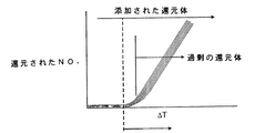
本発明の第二態様は、フィードバックにより還元体添加をリアル−タイムで制御する簡単な手段を提供する。この第二態様では、酸化触媒を、還元体と接触するNOx還元触媒の下流に配置する。この機構は、必要であれば例えば空気の二次的供給により、ガスが酸化触媒上で常にリーンになるように配置される。上記の第一態様と同様に、NOx還元が効果的ではない特定の臨界排ガス温度(図4BのΔT軸に対する破線参照)未満では還元体を添加しないのが望ましい。この温度より上では、還元体量を増加することにより、排ガス中で還元されるNOx量が増加する。実際には、この効果には限界があり、より多くの還元体を導入しても、NOx還元を強化することはできない(図4Aに示す)。従って、望ましい添加率に対応して、僅かに過剰の還元体がNOx還元触媒からすり抜ける区域があり、これより上では、それ以上の還元体が無駄になり、関連する放出物規準に適合しなくなる場合がある。 The second aspect of the present invention provides a simple means of controlling the reductant addition in real time by feedback. In this second embodiment, the oxidation catalyst is disposed downstream of the NO x reduction catalyst that contacts the reductant. This mechanism is arranged so that the gas is always lean on the oxidation catalyst, for example by a secondary supply of air if necessary. As in the first embodiment described above, NO x reduction is desirable not added reductant is less than (see dashed line for ΔT axis in Fig. 4B) a certain critical exhaust gas temperature not effective. The Above temperature, by increasing the reductant amount, NO x amount is reduced in the exhaust gas is increased. In practice, this effect is limited and NO x reduction cannot be enhanced by introducing more reductants (shown in FIG. 4A). Thus, corresponding to the desired addition rate, there is a slight excess of reductant zone slips from the NO x reduction catalyst, above which, more reductant is wasted, it adapted to the relevant emissions standards It may disappear.
全体的なガス組成は、リーンになるように設定されているので、過剰の還元体はすべて下流の酸化触媒上で酸化され、得られる発熱が酸化触媒全体の温度を増加させることができる。酸化触媒への入口温度は、使用中に著しく変化することがあるが、この方法で、我々は、存在する過剰の還元体の尺度であるΔTだけを問題にしている。この制御戦略(図4Bに示す)は、還元体添加率を調節し、測定されるΔTを、最適NOx除去(図4Bにおける暗くした区域)に対応する予め決められた範囲内に維持することに基づいている、すなわち添加率を、ΔTが小さ過ぎる場合は増加し、ΔTが最適な、効率的NOx転化に望まれるよりも大きい場合、減少させる。 Since the overall gas composition is set to be lean, any excess reductant is oxidized on the downstream oxidation catalyst and the resulting exotherm can increase the temperature of the overall oxidation catalyst. Although the inlet temperature to the oxidation catalyst can vary significantly during use, in this way we are concerned only with ΔT, which is a measure of the excess reductant present. This control strategy (shown in FIG. 4B) regulates the reductant addition rate and maintains the measured ΔT within a predetermined range corresponding to optimal NO x removal (darkened area in FIG. 4B). The rate of addition is increased if ΔT is too small and decreased if ΔT is larger than desired for optimal, efficient NO x conversion.
本発明の第二態様の装置実施態様では、車両用リーンバーン内燃機関用の、排ガス中のNOxを好適な還元体でN2に還元するための触媒、還元体の供給源、該NOx還元触媒を該還元体と接触させる手段、該NOx還元触媒の下流に配置された酸化触媒、該酸化触媒を横切る温度差(ΔT)を測定する手段、および使用中に、還元体添加を制御する手段を備えてなる排気機構であって、該還元体添加制御手段が、還元体添加率を制御してΔTを予め決められた範囲内に維持し、該機構が、該酸化触媒上の該排ガス組成がリーンになるように設計されている、機構を提供する。 In the apparatus embodiment of the second aspect of the present invention, a catalyst for reducing NO x in exhaust gas to N 2 with a suitable reductant for a lean burn internal combustion engine for vehicles, a supply source of the reductant, the NO x Means for contacting the reducing catalyst with the reductant; an oxidation catalyst disposed downstream of the NO x reduction catalyst; means for measuring a temperature difference (ΔT) across the oxidation catalyst; and controlling the addition of the reductant during use The reductant addition control means controls the reductant addition rate to maintain ΔT within a predetermined range, and the mechanism is provided on the oxidation catalyst. Provide a mechanism that is designed to make the exhaust gas composition lean.
本発明の第二態様の方法実施態様では、車両用リーンバーン内燃機関の排ガス中にあるNOxをN2に還元するのに好適な触媒への還元体添加をフィードバックにより制御する方法であって、該還元体を酸化するための酸化触媒を該NOx還元触媒の下流に配置すること、該酸化触媒の上流で該排ガス温度を測定すること、該酸化触媒の下流で該排ガス温度を測定すること、該入口および出口温度の差(ΔT)を決定すること、およびΔTが予め決められた範囲内に入るように、還元体添加の率を調節することを含んでなる方法を提供する。 In a method embodiment of the second aspect of the present invention, there is provided a method for controlling the addition of a reductant to a catalyst suitable for reducing NO x in exhaust gas of a lean burn internal combustion engine for a vehicle to N 2 by feedback. Disposing an oxidation catalyst for oxidizing the reductant downstream of the NO x reduction catalyst, measuring the exhaust gas temperature upstream of the oxidation catalyst, and measuring the exhaust gas temperature downstream of the oxidation catalyst Determining a difference between the inlet and outlet temperatures (ΔT) and adjusting the rate of reductant addition such that ΔT falls within a predetermined range.
NOx−トラップを包含する機構に本第二態様を適用する際の問題の一つは、NOx−トラップを再生するためにリッチ(すなわちラムダ<1)排ガスを使用しなければならない場合があることである。我々は、二次的な空気注入を必要とせずに、本発明の第二態様をそのようなNOx−トラップに拡張できるようにするための3種類の実施態様を提案する。 NO x - One mechanism involves a trap to the present in applying a second aspect issues, NO x - sometimes rich to play a trap (i.e. lambda <1) must use the exhaust gas That is. We propose three embodiments to allow the second aspect of the invention to be extended to such NO x -traps without the need for secondary air injection.
図5に示す第一実施態様では、少なくとも2個のNOx−トラップを平行に配置し、それぞれに還元体注入装置を接続する。各NOx−トラップ上のガス毎時空間速度(GHSV)は、各ライン中の相対的背圧によって異なるが、通常、配置がそれぞれ等しくなるように、この場合、GHSVが各ラインで実質的に等しくなるように、機構を設定する。NOx−トラップ再生は、機構中のNOx−トラップで直列で行う、すなわち、いずれの場合も、機構中の全NOx−トラップから出る排ガスを混合した時に、その組成がリーン、すなわちラムダ>1、になるように、少なくとも一ラインは還元体を注入しない。混合された排ガスは、上記本発明の第二態様の酸化触媒に送られる。 In the first embodiment shown in FIG. 5, at least two NO x -traps are arranged in parallel, and a reductant injection device is connected to each. Each NO x - gas hourly space velocity over the trap (GHSV) varies depending on the relative backpressure in each line, usually so arranged are equal respectively, in this case, substantially equal in GHSV each line Set the mechanism to be. NO x -trap regeneration is performed in series with NO x -traps in the mechanism, ie, in any case, when exhaust gases from all NO x -traps in the mechanism are mixed, the composition is lean, ie lambda> 1, at least one line does not inject the reductant. The mixed exhaust gas is sent to the oxidation catalyst of the second aspect of the present invention.
図6Aおよび6Bに示す第二実施態様では、NOx−トラップを単一の基材モノリス上に被覆し、少なくとも2個の注入装置を基材モノリスの上流側に配置し、注入された還元体がモノリス基材の特定区域に向けられるように配置する。 In a second embodiment shown in FIGS. 6A and 6B, a NO x -trap is coated on a single substrate monolith and at least two injectors are located upstream of the substrate monolith, and the injected reductant Is oriented to a specific area of the monolith substrate.
この実施態様の利点は、第一実施態様および平行NOx−トラップを使用する他の機構と比較して、機構を収容するための、車両上に必要とする空間が少なくて済むことである。 The advantage of this embodiment, the first embodiment and the parallel NO x - compared to other mechanisms that use a trap, for housing the mechanism is that less space is required on the vehicle.
第三の実施態様は、第二実施態様と類似しており、図7および8に示す。この実施態様は、上流の3方フラップバルブおよびフラップバルブの両側に位置する還元体注入装置を備えてなる。NOx−トラップ「充填」の際、フラップバルブを、排ガス流の方向と平行になるように整列させることができる。再生の際、フラップバルブを、NOx−トラップの還元体を受け取っている側の上に倒し、それによって排ガス流の一部を、再生されているNOx−トラップから離れるように向け、その中を通る排ガスの流れを少なくする。 The third embodiment is similar to the second embodiment and is shown in FIGS. This embodiment comprises an upstream three-way flap valve and a reductant injection device located on both sides of the flap valve. During NO x -trap “filling”, the flap valves can be aligned to be parallel to the direction of the exhaust gas flow. During regeneration, the flap valve is tilted over the NO x -trap reductant receiving side, thereby directing a portion of the exhaust gas stream away from the regenerated NO x -trap, Reduce the flow of exhaust gas through
この実施態様の利点は、NOx−トラップの、再生すべき部分にある排ガス流が少なくなり、放出されるNOxの還元が促進されるので、第二実施態様よりも再生がより効率的に行われる、すなわち必要とされる還元体が少なくなる。さらに、我々は、第二および第三の実施態様は、それ自体が特許権を受けられるように新規であり、発明であると考えている。 The advantage of this embodiment, NO x - trap, the less the exhaust gas flow in the portions to be reproduced, since the reduction is promoted emitted NO x, reproducing more efficiently than the second embodiment Less reductant is performed, ie, required. Furthermore, we believe that the second and third embodiments are novel and invented so that they are patentable in themselves.
従って、第三の態様により、本発明は、車両用リーンバーン内燃機関用の排気機構であって、単一のモノリス基材上に配置されたNOx−トラップ(該基材の上流末端は、流体の流れ方向で少なくとも2つの区域に小分割されている)、および該少なくとも2つの区域の画分を還元体と順次接触させる手段を備えてなり、該NOx−トラップは、全体として排ガス流に対してイン−ラインのままである、排気機構を提供する。 Therefore, according to a third aspect, the present invention provides an exhaust mechanism for a lean burn internal combustion engine for a vehicle, wherein the NO x -trap (upstream end of the substrate is disposed on a single monolith substrate) And at least two sections in the flow direction of the fluid), and means for sequentially contacting the fraction of the at least two sections with the reductant, the NO x -trap as a whole An exhaust mechanism that remains in-line.
一実施態様で、NOx−トラップを還元体と接触させる手段は、還元体の液滴がNOx−トラップと接触するように、基材の上流末端に十分に近い所に配置された注入装置を備えてなる。還元体をNOx−トラップ上流の排ガス中に注入する意図は、排ガスの酸素濃度を下げること、すなわち濃縮することにあるが、排ガス組成をリッチ(ラムダ<1)にする必要はない。先行技術の配置では、還元体をNOx−トラップのはるか上流に、例えば一個以上のエンジンシリンダーの排気行程中に導入するか、またはヨーロッパ特許第0758713A号明細書(ここに参考として含める)の場合では、例えば還元体を、NOx−トラップの上流に配置された酸化触媒およびディーゼル粒子状物質フィルターの上流で排気導管中に注入する。どちらの場合も、液体還元体の滴が蒸発する。さらに、最大ガス流では、ある程度のリッチ状態が得られる前に、単に過剰の酸素をすべて除去する(燃焼により)ためにだけ大量の還元体が必要になる。還元体が炭化水素燃料、例えばディーゼル、である場合、この方式は燃費が悪い。 In one embodiment, NO x - means for contacting the reduced form traps, droplets of reductant NO x - into contact with the trap, the injection device arranged at sufficiently close to the upstream end of the substrate It is equipped with. The intention of injecting the reductant into the exhaust gas upstream of the NO x -trap is to lower the oxygen concentration of the exhaust gas, that is, to concentrate it, but it is not necessary to make the exhaust gas composition rich (lambda <1). In the prior art arrangement, the reductant is introduced far upstream of the NO x -trap, for example during the exhaust stroke of one or more engine cylinders, or in the case of EP 0 758 713 A (herein incorporated by reference) Then, for example, the reductant is injected into the exhaust conduit upstream of the oxidation catalyst and diesel particulate filter located upstream of the NO x -trap. In either case, the liquid reductant drops evaporate. Furthermore, the maximum gas flow requires a large amount of reductant simply to remove all excess oxygen (by combustion) before a certain rich state is obtained. If the reductant is a hydrocarbon fuel, such as diesel, this scheme has poor fuel economy.
我々は、大きさを制御した燃料滴をNOx−トラップ触媒の上流面の近くに導入し、注入された燃料の蒸発を計画的に制限することにより、燃料の液滴を触媒表面に衝突させることができることを見出した。これが起これば、その環境は強い還元性になり、近くに貯蔵されていた硝酸塩を還元することができる。従って、この配置は、NOx−トラップ再生に伴う燃料損失を大幅に軽減できる。 We introduce fuel droplets of a controlled size near the upstream surface of the NO x -trap catalyst and systematically limit the evaporation of the injected fuel to impinge the fuel droplets on the catalyst surface. I found that I can do it. If this happens, the environment becomes highly reducible and nitrates stored nearby can be reduced. Therefore, this arrangement can greatly reduce the fuel loss associated with NO x -trap regeneration.
粒子動力学により、液体還元体の滴は、従来のフロースルーセラミックまたは金属モノリス基材を、その壁上に担持されたNOx吸収材上に衝突することなく、通過する場合がある。還元体がNOx吸収材と接触する可能性を増加するために、一実施態様では、セラミックまたは金属フォームを含んでなるフォーム基材を使用する。別の実施態様は、ヨーロッパ特許第EP−A−1057519号明細書または国際特許第WO03/038248号明細書(どちらもここに参考として含める)に記載されているような、内部じゃま板を包含する金属製部分フィルター基材を使用する。別の実施態様では、NOx−トラップは従来のセラミックウォール−フロ−フィルターを含んでなり、そこでは、圧損により動かされる対流(convention)が、燃料滴を確実に、貯蔵されているNOxに接触させる筈である。この後者の実施態様では、粒子状物質(PM)自体の効果的な濾過は重要ではないので、多孔質フィルターを使用できようが、日本国特許第JP−B−2722987号明細書(JP−A−06159037)(ここに参考として含める)に記載されているようにNOxとPMを組み合わせた抑制、すなわちフィルターが煤燃焼触媒/NO酸化触媒、例えばPt、NOx吸収材、例えば酸化バリウム、および所望によりNOx還元触媒、例えばロジウム、を包含するのが望ましいであろう。 Due to particle dynamics, liquid reductant droplets may pass through a conventional flow-through ceramic or metal monolith substrate without impinging on the NO x absorbent supported on its walls. In order to increase the likelihood that the reductant will come into contact with the NO x absorbent, in one embodiment, a foam substrate comprising a ceramic or metal foam is used. Another embodiment includes an internal baffle as described in European Patent No. EP-A-1057519 or International Patent No. WO 03/038248, both of which are hereby incorporated by reference. A metal partial filter substrate is used. In another embodiment, the NO x -trap comprises a conventional ceramic wall-flow filter, where convection driven by pressure drop ensures that fuel drops are stored in the stored NO x . It should be touched. In this latter embodiment, effective filtration of the particulate matter (PM) itself is not important, so a porous filter could be used, but Japanese Patent No. JP-B-2722987 (JP-A -06159037) (suppression that combines NO x and PM as described herein incorporated by reference), i.e. the filter soot combustion catalyst / NO oxidation catalyst, for example Pt, NO x absorbent, for example barium oxide, and optionally the NO x reduction catalyst, such as rhodium, it may be desirable to include.
還元体注入装置とNOx−トラップとの間に配置された従来のフロースルーモノリス上に酸化触媒を被覆することも、粒子動力学にとって有利になる場合がある。モノリスの開いた前方面積およびセル密度に応じて、燃料滴が実質的に酸化せずに酸化触媒を通過し、NOx−トラップ中に貯蔵されたNOxを還元するのに利用できる。対照的に、蒸発した炭化水素還元体は酸化触媒上で、より酸化され易い。 It may also be advantageous for particle kinetics to coat the oxidation catalyst on a conventional flow-through monolith placed between the reductant injector and the NO x -trap. Depending on the forward area and cell density was open monolith, the fuel droplets pass through the oxidation catalyst without substantially oxidizing, NO x - can be used to reduce the stored NO x in the trap. In contrast, the evaporated hydrocarbon reductant is more likely to be oxidized on the oxidation catalyst.
別の実施態様では、NOx−トラップ画分を還元体と接触させる手段が、基材の上流末端上に配置されたフラップバルブを備えてなり、それによって基材を少なくとも二つの区域に小分割する。一つの配置では、注入装置が各区域に接続される。 In another embodiment, the means for contacting the NO x -trap fraction with the reductant comprises a flap valve disposed on the upstream end of the substrate, thereby subdividing the substrate into at least two zones. To do. In one arrangement, an infusion device is connected to each area.
第三態様の方法では、車両用リーンバーン内燃機関の排気機構中にあるモノリス基材上に配置されたNOx−トラップが、NOx−トラップの画分を還元体と接触させることにより、再生され、NOx−トラップ全体は排ガス流に対してイン−ラインのままである。 In the method according to the third aspect, the NO x -trap disposed on the monolith substrate in the exhaust mechanism of the lean burn internal combustion engine for a vehicle makes the NO x -trap fraction come into contact with the reductant to regenerate. And the entire NO x -trap remains in-line to the exhaust gas stream.
一実施態様では、還元体がNOx−トラップの画分と、排ガス流が減少した時に接触する。 In one embodiment, the reductant is NO x - and fractions trap, contact when the exhaust gas flow is reduced.
本発明の第四の態様では、車両用リーンバーン内燃機関用の、NOx還元触媒、該触媒の上流に配置された還元体注入装置、および使用時に、還元体添加を制御する手段を備えてなる排気機構であって、還元体添加制御装置が、デューティサイクル中の全車両速度において、車両の平均デューティサイクル速度で所望のNOx転化に相関するように予め決められた率で、還元体を触媒に供給する排気機構を提供する。 In a fourth aspect of the present invention, for lean-burn internal combustion engine for a vehicle, NO x reduction catalyst, reductant injection device disposed upstream of the catalyst, and in use, means for controlling the reductant adding a composed exhaust mechanism, the reductant addition control device, the entire vehicle speed during the duty cycle, at a predetermined rate to correlate the desired of the NO x conversion at an average duty cycle speed of the vehicle, the reductant An exhaust mechanism for supplying to a catalyst is provided.
第四態様の発明は、デューティサイクルが限られた車両、例えばまたは廃棄物トラック、用の後付け製品市場に特に用途がある。その考え方は、平均デューティサイクル速度において、NOx還元触媒中で特定量のNOx、例えば90%、を還元するのに、どのような還元体注入率が必要であるかを決定することである。例えば、NOx還元触媒がNOx−トラップを含んでなる場合、使用中に、連続的な速度および量のHC燃料注入、例えば毎分2秒間の注入、を行うための機構制御装置を配置することができる。この機構制御装置は、確実にNOx−トラップが実質的に完全に再生されるための比較的長いリッチHC燃料パルスを時々与え、続いてNOx−トラップの貯蔵能力を維持するために、短い濃縮パルスの連続をより頻繁に与えるように設定することもできる。注入戦略のより正確な詳細は、車両およびそのデューティサイクルによって異なる。 The invention of the fourth aspect has particular application in the retrofit market for vehicles with limited duty cycles, such as waste trucks. The idea is to determine what reductant injection rate is required to reduce a certain amount of NO x , for example 90%, in the NO x reduction catalyst at an average duty cycle speed. . For example, if the NO x reduction catalyst comprises a NO x -trap, a mechanism controller is provided for performing continuous rate and volume HC fuel injection, eg, 2 seconds of injection per minute, during use. be able to. This mechanism controller is short to ensure that the NO x -trap is given a relatively long rich HC fuel pulse from time to time to be substantially completely regenerated, and subsequently to maintain the storage capacity of the NO x -trap. It can also be set to give a series of enrichment pulses more frequently. The more precise details of the injection strategy will depend on the vehicle and its duty cycle.
平均デューティサイクル速度よりも高い速度では、NOxがより多くなり、空気流量が大きくなり、従って、不十分な還元体のために全体的なNOx転化率は低下するが、高速度は、例えば市中心部のバスではあまり起こりそうもないので、そのような高速度におけるNOx転化による燃料損失は、先行技術の、例えば注入タイミングを遅らせた設定と比較して、全走行サイクルにわたって少ないであろう。HC注入率と平均デューティサイクル速度の相関性は、特定の用途に合わせることができる、例えばマンチェスター(英国)市中心部におけるバスは、ロンドン(英国)におけるバスとは異なったデューティサイクルに直面すると予想されるであろう。 At speeds higher than the average duty cycle speed, there will be more NO x and higher air flow and therefore lower overall NO x conversion due to insufficient reductant, but high speed will be since no less likely is the bus of the city center, the fuel loss due to nO x conversion in such high speeds, the prior art, as compared to example delayed injection timing setting, der less over the entire driving cycle Let's go. The correlation between HC injection rate and average duty cycle speed can be tailored to a specific application, eg buses in Manchester (UK) city center are expected to face a different duty cycle than buses in London (UK) Will be done.
第四態様の一実施態様では、酸化触媒を還元体注入装置とNOx−トラップの間に配置し、NOx−トラップの再生温度を増加し、排ガスから酸素を除去し、NOx−トラップ再生のためのリッチ排ガスを確保する。 In one embodiment of the fourth aspect, an oxidation catalyst is disposed between the reductant injection device and the NO x -trap, the regeneration temperature of the NO x -trap is increased, oxygen is removed from the exhaust gas, and the NO x -trap regeneration is performed. Ensure rich exhaust gas for.
第四の態様による車両用内燃機関の排ガス中NOxの還元方法は、デューティサイクル中の全車両速度で、平均デューティサイクル速度における所望のNOx転化率に相関する率で還元体を排ガス中に導入すること、およびNOxおよび還元体を含む排ガスをNOx還元触媒と接触させることを含んでなる。 Method for reducing exhaust gas NO x in an internal combustion engine for a vehicle according to the fourth aspect, in all vehicle speeds in a duty cycle, a reductant into exhaust gas at a rate correlated to the desired of the NO x conversion in the average duty cycle speed Introducing and contacting an exhaust gas comprising NO x and a reductant with a NO x reduction catalyst.
特別な配置では、NOx還元触媒およびここに記載する還元体送達機構を、上記ヨーロッパ特許第EP−B−0341832号明細書に記載されている配置の下流に配置する。 In a special arrangement, the NO x reduction catalyst and the reductant delivery mechanism described herein are arranged downstream of the arrangement described in the above-mentioned European patent EP-B-0341832.
他の記載がない限り、本発明で使用する触媒は、金属またはセラミックまたは炭化ケイ素、例えばコージーライト、材料から製造された高表面積基材モノリス上に塗布する。一般的な配置は、100〜600セル/平方インチ(cpsi)、例えば300〜400cpsi(15.5〜93.0セルcm−2、例えば46.5〜62.0セルcm−2)のハニカム、フロースルーモノリス構造である。 Unless otherwise stated, the catalyst used in the present invention is coated on a high surface area substrate monolith made from metal or ceramic or silicon carbide, eg cordierite, material. A typical arrangement is a honeycomb of 100-600 cells / in 2 (cpsi), for example 300-400 cpsi (15.5-93.0 cell cm −2 , for example 46.5-62.0 cell cm −2 ), It is a flow-through monolith structure.
内燃機関は、ディーゼルまたはリーンバーンガソリンエンジン、例えばガソリン直噴エンジン、でよい。ディーゼルエンジンは、関連する法規に規定されている軽負荷エンジンまたは重負荷エンジンでよい。 The internal combustion engine may be a diesel or lean burn gasoline engine, such as a gasoline direct injection engine. The diesel engine may be a light load engine or a heavy load engine as defined by relevant legislation.
本発明をより深く理解するために、その実施態様を、添付の図面を参照しながら説明する。 For a better understanding of the present invention, embodiments thereof will be described with reference to the accompanying drawings.
全体的に番号10で示す本発明の第一態様による機構を図1に示すが、そこでは12がディーゼルエンジンを、14が排気マニホルドを、16が排気ラインを、18がNOx還元触媒、例えば5重量%Cu/ベータゼオライトリーン−NOx触媒を表す。還元体供給手段20は、触媒18の上流で排気ライン16中に、ある量のディーゼル燃料を注入するための注入装置を包含する。熱電対TC1は、触媒18への入口で排ガスの温度を検出し、検出した温度をエンジン管理装置(ECU)(図には示していない)中のプロセッサーに伝達する。
The mechanism according to the first aspect of the overall present invention shown by the numeral 10 is shown in FIG. 1, the 12 diesel engines there, the 14
エンジンに対する負荷が増加するにつれて、排ガス中のNOxレベルがほぼ直線的な様式で増加する。同様に、排ガス温度も負荷と共に増加する。特定の臨界温度未満では、温度が完全なNOx除去反応が起こるには低過ぎるので、還元体を添加しない。図2Aおよび2Bは、特定エンジン12のデューティサイクル全体にわたる、エンジン負荷に対する排ガスNOx濃度およびエンジン負荷に対する温度の相関性を示す。実際には、様々な排ガス温度で添加される還元体の実際量は、特定のデューティサイクルの性質によって異なるが、高温でより大量のNOxを除去するには、より多くの還元体を必要とするという傾向がある。そのような決定は、当業者には公知の適切な装置および技術を使用して、例えば好適なエンジンダイナモメータおよびNOxセンサーを使用して、行うことができる。これらの測定から、走行サイクル全体にわたって排ガス中のNOxを触媒上でN2に還元するのに必要な還元体添加の率を計算すること、および図2Cに示すようにこれを排ガス温度に相関させることが可能である。これらの相関関係を、図1のシステムを動かしているそのような全車両のECUプロセッサーに搭載し、ルックアップテーブルとして保存することができる。使用の際、還元体添加の率および量を、熱電対TC1により検出する排ガスの温度と比例するように、ECUにより制御する。このように還元体を添加することにより、車両上でNOx還元を効率的に、簡単に制御することができる。
As the load on the engine is increased, NO x levels in the exhaust gas is increased in approximately linear fashion. Similarly, the exhaust gas temperature increases with load. Below a certain critical temperature, the reductant is not added because the temperature is too low for a complete NO x removal reaction to occur. FIGS. 2A and 2B show the correlation of exhaust gas NO x concentration versus engine load and temperature versus engine load over the duty cycle of a
図3に全体的に30で示す、本発明の第二態様の一実施態様による機構は、図1と同じ番号で示す同様の特徴を有する。図3に示す、図1の機構に追加する新規な特徴は、酸化触媒32、例えばガンマ−アルミナウォッシュコート上に担持された白金1重量%、を包含し、TC1が、NOx還元触媒18の下流で、触媒18と酸化触媒32の間に配置され、第二の熱電対TC2が酸化触媒32の下流に配置されていることである。
The mechanism according to one embodiment of the second aspect of the present invention, indicated generally at 30, in FIG. 3, has similar features indicated by the same numbers as in FIG. The novel features shown in FIG. 3 and added to the mechanism of FIG. 1 include an
使用の際、この機構は、ガスが確実に酸化触媒32上で常にリーンになるように操作する。図1の機構と同様に、NOx還元触媒が、その、NOx還元に触媒作用するための低温活性温度未満にある、特定の臨界排ガス温度未満では、還元体は添加されない。この温度を超えると、還元体の量を増加することにより、排ガス中で還元されるNOx量が増加する。僅かに過剰のすり抜けた還元体が酸化触媒32上で酸化され、その結果、生じる発熱により、TC2とTC1で検出された温度の差、すなわちΔT=TC2−TC1、として測定される、触媒を横切る温度増加を引き起こす。この制御戦略は、測定されるΔTが、最適NOx除去に対応する予め決められた値に実質的に維持されるように、還元体添加率を調節することである。還元体流は、ΔTが小さ過ぎる場合に増加し、ΔTが最も効率的なNOx転化に望ましい値より大きい場合に減少させる。
In use, this mechanism operates to ensure that the gas is always lean on the
図5に全体的に40で表す、本発明の第二態様の第二実施態様による機構では、図3と同様の特徴を同じ参照番号で示す。図5に示す、図3の機構に追加する新規な特徴は、平行な排気ライン44で配置された複数のNOx−トラップ42を包含し、各ラインは独自の還元体供給手段20を有することである。
In the mechanism according to the second embodiment of the second aspect of the present invention, indicated generally at 40 in FIG. 5, the same features as in FIG. The novel features shown in FIG. 5 and added to the mechanism of FIG. 3 include a plurality of NO x -
この、図3に示す、本発明の第二態様の配置は、リーン条件下で作動するリーンNOx触媒またはアンモニアSCR機構に応用した時に特に問題を生じないが、NOx−トラップ42の再生がより問題となる。リッチNOx−トラップ再生の必要性から生じる問題の一つは、下流の酸化触媒32が、酸素不足の際に過剰の還元体を除去できないことである。これは、テールパイプにおける高度の還元体放出、および他の起こり得る問題につながる。
The arrangement of the second aspect of the present invention shown in FIG. 3 does not cause any particular problem when applied to a lean NO x catalyst or an ammonia SCR mechanism that operates under lean conditions, but the regeneration of the NO x -
図5の機構は、排ガス流を、それぞれ独自のNOx−トラップ42および還元体注入装置20を備えた2本以上の平行ライン44にどのように分割できるかを示す。どの時点においても、少なくとも一本のラインは還元体が注入されていないので、NOx−トラップ42から出るガス流をすべて混合すると、得られるガスは、下流の酸化触媒32の上を通過する前は、全体的にリーンである。このようにして、過剰の還元体はすべて酸化され、得られるΔTは、図3の実施態様に関して上に記載するように、NOx還元機構に使用することができる。
The mechanism of FIG. 5 shows how the exhaust gas stream can be divided into two or more
本発明の第二態様の第三実施態様を図6Aおよび6Bに示すが、そこでは図5に示す実施態様の複数の平行NOx−トラップ42が、単一のNOx−トラップ42AおよびNOx−トラップの上流末端で等間隔に配置された3個の還元体供給手段20によって置き換えられ、還元体スプレーを、基材モノリスの前面にある並列した区域45に向けており、その中心は注入点46により限定される。この配置は、図5に示す第一実施態様と同じ全体的な効果を与えるが、2個以上の還元体注入装置を備えた、より大きな単一の、すなわち一体的なNOx−トラップを使用している。これらの注入装置は、逐次的な様式で操作されるので、どの時点でも、NOx−トラップの一部だけが再生を受け、この部分から出るガスは、再生されていない部分から出る排ガスと混合され、全体的にリーンのガス流を触媒32上での酸化に供給する。
A third embodiment of the second aspect of the invention is shown in FIGS. 6A and 6B, where a plurality of parallel NO x -
この実施態様に対する還元体供給手段は、燃料の液滴が触媒表面に衝突するように、制御された大きさの滴を触媒前面の近くに与えるように設定される。これが起これば、環境は強い還元性になり、近くに貯蔵されていた硝酸塩を還元することができる。この配置の利点は、NOx−トラップ再生のための燃料損失が、エンジンの一個以上のシリンダーで注入タイミングを調節する機構よりも少ないことである。 The reductant supply means for this embodiment is set to provide controlled sized drops close to the front of the catalyst so that the fuel drops strike the catalyst surface. If this happens, the environment becomes highly reducible and nitrates stored nearby can be reduced. The advantage of this arrangement is that there is less fuel loss for NO x -trap regeneration than a mechanism that adjusts injection timing in one or more cylinders of the engine.
図7に関して、排ガス後処理機構80は、煤燃焼反応器120を備えてなり、その入口は、ディーゼルエンジン(図には示していない)の排気マニホルドに接続されている。反応器120は、その上流部分に、アルミナ系ウォッシュコートおよびPtを担持するセラミックハニカムからなる酸化触媒122を含む。反応器120は、その下流部分に、フィルター等級セラミックハニカムからなるウォール−フロ−フィルター124を含み、その通路は、入口末端と出口末端で交互に閉鎖および開放されており、入口末端で閉鎖されている通路は、出口末端では開放されており、入口末端で開放されている通路は、出口末端では閉鎖されている。そのような配置は、ヨーロッパ特許第EP−B−0341832号明細書に記載されており、その配置はCRT(商品名)と呼ばれている。反応器120の出口末端から、NOx−トラップ容器130の入口にあるフラップバルブ128X、Y、Zの操作チャンバーとして、プレナム126が続いている。容器130は、酸化バリウムおよび金属PtおよびRhを含むアルミナウォッシュコートを担持するフロースルーセラミックハニカムモノリス基材からなるNOx−トラップ131X、Yを含む。フラップバルブ128X、Y、Zの支点は、仕切り129の上に取り付けてあり、その仕切りは、反応器130の面を直径方向に横切って伸び、NOx−トラップ131の面に対してガスを通さない用に密封されている。反応器130の各区域X、Yは、バルブ128の両側に、反応物注入装置132X、Yを備えている。図に示すような完全な反応器130では、バルブ128は中央位置Zにある。バルブ位置XおよびYは、一方の側への流入位置(inset)として示す。反応器130には、大気中またはその後の処理につながる出口134が形成されている。好ましくは、反応器130の2個の半部分中への流量は、最終的にリーンの組成物を与えるように制御され、その混合物は、図3または5に示す配置で酸化触媒上に送られる。
With reference to FIG. 7, the exhaust
この機構の正常な運転では、蒸気(H2O(g))、二窒素(N2)、酸素(O2)、二酸化炭素(CO2)、未燃焼炭化水素燃料(HC)、一酸化炭素(CO)、窒素酸化物(NOx)および粒子状物質(PM)を含んでなる排ガスが、例えば300℃で、触媒122と接触し、その上でNOがNO2に酸化され、HCおよびCOの一部が蒸気およびCO2に酸化される。次いで、排ガスは、フィルター124に入り、その上でPMの大部分が集められ、触媒122中で形成されたNO2および場合によりO2との反応により燃焼する。次いで、PMが除去されたガスは、3通りの様式、すなわち128Zでは、NOx−トラップ区域130Xおよび130Yの両方がNOxを吸収(または吸着)し、128Xでは、区域131Xが、プレナム126を離れるガスの小画分および132Xでディーゼル燃料の注入を受ける。区域131Xは再生を受け、その流出物は区域130Yの流出物と再び混合され、区域131Yは、ガスの主要部分を受け、NOxを吸収し、その流出物を134で大気中に放出し、128Yでは、区域131Yが、128Xで記載した役目を行う。
In normal operation of this mechanism, steam (H 2 O (g) ), dinitrogen (N 2 ), oxygen (O 2 ), carbon dioxide (CO 2 ), unburned hydrocarbon fuel (HC), carbon monoxide Exhaust gas comprising (CO), nitrogen oxides (NO x ) and particulate matter (PM) is contacted with the
NOx−トラップ131YがNOxを吸収するための空き容量を有している時に、エンジン管理装置(図には示していない)が、区域Xから区域Yに切り換え、その逆も行う。
When the NO x -
図8に関して、図7に示す機構とは別の機構を全体的に番号90で示し、図7と共通の特徴は同じ番号で示すが、ここでは反応器120が触媒122だけを含む。ここでは番号125のPMフィルター容器は、別の容器121の中にある。この容器は、フィルターを通る流れの方向を反転させる点で異なっている。反応器120の出口は、位置123Aと123B(流入)で操作できる4方バルブ123によりフィルター容器121に接続され、フィルター125を通してそれぞれ右側から左側へ、および左側から右側への流れを与えることができるが、中間点はフィルター125をバイパスさせるので、閉塞させる中間点は無い。バルブ123の操作は、非常に急速になるように制御する。フィルター125をどちらかの方向に離れることにより、ガスはバルブ123AまたはBを通って、構造的および機能的に図7と同等であるNOx−トラップ130に流れる。
With respect to FIG. 8, a mechanism different from that shown in FIG. 7 is indicated generally by the numeral 90 and features common to FIG. 7 are indicated by the same numerals, but here the
最新型ディーゼルエンジンの特徴は、エンジンから出るNOxおよび/または排ガスの温度が、ヨーロッパ特許第EP−B−0341832号明細書に記載されているようにNOの酸化により触媒作用で発生したNO2を使用する受動的フィルター再生には低過ぎる場合があることである。この問題に対する解決策の一つは、排気機構中の温度を増加することによりPMをフィルター上で燃焼させ、フィルターを横切る背圧を妥当な設計公差内に維持し、能動的にフィルターを再生することである。そのような能動的再生技術は、例えばヨーロッパ特許第0758713A号明細書に記載されている。 A feature of modern diesel engines is that the NO x and / or exhaust gas temperature leaving the engine is generated by NO 2 catalyzed by oxidation of NO as described in EP-B-0341832. May be too low for passive filter regeneration using. One solution to this problem is to burn the PM on the filter by increasing the temperature in the exhaust system, maintain the back pressure across the filter within reasonable design tolerances, and actively regenerate the filter. That is. Such an active regeneration technique is described, for example, in EP 0 758 713 A.
図8に開示する機構の、CRT(商品名)プロセスの実際的用途に対する優位性は、フィルター中の流れ反転を使用し、走行サイクル全体にわたってNO2中で容易に燃焼されないPMを除去できることにある。未燃焼PMは、第二の使い捨てフィルター上に集め、適当な間隔で除去することができる。従って、この配置は、特に後付け製品市場において、高価で、燃費のかかる能動的再生装置を取り付ける代わりに、実用的で経済的な解決策を提供する。 The advantage of the mechanism disclosed in FIG. 8 over the practical use of the CRT (trade name) process is that it can use flow reversal in the filter to remove PM that is not easily burned in NO 2 throughout the run cycle. . Unburned PM can be collected on a second disposable filter and removed at appropriate intervals. Thus, this arrangement provides a practical and economical solution instead of installing expensive and fuel-efficient active regenerators, especially in the retrofit market.
図8に示す実施態様でガス流の方向を切り換えるには、図9Aおよび9Bに示す好適な4方バルブ123を使用することができる。これらの図面に示す平面図は、実質的に円筒形のバルブケーシング100に関し、そのケーシングは、内部に直径が大きい周辺部区域102が形成され、回転シャフト106を有する長方形バタフライデフレクタ104の横行範囲を限定しており、その回転シャフトは、バルブケーシングの外に、シールを経由してアクチュエータ(図には示していない)に伸びている。横行範囲の極限は、直径が異なる区域間の段差108により限定され、そのような段差は、その意図する通路からのガス漏れを制限する。「LHS」は「左側」を、RHSは「右側」を意味する。
To switch the direction of gas flow in the embodiment shown in FIG. 8, a suitable four-
図7、8および9に示す配置は、少なくとも下記の理由から独立して発明になると考えられる。機構内バルブ使用は、複雑な配管を避けるために望ましいことが分かっているが、その採用は、比較的高温の排ガス中ではバルブ機構が腐食し易く、バルブの耐用寿命前に交換することになるために、限られている。この問題は、重負荷ディーゼル車両に特に関連する。しかし、本配置では、ガスはディーゼル排気であり、これは、特に最新のエンジンでは先行技術のエンジン程高温ではなく、排ガスは、低硫黄ディーゼルを使用するためにSOx分が低く、フィルター下流のガスに含まれる、バルブを損なう可能性があるPMは比較的少量であり、ガスはリーンであり、従って、鋼を不動態化する。そのため、これらの特徴を組み合わせることにより、機構中のバルブ使用は実用的な提案になる。 The arrangements shown in FIGS. 7, 8 and 9 are considered to be inventions independently for at least the following reasons. In-mechanism valve use has proven to be desirable to avoid complex piping, but its adoption is likely to corrode the valve mechanism in relatively hot exhaust gases and should be replaced before the useful life of the valve. In order to be limited. This problem is particularly relevant for heavy duty diesel vehicles. However, in this arrangement, the gas is diesel exhaust, which is not as hot as the prior art engine, especially in modern engines, and the exhaust gas has a low SO x content due to the use of low sulfur diesel, downstream of the filter. The gas contains a relatively small amount of PM that can damage the valve, the gas is lean, and thus passivates the steel. Therefore, by combining these features, the use of a valve in the mechanism becomes a practical proposal.
図10に示す機構50で、52は条件付きシステム制御装置(CSC)であり、54はマスタースイッチであり、56は同期発電機であり、58はブロックコンデンサーであり、60は熱電対であり、62は注入制御装置(ICU)であり、64は燃料ポンプであり、66はバルブであり、68は燃料注入装置であり、70は正の電力線である。CSC52は、マスタースイッチ54をオンにし、DCブロックコンデンサー58の後にある同期発電機56からのACリプルにより決定されるようにエンジンが作動しており、排気機構を検出するために適当に配置された熱電対60の出力が、好適なNOx−トラップ上のNOx還元用に予め決められた最低温度を超えていれば、電力をICU62に供給するスイッチである。マスタースイッチ54は、キー−オン位置に接続する必要はない。
In the
CSC52は、3つの特徴(マスタースイッチ位置、同期発電機リプルの検出および予め決められた最小値を超える排ガス温度)のすべてが一致すれば、連続速度および量のHCを発生するように設計されている。CSC52がオンになると、注入ポンプ64およびICU62に電力が供給され、ICU62がソレノイドバルブ66を操作し、排ガスがNOx吸収成分の上流にある酸化触媒上を通過する前に排ガスを濃縮する一連のパルスを発生する。典型的には、注入制御装置は、比較的非常に長いリッチパルスを時々発生し、確実にNOx−トラップを実質的に完全に空にし、その後でより頻繁な一連の短い濃縮パルス、例えば毎分2秒間の注入、を発生し、NOx−トラップの貯蔵能力を維持する(図11参照)。
The
この燃料注入率は、選択したNOx転化、例えば平均デューティサイクル速度で90%、に相関している。平均デューティサイクル速度よりも高い速度では、より多くのNOxおよび大量の空気流があり、従って、NOx転化は低下するであろう。しかし、高速度は、例えば市中心部のバスまたは廃棄物トラックでは、あまり起こりそうもなく、そのような高速度により引き起こされるNOx転化による燃料損失の増加は、先行技術の配置、例えば遅延注入タイミングを使用する先行技術の配置と比較して、走行サイクル全体にわたって少ない。 This fuel injection rate is correlated to the selected NO x conversion, eg, 90% at average duty cycle speed. At speeds higher than the average duty cycle speed, there will be more NO x and a large amount of air flow and therefore NO x conversion will be reduced. However, high speed, for example in a bus or waste track the city center, very likely also without the increase in fuel loss due to NO x conversion caused by such high speeds, the prior art arrangement, for example, the delay injection Compared to prior art arrangements that use timing, there is less throughout the driving cycle.
非常に一般的に、NOx−トラップ再生を何時行うべきかを予見するための簡単な制御機構を、特に後付けする用途で提供するために、ここに記載するNOx−トラップを使用する機構を開発したが、多くの車両は、車両運転の他の特徴を制御するためのデータをECUに入力する一連のセンサーをすでに包含している。ECUを適切に再プログラム化することにより、そのような既存のセンサー入力の一つ以上を、残留NOx−トラップ容量を予見する目的に使用することができる。これら入力には、好適な時計手段の状態を感知することにより、予め決められた、または予見される、キー−オンまたは前の再生から経過した時間、TWC上の空気流またはマニホルド真空、点火タイミング、エンジン速度、スロットル位置、例えばラムダセンサー、好ましくは直線的ラムダセンサーを使用する排ガスレドックス組成、エンジン中に注入される燃料の量、車両が排ガス再循環(EGR)を包含する場合、EGRバルブの位置、およびそれによって検出されるEGRの量、エンジン冷却剤温度、排気機構がNOxセンサーを包含する場合、NOx−トラップの上流および/または下流で検出されるNOxの量が挙げられるが、これらに限定するものではない。時計実施態様を使用する場合、予見される時間を、データ入力に応答して調節することができる。 Very generally, in order to provide a simple control mechanism for predicting when NO x -trap regeneration should take place, particularly in retrofit applications, a mechanism using the NO x -trap described herein is provided. Although developed, many vehicles already include a series of sensors that input data to the ECU to control other features of vehicle operation. By appropriately reprogramming the ECU, one or more of such existing sensor inputs can be used for the purpose of predicting the residual NO x -trap capacity. These inputs include predetermined or foreseeable time elapsed since key-on or previous regeneration, air flow or manifold vacuum on the TWC, ignition timing, engine, by sensing the state of a suitable clock means. Speed, throttle position, eg exhaust gas redox composition using a lambda sensor, preferably a linear lambda sensor, the amount of fuel injected into the engine, the position of the EGR valve if the vehicle includes exhaust gas recirculation (EGR), and the amount of EGR that is thereby detected, the engine coolant temperature, when the exhaust mechanism includes a NO x sensor, NO x - including but amount of NO x detected upstream and / or downstream of the trap, these It is not limited to. When using a clock embodiment, the expected time can be adjusted in response to data input.
Claims (26)
排ガス中のNOxを好適な還元体でN2に還元するための触媒(18)と、
還元体の供給源と、
前記触媒(18)を前記還元体と接触させる手段(20)と、
前記排ガスおよび/または前記触媒床の温度を検知する手段(TC1)と、および
使用中に、還元体添加を制御する手段とを備えてなり、
前記還元体添加制御手段が、前記排ガスおよび/または触媒床の温度測定値に対応する率による量の還元体を前記触媒に供給するものであり、
前記温度値が、使用中に、前記排ガス中のNOx量と相関し、それによって前記NOxの還元を促進するように、予め決められている、排気機構。 An exhaust mechanism (10) for a lean burn internal combustion engine (12) for a vehicle,
A catalyst (18) for reducing NO x in the exhaust gas to N 2 with a suitable reductant;
A source of reductant;
Means (20) for contacting the catalyst (18) with the reductant;
Means (TC1) for detecting the temperature of the exhaust gas and / or the catalyst bed, and means for controlling the addition of the reductant during use,
The reductant addition control means supplies the catalyst with an amount of the reductant at a rate corresponding to the measured temperature of the exhaust gas and / or catalyst bed;
An exhaust mechanism, wherein the temperature value is predetermined to correlate with the amount of NO x in the exhaust gas during use, thereby promoting the reduction of the NO x .
複数の排ガスおよび/または触媒床温度で前記排ガス中のNOxを測定し、および
各排ガスおよび/または触媒床温度値を、前記触媒上で前記NOxを還元するのに必要な還元体添加の率に相関させることを含んでなる、方法。 A method for calibrating the rate of reductant addition required to reduce NO x in the exhaust gas of a lean burn internal combustion engine (12) for a vehicle to N 2 on a suitable catalyst (18),
The NO x in the exhaust gas in multiple exhaust gas and / or catalyst bed temperature was measured, and the exhaust gas and / or the catalyst bed temperature value, the reductant addition required to reduce the NO x on the catalyst A method comprising correlating to a rate.
排ガス中のNOxを好適な還元体でN2に還元するための触媒(18、42、42A)と、
還元体の供給源と、
前記NOx還元触媒(18、42、42A)を前記還元体と接触させる手段(20)と、
前記NOx還元触媒(18、42、42A)の下流に配置された酸化触媒(32)と、
前記酸化触媒(32)を横切る温度差(ΔT)を決定する手段(TC1、TC2)と、および
使用中に、還元体添加を制御する手段とを備えてなり、
前記還元体添加制御手段が、還元体添加率を制御してΔTを予め決められた範囲内に維持するものであり、
前記機構が、前記酸化触媒上の前記排ガス組成がリーンになるように設計されてなる、排気機構。 An exhaust mechanism (30, 40) for a lean burn internal combustion engine (12) for a vehicle,
A catalyst (18, 42, 42A) for reducing NO x in the exhaust gas to N 2 with a suitable reductant;
A source of reductant;
Means (20) for contacting the NO x reduction catalyst (18, 42, 42A) with the reductant;
And the the NO x reduction catalyst (18,42,42A) disposed downstream oxidation catalyst (32),
Means (TC1, TC2) for determining the temperature difference (ΔT) across the oxidation catalyst (32), and means for controlling the addition of the reductant during use,
The reductant addition control means controls the reductant addition rate to maintain ΔT within a predetermined range;
An exhaust mechanism, wherein the mechanism is designed such that the exhaust gas composition on the oxidation catalyst is lean.
前記還元体を酸化するための酸化触媒(32)を前記NOx還元触媒(18、42、42A)の下流に配置し、
前記酸化触媒(32)の上流で前記排ガス温度を測定し、
前記酸化触媒(32)の下流で前記排ガス温度を測定し、
前記入口および出口温度の差(ΔT)を決定し、および
還元体添加の率を調節し、ΔTが予め決められた範囲内に入るようにすることを含んでなる、方法。 A method of controlling reductant addition to a catalyst (18, 42, 42A) for reducing NO x in exhaust gas of a lean burn internal combustion engine (12) for a vehicle to N 2 by feedback,
An oxidation catalyst (32) for oxidizing the reductant is disposed downstream of the NO x reduction catalyst (18, 42, 42A);
Measuring the exhaust gas temperature upstream of the oxidation catalyst (32);
Measuring the exhaust gas temperature downstream of the oxidation catalyst (32);
Determining the difference between the inlet and outlet temperatures (ΔT) and adjusting the rate of reductant addition so that ΔT falls within a predetermined range.
単一のモノリス基材上に配置されたNOx−トラップ(42A、131)と、および
前記基材の上流末端が、流体の流れ方向で少なくとも2つの区域(45;131X、131Y)に小分割されてなり、
前記NOx−トラップ(42A、131)が、全体として排ガス流に対してイン−ラインのままである間に、前記少なくとも2つの区域(45;131X、131Y)の画分を還元体と順次接触させる手段とを備えてなる、排気機構。 An exhaust mechanism for a lean burn internal combustion engine for a vehicle,
NO x -trap (42A, 131) placed on a single monolith substrate, and the upstream end of the substrate is subdivided into at least two zones (45; 131X, 131Y) in the fluid flow direction Being
The NO x - trap (42A, 131) is, in respect to exhaust gas flow as a whole - while remains lines, said at least two zones (45; 131X, 131Y) sequentially contacting the fraction reduced form of And an exhaust mechanism.
前記NOx−トラップ全体が排ガス流に対してイン−ラインのままである間に、前記NOx−トラップの画分(45;131X、131Y)を還元体と接触させることを含んでなる、方法。 A method for regenerating NO x -traps (42A, 131) disposed on a monolith substrate in an exhaust mechanism of a lean burn internal combustion engine for a vehicle,
The NO x - while remains lines, the NO x - - total trap-in against the exhaust gas flow trap fraction (45; 131X, 131Y) comprises contacting with a reductant, the method .
NOx還元触媒と、
前記触媒の上流に配置された還元体注入装置(68)と、および
使用中に、還元体添加を制御する手段(50)とを備えてなり、
前記還元体添加制御手段が、デューティサイクル中の全車両速度において、前記車両の平均デューティサイクル速度で所望のNOx転化に相関するように予め決められた率で、還元体を前記触媒に供給するものである、排気機構。 An exhaust mechanism for a lean burn internal combustion engine for a vehicle,
A NO x reduction catalyst,
A reductant injection device (68) disposed upstream of the catalyst, and means (50) for controlling reductant addition during use,
The reductant addition control means supplies reductant to the catalyst at a rate predetermined to correlate with desired NO x conversion at the average duty cycle speed of the vehicle at all vehicle speeds during a duty cycle. Exhaust mechanism.
デューティサイクル中の全車両速度で、平均デューティサイクル速度における所望のNOx転化率に相関する率で還元体を前記排ガス中に導入し、および
前記NOxおよび前記還元体を含む前記排ガスをNOx還元触媒と接触させることを含んでなる、方法。 A method for reducing NO x in exhaust gas of an internal combustion engine for a vehicle,
Reductant is introduced into the exhaust gas at a rate that correlates to a desired NO x conversion at an average duty cycle speed at all vehicle speeds during the duty cycle, and the exhaust gas containing the NO x and the reductant is NO x Contacting with a reducing catalyst.
前記触媒が選択的触媒還元(SCR)触媒である、請求項1、3、5〜9、13、14または17のいずれか一項に記載の排気機構。 The reductant is a NO x specific reductant, and the catalyst is a selective catalytic reduction (SCR) catalyst, according to any one of claims 1,3,5~9,13,14 or 17 Exhaust mechanism.
前記触媒がリーンNOx触媒である、請求項2、4、10〜12、15、16または18のいずれか一項に記載の方法。 The reductant is a hydrocarbon, and said catalyst is a lean NO x catalyst, the method according to any one of claims 2,4,10~12,15,16 or 18.
前記触媒が選択的触媒還元(SCR)触媒である、請求項2、4、10〜12、15、16または18のいずれか一項に記載の方法。 The reductant is a NO x specific reductant, and the catalyst is a selective catalytic reduction (SCR) catalyst, according to any one of claims 2,4,10~12,15,16 or 18 the method of.
Applications Claiming Priority (4)
| Application Number | Priority Date | Filing Date | Title |
|---|---|---|---|
| GBGB0314242.9A GB0314242D0 (en) | 2003-06-18 | 2003-06-18 | Fluid treatment |
| GBGB0314463.1A GB0314463D0 (en) | 2003-06-23 | 2003-06-23 | Method of calibrating reductant injection in a SCR system |
| GBGB0322963.0A GB0322963D0 (en) | 2003-06-23 | 2003-10-01 | Methods of controlling reducant addition |
| PCT/GB2004/002643 WO2004113691A2 (en) | 2003-06-18 | 2004-06-18 | System and method of controlling reductant addition |
Publications (2)
| Publication Number | Publication Date |
|---|---|
| JP2006527815A true JP2006527815A (en) | 2006-12-07 |
| JP2006527815A5 JP2006527815A5 (en) | 2007-08-02 |
Family
ID=33544946
Family Applications (1)
| Application Number | Title | Priority Date | Filing Date |
|---|---|---|---|
| JP2006516452A Withdrawn JP2006527815A (en) | 2003-06-18 | 2004-06-18 | Control method of reductant addition |
Country Status (8)
| Country | Link |
|---|---|
| US (1) | US7861516B2 (en) |
| EP (1) | EP1633959B1 (en) |
| JP (1) | JP2006527815A (en) |
| KR (1) | KR20060069355A (en) |
| AT (1) | ATE362041T1 (en) |
| CA (1) | CA2527006A1 (en) |
| DE (1) | DE602004006415T2 (en) |
| WO (1) | WO2004113691A2 (en) |
Cited By (6)
| Publication number | Priority date | Publication date | Assignee | Title |
|---|---|---|---|---|
| JP2008149289A (en) * | 2006-12-20 | 2008-07-03 | Hitachi Ltd | Gas cleaning method, gas cleaning catalyst, and exhaust gas cleaning apparatus |
| JP2010031731A (en) * | 2008-07-29 | 2010-02-12 | Denso Corp | Exhaust emission control system of internal-combustion engine |
| KR100999611B1 (en) | 2007-12-14 | 2010-12-08 | 현대자동차주식회사 | Method for calculating ammonia storage amount |
| JP2011519722A (en) * | 2008-05-07 | 2011-07-14 | ユミコア・アクチエンゲゼルシャフト・ウント・コムパニー・コマンディットゲゼルシャフト | Method for reducing nitrogen oxides in exhaust gases containing hydrocarbons using SCR catalysts based on molecular sieves |
| JP2013029089A (en) * | 2011-07-29 | 2013-02-07 | Ihi Corp | Denitrification apparatus |
| JP2015509571A (en) * | 2012-03-15 | 2015-03-30 | テネコ オートモティブ オペレーティング カンパニー インコーポレイテッドTenneco Automotive Operating Company Inc. | Secondary air supply exhaust treatment system |
Families Citing this family (78)
| Publication number | Priority date | Publication date | Assignee | Title |
|---|---|---|---|---|
| EP1633959B1 (en) | 2003-06-18 | 2007-05-09 | Johnson Matthey Public Limited Company | Methods of controlling reductant addition |
| EP1759096A1 (en) * | 2004-06-18 | 2007-03-07 | Johnson Matthey Public Limited Company | Methods of regenerating a nox absorbent |
| GB0418884D0 (en) * | 2004-08-24 | 2004-09-29 | Ass Octel | Method and apparatus for reducing emission of particles and NOx |
| JP4471896B2 (en) * | 2005-07-15 | 2010-06-02 | 株式会社豊田自動織機 | Fuel supply device for catalyst device for exhaust purification in internal combustion engine |
| DE102005035554A1 (en) * | 2005-07-29 | 2007-02-01 | Emitec Gesellschaft Für Emissionstechnologie Mbh | Exhaust gas`s nitrogen oxides reduction method for internal combustion engine, involves increasing temperature of hydrolysis catalyzer and exhaust gas temperature until temperature of catalyzer is larger or equal to marginal temperature |
| DE102005038571A1 (en) * | 2005-08-12 | 2007-02-15 | Emitec Gesellschaft Für Emissionstechnologie Mbh | Method and device for the selective catalytic reduction of nitrogen oxides in the exhaust gas of an internal combustion engine |
| FR2892766A1 (en) * | 2005-10-27 | 2007-05-04 | Renault Sas | Propulsion system for motor vehicle e.g. commercial vehicle, has logic controller triggering injection of required quantity when ratio between required quantity and nitrogen oxide quantity is less than triggering threshold |
| GB0614445D0 (en) | 2006-07-20 | 2006-08-30 | Ricardo Uk Ltd | Control of selective catalytic reduction |
| JP5777339B2 (en) | 2007-04-26 | 2015-09-09 | ジョンソン、マッセイ、パブリック、リミテッド、カンパニーJohnson Matthey Publiclimited Company | Transition metal / zeolite SCR catalyst |
| US8281572B2 (en) * | 2008-04-30 | 2012-10-09 | Cummins Ip, Inc. | Apparatus, system, and method for reducing NOx emissions from an engine system |
| US8074445B2 (en) * | 2008-04-30 | 2011-12-13 | Cummins Ip, Inc. | Apparatus, system, and method for reducing NOx emissions on an SCR catalyst |
| US8181450B2 (en) * | 2008-04-30 | 2012-05-22 | Cummins IP. Inc. | Apparatus, system, and method for reducing NOx emissions on an SCR catalyst using ammonia storage and slip control |
| US8201394B2 (en) * | 2008-04-30 | 2012-06-19 | Cummins Ip, Inc. | Apparatus, system, and method for NOx signal correction in feedback controls of an SCR system |
| US8505278B2 (en) * | 2009-04-30 | 2013-08-13 | Cummins Ip, Inc. | Engine system properties controller |
| US8256208B2 (en) * | 2008-04-30 | 2012-09-04 | Cummins Ip, Inc. | Apparatus, system, and method for reducing NOx emissions on an SCR catalyst |
| WO2009135060A2 (en) * | 2008-04-30 | 2009-11-05 | Cummins Ip, Inc. | Apparatus, system, and method for reducing nox emissions on an scr catalyst |
| US8109079B2 (en) * | 2008-04-30 | 2012-02-07 | Cummins Ip, Inc. | Apparatus, system, and method for controlling ammonia slip from an SCR catalyst |
| US8161730B2 (en) * | 2008-04-30 | 2012-04-24 | Cummins Ip, Inc. | Apparatus, system, and method for reducing NOx emissions on an SCR catalyst |
| WO2009135063A2 (en) * | 2008-04-30 | 2009-11-05 | Cummins Ip, Inc. | Apparatus, system, and method for determining the degradation of an scr catalyst |
| US8141340B2 (en) * | 2008-04-30 | 2012-03-27 | Cummins Ip, Inc | Apparatus, system, and method for determining the degradation of an SCR catalyst |
| US8205606B2 (en) * | 2008-07-03 | 2012-06-26 | International Engine Intellectual Property Company, Llc | Model for inferring temperature of exhaust gas at an exhaust manifold using temperature measured at entrance of a diesel oxidation catalyst |
| CN102105662B (en) * | 2008-07-07 | 2014-04-30 | 格兰富Nonox公司 | Dosing system for use in an exhaust system of a combustion engine |
| US8281575B2 (en) * | 2008-07-31 | 2012-10-09 | Caterpillar Inc. | Emissions control filter assembly and system |
| DE102008037156A1 (en) * | 2008-08-08 | 2010-02-18 | Audi Ag | Method and device for purifying an exhaust gas stream of a lean-running internal combustion engine |
| US8945495B2 (en) * | 2008-10-21 | 2015-02-03 | GM Global Technology Operations LLC | Method and architecture for reducing NOX and particulate matter emissions in exhaust gas from hydrocarbon fuel source with a fuel lean combustion mixture |
| WO2010065965A2 (en) * | 2008-12-05 | 2010-06-10 | Cummins Ip, Inc. | Apparatus, system, and method for controlling reductant dosing in an scr catalyst system |
| WO2010065963A2 (en) * | 2008-12-05 | 2010-06-10 | Cummins Ip, Inc. | Apparatus, system, and method for estimating an nox conversion efficiency of a selective catalytic reduction catalyst |
| US8920759B2 (en) * | 2009-03-02 | 2014-12-30 | GM Global Technology Operations LLC | Method and apparatus for reducing NOx emissions from a lean burning hydrocarbon fueled power source |
| US8522536B2 (en) * | 2009-05-21 | 2013-09-03 | Southwest Research Institute | Exhaust aftertreatment systems for gasoline and alternative-fueled engines, with reduction of HC, CO, NOx, and PM |
| US8207084B2 (en) * | 2009-06-23 | 2012-06-26 | Ford Global Technologies, Llc | Urea-resistant catalytic units and methods of using the same |
| US20110041482A1 (en) * | 2009-08-20 | 2011-02-24 | Gm Global Technology Operations, Inc. | Method and apparatus for exhaust aftertreatment of an internal combustion engine |
| WO2011032020A2 (en) * | 2009-09-10 | 2011-03-17 | Cummins Ip, Inc. | Low temperature selective catalytic reduction catalyst and associated systems and methods |
| EP2308596B1 (en) | 2009-10-07 | 2016-09-21 | Ford Global Technologies, LLC | Cu/zeolite SCR catalyst for NOx reduction in exhaust gases and manufacture method thereof |
| US8683784B2 (en) | 2010-03-15 | 2014-04-01 | Toyota Jidosha Kabushiki Kaisha | Exhaust purification system of internal combustion engine |
| EP2402571B1 (en) | 2010-03-15 | 2015-03-11 | Toyota Jidosha Kabushiki Kaisha | Exhaust purifying system of an internal combustion engine |
| CN102859136B (en) | 2010-04-01 | 2015-04-08 | 丰田自动车株式会社 | Exhaust gas purification device for internal combustion engine |
| US8733083B2 (en) | 2010-04-26 | 2014-05-27 | Cummins Filtration Ip, Inc. | SCR catalyst ammonia surface coverage estimation and control |
| EP2460992B1 (en) | 2010-07-28 | 2018-12-05 | Toyota Jidosha Kabushiki Kaisha | Exhaust purification apparatus for internal combustion engine |
| CA2752774C (en) | 2010-08-30 | 2014-02-18 | Toyota Jidosha Kabushiki Kaisha | Exhaust purification system of internal combustion engine |
| WO2012029188A1 (en) | 2010-08-30 | 2012-03-08 | トヨタ自動車株式会社 | Exhaust gas purification device for internal combustion engine |
| EP2610450B1 (en) | 2010-09-02 | 2016-08-17 | Toyota Jidosha Kabushiki Kaisha | NOx PURIFICATION METHOD OF AN EXHAUST PURIFICATION SYSTEM OF AN INTERNAL COMBUSTION ENGINE |
| US8755941B2 (en) * | 2010-09-02 | 2014-06-17 | General Electric Company | Model based tempering air control and enhancement of exhaust for select catalytic reduction |
| CN102400747B (en) * | 2010-09-11 | 2013-08-14 | 中国第一汽车集团公司 | Calibration method for dosage of urea reducing agent |
| WO2012046333A1 (en) | 2010-10-04 | 2012-04-12 | トヨタ自動車株式会社 | Exhaust gas purifying device for internal combustion engine |
| WO2012046332A1 (en) | 2010-10-04 | 2012-04-12 | トヨタ自動車株式会社 | Exhaust gas purifying device for internal combustion engine |
| WO2012053117A1 (en) * | 2010-10-18 | 2012-04-26 | トヨタ自動車株式会社 | Exhaust gas purification device for internal combustion engine |
| CN103221648B (en) | 2010-12-06 | 2016-08-24 | 丰田自动车株式会社 | The emission-control equipment of internal combustion engine |
| BRPI1010835B8 (en) | 2010-12-20 | 2021-01-12 | Toyota Motor Co Ltd | internal combustion engine exhaust purification system |
| JP5131389B2 (en) | 2010-12-24 | 2013-01-30 | トヨタ自動車株式会社 | Exhaust gas purification device for internal combustion engine |
| EP2503121B1 (en) | 2011-02-07 | 2017-03-22 | Toyota Jidosha Kabushiki Kaisha | Exhaust-gas purifying system for internal-combustion engine |
| CN103348102B (en) | 2011-02-10 | 2016-01-20 | 丰田自动车株式会社 | The Exhaust gas purifying device of internal-combustion engine |
| US20120222399A1 (en) * | 2011-03-03 | 2012-09-06 | GM Global Technology Operations LLC | Oxidation catalyst burn threshold adjustment to avoid quenching |
| DE102011014007A1 (en) * | 2011-03-15 | 2012-09-20 | Linde Aktiengesellschaft | Process and plant for flue gas denitrification |
| EP2687693B1 (en) | 2011-03-17 | 2016-11-30 | Toyota Jidosha Kabushiki Kaisha | Internal combustion engine exhaust gas purification device |
| US9371763B2 (en) * | 2011-03-21 | 2016-06-21 | GM Global Technology Operations LLC | Method of operating an exhaust gas treatment system to prevent quenching during regeneration |
| US8561393B2 (en) * | 2011-03-21 | 2013-10-22 | GM Global Technology Operations LLC | Method of determining if an oxidation catalyst is quenched or is not quenched |
| EP2532852B1 (en) | 2011-04-15 | 2016-08-24 | Toyota Jidosha Kabushiki Kaisha | Exhaust purification method of internal combustion engine |
| ES2633727T3 (en) | 2011-11-07 | 2017-09-25 | Toyota Jidosha Kabushiki Kaisha | Exhaust gas cleaning device for internal combustion engine |
| WO2013069115A1 (en) | 2011-11-09 | 2013-05-16 | トヨタ自動車株式会社 | Exhaust purificaion device for internal combustion engine |
| US9028763B2 (en) | 2011-11-30 | 2015-05-12 | Toyota Jidosha Kabushiki Kaisha | Exhaust purification system of internal combustion engine |
| WO2013080328A1 (en) | 2011-11-30 | 2013-06-06 | トヨタ自動車株式会社 | Exhaust purification device for internal combustion engine |
| JP5392411B1 (en) | 2012-02-07 | 2014-01-22 | トヨタ自動車株式会社 | Exhaust gas purification device for internal combustion engine |
| CN103899390B (en) * | 2012-11-03 | 2016-08-17 | 万国引擎知识产权有限责任公司 | Control the method and system spraying reductant in the waste gas system of internal combustion engine |
| US9309823B2 (en) * | 2014-01-13 | 2016-04-12 | GM Global Technology Operations LLC | Exhaust gas recirculation cooler protection system and method |
| EP3110530A1 (en) | 2014-02-28 | 2017-01-04 | Haldor Topsøe A/S | Method for the cleaning of exhaust gas from a compression ignition engine |
| FR3029800B1 (en) * | 2014-12-11 | 2016-12-16 | Ifp Energies Now | PRODUCT FOR THE DEPOLLUTION OF EXHAUST GASES, IN PARTICULAR INTERNAL COMBUSTION ENGINE, AND EXHAUST GAS CLEANING METHOD USING THE SAME. |
| EP3043038A1 (en) * | 2015-01-12 | 2016-07-13 | Inergy Automotive Systems Research (Société Anonyme) | NOx reduction system |
| CN107787246A (en) * | 2015-07-03 | 2018-03-09 | 托普索公司 | For the temperature controlled method and system in catalytic oxidation |
| EP3339590B1 (en) | 2016-12-21 | 2019-08-28 | Perkins Engines Company Limited | Selective catalytic reduction system |
| MX2020010523A (en) | 2017-02-27 | 2021-02-09 | Third Pole Inc | Systems and methods for generating nitric oxide. |
| CN113456966A (en) | 2017-02-27 | 2021-10-01 | 第三极股份有限公司 | System and method for mobile generation of nitric oxide |
| US11867111B2 (en) | 2019-05-09 | 2024-01-09 | Cummins Emission Solutions Inc. | Valve arrangement for split-flow close-coupled catalyst |
| US11045620B2 (en) | 2019-05-15 | 2021-06-29 | Third Pole, Inc. | Electrodes for nitric oxide generation |
| JP2022532654A (en) | 2019-05-15 | 2022-07-15 | サード ポール,インコーポレイテッド | Systems and methods for producing nitric oxide |
| EP4051293A4 (en) * | 2019-11-01 | 2023-11-22 | Third Pole, Inc. | Systems and methods for increasing nitrogen monoxide concentration and removing nitrogen dioxide from a gas stream |
| CN115151183A (en) | 2020-01-11 | 2022-10-04 | 第三极股份有限公司 | System and method for nitric oxide generation with humidity control |
| WO2021258025A1 (en) | 2020-06-18 | 2021-12-23 | Third Pole, Inc. | Systems and methods for preventing and treating infections with nitric oxide |
| US11939901B1 (en) | 2023-06-12 | 2024-03-26 | Edan Prabhu | Oxidizing reactor apparatus |
Family Cites Families (44)
| Publication number | Priority date | Publication date | Assignee | Title |
|---|---|---|---|---|
| JPS6053165B2 (en) | 1981-03-16 | 1985-11-25 | 株式会社豊田中央研究所 | Internal combustion engine exhaust smoke collection device |
| JPS62117620A (en) | 1985-11-19 | 1987-05-29 | Nippon Shokubai Kagaku Kogyo Co Ltd | Method for removing nitrogen oxide contained in exhaust gas of gasoline engine |
| DE3717140A1 (en) | 1987-05-21 | 1988-12-08 | Webasto Ag Fahrzeugtechnik | Soot filter system in the exhaust tract of a diesel internal combustion engine |
| JPH0621546B2 (en) | 1988-03-11 | 1994-03-23 | 工業技術院長 | Method and apparatus for treating particulate matter in exhaust gas |
| US4902487A (en) | 1988-05-13 | 1990-02-20 | Johnson Matthey, Inc. | Treatment of diesel exhaust gases |
| AU650794B2 (en) | 1991-10-03 | 1994-06-30 | Toyota Jidosha Kabushiki Kaisha | Device for purifying exhaust of internal combustion engine |
| JP2722987B2 (en) | 1992-09-28 | 1998-03-09 | トヨタ自動車株式会社 | Exhaust gas purification device for internal combustion engine |
| JP3288536B2 (en) | 1994-06-21 | 2002-06-04 | 日本碍子株式会社 | Exhaust gas filter and exhaust gas treatment device using the same |
| US5582002A (en) | 1994-06-29 | 1996-12-10 | Pattas; Konstantin | Method of and an apparatus for controlled regeneration of a diesel soot filter |
| JP3899534B2 (en) | 1995-08-14 | 2007-03-28 | トヨタ自動車株式会社 | Exhaust gas purification method for diesel engine |
| DE19606657C1 (en) | 1996-02-23 | 1997-07-10 | Basf Ag | Process and device for cleaning gases |
| JPH1071325A (en) | 1996-06-21 | 1998-03-17 | Ngk Insulators Ltd | Method for controlling engine exhaust gas system and method for detecting deterioration in catalyst/ adsorption means |
| DE19629163C1 (en) * | 1996-07-19 | 1997-10-09 | Daimler Benz Ag | Diesel engine operation to suppress nitrogen oxides emission |
| JPH1047048A (en) * | 1996-08-02 | 1998-02-17 | Toyota Motor Corp | Emission control device for internal combustion engine |
| FR2753393B1 (en) | 1996-09-13 | 1998-10-30 | Inst Francais Du Petrole | METHOD AND DEVICE FOR CONTROLLING A PARTICLE FILTER |
| WO1998022209A1 (en) | 1996-11-20 | 1998-05-28 | Clean Diesel Technologies, Inc. | SELECTIVE CATALYTIC NOx REDUCTION UTILIZING UREA WITHOUT CATALYST FOULING |
| ATE233368T1 (en) | 1997-03-13 | 2003-03-15 | Haldor Topsoe As | METHOD FOR THE SELECTIVE REDUCTION OF NOX IN EXHAUST GAS |
| DE19736384A1 (en) * | 1997-08-21 | 1999-02-25 | Man Nutzfahrzeuge Ag | Method for metering a reducing agent into nitrogen oxide-containing exhaust gas from an internal combustion engine |
| JPH11270327A (en) | 1998-03-20 | 1999-10-05 | Isuzu Motors Ltd | Nox lowering device for internal combustion engine |
| GB2374029B (en) | 1998-05-15 | 2002-12-31 | Arvinmeritor Inc | Exhaust system |
| JP3761335B2 (en) * | 1998-08-19 | 2006-03-29 | トヨタ自動車株式会社 | Catalyst degradation detector |
| AU6111799A (en) | 1998-10-12 | 2000-05-01 | Johnson Matthey Public Limited Company | Process and apparatus for treating combustion exhaust gas |
| JP3518391B2 (en) | 1999-02-24 | 2004-04-12 | トヨタ自動車株式会社 | Exhaust gas purification device for internal combustion engine |
| DE19913268C1 (en) | 1999-03-24 | 2000-08-03 | Daimler Chrysler Ag | Arrangement for monitoring the efficiency of a catalytic emission reduction device comprises a fuel feed device, flow and temperature sensors and data processing sensors |
| FI107828B (en) | 1999-05-18 | 2001-10-15 | Kemira Metalkat Oy | Systems for cleaning exhaust gases from diesel engines and method for cleaning exhaust gases from diesel engines |
| DE19924029C2 (en) | 1999-05-26 | 2001-05-23 | Porsche Ag | Method for monitoring the function of an exhaust gas aftertreatment system |
| JP2001164927A (en) | 1999-12-14 | 2001-06-19 | Toyota Central Res & Dev Lab Inc | Nox emission control method and device |
| US6167698B1 (en) | 1999-12-21 | 2001-01-02 | Ford Motor Company | Exhaust gas purification system for a lean burn engine |
| JP3573044B2 (en) * | 2000-02-03 | 2004-10-06 | トヨタ自動車株式会社 | Exhaust gas purification device for internal combustion engine |
| JP3613670B2 (en) | 2000-02-08 | 2005-01-26 | トヨタ自動車株式会社 | Exhaust gas purification device for internal combustion engine |
| US6311484B1 (en) * | 2000-02-22 | 2001-11-06 | Engelhard Corporation | System for reducing NOx transient emission |
| JP4114322B2 (en) * | 2000-03-30 | 2008-07-09 | 三菱自動車工業株式会社 | Exhaust gas purification device for internal combustion engine |
| JP4447142B2 (en) | 2000-10-06 | 2010-04-07 | トヨタ自動車株式会社 | Exhaust gas purification device for internal combustion engine |
| US6415602B1 (en) | 2000-10-16 | 2002-07-09 | Engelhard Corporation | Control system for mobile NOx SCR applications |
| JP3685033B2 (en) | 2000-10-17 | 2005-08-17 | トヨタ自動車株式会社 | Exhaust gas purification device for internal combustion engine |
| JP2002295244A (en) | 2001-03-28 | 2002-10-09 | Hino Motors Ltd | Exhaust gas purifying device |
| JP4122849B2 (en) | 2001-06-22 | 2008-07-23 | 株式会社デンソー | Catalyst degradation detector |
| US6487852B1 (en) * | 2001-09-04 | 2002-12-03 | Ford Global Technologies, Inc. | Method and apparatus for controlling reactant injection into an active lean NOx catalyst |
| JP4720054B2 (en) | 2001-09-11 | 2011-07-13 | トヨタ自動車株式会社 | Exhaust gas purification device for internal combustion engine |
| DE10153284A1 (en) | 2001-10-29 | 2003-05-15 | Emitec Emissionstechnologie | Filter assembly and process for its manufacture |
| US6915629B2 (en) * | 2002-03-07 | 2005-07-12 | General Motors Corporation | After-treatment system and method for reducing emissions in diesel engine exhaust |
| GB0314463D0 (en) | 2003-06-23 | 2003-07-23 | Eminox Ltd | Method of calibrating reductant injection in a SCR system |
| EP1633959B1 (en) | 2003-06-18 | 2007-05-09 | Johnson Matthey Public Limited Company | Methods of controlling reductant addition |
| JP3903977B2 (en) | 2003-10-17 | 2007-04-11 | トヨタ自動車株式会社 | Exhaust purification device for internal combustion engine and exhaust purification method for internal combustion engine |
-
2004
- 2004-06-18 EP EP04742996A patent/EP1633959B1/en active Active
- 2004-06-18 JP JP2006516452A patent/JP2006527815A/en not_active Withdrawn
- 2004-06-18 KR KR1020057024349A patent/KR20060069355A/en not_active Application Discontinuation
- 2004-06-18 DE DE602004006415T patent/DE602004006415T2/en not_active Expired - Fee Related
- 2004-06-18 CA CA002527006A patent/CA2527006A1/en not_active Abandoned
- 2004-06-18 WO PCT/GB2004/002643 patent/WO2004113691A2/en active IP Right Grant
- 2004-06-18 AT AT04742996T patent/ATE362041T1/en not_active IP Right Cessation
- 2004-06-18 US US10/561,069 patent/US7861516B2/en not_active Expired - Fee Related
Cited By (8)
| Publication number | Priority date | Publication date | Assignee | Title |
|---|---|---|---|---|
| JP2008149289A (en) * | 2006-12-20 | 2008-07-03 | Hitachi Ltd | Gas cleaning method, gas cleaning catalyst, and exhaust gas cleaning apparatus |
| KR100999611B1 (en) | 2007-12-14 | 2010-12-08 | 현대자동차주식회사 | Method for calculating ammonia storage amount |
| JP2011519722A (en) * | 2008-05-07 | 2011-07-14 | ユミコア・アクチエンゲゼルシャフト・ウント・コムパニー・コマンディットゲゼルシャフト | Method for reducing nitrogen oxides in exhaust gases containing hydrocarbons using SCR catalysts based on molecular sieves |
| JP2010031731A (en) * | 2008-07-29 | 2010-02-12 | Denso Corp | Exhaust emission control system of internal-combustion engine |
| JP4666018B2 (en) * | 2008-07-29 | 2011-04-06 | 株式会社デンソー | Exhaust gas purification device for internal combustion engine |
| US8091343B2 (en) | 2008-07-29 | 2012-01-10 | Denso Corporation | Exhaust gas purification apparatus for internal combustion engine |
| JP2013029089A (en) * | 2011-07-29 | 2013-02-07 | Ihi Corp | Denitrification apparatus |
| JP2015509571A (en) * | 2012-03-15 | 2015-03-30 | テネコ オートモティブ オペレーティング カンパニー インコーポレイテッドTenneco Automotive Operating Company Inc. | Secondary air supply exhaust treatment system |
Also Published As
| Publication number | Publication date |
|---|---|
| CA2527006A1 (en) | 2004-12-29 |
| ATE362041T1 (en) | 2007-06-15 |
| WO2004113691A2 (en) | 2004-12-29 |
| EP1633959B1 (en) | 2007-05-09 |
| US7861516B2 (en) | 2011-01-04 |
| WO2004113691A3 (en) | 2005-06-02 |
| DE602004006415T2 (en) | 2008-01-10 |
| US20070214777A1 (en) | 2007-09-20 |
| KR20060069355A (en) | 2006-06-21 |
| EP1633959A2 (en) | 2006-03-15 |
| DE602004006415D1 (en) | 2007-06-21 |
Similar Documents
| Publication | Publication Date | Title |
|---|---|---|
| US7861516B2 (en) | Methods of controlling reductant addition | |
| US8904760B2 (en) | Exhaust gas treatment system including an HC-SCR and two-way catalyst and method of using the same | |
| EP1458960B1 (en) | Improvements in selective catalytic reduction | |
| US8635855B2 (en) | Exhaust gas treatment system including a lean NOx trap and two-way catalyst and method of using the same | |
| KR101659788B1 (en) | Denox of diesel engine exhaust gases using a temperature-controlled precatalyst for providing no2 in accordance with the requirements | |
| KR101060125B1 (en) | Exhaust system for lean burn IC engines | |
| US9453443B2 (en) | Emissions treatment system with lean NOx trap | |
| CN109281737B (en) | Method for controlling and monitoring oxidation catalyst device | |
| US8505279B2 (en) | Exhaust gas treatment system including a four-way catalyst and urea SCR catalyst and method of using the same | |
| JP4263711B2 (en) | Exhaust gas purification device for internal combustion engine | |
| KR100998273B1 (en) | Exhaust purifying system for internal combustion engine | |
| US10322373B2 (en) | Method for controlling an exhaust gas treatment system | |
| US20180038298A1 (en) | Method for controlling an exhaust gas treatment system | |
| JP2010019239A (en) | Exhaust emission control device | |
| JP2006320854A (en) | Selective reduction type catalyst and exhaust gas purifier of engine for use therein | |
| US10907521B2 (en) | Methods for operating and diagnosing internal combustion engine exhaust gas treatment systems | |
| CN109386357B (en) | Method for monitoring and regenerating a selective catalytic reduction filter device | |
| US10138779B2 (en) | Selective catalytic reduction filter devices having NOx storage capabilities | |
| US20080261801A1 (en) | Methods of Regenerating a Nox Absorbent | |
| US20200131961A1 (en) | Exhaust gas treatment systems and methods for diagnosing the same | |
| EP1759096A1 (en) | Methods of regenerating a nox absorbent |
Legal Events
| Date | Code | Title | Description |
|---|---|---|---|
| A521 | Request for written amendment filed |
Free format text: JAPANESE INTERMEDIATE CODE: A523 Effective date: 20070618 |
|
| A621 | Written request for application examination |
Free format text: JAPANESE INTERMEDIATE CODE: A621 Effective date: 20070618 |
|
| A761 | Written withdrawal of application |
Free format text: JAPANESE INTERMEDIATE CODE: A761 Effective date: 20090402 |