JP2010019239A - Exhaust emission control device - Google Patents
Exhaust emission control device Download PDFInfo
- Publication number
- JP2010019239A JP2010019239A JP2008183183A JP2008183183A JP2010019239A JP 2010019239 A JP2010019239 A JP 2010019239A JP 2008183183 A JP2008183183 A JP 2008183183A JP 2008183183 A JP2008183183 A JP 2008183183A JP 2010019239 A JP2010019239 A JP 2010019239A
- Authority
- JP
- Japan
- Prior art keywords
- cooling water
- passage
- exhaust
- injector
- mounting member
- Prior art date
- Legal status (The legal status is an assumption and is not a legal conclusion. Google has not performed a legal analysis and makes no representation as to the accuracy of the status listed.)
- Granted
Links
Images


Classifications
-
- F—MECHANICAL ENGINEERING; LIGHTING; HEATING; WEAPONS; BLASTING
- F01—MACHINES OR ENGINES IN GENERAL; ENGINE PLANTS IN GENERAL; STEAM ENGINES
- F01N—GAS-FLOW SILENCERS OR EXHAUST APPARATUS FOR MACHINES OR ENGINES IN GENERAL; GAS-FLOW SILENCERS OR EXHAUST APPARATUS FOR INTERNAL COMBUSTION ENGINES
- F01N3/00—Exhaust or silencing apparatus having means for purifying, rendering innocuous, or otherwise treating exhaust
- F01N3/08—Exhaust or silencing apparatus having means for purifying, rendering innocuous, or otherwise treating exhaust for rendering innocuous
- F01N3/10—Exhaust or silencing apparatus having means for purifying, rendering innocuous, or otherwise treating exhaust for rendering innocuous by thermal or catalytic conversion of noxious components of exhaust
- F01N3/18—Exhaust or silencing apparatus having means for purifying, rendering innocuous, or otherwise treating exhaust for rendering innocuous by thermal or catalytic conversion of noxious components of exhaust characterised by methods of operation; Control
- F01N3/20—Exhaust or silencing apparatus having means for purifying, rendering innocuous, or otherwise treating exhaust for rendering innocuous by thermal or catalytic conversion of noxious components of exhaust characterised by methods of operation; Control specially adapted for catalytic conversion ; Methods of operation or control of catalytic converters
- F01N3/2066—Selective catalytic reduction [SCR]
-
- F—MECHANICAL ENGINEERING; LIGHTING; HEATING; WEAPONS; BLASTING
- F01—MACHINES OR ENGINES IN GENERAL; ENGINE PLANTS IN GENERAL; STEAM ENGINES
- F01N—GAS-FLOW SILENCERS OR EXHAUST APPARATUS FOR MACHINES OR ENGINES IN GENERAL; GAS-FLOW SILENCERS OR EXHAUST APPARATUS FOR INTERNAL COMBUSTION ENGINES
- F01N13/00—Exhaust or silencing apparatus characterised by constructional features ; Exhaust or silencing apparatus, or parts thereof, having pertinent characteristics not provided for in, or of interest apart from, groups F01N1/00 - F01N5/00, F01N9/00, F01N11/00
- F01N13/009—Exhaust or silencing apparatus characterised by constructional features ; Exhaust or silencing apparatus, or parts thereof, having pertinent characteristics not provided for in, or of interest apart from, groups F01N1/00 - F01N5/00, F01N9/00, F01N11/00 having two or more separate purifying devices arranged in series
-
- F—MECHANICAL ENGINEERING; LIGHTING; HEATING; WEAPONS; BLASTING
- F01—MACHINES OR ENGINES IN GENERAL; ENGINE PLANTS IN GENERAL; STEAM ENGINES
- F01N—GAS-FLOW SILENCERS OR EXHAUST APPARATUS FOR MACHINES OR ENGINES IN GENERAL; GAS-FLOW SILENCERS OR EXHAUST APPARATUS FOR INTERNAL COMBUSTION ENGINES
- F01N13/00—Exhaust or silencing apparatus characterised by constructional features ; Exhaust or silencing apparatus, or parts thereof, having pertinent characteristics not provided for in, or of interest apart from, groups F01N1/00 - F01N5/00, F01N9/00, F01N11/00
- F01N13/18—Construction facilitating manufacture, assembly, or disassembly
- F01N13/1805—Fixing exhaust manifolds, exhaust pipes or pipe sections to each other, to engine or to vehicle body
-
- F—MECHANICAL ENGINEERING; LIGHTING; HEATING; WEAPONS; BLASTING
- F01—MACHINES OR ENGINES IN GENERAL; ENGINE PLANTS IN GENERAL; STEAM ENGINES
- F01N—GAS-FLOW SILENCERS OR EXHAUST APPARATUS FOR MACHINES OR ENGINES IN GENERAL; GAS-FLOW SILENCERS OR EXHAUST APPARATUS FOR INTERNAL COMBUSTION ENGINES
- F01N3/00—Exhaust or silencing apparatus having means for purifying, rendering innocuous, or otherwise treating exhaust
- F01N3/02—Exhaust or silencing apparatus having means for purifying, rendering innocuous, or otherwise treating exhaust for cooling, or for removing solid constituents of, exhaust
- F01N3/021—Exhaust or silencing apparatus having means for purifying, rendering innocuous, or otherwise treating exhaust for cooling, or for removing solid constituents of, exhaust by means of filters
- F01N3/033—Exhaust or silencing apparatus having means for purifying, rendering innocuous, or otherwise treating exhaust for cooling, or for removing solid constituents of, exhaust by means of filters in combination with other devices
- F01N3/035—Exhaust or silencing apparatus having means for purifying, rendering innocuous, or otherwise treating exhaust for cooling, or for removing solid constituents of, exhaust by means of filters in combination with other devices with catalytic reactors, e.g. catalysed diesel particulate filters
-
- F—MECHANICAL ENGINEERING; LIGHTING; HEATING; WEAPONS; BLASTING
- F02—COMBUSTION ENGINES; HOT-GAS OR COMBUSTION-PRODUCT ENGINE PLANTS
- F02M—SUPPLYING COMBUSTION ENGINES IN GENERAL WITH COMBUSTIBLE MIXTURES OR CONSTITUENTS THEREOF
- F02M53/00—Fuel-injection apparatus characterised by having heating, cooling or thermally-insulating means
- F02M53/04—Injectors with heating, cooling, or thermally-insulating means
- F02M53/043—Injectors with heating, cooling, or thermally-insulating means with cooling means other than air cooling
-
- F—MECHANICAL ENGINEERING; LIGHTING; HEATING; WEAPONS; BLASTING
- F01—MACHINES OR ENGINES IN GENERAL; ENGINE PLANTS IN GENERAL; STEAM ENGINES
- F01N—GAS-FLOW SILENCERS OR EXHAUST APPARATUS FOR MACHINES OR ENGINES IN GENERAL; GAS-FLOW SILENCERS OR EXHAUST APPARATUS FOR INTERNAL COMBUSTION ENGINES
- F01N2610/00—Adding substances to exhaust gases
- F01N2610/11—Adding substances to exhaust gases the substance or part of the dosing system being cooled
-
- F—MECHANICAL ENGINEERING; LIGHTING; HEATING; WEAPONS; BLASTING
- F01—MACHINES OR ENGINES IN GENERAL; ENGINE PLANTS IN GENERAL; STEAM ENGINES
- F01N—GAS-FLOW SILENCERS OR EXHAUST APPARATUS FOR MACHINES OR ENGINES IN GENERAL; GAS-FLOW SILENCERS OR EXHAUST APPARATUS FOR INTERNAL COMBUSTION ENGINES
- F01N2610/00—Adding substances to exhaust gases
- F01N2610/14—Arrangements for the supply of substances, e.g. conduits
- F01N2610/1453—Sprayers or atomisers; Arrangement thereof in the exhaust apparatus
-
- Y—GENERAL TAGGING OF NEW TECHNOLOGICAL DEVELOPMENTS; GENERAL TAGGING OF CROSS-SECTIONAL TECHNOLOGIES SPANNING OVER SEVERAL SECTIONS OF THE IPC; TECHNICAL SUBJECTS COVERED BY FORMER USPC CROSS-REFERENCE ART COLLECTIONS [XRACs] AND DIGESTS
- Y02—TECHNOLOGIES OR APPLICATIONS FOR MITIGATION OR ADAPTATION AGAINST CLIMATE CHANGE
- Y02T—CLIMATE CHANGE MITIGATION TECHNOLOGIES RELATED TO TRANSPORTATION
- Y02T10/00—Road transport of goods or passengers
- Y02T10/10—Internal combustion engine [ICE] based vehicles
- Y02T10/12—Improving ICE efficiencies
Abstract
Description
本発明は、エンジンから排出される排気ガスを浄化する排気浄化装置に関する。 The present invention relates to an exhaust purification device that purifies exhaust gas discharged from an engine.
自動車等に搭載されるエンジン、特にディーゼルエンジンから排出される排気ガス中には、一酸化炭素(CO)、炭化水素(HC)、窒素酸化物(NOx)や、微粒子状物質(PM:Particulate Matter)等が多く含まれている。このため、一般的には、エンジンから排出される排気ガスが通過する排気通路に、例えば、上記汚染物質を分解(還元等)するための三元触媒や、PMを捕捉するためのパティキュレートフィルタ等を設け、排気ガスができるだけ無害化された状態で大気中に放出されるようにしている。 In exhaust gas exhausted from engines mounted on automobiles, especially diesel engines, carbon monoxide (CO), hydrocarbons (HC), nitrogen oxides (NOx), and particulate matter (PM) ) Etc. are included. For this reason, in general, for example, a three-way catalyst for decomposing (reducing, etc.) the pollutants and a particulate filter for capturing PM in an exhaust passage through which exhaust gas discharged from the engine passes. Etc., so that the exhaust gas is discharged into the atmosphere as harmless as possible.
このようなパティキュレートフィルタは、使用に伴ってフィルタ内にPMが堆積して通過抵抗が増大するため、必要に応じて再生処理を行う必要がある。このような再生処理としては、パティキュレートフィルタに加熱装置を配設し、加熱によりPMを燃焼さて除去することが行われていたが、パティキュレートフィルタの上流に設けられた酸化触媒に燃料(軽油)などの炭化水素系液体を流入させて発熱反応を生じさせ、この熱によりパティキュレートフィルタの再生処理を行う方法も提案されている。 In such a particulate filter, since PM accumulates in the filter and the passage resistance increases with use, it is necessary to perform a regeneration process as necessary. As such regeneration processing, a heating device is provided in the particulate filter, and PM is burned and removed by heating. However, fuel (light oil) is added to the oxidation catalyst provided upstream of the particulate filter. A method is also proposed in which a hydrocarbon-based liquid such as) is introduced to cause an exothermic reaction and the particulate filter is regenerated by this heat.
また、ディーゼルエンジンにおいては、窒素酸化物(NOx)が特に多く発生し易い。このため、ディーゼルエンジンには、排気ガス中のNOxを効率的に分解するために、例えば、NOxの吸着と還元とを繰り返し行ってNOxを分解(還元)する、いわゆるNOxトラップ触媒が多く採用されている。 In diesel engines, nitrogen oxides (NOx) are particularly likely to be generated. For this reason, in order to efficiently decompose NOx in exhaust gas, many so-called NOx trap catalysts that decompose and reduce NOx by repeatedly adsorbing and reducing NOx, for example, are often used in diesel engines. ing.
このようなNOxトラップ触媒は、吸着したNOxを分解(還元)するため、NOxトラップ触媒に外部から還元剤を適宜供給する必要がある。このため、一般的には、燃料(軽油)等を還元剤として排気通路内に噴射することでNOxトラップ触媒に供給するようにしている。例えば、排気管に設けられたインジェクタによってNOx還元剤を、NOxトラップ触媒に向かって噴射するようにしたものがある(例えば、特許文献1参照)。 Such a NOx trap catalyst needs to appropriately supply a reducing agent from the outside to the NOx trap catalyst in order to decompose (reduce) the adsorbed NOx. For this reason, in general, fuel (light oil) or the like is supplied as a reducing agent into the exhaust passage so as to be supplied to the NOx trap catalyst. For example, there is one in which a NOx reducing agent is injected toward a NOx trap catalyst by an injector provided in an exhaust pipe (see, for example, Patent Document 1).
このようにインジェクタから排気通路内に燃料等の還元剤(添加剤)を噴射する構成では、インジェクタの先端面が排気通路内に露出されて高温の排気ガスに晒された状態となる。このため、インジェクタの温度がその耐熱温度を越えて上昇して焼損が発生する虞がある。またインジェクタの温度が上昇すると、先端面に付着した燃料の揮発成分が蒸発して残った成分が変質してデポジットとして堆積してしまう。またインジェクタの先端面に付着した還元剤がバインダとなって排ガス中の煤が付着してデポジットとして除々に堆積してしまう。そして、このデポジットによってインジェクタのノズルが目詰まりして排気通路に還元剤を供給できなくなり、排気ガスを浄化することができないといった問題が生じる虞がある。 Thus, in the configuration in which the reducing agent (additive) such as fuel is injected from the injector into the exhaust passage, the tip end surface of the injector is exposed in the exhaust passage and exposed to high-temperature exhaust gas. For this reason, there exists a possibility that the temperature of an injector may exceed the heat-resistant temperature and a burning may generate | occur | produce. Further, when the temperature of the injector rises, the volatile component of the fuel adhering to the tip surface evaporates and the remaining component is altered and deposited as a deposit. Further, the reducing agent attached to the tip surface of the injector becomes a binder, soot in the exhaust gas adheres and gradually accumulates as a deposit. Then, this deposit may clog the injector nozzle, making it impossible to supply the reducing agent to the exhaust passage, which may cause a problem that the exhaust gas cannot be purified.
このような問題を解消するために、例えば、インジェクタの周囲にウォータジャケット(冷却水路)を形成し、このウォータジャケットに冷却水を導入して循環させることで、インジェクタの温度上昇を抑えるようにしたものがある(例えば、特許文献2参照)。 In order to solve such a problem, for example, a water jacket (cooling water channel) is formed around the injector, and cooling water is introduced into the water jacket and circulated to suppress an increase in the temperature of the injector. There are some (see, for example, Patent Document 2).
このように冷却水路を設けることで、インジェクタの温度上昇はある程度抑えられるが、インジェクタの周囲に単純に冷却水路を設けただけではインジェクタを十分に冷却することができない虞があり、さらなる冷却対策が望まれている。 By providing the cooling water channel in this way, the temperature rise of the injector can be suppressed to some extent, but there is a possibility that the injector cannot be sufficiently cooled simply by providing the cooling water channel around the injector. It is desired.
本発明は、このような事情に鑑みてなされたものであり、排気通路内に添加剤を噴射するインジェクタを効果的に冷却して、排気ガスを長期に亘って良好に浄化することができる排気浄化装置を提供することを目的とする。 The present invention has been made in view of such circumstances, and is capable of effectively cooling an injector that injects an additive into an exhaust passage and purifying exhaust gas well over a long period of time. An object is to provide a purification device.
上記課題を解決する本発明の第1の態様は、エンジンに連通する排気通路に介装される排気浄化用触媒と、前記排気浄化用触媒よりも上流側に設けられて前記排気通路内に添加剤を噴射するインジェクタと、該インジェクタが装着される装着孔を有する装着部材とを有し、前記装着部材の前記装着孔の周囲には冷却水が導入される環状の冷却水路が設けられ、該冷却水路には冷却水を供給するための供給路及び冷却水を排出するための排出路がそれぞれ接続されていると共に、少なくとも前記供給路が前記冷却水路の接線方向に沿って延設されており、前記冷却水路の前記供給路との接続部近傍には、当該冷却水路の周方向における側壁の一部が突出した突出部によって水路の幅が狭められた狭窄部が設けられていることを特徴とする排気浄化装置にある。 According to a first aspect of the present invention for solving the above-described problems, an exhaust purification catalyst interposed in an exhaust passage communicating with an engine, and an upstream side of the exhaust purification catalyst are added to the exhaust passage. An injector for injecting the agent, and a mounting member having a mounting hole in which the injector is mounted, and an annular cooling water passage for introducing cooling water is provided around the mounting hole of the mounting member, The cooling water passage is connected to a supply passage for supplying cooling water and a discharge passage for discharging cooling water, and at least the supply passage extends along the tangential direction of the cooling water passage. In the vicinity of the connection portion of the cooling water passage with the supply passage, a narrowing portion in which the width of the water passage is narrowed by a protruding portion in which a part of the side wall in the circumferential direction of the cooling water passage projects is provided. Exhaust gas purification Apparatus is in.
かかる第1の態様では、供給路から冷却水路内に導入された冷却水が突出部にぶつかって乱流が発生することで、インジェクタの冷却効果が高まる。また、冷却水が狭窄部を通過することで流速が速くなり、このことによってもインジェクタの冷却効果が高まる。これにより、インジェクタが十分に冷却されてデポジットの堆積が抑えられる。したがって、排気ガスを長期に亘って良好に浄化することができる。 In such a first aspect, the cooling water introduced from the supply path into the cooling water path collides with the protrusions to generate a turbulent flow, thereby increasing the cooling effect of the injector. Further, the cooling water passes through the constricted portion, whereby the flow velocity is increased, and this also increases the cooling effect of the injector. Thereby, the injector is sufficiently cooled, and deposit accumulation is suppressed. Therefore, the exhaust gas can be purified well over a long period.
本発明の第2の態様は、前記供給路と前記排出路とが、前記冷却水路の周方向における同一位置にそれぞれ接続されていることを特徴とする第1の態様の排気浄化装置にある。 According to a second aspect of the present invention, there is provided the exhaust gas purification apparatus according to the first aspect, wherein the supply path and the discharge path are respectively connected to the same position in the circumferential direction of the cooling water path.
かかる第2の態様では、供給路から冷却水路内に導入された冷却水は、少なくとも冷却水路を一周した後に排出路から排出されるため、効率的にインジェクタを冷却することができる。またこのような構成では、突出部にぶつかった冷却水の一部は供給路を逆流し、狭窄部を通過した主流と衝突してさらに乱流が発生する。そしてこの乱流によってインジェクタの冷却効率がさらに向上する。 In the second aspect, the cooling water introduced from the supply path into the cooling water path is discharged from the discharge path after at least one round of the cooling water path, so that the injector can be efficiently cooled. Further, in such a configuration, a part of the cooling water hitting the protrusion flows backward in the supply path, collides with the main flow that has passed through the narrowed portion, and further turbulence is generated. This turbulent flow further improves the cooling efficiency of the injector.
本発明の第3の態様は、前記インジェクタは、前記装着部材と当該装着部材に固定される固定部材とによって保持されており、前記突出部が、前記固定部材を前記装着部材に固定するための締結部材が締結されるボス部を構成していることを特徴とする第1又は2の態様の排気浄化装置にある。 According to a third aspect of the present invention, the injector is held by the mounting member and a fixing member fixed to the mounting member, and the projecting portion fixes the fixing member to the mounting member. The exhaust purification apparatus according to the first or second aspect is characterized in that it constitutes a boss portion to which the fastening member is fastened.
かかる第3の態様では、突出部を有効利用することで装着部材の小型化を図ることができる。 In the third aspect, the mounting member can be reduced in size by effectively using the protruding portion.
本発明の第4の態様は、前記狭窄部が前記冷却水路の高さ方向に亘って設けられていることを特徴とする請求項1〜3の何れか一つの態様の排気浄化装置にある。 According to a fourth aspect of the present invention, there is provided the exhaust emission control device according to any one of claims 1 to 3, wherein the narrowed portion is provided over a height direction of the cooling water channel.
かかる第4の態様では、冷却水の主流の速度がより確実に速まると共に、冷却水が突出部に確実にぶつかって乱流強度が高まる。これにより、インジェクタをさらに効果的に冷却することができる。 In the fourth aspect, the speed of the main flow of the cooling water is more reliably increased, and the cooling water reliably hits the protruding portion to increase the turbulent flow strength. Thereby, an injector can be cooled more effectively.
かかる本発明の排気浄化装置では、排気通路に添加剤を噴射するインジェクタが効果的に冷却されるため、インジェクタの温度上昇に伴うデポジットの堆積によるインジェクタの目詰まり等の問題の発生を抑制することができる。したがって、排気ガスを長期に亘って良好に浄化することができる。 In such an exhaust purification device of the present invention, the injector for injecting the additive into the exhaust passage is effectively cooled, so that it is possible to suppress the occurrence of problems such as clogging of the injector due to deposit accumulation due to the temperature rise of the injector. Can do. Therefore, the exhaust gas can be purified well over a long period.
以下、本発明の実施形態について詳細に説明する。 Hereinafter, embodiments of the present invention will be described in detail.
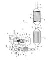
図1は、本実施形態に係る排気浄化装置の概略構成を示す図である。図1に示すように、排気浄化装置10は、複数の排気浄化用触媒と排気浄化用フィルタとを有し、これら複数の排気浄化用触媒と排気浄化用フィルタとは、車両に搭載される多気筒ディーゼルエンジン(以下、単にエンジンという)11の排気管(排気通路)12に介装されている。
FIG. 1 is a diagram showing a schematic configuration of an exhaust emission control device according to the present embodiment. As shown in FIG. 1, the
エンジン11は、シリンダヘッド13とシリンダブロック14とを有し、シリンダブロック14の各シリンダボア15内には、ピストン16が往復移動自在に収容されている。そして、このピストン16とシリンダボア15とシリンダヘッド13とで燃焼室17が形成されている。なお、ピストン16は、コンロッド18を介してクランクシャフト19に接続されており、ピストン16の往復運動によってクランクシャフト19が回転するようになっている。
The
またシリンダヘッド13には吸気ポート20が形成され、この吸気ポート20には吸気マニホールド21を含む吸気管(吸気通路)22が接続されている。また、吸気ポート20には、吸気弁23が設けられておりこの吸気弁23によって吸気ポート20が開閉されるようになっている。また、シリンダヘッド13には、排気ポート24が形成され、この排気ポート24には、排気マニホールド25を含む排気管(排気通路)12が接続されている。なお、排気ポート24には排気弁26が設けられており、吸気ポート20と同様に、排気ポート24はこの排気弁26によって開閉されるようになっている。そして、これら吸気管22及び排気管12の途中には、ターボチャージャ27が設けられ、排気管12のターボチャージャ27の下流側には、排気浄化装置10を構成する排気浄化用触媒及び排気浄化用フィルタが介装されている。
An
ターボチャージャ27は、図示しないタービンと、このタービンに連結されたコンプレッサとを有し、エンジン11からターボチャージャ27内に排気ガスが流れ込むと、排気ガスの流れによってタービンが回転し、このタービンの回転に伴ってコンプレッサが回転して吸気管22aからターボチャージャ27内に空気を吸い込んで加圧するようになっている。そして、ターボチャージャ27で加圧された空気は、吸気管22bを介してエンジン11の各吸気ポート20に供給される。
The
なお、シリンダヘッド13には、各気筒の燃焼室17内に燃料を直噴射する電子制御式の燃料噴射弁31が設けられており、この燃料噴射弁31には、図示しないコモンレールから所定の燃圧に制御された高圧燃料が供給されるようになっている。
The
ここで、本実施形態では、ターボチャージャ27の下流側の排気管12に、排気浄化用触媒であるディーゼル酸化触媒(以下、単に酸化触媒と称する)32及びNOxトラップ触媒33と、排気浄化用フィルタであるディーゼルパティキュレートフィルタ(DPF:Diesel Particulate Filter:以下、DPFと称する)34とが上流側から順に配されている。また、詳しくは後述するが、ターボチャージャ27と酸化触媒32との間の排気管12aには、還元剤(添加剤)である燃料(軽油)を排気管12a内に噴射するインジェクタ50が設けられている。
Here, in the present embodiment, a diesel oxidation catalyst (hereinafter simply referred to as an oxidation catalyst) 32 and a
酸化触媒32は、例えば、セラミックス材料で形成されたハニカム構造の担体に、白金(Pt)、パラジウム(Pd)等の貴金属が担持されてなる。酸化触媒32では、排気ガスが流入すると、排気ガス中の一酸化窒素(NO)が酸化されて二酸化窒素(NO2)が生成される。また、酸化触媒32における酸化反応が起こるには、酸化触媒32が所定温度以上に加熱されている必要があるため、酸化触媒32は可及的にエンジン11に近い位置に配されていることが好ましい。酸化触媒32がエンジン11の熱によって加熱され、エンジン始動時等であっても、比較的短時間で酸化触媒32を所定温度以上に加熱することができるからである。
The
NOxトラップ触媒33は、例えば、酸化アルミニウム(AL2O3)からなるハニカム構造の担体に、白金(Pt)、パラジウム(Pd)等の貴金属が担持されると共に、トラップ剤としてバリウム(Ba)等のアルカリ金属、あるいはアルカリ土類金属が担持されてなる。そして、NOxトラップ触媒33では、酸化雰囲気においてNOx、すなわち、酸化触媒32で生成されたNO2、また酸化触媒32で酸化されずに排気ガス中に残存するNOを一旦トラップし、例えば、一酸化炭素(CO)、炭化水素(HC)等を含む還元雰囲気中において、NOxを放出して窒素(N2)等に還元する。
In the
なお、酸化触媒32で生成されたNO2の多くはNOxトラップ触媒33によって吸着・分解(還元)され、吸着・分解されなかった残りのNO2はDPF34での反応により浄化されるようになっている。
Most of the NO 2 produced by the
通常、エンジン11から排出される排気ガスの大部分はNOが占めておりHCの量は極めて少ないため、NOxトラップ触媒33内が酸化雰囲気となり、NOxトラップ触媒33ではNOxが吸着されるのみで吸着されたNOxが分解(還元)されることはない。このため、NOxトラップ触媒33に所定量のNOxが吸着されると、ターボチャージャ27と酸化触媒32との間の排気管12aに固定されたインジェクタ50から添加剤である燃料(軽油)が噴射されるようになっている。これにより、燃料が混合された排気ガスが酸化触媒32を通過してNOxトラップ触媒33に供給され、NOxトラップ触媒33内が還元雰囲気となり、吸着されたNOxが分解(還元)される。
Normally, most of the exhaust gas discharged from the
また、DPF34は、例えば、セラミックス材料で形成されたハニカム構造のフィルタであり、DPF34内には、上流側端部が開放され下流側端部が閉塞された排気ガス通路38と下流側端部が開放され上流側端部が閉塞された排気ガス通路39とが交互に配列されている。そして、排気ガスは、まず上流側端部が開放された排気ガス通路38に流入し、隣接する排気ガス通路39との間に設けられた多孔質の壁面から下流側端部が開放された排気ガス通路39に流入して下流側に流出し、この過程において排気ガス中の微粒子状物質(PM)が、壁面に衝突したり吸着されたりして捕捉される。
The
また、捕捉されたPMは、排気ガス中のNO2によって酸化(燃焼)されCO2として排出され、またDPF34内に残存するNO2はN2に分解されて排出されるようになっている。すなわち、DPF34では、排気ガスを浄化して、PM及びNOxの排出量を大幅に低減できるようになっている。また、PMが燃焼されることで、DPF34の性能がある程度再生される。
The trapped PM is oxidized (combusted) by NO 2 in the exhaust gas and discharged as CO 2 , and NO 2 remaining in the
ここで、通常は、上述したようにNOxはNOxトラップ触媒33で吸着されるため、DPF34に供給される排気ガス中のNO2の量は少なく、DPF34にはPMが徐々に堆積されていく。そして、DPF34に所定量のPMが堆積すると、排気管12aに固定されているインジェクタ50から所定量の燃料が噴射されるようになっている。上述したように排気ガスに燃料が混合されると、NOxトラップ触媒33では吸着されたNOxが還元されるため、排気ガスに含まれているNOx(NO2)はNOxトラップ触媒33で吸着されずにDPF34に供給される。これにより、DPF34におけるPMの燃焼が促進されるようになっている。
Here, since NOx is normally adsorbed by the
なお、これら酸化触媒32、NOxトラップ触媒33及びDPF34の上流側近傍及びDPF34の下流側近傍には、それぞれ排気温センサ40が設けられており、これら複数の排気温センサ40によって、酸化触媒32、NOxトラップ触媒33及びDPF34に流入する排気ガスの温度と、酸化触媒32、NOxトラップ触媒33及びDPF34から排出される排気ガスの温度を検出している。さらに、酸化触媒32及びDPF34の上流側近傍には、排気ガス中の酸素濃度を検出するための酸素濃度センサ41が設けられている。また、車両には、図示しないが電子制御ユニット(ECU)が設けられており、このECUには、入出力装置、制御プログラムや制御マップ等の記憶を行う記憶装置、中央処理装置及びタイマやカウンタ類が備えられている。そして、このECUが、上記各センサからの情報に基づいて、エンジン11及び排気浄化装置10の総合的な制御を行っている。
An
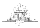
図2は、本実施形態に係る装着部材の断面図であり、図3は、図2のA−A′断面図であり、図4は、図3のB−B′断面図である。これらの図2〜図4に示すように、還元剤(添加剤)である燃料を噴射するインジェクタ50は、本実施形態では、排気管12aに対して略直交する方向で配され、排気管12aに固定された装着部材60とこの装着部材60に固定される固定部材70とによって保持されている。
2 is a cross-sectional view of the mounting member according to the present embodiment, FIG. 3 is a cross-sectional view taken along line AA ′ of FIG. 2, and FIG. 4 is a cross-sectional view taken along line BB ′ of FIG. As shown in FIGS. 2 to 4, the
装着部材60には、その中央部にインジェクタ50が装着される貫通孔である装着孔61が形成されている。そして、この装着孔61に装着されたインジェクタ50は、ノズル51が開口する先端面52が排気管(排気通路)12a内に露出された状態、つまり先端部が排気ガスに晒された状態で、固定部材70によって装着部材60に固定されている。例えば、本実施形態では、固定部材70は、ボルト等の締結部材75によって装着部材60に固定されている。
The mounting
また装着部材60には、装着孔61の周囲に環状の冷却水路62が設けられている。この冷却水路62には、冷却水路62に冷却水を供給するための供給路81と、冷却水路62を循環した冷却水を排出するための排出路91とがそれぞれ接続されている。すなわち装着部材60には、供給路81を有する供給管80と、排出路91を有する排出管90とが接続され、これら供給路81(供給管80)及び排出路91(排出管90)が環状の冷却水路62の接線方向にそれぞれ延設されている。これら供給路81及び排出路91は、本実施形態では、冷却水路62の周方向の同一位置にそれぞれ接続されており、装着孔61の軸方向においては、供給路81が排出路91よりもインジェクタ50の基端部側に配されている。
The mounting
このような構成では、供給路81から供給された冷却水が冷却水路62を循環して排出路91から排出されることでインジェクタ50が冷却される。本実施形態では、上述のように供給路81及び排出路91が、冷却水路62の周方向の同一位置にそれぞれ接続されているため、供給路81から冷却水路62に導入された冷却水は、冷却水路62を少なくとも一周した後に排出路91から排出されるため、冷却水によってインジェクタ50を効率よく冷却することができる。
In such a configuration, the cooling water supplied from the
さらに本発明では、冷却水路62の供給路81との接続部近傍、すなわち供給路81の出口近傍の冷却水路62に、冷却水路62の側壁の一部が突出した突出部63によって水路の幅が狭められた狭窄部62aが設けられているため、インジェクタ50を効果的に冷却することができる。
Further, in the present invention, the width of the water channel is increased by the protruding
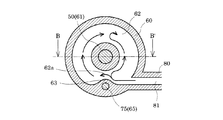
本実施形態に係る突出部63は、図3に示すように、冷却水路62の側壁の一部が供給路81から導入される冷却水がぶつかる位置まで半円状に突出して設けられている。そしてこのような突出部63によって冷却水路62の幅が狭められた狭窄部62aが形成されている。またこの突出部63は、本実施形態では、冷却水路62の深さ方向(装着孔61の軸方向)における一部、つまり供給路81に対向する領域のみに突出して設けられている(図2)。
As shown in FIG. 3, the protruding
このような構成では、供給路81から冷却水路62内に導入された冷却水が、突出部63にぶつかって乱流が発生することでインジェクタ50の冷却効果が向上する。具体的には、図3中に冷却水の流れを矢印で示すように、冷却水の一部は狭窄部62aを通過して冷却水路62を循環する主流(順流)となる。また突出部63にぶつかった冷却水の一部は逆流し、狭窄部62aを通過した主流と衝突する。そしてこの衝突により乱流が発生し、乱流が発生した部分の熱伝達率が向上する。また冷却水が狭窄部62aを通過することで主流の流速が上昇し、それに伴って上記衝突による乱流強度が高まるため、熱伝達率もさらに向上する。さらに、狭窄部62aにおける冷却水の流速上昇により狭窄部62aにおける冷却効果も高まる。これにより、インジェクタ50が効果的に冷却される。したがって、インジェクタ50の焼損、或いはノズル51の目詰まりといった問題の発生が抑制され、長期に亘って排気ガスを良好に浄化することができる。
In such a configuration, the cooling water introduced into the cooling
上記冷却水の衝突による乱流が生じる位置は、狭窄部62aのインジェクタ50を挟んだ反対側の領域であることが好ましい。このような位置で乱流が生じることで、インジェクタ50をさらに効果的に冷却することができる。なお冷却水路62内で乱流が生じる位置は、突出部63の形状、突出量等を調整することで所望の位置とすることができる。
The position where the turbulent flow due to the collision of the cooling water occurs is preferably an area on the opposite side across the
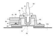
なお、このように所望の位置に乱流を発生させることができれば、突出部63の突出量、形状等は、特に限定されるものではない。例えば、本実施形態では、突出部63が供給路81に対向する領域のみに突出して設けられているが、これに限定されず、例えば、図5に示すように、冷却水路62の深さ方向に亘って連続的に設けられていてもよい。
In addition, if the turbulent flow can be generated at a desired position in this way, the protruding amount, shape, and the like of the protruding
また本実施形態では、突出部63を略半円状に突出させるようにし、突出部63の端面が曲面で構成されるようにしている。これにより、冷却水の流れは比較的スムーズになる。しかしながら突出部63の端面は、必ずしも曲面である必要はない。例えば、図6に示すように、突出部63を、断面が略三角形状となるように形成し、その端面が平面で構成されるようにしてもよい。
In the present embodiment, the protruding
さらに、上記のような突出部63を設けた構成においては、狭窄部62aの前後で冷却水路62の幅を徐々に変化させるようにしているが、例えば、図7に示すように、突出部63の供給路81とは反対側の部分にエッジ部63aを設け、狭窄部62aの後流における冷却水路62の幅を急激に増加させるようにしてもよい。この場合、図7中に矢印で示すように、突出部63の後流側でエッジ部63aに沿った流れ(渦)が発生する。そしてこの冷却水の流れ(渦)によっても熱伝達性が向上するため、インジェクタ50をさらに良好に冷却することができる。
Furthermore, in the configuration in which the
ところで、インジェクタ50を固定するための固定部材70は、上述したように締結部材75によって装着部材60に固定される。そして本実施形態では、上述した突出部63が、この締結部材75が締結される締結孔65を有するボス部を構成している。このように装着部材60に設けられた突出部63をボス部として有効利用することで、ボス部を設けるための領域を装着部材60に別途確保する必要がなくなる。すなわち、装着部材60に突出部63を設けることで、装着部材60の小型化を図ることができるという効果もある。
Incidentally, the fixing
以上、本発明の一実施形態について説明したが、本発明は、この実施形態に限定されるものではない。例えば、上述の実施形態では、供給路81及び排出路91が冷却水路62の周方向の同一位置にそれぞれ接続されていたが、勿論、これに限定されず、供給路81と排出路91とは、冷却水路62の周方向の異なる位置にそれぞれ接続されていてもよい。さらに、上述の実施形態では、供給路81及び排出路91のそれぞれが冷却水路62の接線方向に沿って延設された構成を例示したが、少なくとも供給路81が冷却水路62の接線方向に沿って延設されていればよく、排出路91の延設方向は特に限定されない。
Although one embodiment of the present invention has been described above, the present invention is not limited to this embodiment. For example, in the above-described embodiment, the
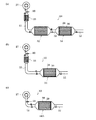
また例えば、上述の実施形態では、排気浄化装置10として、排気管(排気通路)12に、排気浄化用触媒である酸化触媒32及びNOxトラップ触媒33と、排気浄化用フィルタであるとDPF34とを、上流側から酸化触媒32、NOxトラップ触媒33、DPF34の順で配置した例を挙げたが、これら排気浄化用触媒及び排気浄化用フィルタの配置及び種類は特に限定されるものではない。例えば、図8(a)に示すように、ターボチャージャ27の下流側の排気管12に、NOxトラップ触媒33、酸化触媒32、DPF34の順で配置するようにしてもよい。また、例えば、図8(b)に示すように、ターボチャージャ27の下流側の排気管12に、酸化触媒32を設けずに、NOxトラップ触媒33とDPF34とを順に配置するようにしてもよい。また、例えば、図8(c)に示すように、排気浄化用触媒を設けずに、触媒機能を有するDPF34Aのみを設けた構成としてもよい。すなわち、排気浄化用触媒を兼ねる排気浄化用フィルタであるDPF34Aのみを設けた構成としてもよい。何れにしても、排気浄化用触媒や排気浄化用フィルタの上流側に燃料等の添加剤を噴射するインジェクタを有する構成であれば、本発明を採用することができる。
Further, for example, in the above-described embodiment, as the
また、上述した実施形態では、NOxを分解(還元)する排気浄化用触媒として、燃料(軽油)を還元剤としてNOxを分解(還元)するNOxトラップ触媒を例示したが、これに限定されず、例えば、排気ガス中のNOxを選択的に触媒に吸着させ、還元剤としてアンモニアあるいは尿素をインジェクタから噴射してNOxを分解(還元)する、いわゆるSCR(Selective Catalytic Reduction)等であってもよい。 In the above-described embodiment, the NOx trap catalyst that decomposes (reduces) NOx using fuel (light oil) as a reducing agent is exemplified as the exhaust gas purification catalyst that decomposes (reduces) NOx, but is not limited thereto. For example, a so-called SCR (Selective Catalytic Reduction) that selectively adsorbs NOx in exhaust gas to a catalyst and injects ammonia or urea as a reducing agent from an injector to decompose (reduce) NOx may be used.
また、上述した実施形態では、添加剤として還元剤を添加した例を説明したが、添加剤は還元作用を目的としたものに限らず、排気系に添加するものであれば、例えば、燃焼による昇温を目的とした燃料等であってもよい。 In the above-described embodiment, the example in which the reducing agent is added as the additive has been described. However, the additive is not limited to the purpose of the reducing action, and if it is added to the exhaust system, for example, by combustion A fuel for the purpose of raising the temperature may be used.
さらに、上述した実施形態では過給器としてターボチャージャを備えている吸排気系の構成の一例を示しているが、特にこれに限定されず、例えば、過給器は必ずしも設ける必要はない。また、排気通路と吸気通路とにわたり冷却排気ガスの再循環路を有する冷却排気ガス再循環装置、いわゆるEGR装置を設けるようにしてもよい。 Furthermore, in the above-described embodiment, an example of the configuration of an intake / exhaust system including a turbocharger as a supercharger is shown. However, the present invention is not particularly limited thereto. For example, the supercharger is not necessarily provided. Further, a cooling exhaust gas recirculation device having a cooling exhaust gas recirculation passage between the exhaust passage and the intake passage, that is, a so-called EGR device may be provided.
10 排気浄化装置
11 エンジン
12 排気管(排気通路)
13 シリンダヘッド
14 シリンダブロック
15 シリンダボア
16 ピストン
17 燃焼室
18 コンロッド
19 クランクシャフト
20 吸気ポート
21 吸気マニホールド
22 吸気管
23 吸気弁
24 排気ポート
25 排気マニホールド
26 排気弁
27 ターボチャージャ
31 燃料噴射弁
32 酸化触媒
33 NOxトラップ触媒
34 DPF
40 排気温センサ
41 酸素濃度センサ
50 インジェクタ
51 ノズル
52 先端面
60 装着部材
61 装着孔
62 冷却水路
62a 狭窄部
63 突出部
63a エッジ部
65 締結孔
70 固定部材
75 締結部材
81 供給路
91 排出路
10
13
40
Claims (4)
前記装着部材の前記装着孔の周囲には冷却水が導入される環状の冷却水路が設けられ、該冷却水路には冷却水を供給するための供給路及び冷却水を排出するための排出路がそれぞれ接続されていると共に、少なくとも前記供給路が前記冷却水路の接線方向に沿って延設されており、
前記冷却水路の前記供給路との接続部近傍には、当該冷却水路の周方向における側壁の一部が突出した突出部によって水路の幅が狭められた狭窄部が設けられていることを特徴とする排気浄化装置。 An exhaust purification catalyst interposed in an exhaust passage communicating with the engine, an injector provided upstream of the exhaust purification catalyst and injecting an additive into the exhaust passage, and a mounting in which the injector is attached A mounting member having a hole,
An annular cooling water channel into which cooling water is introduced is provided around the mounting hole of the mounting member. The cooling water channel has a supply channel for supplying cooling water and a discharge channel for discharging the cooling water. Are connected to each other, and at least the supply channel extends along a tangential direction of the cooling water channel,
In the vicinity of the connection portion of the cooling water passage with the supply passage, a narrowed portion in which the width of the water passage is narrowed by a protruding portion in which a part of the side wall in the circumferential direction of the cooling water passage projects is provided. Exhaust purification device.
Priority Applications (4)
| Application Number | Priority Date | Filing Date | Title |
|---|---|---|---|
| JP2008183183A JP4450257B2 (en) | 2008-07-14 | 2008-07-14 | Exhaust purification device |
| RU2009126939/06A RU2425231C2 (en) | 2008-07-14 | 2009-07-13 | Device for exhaust gases cleaning |
| DE102009032978.1A DE102009032978B4 (en) | 2008-07-14 | 2009-07-14 | exhaust gas purification device |
| CN2009101607805A CN101629506B (en) | 2008-07-14 | 2009-07-14 | Exhaust gas purifying device |
Applications Claiming Priority (1)
| Application Number | Priority Date | Filing Date | Title |
|---|---|---|---|
| JP2008183183A JP4450257B2 (en) | 2008-07-14 | 2008-07-14 | Exhaust purification device |
Publications (2)
| Publication Number | Publication Date |
|---|---|
| JP2010019239A true JP2010019239A (en) | 2010-01-28 |
| JP4450257B2 JP4450257B2 (en) | 2010-04-14 |
Family
ID=41427497
Family Applications (1)
| Application Number | Title | Priority Date | Filing Date |
|---|---|---|---|
| JP2008183183A Expired - Fee Related JP4450257B2 (en) | 2008-07-14 | 2008-07-14 | Exhaust purification device |
Country Status (4)
| Country | Link |
|---|---|
| JP (1) | JP4450257B2 (en) |
| CN (1) | CN101629506B (en) |
| DE (1) | DE102009032978B4 (en) |
| RU (1) | RU2425231C2 (en) |
Cited By (3)
| Publication number | Priority date | Publication date | Assignee | Title |
|---|---|---|---|---|
| JP2015511682A (en) * | 2012-04-03 | 2015-04-20 | ローベルト ボッシュ ゲゼルシャフト ミット ベシュレンクテル ハフツング | Cooling device for connecting members |
| JP2016217138A (en) * | 2015-05-14 | 2016-12-22 | 株式会社日本自動車部品総合研究所 | Cooling structure |
| JP2020101112A (en) * | 2018-12-20 | 2020-07-02 | ロベルト・ボッシュ・ゲゼルシャフト・ミト・ベシュレンクテル・ハフツングRobert Bosch Gmbh | Reductant supplying device and cooling holder |
Families Citing this family (9)
| Publication number | Priority date | Publication date | Assignee | Title |
|---|---|---|---|---|
| GB201003784D0 (en) * | 2010-03-08 | 2010-04-21 | Johnson Matthey Plc | Improvement in control OPF emissions |
| DE102011102170A1 (en) * | 2011-05-20 | 2012-11-22 | Emitec Gesellschaft Für Emissionstechnologie Mbh | Injection device for injecting a fluid |
| DE102011087267A1 (en) * | 2011-11-29 | 2013-05-29 | Robert Bosch Gmbh | dosing |
| CN102635475A (en) * | 2012-05-05 | 2012-08-15 | 中国兵器工业集团第七〇研究所 | Installation device of fuel injector with independent cooling space |
| DE102012011991A1 (en) * | 2012-06-16 | 2013-12-19 | Volkswagen Aktiengesellschaft | Method for operating a metering valve and for operating an internal combustion engine |
| DE102014118415A1 (en) * | 2014-12-11 | 2016-06-16 | Dr. Ing. H.C. F. Porsche Aktiengesellschaft | Sensor device for determining the exhaust gas temperature of an internal combustion engine |
| GB2541200A (en) * | 2015-08-11 | 2017-02-15 | Ford Global Tech Llc | A method of reducing engine NOx emissions |
| US10018091B2 (en) * | 2016-11-17 | 2018-07-10 | Ford Global Technologies, Llc | Exhaust system |
| CN109630238B (en) * | 2019-01-28 | 2024-03-19 | 浙江科博达工业有限公司 | Fuel injection atomizer |
Family Cites Families (3)
| Publication number | Priority date | Publication date | Assignee | Title |
|---|---|---|---|---|
| DE4436397B4 (en) * | 1994-10-12 | 2006-06-08 | Robert Bosch Gmbh | Device for aftertreatment of exhaust gases |
| JP4248199B2 (en) * | 2002-07-11 | 2009-04-02 | 日野自動車株式会社 | Exhaust purification equipment |
| JP2005214100A (en) * | 2004-01-30 | 2005-08-11 | Hino Motors Ltd | Exhaust emission control device |
-
2008
- 2008-07-14 JP JP2008183183A patent/JP4450257B2/en not_active Expired - Fee Related
-
2009
- 2009-07-13 RU RU2009126939/06A patent/RU2425231C2/en not_active IP Right Cessation
- 2009-07-14 DE DE102009032978.1A patent/DE102009032978B4/en not_active Expired - Fee Related
- 2009-07-14 CN CN2009101607805A patent/CN101629506B/en active Active
Cited By (5)
| Publication number | Priority date | Publication date | Assignee | Title |
|---|---|---|---|---|
| JP2015511682A (en) * | 2012-04-03 | 2015-04-20 | ローベルト ボッシュ ゲゼルシャフト ミット ベシュレンクテル ハフツング | Cooling device for connecting members |
| US9598994B2 (en) | 2012-04-03 | 2017-03-21 | Robert Bosch Gmbh | Cooling device for connection piece |
| JP2016217138A (en) * | 2015-05-14 | 2016-12-22 | 株式会社日本自動車部品総合研究所 | Cooling structure |
| JP2020101112A (en) * | 2018-12-20 | 2020-07-02 | ロベルト・ボッシュ・ゲゼルシャフト・ミト・ベシュレンクテル・ハフツングRobert Bosch Gmbh | Reductant supplying device and cooling holder |
| JP7282513B2 (en) | 2018-12-20 | 2023-05-29 | ロベルト・ボッシュ・ゲゼルシャフト・ミト・ベシュレンクテル・ハフツング | Reductant supply device and cooling holder |
Also Published As
| Publication number | Publication date |
|---|---|
| DE102009032978A1 (en) | 2010-01-21 |
| JP4450257B2 (en) | 2010-04-14 |
| RU2009126939A (en) | 2011-01-20 |
| CN101629506A (en) | 2010-01-20 |
| DE102009032978B4 (en) | 2017-08-17 |
| RU2425231C2 (en) | 2011-07-27 |
| CN101629506B (en) | 2011-12-21 |
Similar Documents
| Publication | Publication Date | Title |
|---|---|---|
| JP4450257B2 (en) | Exhaust purification device | |
| JP5141900B2 (en) | Exhaust purification device | |
| JP5561486B2 (en) | Exhaust purification device | |
| JP4784761B2 (en) | Exhaust purification device | |
| KR20040060716A (en) | NOx AFTERTREATMENT SYSTEM AND METHOD FOR INTERNAL COMBUSTION ENGINES | |
| JP5013121B2 (en) | Exhaust purification device | |
| CN101680332A (en) | NOX purification system, and method for control of nox purification system | |
| JP2008128046A (en) | Exhaust gas purification device | |
| JP2011111945A (en) | Exhaust emission control device | |
| KR101795402B1 (en) | Exhaust system | |
| CN108060961B (en) | Reducing agent spray and exhaust flow guide and deflector | |
| JP2007198315A (en) | Exhaust emission control device for internal combustion engine and exhaust emission control method | |
| JP5041168B2 (en) | Exhaust purification device | |
| JP4671048B2 (en) | Exhaust purification device | |
| JP5605578B2 (en) | Exhaust purification device | |
| JP2008151039A (en) | Exhaust emission control device | |
| JP6020105B2 (en) | Diesel engine exhaust gas purification method and exhaust gas purification system | |
| JP5019069B2 (en) | Exhaust purification device | |
| JP4844766B2 (en) | Exhaust purification device | |
| JP4737463B2 (en) | Exhaust purification device | |
| JP2007247591A (en) | Additive supply device | |
| JP5228832B2 (en) | Exhaust gas purification system and exhaust gas purification method | |
| JP5470808B2 (en) | Exhaust gas purification system and exhaust gas purification method | |
| JP2010031768A (en) | Exhaust emission control device | |
| JP2007205308A (en) | Exhaust emission control method and exhaust emission control system |
Legal Events
| Date | Code | Title | Description |
|---|---|---|---|
| A521 | Written amendment |
Free format text: JAPANESE INTERMEDIATE CODE: A523 Effective date: 20091203 |
|
| TRDD | Decision of grant or rejection written | ||
| A01 | Written decision to grant a patent or to grant a registration (utility model) |
Free format text: JAPANESE INTERMEDIATE CODE: A01 Effective date: 20100106 |
|
| A01 | Written decision to grant a patent or to grant a registration (utility model) |
Free format text: JAPANESE INTERMEDIATE CODE: A01 |
|
| R150 | Certificate of patent or registration of utility model |
Ref document number: 4450257 Country of ref document: JP Free format text: JAPANESE INTERMEDIATE CODE: R150 Free format text: JAPANESE INTERMEDIATE CODE: R150 |
|
| A61 | First payment of annual fees (during grant procedure) |
Free format text: JAPANESE INTERMEDIATE CODE: A61 Effective date: 20100119 |
|
| FPAY | Renewal fee payment (event date is renewal date of database) |
Free format text: PAYMENT UNTIL: 20130205 Year of fee payment: 3 |
|
| FPAY | Renewal fee payment (event date is renewal date of database) |
Free format text: PAYMENT UNTIL: 20140205 Year of fee payment: 4 |
|
| LAPS | Cancellation because of no payment of annual fees |