JP2006523121A - Apparatus, system, and method for securing or supporting tissue within a target body region, such as a pharyngeal canal, for the treatment of sleep disordered breathing, including obstructive sleep apnea - Google Patents
Apparatus, system, and method for securing or supporting tissue within a target body region, such as a pharyngeal canal, for the treatment of sleep disordered breathing, including obstructive sleep apnea Download PDFInfo
- Publication number
- JP2006523121A JP2006523121A JP2006507427A JP2006507427A JP2006523121A JP 2006523121 A JP2006523121 A JP 2006523121A JP 2006507427 A JP2006507427 A JP 2006507427A JP 2006507427 A JP2006507427 A JP 2006507427A JP 2006523121 A JP2006523121 A JP 2006523121A
- Authority
- JP
- Japan
- Prior art keywords
- implant
- magnetic
- magnet
- tissue
- pharyngeal
- Prior art date
- Legal status (The legal status is an assumption and is not a legal conclusion. Google has not performed a legal analysis and makes no representation as to the accuracy of the status listed.)
- Pending
Links
Images


Classifications
-
- A—HUMAN NECESSITIES
- A61—MEDICAL OR VETERINARY SCIENCE; HYGIENE
- A61F—FILTERS IMPLANTABLE INTO BLOOD VESSELS; PROSTHESES; DEVICES PROVIDING PATENCY TO, OR PREVENTING COLLAPSING OF, TUBULAR STRUCTURES OF THE BODY, e.g. STENTS; ORTHOPAEDIC, NURSING OR CONTRACEPTIVE DEVICES; FOMENTATION; TREATMENT OR PROTECTION OF EYES OR EARS; BANDAGES, DRESSINGS OR ABSORBENT PADS; FIRST-AID KITS
- A61F2/00—Filters implantable into blood vessels; Prostheses, i.e. artificial substitutes or replacements for parts of the body; Appliances for connecting them with the body; Devices providing patency to, or preventing collapsing of, tubular structures of the body, e.g. stents
-
- A—HUMAN NECESSITIES
- A61—MEDICAL OR VETERINARY SCIENCE; HYGIENE
- A61F—FILTERS IMPLANTABLE INTO BLOOD VESSELS; PROSTHESES; DEVICES PROVIDING PATENCY TO, OR PREVENTING COLLAPSING OF, TUBULAR STRUCTURES OF THE BODY, e.g. STENTS; ORTHOPAEDIC, NURSING OR CONTRACEPTIVE DEVICES; FOMENTATION; TREATMENT OR PROTECTION OF EYES OR EARS; BANDAGES, DRESSINGS OR ABSORBENT PADS; FIRST-AID KITS
- A61F5/00—Orthopaedic methods or devices for non-surgical treatment of bones or joints; Nursing devices; Anti-rape devices
- A61F5/56—Devices for preventing snoring
- A61F5/566—Intra-oral devices
-
- A—HUMAN NECESSITIES
- A61—MEDICAL OR VETERINARY SCIENCE; HYGIENE
- A61P—SPECIFIC THERAPEUTIC ACTIVITY OF CHEMICAL COMPOUNDS OR MEDICINAL PREPARATIONS
- A61P11/00—Drugs for disorders of the respiratory system
- A61P11/16—Central respiratory analeptics
-
- A—HUMAN NECESSITIES
- A61—MEDICAL OR VETERINARY SCIENCE; HYGIENE
- A61P—SPECIFIC THERAPEUTIC ACTIVITY OF CHEMICAL COMPOUNDS OR MEDICINAL PREPARATIONS
- A61P25/00—Drugs for disorders of the nervous system
- A61P25/20—Hypnotics; Sedatives
-
- A—HUMAN NECESSITIES
- A61—MEDICAL OR VETERINARY SCIENCE; HYGIENE
- A61F—FILTERS IMPLANTABLE INTO BLOOD VESSELS; PROSTHESES; DEVICES PROVIDING PATENCY TO, OR PREVENTING COLLAPSING OF, TUBULAR STRUCTURES OF THE BODY, e.g. STENTS; ORTHOPAEDIC, NURSING OR CONTRACEPTIVE DEVICES; FOMENTATION; TREATMENT OR PROTECTION OF EYES OR EARS; BANDAGES, DRESSINGS OR ABSORBENT PADS; FIRST-AID KITS
- A61F5/00—Orthopaedic methods or devices for non-surgical treatment of bones or joints; Nursing devices; Anti-rape devices
- A61F5/56—Devices for preventing snoring
Landscapes
- Health & Medical Sciences (AREA)
- Life Sciences & Earth Sciences (AREA)
- Engineering & Computer Science (AREA)
- Veterinary Medicine (AREA)
- Public Health (AREA)
- General Health & Medical Sciences (AREA)
- Animal Behavior & Ethology (AREA)
- Biomedical Technology (AREA)
- Vascular Medicine (AREA)
- Heart & Thoracic Surgery (AREA)
- Pulmonology (AREA)
- Chemical & Material Sciences (AREA)
- Oral & Maxillofacial Surgery (AREA)
- Pharmacology & Pharmacy (AREA)
- Nuclear Medicine, Radiotherapy & Molecular Imaging (AREA)
- Medicinal Chemistry (AREA)
- General Chemical & Material Sciences (AREA)
- Chemical Kinetics & Catalysis (AREA)
- Orthopedic Medicine & Surgery (AREA)
- Cardiology (AREA)
- Organic Chemistry (AREA)
- Transplantation (AREA)
- Nursing (AREA)
- Bioinformatics & Cheminformatics (AREA)
- Otolaryngology (AREA)
- Anesthesiology (AREA)
- Neurology (AREA)
- Neurosurgery (AREA)
- Prostheses (AREA)
- Orthopedics, Nursing, And Contraception (AREA)
- Respiratory Apparatuses And Protective Means (AREA)
Abstract
システムならびに方法は、生理的状態たとえば睡眠時呼吸障害の非常に効果的な治療を可能とする移植構造物、および/または移植装置、および/または外科的移植技法を実現する。動物組織に移植さるべき寸法と構成とを有する生体適合性ポリマーマトリックスと、該生体適合性ポリマーマトリックスと結合されて、所望の極性を有するように磁化された磁性粒子とを含むインプラントが提供される。磁性粒子は等方性材料または異方性材料を含む。The systems and methods provide implant structures and / or implant devices and / or surgical implant techniques that allow for highly effective treatment of physiological conditions such as sleep disordered breathing. Provided is an implant comprising a biocompatible polymer matrix having a size and configuration to be implanted in animal tissue, and magnetic particles bonded with the biocompatible polymer matrix and magnetized to have a desired polarity. . The magnetic particles include isotropic materials or anisotropic materials.
Description
(関連出願)
本出願は、本引証によりその内容を本願明細書に引用したものとする、2003年11月20日出願の、「身体部域内たとえば咽頭管内の組織を固定するための装置、システムならびに方法」を名称とする合衆国特許出願第10/718,254号、2003年9月6日出願の、「咽頭管内の組織虚脱に抗するための磁力装置、システムならびに方法」を名称とする合衆国特許出願第10/656,861号、2002年9月6日出願の、「上気道系の組織を運動および/または抑制するためのシステムならびに方法」を名称とする合衆国特許出願第10/236,455号、2003年1月22日出願の、「閉塞型睡眠時無呼吸における上気道虚脱の治療のための磁気副子装置ならびに方法」を名称とする合衆国仮特許出願第60/441,639号および2003年3月20日出願の、「いびきおよび睡眠時無呼吸を含む睡眠関連呼吸障害を治療するための装置ならびに方法」を名称とする合衆国仮特許出願第60/456,164号の各権益を請求する。
(Related application)
This application is a "device, system and method for immobilizing tissue within a body region, eg, the pharyngeal canal," filed Nov. 20, 2003, the contents of which are incorporated herein by reference. US patent application Ser. No. 10 / 718,254, filed Sep. 6, 2003, entitled “Magnetic devices, systems and methods for resisting collapse of tissue in the pharyngeal canal” US patent application Ser. No. 10 / 236,455, filed Sep. 6,656,861, filed Sep. 6, 2002, entitled “Systems and Methods for Exercise and / or Suppression of Upper Airway Tissue”. US Provisional Patent Application No. 60/441, entitled “Magnetic splint device and method for treatment of upper airway collapse in obstructive sleep apnea,” filed January 22, No. 639 and US Provisional Patent Application No. 60 / 456,164 filed Mar. 20, 2003, entitled “Apparatus and Method for Treating Sleep-related Respiratory Disorders, including Snoring and Sleep Apnea”. Claim each interest.
(発明の分野)
本発明は、閉塞型睡眠時無呼吸を含む睡眠時呼吸障害の治療のために目標身体部域内たとえば咽頭管内の組織を固定もしくは支持する装置、システムならびに方法に関する。
(Field of Invention)
The present invention relates to devices, systems and methods for securing or supporting tissue within a target body region, such as the pharyngeal canal, for the treatment of sleep disordered breathing, including obstructive sleep apnea.
(発明の背景)
(I. 睡眠時無呼吸の特徴)
1965年に初めて記述された睡眠時無呼吸は、睡眠中の短時間の呼吸中断(10秒以上)を特徴とする呼吸障害である。睡眠時無呼吸は一般的なものであるとはいえ、1800万人ものアメリカ人が侵されている、深刻な、生命を脅かす危険を秘めた状態である。
(Background of the Invention)
(I. Characteristics of sleep apnea)
Sleep apnea, first described in 1965, is a disorder of breathing characterized by brief breath interruptions (over 10 seconds) during sleep. Although sleep apnea is common, it is a serious, life-threatening danger that affects 18 million Americans.
睡眠時無呼吸には中枢型と閉塞型との2タイプがある。比較的稀な中枢型睡眠時無呼吸は、脳が、たとえば脳幹傷害または脳幹損傷の結果として、呼吸を開始するための適切な信号を呼吸筋に送ることができない場合に生ずる。機械的肺換気が呼吸持続の確保に利用し得る唯一の治療法である。 There are two types of sleep apnea, central and obstructive. A relatively rare central sleep apnea occurs when the brain is unable to send an appropriate signal to the respiratory muscles to initiate breathing, for example as a result of brainstem injury or brainstem injury. Mechanical lung ventilation is the only treatment that can be used to ensure sustained breathing.
閉塞型睡眠時無呼吸(OSA)は遥かに一般的である。これは、より広い睡眠時呼吸障害群(SDB)を形成しているいくつかの疾病の一つである。この障害群は習慣性のいびきからOSAにまで及んでいる。普通、咽頭上部の筋肉は気流が肺に達するように気道を開いた状態に保っている。上気道の筋肉が弛緩して垂下すると、弛緩した組織は呼吸の間に気流が組織を通過するたびに振動して、いびきを生じることがある。男性の約半数、女性の約25%がいびきをかくが、その大半は50歳以上の男女である。 Obstructive sleep apnea (OSA) is much more common. This is one of several diseases that form a broader sleep disordered breathing group (SDB). This disorder range from addictive snoring to OSA. Normally, the muscles in the upper pharynx are kept open so that the airflow reaches the lungs. When the upper airway muscles relax and droop, the relaxed tissue may vibrate each time airflow passes through the tissue during breathing, causing snoring. About half of men and 25% of women are snoring, most of them are men and women over the age of 50.
もっと深刻な場合には、気道は閉塞して、呼吸は苦しい、騒がしいものとなり、まったく止まってしまうことさえもある。ある夜には、不随意の呼吸休止ないし「無呼吸現象」の回数がきわめて高い頻度に達することもある。こうした呼吸休止は、いびきをかく人が皆OSAであるとはかぎらないとはいえ、ほとんどの場合に無呼吸現象の間にいびきの発生を伴っている。 In more severe cases, the airways become obstructed, breathing becomes painful, noisy, and may even stop at all. On some nights, the frequency of involuntary breathing pauses or “apnea events” can be very high. Such breathing pauses are often accompanied by the occurrence of snoring during apnea, although not all snoring people are OSA.
肺への吸気の欠乏は血中の酸素濃度の低下と二酸化炭素濃度の増加とを生ずる。酸素濃度と二酸化炭素濃度の変動は脳に、呼吸を再開し、覚醒するように警告を発する。活力を回復させる深い睡眠が頻繁に中断される結果、早朝の頭痛、日中の非常な眠さ、うつ状態、興奮性および学習および記憶の困難が生ずることが多い。 Lack of inspiration to the lungs results in a decrease in blood oxygen levels and an increase in carbon dioxide levels. Variations in oxygen and carbon dioxide levels alert the brain to resume breathing and to wake up. Frequent interruptions in deep sleep that restore vitality often result in early morning headaches, very daytime sleepiness, depression, excitability, and learning and memory difficulties.
医学界は、中度もしくは深刻な閉塞型睡眠時無呼吸のある人々には心臓発作、高血圧症および脳卒中の発生頻度が高いことを意識するに至っている。睡眠時無呼吸症患者のおよそ50%までが高血圧症を有していると推定される。 The medical community has become aware that people with moderate or severe obstructive sleep apnea have a higher incidence of heart attacks, hypertension and stroke. It is estimated that up to approximately 50% of sleep apnea patients have hypertension.
無呼吸現象が発生すると直ちに、睡眠中の人は正常な呼吸機能を続行することができなくなり、血中酸素飽和濃度は低下する。脳はこの状態を自覚し、睡眠中の人はもがき、あえぐようになる。次いで呼吸は再開されるが、ふたたび連続的な無呼吸現象を伴うことが多い。これは血圧の急激な変動補償によって心臓と血管にダメージをもたらす可能性を有している。無呼吸現象が起こるたびに、睡眠中の人は部分的に眠りから起こされ、結果として睡眠の質は非常に低下し、それに伴って日中の疲労感がもたらされる。 As soon as the apnea event occurs, the sleeping person is unable to continue normal respiratory function and the blood oxygen saturation level is reduced. The brain is aware of this condition, and sleeping people struggle and pant. Breathing is then resumed, but is often accompanied by a continuous apnea event. This has the potential to cause damage to the heart and blood vessels by compensating for rapid fluctuations in blood pressure. Each time an apneic event occurs, the sleeping person is partially awakened from sleep, resulting in a very poor quality of sleep, accompanied by daytime fatigue.
ある程度の無呼吸現象は通例すべての人にみられるものであるが、疾病の深刻さと健康損傷の可能性とを決定するものは閉塞の頻度である。閉塞の発生頻度が高ければ、矯正対策が講じられなければならない。 Some degree of apnea is usually seen in all people, but it is the frequency of obstruction that determines the severity of the disease and the potential for health damage. If the frequency of blockage is high, corrective measures must be taken.
(II. 睡眠と上気道の解剖図)
図1Aと1Bが示しているように、上気道は、鼻の先端に位置する鼻弁で開始して喉頭にまで達する管からなっている。この管に沿った組織全体は動的でかつ呼吸周期に対して反応するが、ただし、咽頭管構造物、つまり― 鼻腔後部から発して声門上喉頭に繋がる部分で終わる ― 気道部域の組織のみは全面的に虚脱性を有している。咽頭構造物とこの部域内の個々の解剖学的要素は、咽頭壁、舌根、谷、舌骨とその付加物、軟口蓋と口蓋垂、口蓋扁桃と関連柱組織および喉頭蓋を含んでいる。
(II. Anatomy of sleep and upper airway)
As FIGS. 1A and 1B show, the upper airway consists of a tube that starts with a nasal valve located at the tip of the nose and reaches the larynx. The entire tissue along this tube is dynamic and responds to the respiratory cycle, except that it ends in the pharyngeal canal structure, the part that originates from the posterior nasal cavity and connects to the supraglottic larynx-only the tissue in the airway area Is totally collapsible. The pharyngeal structure and the individual anatomical elements within this area include the pharyngeal wall, tongue base, valley, hyoid bone and its appendages, soft palate and uvula, palatine tonsils and associated columnar tissue, and epiglottis.
上気道の断面積は呼吸周期の相と共に変化する。吸息の開始時(相I)に、気道は膨張し始め、次いで、残りの吸息の間中比較的一定に保たれる(相II)。呼息の開始時(相III)に、気道は拡張し始めて最大直径に達し、次いで縮小することから、呼息の終了時(相IV)にそれは最も狭くなる。これは上気道拡張筋が最も不活発で、管腔内陽圧が最も低い時に相当している。したがって、上気道は呼息終期に、虚脱、閉塞する最も大きな可能性を有している。Schwab RJ,Goldberg AN.Upper Airway Assesment: Radiographic and other Imaging Techniques.Otolaryngol Clin North Am 1998;31:931−968。 The upper airway cross-sectional area changes with the phase of the respiratory cycle. At the beginning of inspiration (phase I), the airway begins to expand and then remains relatively constant throughout the remaining inspiration (phase II). At the beginning of exhalation (phase III), the airway begins to dilate and reaches its maximum diameter and then contracts, so it becomes narrowest at the end of exhalation (phase IV). This corresponds to the time when the upper airway dilator is the least active and the positive intraluminal pressure is the lowest. Therefore, the upper airway has the greatest potential to collapse and block at the end of expiration. Schwab RJ, Goldberg AN. Upper Airway Assessment: Radiographic and other Imaging Techniques. Otalyngol Clin North Am 1998 ; 31: 931-968.
睡眠は上気道拡張筋の活動の減退を特徴としている。閉塞型睡眠時無呼吸症患者(OSA)と、場合により、その他の、閉塞型睡眠時呼吸障害(SDB)と称される疾病群の大半が含まれる障害を有する個人については、こうした筋肉機能の変化が咽頭狭窄および虚脱の原因であると考えられている。OSA患者のこうした現象については、考えられ得る2つの原因が理論化されている。一方は、これらの患者の睡眠中の気道拡張筋緊張は非無呼吸症患者のそれよりも低下しているというものである(神経学的理論)。他方は、睡眠中の拡張筋活動の減退はすべての個人に等しくみとめられるが、無呼吸症患者は構造的に不安定な咽頭を有しているというものである(解剖学的理論)。いずれの理論も事実、OSAの一因を明らかにしているといってよいが、最近の研究は、OSA患者は生来、構造的に狭窄し、虚脱しやすい咽頭を有しているとの見解を裏付けているように思われる。Isono S.Remmers J,Tanaka A Sho Y,Sato J,Nishino T.Anotomy of Pharynx in Patients with Obstructive Sleep Apnea and in Normal Subjects.J Appl Physiol 1997: 82: 1319−1326。 Sleep is characterized by diminished upper airway dilator muscle activity. For individuals with obstructive sleep apnea (OSA) and possibly other individuals with disabilities that include most of the disease group called obstructive sleep disordered breathing (SDB), Changes are thought to be responsible for pharyngeal stenosis and collapse. Two possible causes for this phenomenon in OSA patients have been theorized. One is that airway dilator muscle tone during sleep in these patients is lower than that in non-apnea patients (neurological theory). On the other hand, diminished dilated muscle activity during sleep is equally seen in all individuals, but apnea patients have a structurally unstable pharynx (anatomical theory). Both theories may in fact reveal a contribution to OSA, but recent studies have taken the view that OSA patients inherently have a structurally stenotic and prone pharynx It seems to support. Isono S. Remmers J, Tanaka A Sho Y, Sato J, Nishino T .; Annoty of Pharynx in Patents with Obstructive Sleep Apnea and in Normal Subjects. J Appl Physiol 1997 : 82: 1319-1326.
解剖学的閉塞は特定の部位、たとえば口蓋帆咽頭レベルで際立っていることが多いが[Isono,Ibid]、閉塞圧の研究[Isono,Ibid]は、狭窄と虚脱はふつう咽頭の全長にそって発生するとのことを示すダイナミックファストMRI撮像を裏付けている。Shellock FG,Schatz CJ,Julien P,Silverman JM,Steinberg F,Foo TKF,Hopp ML,Westbrook PR.Occlusion and Narrowing of the Pharyngeal Airway in Obstructive Sleep Apnea: Evaluation by Ultrafast Spoiled GRASS MR Imaging.Am J of Roentgenology 1992: 158: 1019−1024。 Anatomical occlusion often stands out at a specific site, for example at the level of the palatal pharynx [Isono, Ibid], but studies of occlusion pressure [Isono, Ibid] show that stenosis and collapse usually follow the entire length of the pharynx. It supports dynamic fast MRI imaging that indicates that it occurs. Shellock FG, Schatz CJ, Julien P, Silverman JM, Steinberg F, Food TKF, Hopp ML, Westbrook PR. Occlusion and Narrowing of the Circular Airway in Observative Sleep Apnea: Evaluation by Ultrafast Spoiled GRASS MR Imaging. Am J of Roentgenology 1992 : 158: 1019-1024.
(III. 従来の治療法)
これまでのところ、上気道全体に沿った虚脱に対処する唯一の治療手段は、機械的陽圧呼吸装置たとえば持続的気道陽圧法(CPAP)装置である。その他のすべての方法、たとえばさまざまな外科的処置および口腔器具はその性質からして気道の特定部位(たとえば、口蓋、舌根および舌骨谷部位)に対処し得るが、咽頭壁部は対処されずに残されることとなる。OSAへの対処にあたり、外科的処置および器具をかなり上回るCPAPの成功率はこれによって説明することができよう。ただし、呼吸周期に対応する気道スプリントとして基本的に機能するCPAPは成功率が高いとはいえ、幾つかの非常に顕著な短所がある。それは着用、携行が面倒であり、社会的レベルで受け入れがたく、(たとえば、密室恐怖、マスク圧による顔面および鼻腔の不快感、気道刺激などの理由から)多くの人々はこれに耐えることができない。これらの要因によって長期装着遵守率は比較的低いものとなっている。ある研究が示すところによれば、患者の65%が6ヶ月後にはCPAP治療を止めている。
(III. Conventional therapy)
To date, the only therapeutic means to deal with collapse along the entire upper airway is a mechanical positive pressure breathing device, such as the continuous positive airway pressure (CPAP) device. All other methods, such as various surgical procedures and oral appliances, can address specific parts of the airway (eg, palate, tongue base and hyoid valley) by their nature, but not the pharyngeal wall. Will be left behind. In addressing OSA, this could explain the success rate of CPAP well over surgical procedures and instruments. However, although CPAP, which basically functions as an airway splint corresponding to the respiratory cycle, has a high success rate, it has some very significant disadvantages. It is cumbersome to wear and carry, unacceptable at the social level, and many people cannot tolerate this (for example, due to closed room fear, facial and nasal discomfort due to mask pressure, respiratory tract irritation, etc.) . Due to these factors, the long-term wearing compliance rate is relatively low. One study shows that 65% of patients cease CPAP treatment after 6 months.
睡眠時呼吸障害現象を減少または防止するための、簡単でかつ経済性に優れた装置、システムならびに方法に対するニーズは依然として存在している。 There remains a need for simple and economical devices, systems and methods for reducing or preventing sleep disordered breathing.
(発明の要旨)
本発明の一局面は、前記生理的状態の非常に効果的な治療を可能とする、移植構造物、および/または移植装置、および/または外科的移植技術を含むシステムならびに方法を提供することである。
(Summary of the Invention)
One aspect of the present invention is to provide a system and method, including an implant structure, and / or an implant device, and / or a surgical implant technique that allows for very effective treatment of the physiological condition. is there.
そこで1実施形態において、システムならびに方法は、咽頭管を襲う機能不全たとえば睡眠時呼吸障害、いびき、または睡眠時無呼吸の治療を提供する。システムならびに方法は、咽頭管内の少なくとも1つの咽頭構造物または少なくとも1つの解剖学的要素を含む目標組織部域に移植さるべき寸法と構成とを有するインプラントを提供する。システムならびに方法は、また、たとえば経皮アクセス路を通して、または外科的皮弁を形成することにより、または外科的ポケットを形成することにより、組織部域にインプラント206を着装するための少なくとも1つのツールおよび/または指示書も提供する。システムならびに方法は、また、粘膜内または粘膜下組織内に、または筋膜に対し、または筋肉に対しもしくは筋肉内にインプラントを安定化するための少なくとも1つのツールおよび/または指示書の提供も含むことができ、またはそれに代えて、ツールおよび/または指示書は、粘膜を通して安定化するのではなく、粘膜下組織または筋膜に対し、または筋肉に対しもしくは筋肉内にインプラントを安定化させることを可能にすることができる。システムおよび方法は、たとえばインプラントにさまざまな機械的固定材料を使用し得るようにするため、または移植部位に急速な線維形成を促す薬剤を利用し得るようにするため、または移植部位に抗生物質材料を供給するためにその他のツールおよび指示書を含むことができる。システムならびに方法は個別の要素を含むかまたはキットとして一括されていてもよい。各種指示書は、キットに含めてかつ/または臨床医のためのトレーニングプログラムまたはウェブサイトの一部として提供可能な、書面の形、電子文書の形または音声の形であってよい。
Thus, in one embodiment, the system and method provide a treatment for dysfunctions that attack the pharyngeal canal, such as sleep breathing disorder, snoring, or sleep apnea. The systems and methods provide an implant having a size and configuration to be implanted in a target tissue region that includes at least one pharyngeal structure or at least one anatomical element within the pharyngeal canal. The system and method also includes at least one tool for placing the
システムならびに方法は、気道虚脱および、閉塞型睡眠時呼吸障害群の全症状と関連した気道抵抗増加を治療するために使用することができる。システムならびに方法は、また、神経学的に関連した筋緊張異常障害における上気道支持を行うために使用することも可能である。 The system and method can be used to treat airway collapse and increased airway resistance associated with all symptoms in the obstructive sleep disordered breathing group. The system and method can also be used to provide upper airway support in neurologically related myotonia disorders.
本発明のもう一つの局面は、ポリマー結合された磁性インプラントを提供することである。インプラントは、動物組織に移植さるべき寸法と構成とを有する生体適合性ポリマーマトリックスからなっている。磁性粒子は生体適合性ポリマーマトリックスで結合される。磁性粒子は所望の極性を有するように磁化される。磁性粒子は生体適合性ポリマーマトリックス中で粒子密度の異なる一連の領域を形成するかまたは生体適合性ポリマーマトリックス中で基本的に均一な粒子密度を有していてよい。 Another aspect of the present invention is to provide a polymer-bonded magnetic implant. The implant consists of a biocompatible polymer matrix having the dimensions and configuration to be implanted in animal tissue. The magnetic particles are bound with a biocompatible polymer matrix. The magnetic particles are magnetized to have a desired polarity. The magnetic particles may form a series of regions of different particle density in the biocompatible polymer matrix or have an essentially uniform particle density in the biocompatible polymer matrix.
1実施形態において、少なくとも一方の磁石構造物は磁性粒子を含有した生体適合性ポリマーマトリックス内に封入されている。他方の磁石は個別の永久磁石またはポリマー結合された磁石からなっていてよい。 In one embodiment, at least one magnet structure is encapsulated within a biocompatible polymer matrix containing magnetic particles. The other magnet may consist of a separate permanent magnet or a polymer bonded magnet.
本発明のもう一つの局面は、集束させられた磁性インプラントを提供することである。インプラントは動物組織に移植さるべき寸法と構成とを有する構造物からなっている。この構造物は、硬強磁性材料からつくられた少なくとも1個の磁石と、磁石の少なくとも一部を被覆する軟強磁性材料を含む磁束シールドとで構成されている。磁束シールドはシールドによって被覆されていない方向に磁石磁界を集束させて増強する。 Another aspect of the present invention is to provide a focused magnetic implant. An implant consists of a structure having dimensions and configuration to be implanted in animal tissue. The structure is composed of at least one magnet made of a hard ferromagnetic material and a magnetic flux shield containing a soft ferromagnetic material covering at least a portion of the magnet. The magnetic flux shield focuses and strengthens the magnetic field in a direction not covered by the shield.
本発明のもう一つの局面は、安定化された磁性インプラントを提供することである。インプラントは動物組織に移植さるべき寸法と構成とを有する構造物からなっている。この構造物は、所望の磁極を有する、硬強磁性材料からつくられた少なくとも1個の磁石を含んでいる。所望の磁極と同じ磁極を有し、所望の磁極に対して直角または鋭角をなして配向される少なくとも1個の安定化磁石が設けられる。万一、他方の磁性インプラントに対して、回転に起因するインプラントの不整合が生じても、安定化磁石の存在によって磁界の力は整合状態に保たれる。結果として、不整合に起因する不安定化磁界は減少させられる。 Another aspect of the present invention is to provide a stabilized magnetic implant. An implant consists of a structure having dimensions and configuration to be implanted in animal tissue. The structure includes at least one magnet made of a hard ferromagnetic material having a desired magnetic pole. At least one stabilizing magnet is provided that has the same magnetic pole as the desired magnetic pole and is oriented at a right or acute angle to the desired magnetic pole. In the unlikely event that an implant misalignment occurs due to rotation with respect to the other magnetic implant, the magnetic field force is kept in alignment by the presence of the stabilizing magnet. As a result, the destabilizing magnetic field due to mismatch is reduced.
本発明のその他の特徴ならびに利点は以下の説明、図面および請求項から明らかとなろう。 Other features and advantages of the invention will be apparent from the following description, drawings and claims.
(詳細な説明)
本願明細書の開示は、技術に通じた者が本発明を実施し得るように、詳細かつ正確に記載されているが、ここに開示された物理的実施形態は単に本発明を例示しているにすぎず、本発明はその他のさまざまな構造によって実現されることもできる。好ましい実施形態が記載されているが、細部は請求項に記載された本発明の範囲を逸脱することなく変更することが可能である。
(Detailed explanation)
Although the disclosure herein is described in detail and accuracy so that those skilled in the art may practice the invention, the physical embodiments disclosed herein are merely illustrative of the invention. However, the present invention can be realized by various other structures. While preferred embodiments have been described, the details can be changed without departing from the scope of the invention as set forth in the claims.
(I. 組織を固定または支持するための磁力システム)
(A. 概要)
図1と2は、使用時に目標身体部域内の組織を固定または支持する磁力システム10を示している。図1と2において、目標身体部域は咽頭構造物と咽頭管内の個々の解剖学的要素とからなっている。目標とされる咽頭構造物とこの部域内の個々の解剖学的要素とは、咽頭壁、舌根、谷、軟口蓋と口蓋垂、口蓋扁桃と関連柱組織および喉頭蓋を含んでいる。これらの解剖学的部域は図1に示されている。
(I. Magnetic system for fixing or supporting tissue)
(A. Overview)
1 and 2 illustrate a
図示した特定の実施形態において(図2、参照)、磁力システム10は、咽頭壁に移植された1もしくは複数の強磁性体構造物12および/または舌の後部に移植された1もしくは複数の強磁性体構造物14を含んでいる。双方の強磁性体構造物12と14とは少なくとも1つの永久磁石からなっている。公知の永久磁石材料の例を挙げれば、ネオジミウム・鉄・ホウ素合金(NdFeB)、アルミニウム・ニッケル・コバルト合金(AlNiCo)およびサマリウムコバルト材料(SmCo)である。永久磁石は厚さ方向に、たとえば多重極面、半径方向等極、軸方向または直径方向などの多様な様式で磁化することができる。
In the particular embodiment shown (see FIG. 2), the
対向する構造物12と14との永久磁石は同じ磁気配向(N極−N極またはS極−S極)を有している。物理学の法則に従って、同じ極性の極は磁力によって互いに反撥する。磁気反撥の力は磁石の強さと極間の距離に依存している。
The permanent magnets of the opposing
対向する舌側磁石(単数または複数)と咽頭壁側磁石(単数または複数)との間の反発力は、気道内の生来の組織状態を改造するのに十分な強さに選択される。この反発力は、もしもそうでなければ組織虚脱とくに呼吸周期中の組織虚脱に至ることが懸念される気道内組織の現存する形態および/または運動性および/または形状を変化させる。移植された強磁性体構造物12と14とは、目前に迫った、つまり睡眠中の咽頭管に沿った虚脱に抗するために、組織を固定または支持する組織状態を確立するが、ただし組織虚脱が生じない場合には生来の組織を著しく硬直させることはない。
The repulsive force between the opposing lingual magnet (s) and the pharyngeal wall magnet (s) is selected to be strong enough to remodel the native tissue condition in the airway. This repulsive force changes the existing morphology and / or motility and / or shape of the tissue in the airways that would otherwise lead to tissue collapse, particularly tissue collapse during the respiratory cycle. Implanted
構造物12と14の向きは変えることができる。構造物12と14は(図2に示したように)組織内に水平に、および/または垂直に(たとえば図23Cおよび図26B、参照)、および/または斜めに、および/または中間的な向きに(たとえば傾けて)、および/またはこれらを組み合わせた形で装着することができる。
The orientation of the
構造物12と14の一方を咽頭管外に配置し、咽頭管内に移植された他方の構造物と磁気的な相互作用を行わせることができるとのことも看取されなければならない。生み出される磁力場は、これらの構造物の解剖学的な向きと所望の生理的効果とに応じ、引き合う場および/または反撥する場であってよい。移植された磁性体構造物および/または外部の磁性体構造物を使用した磁力システムのさまざまな実施形態は、本引証によりその内容を本願明細書に引用したものとする、2003年9月6日出願の、「咽頭管内の組織虚脱に抗するための磁力装置、システムならびに方法]を名称とする合衆国特許出願第10/656,861号に示されている。
It should also be observed that one of the
システム10は、気道虚脱および、閉塞型睡眠時呼吸障害群の全症状と関連した気道抵抗増加を治療するために使用することができる。システム10は、また、神経学的に関連した筋緊張異常障害における上気道支持を行うために使用することもできる。システム10は、また、組織改造および/または組織支持の必要性が証されるその他の身体部域に使用することもできる。
The
移植構造物12と14との固定または支持機能は患者にとって、安楽さの向上、移植構造物12,14に対する耐容性および生体受容を実現する。固定または支持機能は(望ましくない)咽頭管内の生来の組織のばね定数を安易に減衰(つまり硬直化)させることなく達成される。固定または支持機能は、咽頭管内の組織を硬直化することなく、組織を押しまたは引っ張る静的および/または動的な力の抑制的な適用によって達成される。移植構造物の寸法および構成は、移植の容易さと生体安楽性とを念頭におき、他方で同時に、移植部域の解剖学的構造とシステム10のその他の要素の配向とを考慮して、虚脱が差し迫っている場合に組織虚脱に抗する十分な静的および/または動的な力が供されるように選択される。したがって、移植構造物12,14は、生来の組織のばね定数を著しく減衰させることなく、患者にとっての親和性、耐容性および安楽さを提供する。
The fixation or support function of the
(B.磁石アレイ)
移植された強磁性体構造物12および/または14はそれぞれ、所定の所望の配向を有した単一または不連続の磁力源を備えている。たとえば、強磁性材料体を含む単一の永久磁石は所定の配向を有する単一の磁力源からなっていてよい。
(B. Magnet array)
Each implanted
移植される所与の強磁性体構造物12/14は、いかなる形状または構成のものであれ、選択された保護材料68(図2、参照)でコーティング、めっき、封入または蒸着処理されることができる。保護材料68は、構造物と身体の組織/体液との間の相互作用を防止するため、耐蝕性ある生体適合性境界面を供するように選択される。したがって、保護材料68は、好ましくは耐久的な組織境界面を形成し、構造物に寿命を与え、こうして構造物の疲労および/または欠陥の発生に対する抵抗力を供するように選択される。保護材料68は、所望の生体適合性、耐蝕性および耐久性を供する公知のさまざまなタイプの材料のうちから選択することができる。たとえば、保護材料68は、めっき、蒸着またはその他の方法でコーティングされた金、および/または銀、および/またはチタン材料からなっていてよい。別の例として、保護材料62はパリレンコーティングからなっていてよい。その他の例として、保護材料68はシリコンポリマー、無毒性エポキシ樹脂または医療用ポリウレタンまたは紫外線硬化性アクリル酸コポリマーからなっていてよい。
A given
保護材料68はまた、凝固防止剤および/または抗生物質を含んでいても、抗微生物性を有するかまたは抗微生物性表面を形成するように処理されてもよい。
The
(1.柔軟なキャリア上の不連続な永久磁石)
図3に示したように、強磁性体構造物12および/または14はそれぞれ、サポートキャリア18に載設されたユニットとして担持されるかまたはその他の方法で互いに直接に連結された不連続な永久磁石16の柔軟なまたは可撓性を有するアレイからなっていてよい。サポートキャリア18は好ましくは、磁石アレイに生体適合性、耐久性および柔軟性を付与する材料から作製される。キャリア40はたとえば軟質または半硬質材料たとえばポリカーボネート、シリコーンゴム、ポリウレタン、ヒドロゲルなど、または軟質または半硬質プラスチックおよび/または金属および/または繊維および/またはクロスおよび/またはセラミック材料で作製されてよい。
(1. Discontinuous permanent magnet on flexible carrier)
As shown in FIG. 3, each of the
キャリア18の材料は磁石16を包むか、または磁石16がキャリア18の表面に担持されてよい。キャリア18上またはその内部において磁石16が離間配置されていることにより、必要とされる所望の柔軟性がもたらされる。個々の磁石16は、所望の生理的反応が達成されるかぎりで、さまざまな形状 ― 角形、円形、球形、楕円形など ― を有していてよい。
The material of the
上記のタイプの柔軟な磁石アレイのさらなる詳細は、本引証によりその内容を本願明細書に引用したものとする、2002年9月6日出願の、「上気道系の組織を運動および/または抑制するためのシステムならびに方法」を名称とする共同出願中の合衆国特許出願第10/236,455号に見出すことができる。 Further details of flexible magnet arrays of the type described above are described in the application of September 6, 2002, entitled “Movement and / or Suppression of Upper Airway System”, the contents of which are hereby incorporated by reference. Can be found in co-pending US patent application Ser. No. 10 / 236,455 entitled “System and Method for Doing”.
(2.ポリマー結合された磁性体構造物)
磁性体構造物12および/または14は、図4に示したように、1または複数のポリマー結合された磁石20からなっていてよい。ポリマー結合された磁石20は生体適合性ポリマー24内に組み込まれた磁性粒子22からなっている。磁性粒子22は等方性材料または異方性材料たとえばNdFeB、SmCo、フェライトおよび/またはアルニコの粒子からなっていてよい。生体適合性ポリマー24はたとえばポリカーボネート、シリコーンゴム、ポリウレタン、シリコンエラストマまたは軟質もしくは半硬質プラスチックからなっていてよい。繊維および/またはクロスおよび/またはセラミック材料もポリマーマトリックスのうちに組み入れることができる。
(2. Polymer-bonded magnetic structure)
The
ポリマー結合された磁石20を形成するため、磁性粒子22は生体適合性ポリマー24と所望の割合で配合される。磁石20を形成するためのポリマー24と磁性粒子22との割合は、所望の柔軟性、弾性および磁石の強さに合わせて調整することができる。
To form the polymer bonded
生体適合性ポリマー24は所定の比率で磁性粒子22と混合され、この混合物が混和(つまり、捏和)される。混和された後、この混合物は所望の形状に成形されることができる。成形法はたとえば射出成形、圧縮成形、押し出しおよび圧延であってよい。
The
成形に続いて、成形された材料は必要に応じて切断または機械加工される。所望であれば、他の生体適合性ポリマーを使用して二次表面コーティングが行われてよい。別途方法としてまたは組み合わせ法として、成形済みの材料が生体適合性ポリマー層で被覆成形される二段階成形を行うことができる。 Following molding, the molded material is cut or machined as necessary. If desired, secondary surface coating may be performed using other biocompatible polymers. As a separate method or a combination method, a two-stage molding can be performed in which the molded material is coated with a biocompatible polymer layer.
仕上られた材料は、次いで、所望の極性を有するように磁化される。ポリマー結合された磁石20は、これにより、漏れ磁束が減少する単品として形成される。
The finished material is then magnetized to have the desired polarity. The polymer bonded
図2に示したシステム10において、構造物12および/または14はそれぞれポリマー結合された磁石20からなっていてよい。図2に示したシステム10に配置され、咽頭壁と舌とに移植されたポリマー結合された磁石20は同じ極性を有し、これにより、両者の間に所望の反発力が生み出される。
In the
有限要素法による解析が示すところによれば、それぞれ4mm×10mm×40mmの寸法を有するストリップとして形成された反撥する2枚のポリマー結合された磁石20は約0.8MGOeの最大エネルギ積を生み出すことができる。このエネルギ積を基礎とした有限要素法解析が示すところによれば、2枚のポリマー結合された磁石20は、互いに12mm離して置かれると、22gram/cm2以上の反発力を生み出すことができる。これらのストリップの磁気特性と寸法とは適用条件に合わせて変化させることができることはいうまでもない。
Finite element analysis shows that two repelling polymer bonded
ポリマー結合された所定の磁石20の形状は解剖学的移植部位に最適適合するように選択することができる。ポリマー結合された磁石20の生体適合性、柔らかさおよび柔軟性によって、この磁石は組織内への長期的な移植に耐えられるものになると考えられる。また、ポリマー結合された磁石20と周囲組織との機械的特性が類似していることから、従来の永久磁石を使用する場合に比較して、より大きな寸法の所定の磁性体構造物を使用することも考えることができよう。
The shape of the predetermined polymer bonded
ポリマー結合された磁石20は、その内部への組織内方成長を促して移植安定性を達成するために、通し穴、および/または盲穴、および/または複雑な表面形状、および/またはその他の表面構造、またはそれらの組み合わせを備えることができる。表面および材料内への組織内方成長の詳細な議論は後に行うこととする。
The polymer-bonded
(3.ハイブリッド磁性体構造物)
磁性体構造物12および/または14は、図5に示したように、ハイブリッド磁性体構造物26からなっていてよい。図5に示したハイブリッド磁性体構造物26はポリマー結合された磁性マトリックス30内に封入された1または複数の不連続な永久磁石28を備えている。上述したように、マトリックス30は生体適合性ポリマー24内に混和結合された磁性粒子22を含んでいる。
(3. Hybrid magnetic structure)
The
永久磁石28は、約45−48MGOeの最大エネルギ積を有する、焼結された高エネルギ永久磁石たとえばN45またはN48からなっていてよい。(図5に示したように)所望であれば、1または複数本の糸34を用いてマトリックス30内で磁石28を連結し、構造物32の安定性を改善することができよう。
先述したように、磁性粒子22は等方性材料または異方性材料たとえばNdFeB、SmCo、フェライトおよび/またはアルニコの粒子からなっていてよい。生体適合性ポリマー24はたとえばポリカーボネート、シリコーンゴム、ポリウレタン、シリコンエラストマまたは軟質もしくは半硬質プラスチックからなっていてよい。繊維および/またはクロスおよび/またはセラミック材料もポリマーマトリックスのうちに組み入れることができる。構造物26内において、永久磁石28と磁性粒子22とは同一磁束方向に磁化される。
As previously mentioned, the
ハイブリッド構造物26は焼結された永久磁石28の高い磁力強度を利用すると共に、この利点をポリマー結合された磁性マトリックス30の柔軟性および生体適合性と結びつける。さらに、高エネルギ永久磁石28間に永久磁性粒子22が存在することにより、純粋な(非磁性)ポリマーマトリックスに配設された永久磁石28に比較して、永久磁石28から発する力線は構造物26の表面からさらに遠くまでプッシュされる。力線のこうした変化によって漏れ磁束は減少する。
The
図6は別途実施形態のハイブリッド磁性体構造物32を示したものである。構造物32は、前述したように、ポリマー結合された磁性マトリックス30内に封入された(図4に示したような)1または複数のポリマー結合された磁石20からなっている。マトリックス30とポリマー結合された磁石20とはそれぞれ生体適合性ポリマー24に混和された磁性粒子22を含んでいる。
FIG. 6 shows a hybrid
磁石20中の磁性粒子22の密度は好ましくはマトリックス30中の磁性粒子22の密度よりも高い。これにより低密度マトリックス30に、より大きな柔軟性が付与され、高密度磁石20に、より高い磁力が付与される。(図6に示したように)所望であれば、1または複数本の糸34を用いてマトリックス30内でポリマー結合された高密度磁石20を連結し、構造物32の安定性を改善することができよう。
The density of the
先述したように、磁性粒子22は等方性材料または異方性材料たとえばNdFeB、SmCo、フェライトおよび/またはアルニコの粒子からなっていてよく、生体適合性ポリマー24はたとえばポリカーボネート、シリコーンゴム、ポリウレタン、シリコンエラストマまたは軟質もしくは半硬質プラスチックからなっていてよい。繊維および/またはクロスおよび/またはセラミック材料もポリマーマトリックスのうちに組み入れることができる。構造物32内において、永久磁石20内およびマトリックス30内の磁性粒子22は同一磁束方向に磁化される。
As previously mentioned, the
ハイブリッド構造物32は高密度、高性能のポリマー結合された磁石20を利用すると共に、この利点をポリマー結合された低密度磁性マトリックス30の柔軟性と結びつける。さらに、図5のハイブリッド構造物32に関連して述べたように、高性能のポリマー結合された磁石20の間に永久磁性粒子22が存在することにより、純粋な(非磁性)ポリマーマトリックスに配設されたポリマー結合された磁石20に比較して、ポリマー結合された磁石20から発する力線は構造物32の表面からさらに遠くまでプッシュされる。力線のこうした変化によって漏れ磁束は減少する。
The
図2に示したシステム10において、構造物12および/または14はそれぞれハイブリッド磁性体構造物26および/または32のいずれかで構成されていてよい。咽頭壁と舌とに移植された構造物26および/または32は同じ極性を有し、これにより、両者の間に所望の反発力が生み出される。
In the
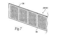
所定のハイブリッド磁性体構造物26または32の形状は解剖学的移植部位に最適適合するように選択することができる。さらに、ハイブリッド磁性体構造物26または32のいずれか一方は、内部への組織内方成長を促して移植安定性を達成するために、通し穴36(図7、参照)、および/または盲穴、および/または複雑な表面形状38(図8、参照)、および/またはその他の表面構造、またはそれらの組み合わせを備えることができる。
The shape of a given hybrid
(4.成層磁性体構造物)
磁性体構造物12および/または14は、図9に示したように、成層磁性体構造物40からなっていてよい。成層構造物40は生体適合性ポリマー24内に異なった密度で封入された2またはそれ以上の磁性粒子22の層からなっている。図9には説明のためにL1からL6までの6層が示されているが、層の数は6以上またはそれ以下とすることもできると解されなければならない。
(4. Laminated magnetic structure)
The
層L1,L3およびL5の磁性粒子22の密度は隣接する層L2,L4およびL6の磁性粒子22の密度よりも高い。低密度層L2,L4およびL6が存在することにより、構造物40の全体に柔軟性が付与され、他方、高密度層L1,L3およびL5が存在することにより、高い磁力が付与される。高密度層L1,L3およびL5の間に低密度層L2,L4およびL5が並置されていることにより、高密度層L1,L3およびL5から発する力線は、ポリマー結合された全体として均一な密度の磁性層に比較して、構造物40の表面からさらに遠くまでプッシュされる。力線のこうした変化によって漏れ磁束は減少する。
The density of the
先述したように、磁性粒子22は等方性材料または異方性材料たとえばNdFeB、SmCo、フェライトおよび/またはアルニコの粒子からなっていてよく、生体適合性ポリマー24はたとえばポリカーボネート、シリコーンゴム、ポリウレタン、シリコンエラストマまたは軟質もしくは半硬質プラスチックからなっていてよい。繊維および/またはクロスおよび/またはセラミック材料もポリマーマトリックスのうちに組み入れることができる。構造物40内において、層L1〜L6の磁性粒子22は同一磁束方向に磁化される。
As previously mentioned, the
図9において、高密度層L1,L3およびL5の磁性粒子22の密度は一般に同一として示されている。別途配置(図10、参照)において、高密度層L1,L3およびL5の磁性粒子22の密度は徐々に増加してよい。これによって、構造物40の表面全体の横断的な磁束密度の変化が達成される。
In FIG. 9, the densities of the
図2に示したシステム10において、構造物12および/または14はそれぞれ成層磁性体構造物40、または、別のタイプの磁性体構造物たとえば不連続な永久磁石の柔軟なアレイ、ポリマー結合された磁石またはハイブリッド磁性体構造物26および/または32と組み合わせて使用された成層磁性体構造物40からなっていてよい。それにもかかわらず、咽頭壁と舌とに移植された構造物12と14とは同じ極性を有し、これにより、両者の間に所望の反発力が生み出される。
In the
成層磁性体構造物40の形状は解剖学的移植部位に最適適合するように選択することができる。たとえば図11に示したように、成層構造物40は連結ストリップ46によって分離された両端部分44からなっていてよい。両端部44のそれぞれは、先に説明したように、生体適合性ポリマー24内に異なった密度で封入された磁性粒子22の層、L1〜L6を含んでいる。別法として、層L1〜L6の密度を変化させるか、または一方もしくは双方の端部44内の磁性粒子の密度を均一にすることも可能である。連結ストリップ46は磁性粒子22を含まない生体適合性ポリマー24からなっている。両端部44の磁性粒子22は同一極性を有するように磁化されることから、両端部は互いに反撥する。磁性粒子22を含んでいない中間ストリップ44は反発力を妨げることはない。
The shape of the layered
図12が示しているように、構造物40は、組織内方成長を促して移植安定性を達成するため、(盲穴Hのパターンとして示されているような)構造化された表面を有していてよい。(図7に示したような)通し穴、および/または(図8に示したような)複雑な表面形状、および/またはその他の表面構造、またはそれらの組み合わせも前記と同じ目的のために使用することができる。
As FIG. 12 shows, the
(C.磁性体構造物の磁束の集束)
移植される磁性体構造物のタイプにかかわりなく、身体によって不快感なく受け入れられる比較的小さな寸法の磁石アレイを使用して高い反発力を達成するのが好ましい。この目的を達成する一つの方途は、所望の方向へ磁束を集束させる一方で他の方向への磁束を減少させる手段を設けることである。磁束を集束させることにより、比較的小さな磁石の使用が可能になる。また、磁束を集束させることにより、移植構造物に組織内での変位に抗する安定性も付与することができる。
(C. Focusing of magnetic flux of magnetic structure)
Regardless of the type of magnetic structure being implanted, it is preferable to achieve a high repulsion force using a relatively small size magnet array that is accepted by the body without discomfort. One way to achieve this goal is to provide means to focus the magnetic flux in the desired direction while reducing the magnetic flux in the other direction. By focusing the magnetic flux, a relatively small magnet can be used. In addition, by focusing the magnetic flux, it is possible to impart stability to the transplanted structure against displacement within the tissue.
図13は、磁石コア48と、それに被装された軟強磁性材料製の磁束シールド50とを含む磁性体構造物46を示したものである。磁石コア48は、希土類永久磁石、またはポリマー結合された磁石、またはハイブリッド磁性体構造物、または成層磁性体構造物からなっていてよく、これらについてはすべて先に説明した。磁束シールド50の軟強磁性材料は非常に高い透磁率と飽和磁化とを有するが、固有保磁力は非常に低い。公知の軟強磁性材料の例を挙げれば、鉄(Fe)、ニッケル(Ni)、パーメンジュール、ミューメタル、低炭素鋼、鉄・コバルト合金(Fe−Co)、ケイ素鋼および非晶質合金である。
FIG. 13 shows a
以下の実施例が具体的に示すように、軟強磁性材料を含む磁束シールド50の存在はシールド50が遮蔽していない方向にコア48の磁界を集束させて増強する。図13において、磁束シールド50はコア48の1極を除いてすべてを被覆している。ただし、後に示すように、磁束シールド50は、磁束集束効果を達成するのに、コア48の1極表面を被覆しているだけでもよい。
As specifically shown in the following embodiments, the presence of the
(実施例1)
(無遮蔽コア)
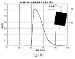
図14Aは、40mm×40mm×25mmの寸法(つまり、体積40.000mm3)を有する永久磁石を含むコア48を示したものである。図14Bは、永久磁石によって発生した磁界の、有限要素法モデリングに基づく、YZ面の総磁束密度分布を示したものである。図14Bは、磁石の周囲で磁界がYZ面の全方向に発していることを示している。図14Cは、磁石表面からの磁石中心線に沿った距離の増大に応じた、磁束密度のZ成分の大きさ(Bz)を示している。図14Cは、総じて鐘形の曲線を示しており、Bz(T)の最大値0.6は磁石表面から約62mmの距離にあり、これは距離が減少するとともに徐々に増大しかつ距離が増加するとともに徐々に減少する。
Example 1
(Unshielded core)
FIG. 14A shows a core 48 that includes a permanent magnet having dimensions of 40 mm × 40 mm × 25 mm (ie, a volume of 40.000 mm 3 ). FIG. 14B shows the total magnetic flux density distribution on the YZ plane based on the finite element method modeling of the magnetic field generated by the permanent magnet. FIG. 14B shows that the magnetic field is emitted in all directions on the YZ plane around the magnet. FIG. 14C shows the magnitude (Bz) of the Z component of the magnetic flux density as the distance along the magnet center line from the magnet surface increases. FIG. 14C shows a generally bell-shaped curve, with a maximum Bz (T) value of 0.6 at a distance of about 62 mm from the magnet surface, which gradually increases and increases with decreasing distance. Gradually decreases.
(実施例2)
(遮蔽コア)
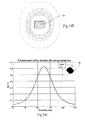
図15Aは、実施例1の磁石よりも小さい、30mm×30mm×20mmの寸法(つまり、より小さな18.000mm3の体積)を有する永久磁石を含むコア48を示している。この磁石は磁束シールド50の内部に配置されている。磁束シールドは軟強磁性材料製の箱からなっている。この箱は永久磁石の1極表面を除いて全体を被覆している。
(Example 2)
(Shielding core)
FIG. 15A shows a core 48 that includes a permanent magnet having dimensions of 30 mm × 30 mm × 20 mm (ie, a smaller volume of 18.000 mm 3 ) that is smaller than the magnet of Example 1. This magnet is disposed inside the
図15Bは、箱に収容された永久磁石によって発生した磁界の、有限要素法モデリングに基づく、YZ面の総磁束密度分布を示したものである。図15Bは、箱を形成している強磁性材料の存在によって、YZ面における磁界の磁束密度分布パターンが著しく変化させられることを示している。磁界は、強磁性材料によってシールドされていない磁界方向に明白に集束させられている。図15Cは、無遮蔽極表面からの磁石中心線に沿った距離の増大に応じた、磁束密度のZ成分の大きさ(Bz)を示している。図15Cは磁界が集束していることを裏付けている。図15Cは、また、実施例1に比較して有意に小さな体積の磁石を使用しているにもかかわらず、実施例2のZ成分の磁束密度は増大していることも示している。図14Cの曲線とは異なり、図15Cの曲線は鐘形ではない。磁束密度のZ成分は無遮蔽極表面から約55mmの距離にあるBz(T)の最大値1.2に瞬時に上昇し、その後、磁石の唯一の無遮蔽極表面から約75mmの距離に達するまで約0.6Bz(T)以上 ― つまり、実施例1のZ成分の最大磁束密度以上 ― の大きさを保っている。 FIG. 15B shows the total magnetic flux density distribution on the YZ plane based on the finite element method modeling of the magnetic field generated by the permanent magnet housed in the box. FIG. 15B shows that the magnetic flux density distribution pattern of the magnetic field in the YZ plane is significantly changed by the presence of the ferromagnetic material forming the box. The magnetic field is clearly focused in a magnetic field direction that is not shielded by the ferromagnetic material. FIG. 15C shows the magnitude (Bz) of the Z component of the magnetic flux density as the distance along the magnet center line from the unshielded pole surface increases. FIG. 15C confirms that the magnetic field is focused. FIG. 15C also shows that the magnetic flux density of the Z component of Example 2 is increased despite the use of a significantly smaller volume of magnet compared to Example 1. Unlike the curve of FIG. 14C, the curve of FIG. 15C is not bell-shaped. The Z component of the magnetic flux density rises instantaneously to a maximum Bz (T) value of 1.2 at a distance of about 55 mm from the unshielded pole surface, and then reaches a distance of about 75 mm from the only unshielded pole surface of the magnet. The size of about 0.6 Bz (T) or more, that is, the maximum magnetic flux density of the Z component of Example 1 or more is maintained.
図14B/Cと図15B/Cとの比較から、軟強磁性材料は永久磁石から発する磁界を遮蔽しかつ集束させることができるとのことを具体的に看取することができる。 From the comparison between FIG. 14B / C and FIG. 15B / C, it can be specifically observed that the soft ferromagnetic material can shield and focus the magnetic field emitted from the permanent magnet.
(実施例3)
(別途遮蔽磁石)
図16A,16Bは、軟強磁性材料製の磁束シールド50を備えた永久磁石を含む別途実施形態の磁石コア48を示したものである。これらの別途実施形態の磁石コアの有限要素法による解析は、図15Bに示した磁束密度分布の集束だけでなく、図15Cに示した、無遮蔽磁極表面からの磁石中心線に沿った距離の増大に応じた、磁束密度のZ成分(Bz)のスパイク形曲線も明らかにしている。
(Example 3)
(Separate shielding magnet)
FIGS. 16A and 16B show a
(実施例4)
(単極シールド)
図17Aは全体として実施例1の磁石と同一の寸法を有する永久磁石を含む磁石コア48を示したものである。この実施形態において、磁束シールド50は磁石の単一極しか覆っていない。図17Bは、無遮蔽磁極からの磁石中心線に沿った距離の増大に応じた磁束密度のZ成分の大きさ(Bz)は単極磁束シールド50の存在によって変化させられていることを示している。図17Bは、単極磁束シールド50の存在が無遮蔽磁極の方向に磁界を集束させていることを明確にする、図15Cに示したものと同じスパイク形曲線を示している。図17Bは、また、磁界の最大強さが同じく、実施例1の0.6Bz(T)から実施例4の0.7Bz(T)に増加したことも明確にしている。図17Bは、軟強磁性材料を含む単極磁束シールド50が永久磁石から発する磁界を遮蔽しかつ集束させることができることを具体的に示している。
Example 4
(Single pole shield)
FIG. 17A shows a
(D.磁性体構造物の不安定性の減少)
移植される磁性体構造物のタイプにかかわりなく、磁界の力に起因する不安定化効果を最小限に抑止することも望ましい。また、万一、互いに対向する磁性体構造物12と14との磁界の力の間に不整合が生じた場合にも、それに起因する変位またはねじれを最小限に抑止することも望ましい。もしも反撥する同じ磁極に不整合が生じれば、異なった磁極同士が引き合って整合しようとすることともなろう。
(D. Reduction of instability of magnetic structure)
Regardless of the type of magnetic structure being implanted, it is also desirable to minimize destabilizing effects due to magnetic field forces. In addition, in the event that a mismatch occurs between the magnetic field forces of the
不安定化効果を最小限に抑止する一つの方途は、主反撥極に対して直角または鋭角をなす反発極を有する安定化磁石を設けることである。これを説明するため、図18A,18Bは、一組の安定化磁石56と組み合わされた磁石コア54を含む安定化された磁性体構造物52を示している。
One way to minimize the destabilizing effect is to provide a stabilizing magnet having a repulsion pole that is perpendicular or acute to the main repulsion pole. To illustrate this, FIGS. 18A and 18B show a stabilized
磁石コア54は、希土類永久磁石、またはポリマー結合された磁石、またはハイブリッド磁性体構造物、または成層磁性体構造物からなっていてよく、これらについてはすべて先に説明した。磁石コア54は、所与の構造物に必要とされる反発力を基本的に供することができる寸法と構成とを有する反撥極58を有している。
The
各々の安定化磁石56は、たとえば接着、溶接、成形、圧着または半田付けによって反撥する磁石コア54の側面に固定される。安定化磁石56は、希土類永久磁石、またはポリマー結合された磁石、またはハイブリッド磁性体構造物、または成層磁性体構造物からなっていてよく、これらについてはすべて先に説明した。安定化磁石56はそれぞれ反撥極60 (つまり、反撥極58と同一の極性を有する極)を有している。安定化磁石56の反撥極60の表面は磁石コア52の反撥極58に対して直角に配向される。安定化永久磁石56の極60はすべて、磁石コア52の反撥極58と同様に、対向する磁性体構造物の磁石(単数または複数)の極と同じである。
Each stabilizing
万一、一方の磁性体構造物の回転に起因する不整合が生じても、安定化永久磁石56の外側に面する極60は、多かれ少なかれ、他方の磁性体構造物の磁石( 単数または複数)の同じ極に対向し続けることとなる。安定化永久磁石56の外側に向いた極60は他方の構造物の極と同一であることから、二つの構造物の間の磁界の反撥性は同じままであり ― 二つの磁性体構造物12と14とは互いに反撥し続ける。回転による不整合は磁力場の減少を伴い得るが、それにもかかわらず磁力場それ自体は依然として反撥場である。不整合に起因する磁界の不安定化は減少させられ、構造物12/14の一方のねじれまたはその他の不安定化も減少させられる。
In the unlikely event of misalignment due to the rotation of one magnetic structure, the
さらに図18A、18Bに示したように、安定化された磁性体構造物52は、磁石コア54の反対側の極面に固定された軟強磁性材料を含む遮蔽極片62を含んでいてよい。遮蔽極片62は、先に説明したように、図17Bに示したスパイク形動作特性を実現することにより、磁束密度のZ成分(Bz)の分布と大きさとを変化させる機能を果たす。遮蔽極片62は所望の方向へ磁束を集束させる。
Further, as shown in FIGS. 18A and 18B, the stabilized
典型的な1実施例において、反撥する磁石コア54は2mm×2mm×4mmの寸法を有し、各々の安定化磁石56の寸法は1mm×2mm×4mmであり、遮蔽極片62は4mm×4mm×0.5mmの寸法を有している。これによって生ずる構造物52は互いに組み付けられて、安定化された磁性体構造物52のアレイ64を形成することができる(図18C、参照)。各々のアレイ64において、安定化された磁性体構造物52は互いに約1mm離間させられている。有限要素法による解析が示すところによれば、約12mm離して対向させて、反撥するように配置すれば、安定化された磁性体構造物52またはアレイ64の寸法の変化に応じて増減させることのできる反発力をアレイ64の間に発生させることができる。遮蔽極片62の存在はアレイ64の間で所望の方向への磁束の集束と増大とを結果する。安定化磁石56の存在は位置的安定性をもたらし、遮蔽極片62もまた、望ましくない方向への磁束密度を減少させることによってこれに貢献する。
In one exemplary embodiment, the repelling
図18Eに示したように、アレイ64が、安定化磁石56を備える隣接磁性体構造物52を一列以上有する場合には、アレイ64の内部の、磁性体構造物52の相互対向内側面は安定化磁石56を備える必要はない。このユニットにおいて、安定化磁石56は多重並列アレイ64の外側端縁に沿って配置されている。
As shown in FIG. 18E, when the
所与の磁石アレイの位置的安定性は、安定化磁石56を使用しなくとも高めることが可能である。図18D(1)と18D(2)に示しかつまた先に述べたように、(たとえば希土類永久磁石、またはポリマー結合された磁石、またはハイブリッド磁性体構造物、または成層磁性体構造物を含む)磁石コア54は柔軟なキャリアCに沿って配置することができる。各々の磁石コア54は所与の構造物に必要とされる反発力を供することができる寸法に形成された反撥極58を有している。この種のアレイにおける位置的安定性の向上は、いずれか1個の磁石コア54の反撥極58の向きをそれに隣接するコア54の向きに対して(それぞれ図18D(1)と18D(2)に示したように)いずれかの方向に90度だけずらすことによって達成することができる。所与のアレイ内で、1もしくは複数個のコア54はこのようにしてランダムにかまたは反復して向きを変えることができる。万一、他方の磁石アレイに対する一方の磁石アレイの回転に起因する不整合が生じても、一方もしくは双方のアレイ内に向きの変えられた少なくとも1個のコアが存在することにより、多かれ少なかれ、二つの構造物の間の磁界の反発性は維持されることになる。不整合に起因する磁界の不安定性は減少させられ、いずれか一方のアレイのねじれまたはその他の不安定化も減少させられる。
The positional stability of a given magnet array can be increased without the use of stabilizing
(II. 組織内移植構造物の固定)
以上に述べたタイプまたはその他のデザインおよび機能を有するインプラントは、咽頭壁および/または舌(位置は図2に示した)、および/または咽頭管内のその他の場所、および/または体内のその他の場所にさまざまな方法で経皮的に固定することができる。以下に述べるさまざまな固定技法の説明はインプラントが磁性体構造物でありかつ移植部位が咽頭管内であることを示しているとはいえ、これらの説明はあくまでも所定の技法の特徴と利点とを説明するためのものであると理解されなければならない。以下に説明される特徴と利点とは体内のいかなる移植部位に装着されるいかなるインプラントにも広範に当てはまるものである。
(II. Fixation of transplanted structure in tissue)
Implants having the types or other designs and functions described above may be used in the pharyngeal wall and / or tongue (positions shown in FIG. 2) and / or other locations within the pharyngeal canal and / or other locations within the body. It can be fixed percutaneously in various ways. Although the following descriptions of various fixation techniques indicate that the implant is a magnetic structure and the implantation site is within the pharyngeal canal, these descriptions only explain the features and advantages of a given technique. Must be understood to be The features and advantages described below are broadly applicable to any implant that is installed at any implantation site in the body.
(A.機械的固定材料の使用)
移植された磁性体構造物12/14の位置または一般にいかなるインプラントの位置も、目標組織部域内たとえば咽頭管内での変位を防止するため、従来の機械的固定材料と外科技術において公知の技法、たとえば吸収性または非吸収性の縫合糸、ねじ固定術、ステープル法、ダーツ、クリップ、接着剤またはグルーたとえばシアノアクリル酸樹脂、またはセメントたとえばポリメチルメタクリル酸(PMMA)セメントを使用して固定することができる。たとえば構造物12/14または一般にいかなるインプラントも、固定材料たとえば縫合糸、ねじ、ステープル、ダーツまたはクリップを収容するための予備成形されたアパーチャを有していてよい。組織への固定は移植構造物の固定機能を向上させる。
(A. Use of mechanical fixing materials)
To prevent displacement of the implanted
所定のインプラントが固定される組織は軟組織、たとえば粘膜、粘膜下組織、筋膜、または咽頭壁筋、舌根、谷、軟口蓋と口蓋垂、口蓋扁桃と関連柱組織および喉頭蓋であってよい。 The tissue to which a given implant is fixed may be soft tissue, such as mucosa, submucosa, fascia or pharyngeal wall muscle, tongue base, valley, soft palate and uvula, tonsil and associated column tissue and epiglottis.
組織はまた、咽頭管内の骨たとえば舌骨または脊椎であってもよい。 The tissue may also be a bone in the pharyngeal canal, such as the hyoid bone or the spine.
組織、筋肉または骨に埋食された磁性体構造物を機械的に固定するためのさまざまなシステムは、本引証によりその内容を本願明細書に引用したものとする、2003年11月20日出願の、「体部域内たとえば咽頭管内の組織を固定するための装置、システムならびに方法」を名称とする合衆国特許出願第10/718,254号に示されている。 Various systems for mechanically fixing magnetic structures embedded in tissue, muscle or bone are hereby filed on Nov. 20, 2003, the contents of which are hereby incorporated by reference. In US patent application Ser. No. 10 / 718,254, entitled “Apparatus, System and Method for Immobilizing Tissue in a Body Area, eg, the Pharyngeal Canal”.
所定の磁性体構造物またはインプラントは、水平または垂直な解剖学的配向で、および/または直線的または曲線的なパターンで、咽頭管内またはその他の身体部位に移植することができる。 A given magnetic structure or implant can be implanted in a pharyngeal canal or other body part in a horizontal or vertical anatomical orientation and / or in a linear or curvilinear pattern.
(B.筋肉またはその他の軟組織への固定)
(1.直達手術(皮弁))
インプラントは外科的に皮弁を設けることにより、粘膜内または粘膜下組織内に、または筋膜に対し、または咽頭壁内および/または舌の筋肉に対しもしくは筋肉内に(位置は図2に示した)、またはその他の身体部位に直接に装着することができる。
(B. Fixation to muscle or other soft tissue)
(1. Direct surgery (skin flap))
The implant can be surgically provided with a flap, into the mucosa or submucosa, or to the fascia, or to the pharyngeal wall and / or to the tongue muscle or into the muscle (position shown in FIG. 2). Or can be worn directly on other body parts.
直達手術を行う場合には、粘膜を通してインプラントに達する縫合糸は不要である。縫合糸が粘膜を貫通する場合には縫合線に沿って、汚染した口腔から無菌のインプラントに達するコンジット効果が生ずることがあることが見出されている。また、皮弁法を適用する場合には、直接目視下でインプラントをよりよく安定させることが可能であり、したがって、直接目視下でインプラントをよりよくポジショニングすることができる。 When direct surgery is performed, sutures that reach the implant through the mucosa are not necessary. It has been found that if the suture penetrates the mucosa, a conduit effect can occur along the suture line from the contaminated oral cavity to the sterile implant. In addition, when applying the flap method, it is possible to better stabilize the implant under direct visual observation, and therefore, the implant can be better positioned under direct visual observation.
皮弁法は一段式または二段式で実施することができる。磁性体構造物またはその他のタイプまたは形式のインプラントを咽頭管内またはその他の身体部位に装着するには、いずれかの方式を使用することができる。 The flap method can be performed in one or two stages. Either method can be used to attach a magnetic structure or other type or form of implant in a pharyngeal canal or other body part.
(a.一段式皮弁法)
図19A〜19Dは咽頭側壁にインプラントを装着するための一段式皮弁法の適用を示した図である。図20A〜20Dは後咽頭側壁にインプラントを装着するための一段式皮弁法の適用を示した図である。図21A〜21Dは舌の後方域にインプラントを装着するための一段式皮弁法の適用を示した図である。
(A. One-stage flap method)
19A to 19D are views showing the application of a single-stage flap method for mounting an implant on the pharyngeal side wall. 20A to 20D are views showing the application of a single-stage flap method for mounting an implant on the posterior pharyngeal side wall. 21A to 21D are views showing application of the one-stage flap method for mounting an implant in the posterior region of the tongue.
口腔、側壁または舌を経口曝露した後、組織面に皮弁70が形成される(図19A,20Aおよび21A、参照)。皮弁70は所望の形状の切開を行うのに適した外科用刀を使用して形成される。形成される皮弁70は、所望の位置、形状および所期のインプラント機能に応じ、さまざまな形状とポジションを有していてよい。例を挙げれば、互いに直接に対向するインプラントを装着するために両側咽頭壁に配される皮弁70は、上下を逆さにした「L」字状に形成することができる。また、二つの後側方インプラントを装着するために、下向きまたは上向きの「U」字形の皮弁を、連結してまたは正中線をまたがずに、後咽頭壁または後咽頭側壁に形成することができる。舌にも同様に構成されて同様にして持ち上げることのできる皮弁を形成することができる。
After oral exposure of the oral cavity, sidewall or tongue, a
皮弁70を持ち上げることにより、筋膜で覆われた下層筋肉72を曝露させることができる(図19B,20Bおよび21C、参照)。インプラントを慎重に装着するためには優れた曝露が必要である。咽頭皮弁(側壁皮弁ならびに後側壁皮弁)は咽頭括約筋を曝露させ、舌皮弁は頤舌筋を曝露させることができる。
By lifting the
次いで、図19C、20Cおよび21Cに示したように、選択されたインプラント74は、たとえば単純な縫合糸76、および/またはマットレス縫合糸、および/またはステープル、および/またはクリップ、および/またはダーツ、および/または構造物の生体適合性本体に取付けもしくは形成されたフックまたはファスナ(これらは所望であれば、生分解性のものであってよい)を用いて、それぞれの持ち上げられた皮弁70内の、粘膜内または粘膜下組織内に、または筋膜に対しまたは筋肉72に対しまたは筋肉内に安定化される。インプラント74は好ましくは抗生物質に浸漬されているかまたはそれが含浸されている。後側壁皮弁(図20C、参照)の場合には、前脊柱に固定される骨アンカ78を使用することができる。
Then, as shown in FIGS. 19C, 20C, and 21C, the selected
皮弁を形成する代わりに、インプラントを収容する外科的ポケットを形成することができることも看取されなければならない。ポケットは、インプラントを収容する組織内スペースを空けるため、トロカールまたは拡張式切開用器を使用して組織を膨張させることによって形成される。ポケット法を適用する場合には、皮弁法と同様に、粘膜を通してインプラントに達する縫合糸は不要である。外科的皮弁術に関連してここに述べた移植ならびにインプラント固定技法は外科的ポケットにも適用可能である。 It should also be observed that instead of forming a flap, a surgical pocket can be formed to accommodate the implant. The pocket is formed by inflating the tissue using a trocar or an expandable dissector to make room in the tissue that houses the implant. When the pocket method is applied, the suture reaching the implant through the mucosa is not necessary, as in the flap method. The implantation and implant fixation techniques described herein in connection with surgical flap are also applicable to surgical pockets.
図19D、20Dおよび21Dに示したように、いまやインプラント74を皮弁切り口からある程度離間して安定化させた状態で、たとえば1または複数本の吸収性または非吸収性の縫合糸80、接着剤、またはグルーたとえばシアノアクリル酸樹脂、またはセメントたとえばポリメチルメタクリル酸(PMMA)セメントを使用して皮弁70(またはポケット)を閉じることができる。吸収性縫合糸80は急速に(たとえば7日間以内に)溶ける材料かまたは緩吸収性縫合糸たとえばビクリルTM材料であってよい。望ましくは、インプラントを装着する前または後に皮弁70(またはポケット)に適用することのできる補助的な浸透性抗生物質が使用される。
As shown in FIGS. 19D, 20D and 21D, the
さらなる安定化のために急速な線維形成を促す薬剤を使用することができる。この種の薬剤の例を挙げれば、フィブリンシーラント、ティシューシーラント、タルク(ドライまたはスラリ)、ドキシサイクリン、ブレオマイシン、ポビドンヨード、ミノサイクリン、ドキソルビシン、ストレプトキナーゼ、ウロキナーゼ、硫酸テトラデシル・ナトリウム、および/または硝酸銀である。インプラント74の安定性を促進するその他のコーティングは、カルシウム・ヒドロキシルアパタイト、酸化アルミニウム、バイオアクティブ・ヒドロキシルアパタイト、またはリン酸トリカルシウムである。この種の薬剤は、除去のためにインプラント74の上面に容易にアクセスすることができるように、インプラント74のプレ選択された箇所、たとえば底面および側面領域にもっぱら施すことができる。別法として、この種の薬剤は皮弁70(またはポケット)に直接に注入するかまたは皮弁70(またはポケット)を洗滌するために使用することができ、あるいは皮弁70(またはポケット)のゲルまたはヒドロゲル中に配することができる。
Agents that promote rapid fibrosis can be used for further stabilization. Examples of such drugs are fibrin sealant, tissue sealant, talc (dry or slurry), doxycycline, bleomycin, povidone iodine, minocycline, doxorubicin, streptokinase, urokinase, sodium tetradecyl sulfate and / or silver nitrate. Other coatings that promote the stability of the
組織接着剤、フィブリンシーラント、およびグルーたとえばシアノアクリル酸樹脂、またはセメントたとえばポリメチルメタクリル酸(PMMA)セメントは安定性を向上させるかまたは機械的縫合糸またはファスナに代えて使用することができる。無血管性ポケットを形成するために組織剥離剤またはエネルギ源を使用することもできる。 Tissue adhesives, fibrin sealants, and glues such as cyanoacrylate resins, or cements such as polymethylmethacrylic acid (PMMA) cement can improve stability or can be used in place of mechanical sutures or fasteners. A tissue stripper or energy source can also be used to form an avascular pocket.
後にもっと詳細に説明するように、組織内方成長材料も利用することが可能である。 As will be described in more detail later, tissue ingrowth materials can also be utilized.
(b.二段式皮弁法)
上述した技法は二段式で実施することも可能である。
(B. Two-stage flap method)
The technique described above can also be implemented in two stages.
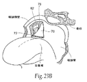
この方式(図23A、参照)において、咽頭皮弁70(側壁皮弁または後側壁皮弁)および/または舌皮弁70は、筋膜で覆われた咽頭括約筋72または頤舌筋72を曝露させる前述した方法で形成することができる。図23Aは、説明を目的として、咽頭側壁に形成された皮弁を示している。別法として、外科的ポケットが形成されてもよい。
In this manner (see FIG. 23A), the pharyngeal flap 70 (side wall flap or posterior side wall flap) and / or the
次いで、モジュール容器82またはスリーブ(図22、参照)は、吸収性または非吸収性の縫合糸、および/またはステープル、および/またはフックおよび/またはファスナ、および/またはダーツ、および/またはクリップ、および/またはねじ、および/または接着剤、および/またはグルーたとえばシアノアクリル酸樹脂、またはセメントたとえばポリメチルメタクリル酸(PMMA)セメントを用いて、それぞれの皮弁70(図23B)(またはポケット)内の、たとえば粘膜内、または筋膜に対し、または筋肉内または筋肉に対して安定化される。皮弁70(またはポケット)は、続いて、非吸収性または吸収性の縫合糸80、接着剤、またはグルーたとえばシアノアクリル酸樹脂、またはセメントたとえばポリメチルメタクリル酸(PMMA)セメントを用いて閉じられる。望ましくは補助的な浸透性抗生物質が使用される。
The
図23Cに示したように、移植された容器82は線維性カプセル形成によるかまたは組織内方成長によって皮弁またはポケット内に安定化されることができる。皮弁70またはポケット内における容器82の安定化を促進もしくは向上させるため、一段式皮弁法と同様に、薬剤を使用して組織表面の急速な線維形成を促し、および/またはティシューシーラント、接着剤、および/またはグルーを適用して安定性を向上させまたはこれらを機械的縫合糸またはファスナに代えて使用し、および/または組織剥離剤またはエネルギ源を適用して無血管性ポケットを形成し、および/または、後にもっと詳細に説明するように、組織内方成長材料を使用することができる。
As shown in FIG. 23C, the implanted
容器82が皮弁70(またはポケット)内に安定化させられた後、選択されたインプラント74が容器82内に装入される(図23D、参照)。これはたとえば皮弁またはポケットの部分再切開によるか、または経粘膜トロカールを使用して行うことができる。
After the
二段式皮弁法は、たとえば磁力またはその他の潜在的な不安定化力の作用を受けるインプラント74を手術によって導入するに先立って、皮弁またはポケット内における基本的なインプラントサポート(つまり、容器82)の安定化を可能とする。二段式皮弁法は、また、基本的なインプラントサポートを替えることなく、個々の患者のニーズに合った磁力要件の滴定を可能にする。
The two-stage flap method involves a basic implant support (ie, a container) within the flap or pocket prior to surgically introducing an
(C.器具法)
以上に述べたタイプまたはその他のデザインおよび機能を有するインプラントは、また、咽頭壁および/または舌(位置は図2に示した)または体内のその他の場所に、皮弁またはその他の切開部位を形成することなく、経皮器具システム84を使用して経皮的に装着することもできる。器具システム84はさまざまに構成することができる。
(C. Instrument method)
Implants of the type described above or other designs and functions may also form flaps or other incision sites in the pharyngeal wall and / or tongue (location shown in FIG. 2) or elsewhere in the body Alternatively, the
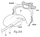
図24A〜24Cは代表的なシステム84を示したものである。システム84は、それを使用して、舌(図26A、参照)または咽頭壁(図26B、参照)の選択された移植部位に達する経皮経路をつくるために口腔内に挿し込まれるアクセスカニューレ86を含んでいる。最初に目標組織部位に穿刺するためにトロカールチップ・ガイドワイヤ90を使用することができる。次いで、カニューレに内蔵された組織面切開用器88がガイドワイヤ90に沿って進入させられて、組織への刺入口をつくり、移植部位において組織層を分離する。続いて、ガイドワイヤ90が抜き去られ、アクセスカニューレ86が移植部位まで切開用器88に沿って進入させられる。切開用器88とガイドワイヤ90は抜き取られ、こうしてアクセスカニューレ86を貫通して移植部位に達する作業路が開かれる。
24A-24C illustrate a
別法として、切開用器88とアクセスカニューレ86とは入れ子式に組み合わされて、ガイドワイヤを使用しまたは使用せずに、一つのユニットとして組織内に進入させることができる。切開用器88のチップはカニューレ86末端を越えて突き出し、刺入口を開き、移植部位において組織層を分離する機能を果たす。次いで、切開用器88がカニューレ86から抜き取られて、作業路が開かれる。
Alternatively, the dissecting
いずれかの実施形態において、もし必要であれば、インプラントを収容する組織内に外科的ポケットをつくるために、カニューレ86の作業路を通して別の器具を配することもできる。
In any embodiment, if necessary, another instrument can be placed through the working path of
図24Bに示したように、システム84はインプラント送達ツール92を含んでいてよい。ツール92はインプラント94を予圧された状態でその遠位末端に担持している。ツール92はカニューレ86の作業路を通過して移植部位に達する。プランジャ96またはロッドがインプラントに当接している。プランジャ96を定位置に保ち、ツール92を引き戻すことにより、インプラントはツール92の遠位末端から所定の移植部位に追い出される(図24C、参照)。カニューレ86とインプラント送達ツール92とは適当な時を見計らってユニットとして抜き去られ、インプラントが当該部位に残される。
As shown in FIG. 24B, the
別法として、インプラント94をカニューレ86の近位末端に直接に装入し、プランジャ96がカニューレ86を通してインプラントをカニューレ86の遠位末端まで前進させるようにすることもできる。プランジャを定位置に保ち、カニューレ86を引き戻すことにより、インプラントは所定の移植部位に追い出される。続いて、カニューレ86とプランジャ96とはユニットして抜き取られ、インプラントが当該部位に残される。
Alternatively,
図24Cに示したように、所与のインプラント94は、装入されている間、カニューレ86の作業路内または送達ツール92内において巻かれているかまたは畳まれていてよい。この方式において、インプラント94は、移植部位に着達した後にインプラント94を能動的または受動的に展開してその使用状態を再成させる材料からなっていてよい。たとえば、この材料はカニューレ86から追い出されるとインプラント94をレイフラットな使用状態または湾曲状使用状態に展開させることが可能であってよい。たとえば、この材料はばね定数を有するかまたは所望のレイフラット使用状態または湾曲状使用状態に自動的に展開する形状記憶を有するものであってよい。またこれに代えて、インプラント94は、カニューレ86から追い出された後にインプラント94を能動的に使用状態に再生する整形部材と一体にされて装入されてもよい。たとえば、インプラント94は、拡張または膨張してインプラントを扁平にするよう強制する拡張式構造物を内包していてよい。別法として、インプラント94は、直線または回転運動をインプラント94の展開運動に変換する機械的に拡張する部材を内包していてよい。
As shown in FIG. 24C, a given
図24A〜24Cにおいて、カニューレ86は円筒形状を有するものとして示されており、したがって、作業路内を通過するその他のツールも相応した形状を有している。ただし、形状は円筒状、楕円状、矩形状、またはその他の形状であってよい。図25Aと25Bに示したように、送達ツールの形状はインプラント94自体の形状に合わせてカスタマイズされてよい。たとえば、インプラント94が直線角形形状を有していれば、作業路自体の断面も、図25A〜25Cに示したように、相応して矩形であってよい。
24A-24C, the
たとえば、このユニット(図25A、参照)では、矩形カニューレ86と矩形切開用器88とが組織に着達するように操作されるコンビネーションツール98を形成している。ツール98はカニューレ86の内部に切開用器98を入れ子式に収容している。切開用器98は、組織を穿刺することのできるトロカールチップまたはブレードチップを具えた鋭い入れ子スタイレットの形を取っている。カニューレ86は、切開用器98を保持する外側スタイラスの形を取っている。コンビネーションツール98は組織を穿刺し、その後に切開用器88はカニューレ86から抜き出される。組織内部にポケットを形成する必要がある場合には、別のチップツールをカニューレ86の作業路に通して、組織層の分離を行うことができる。
For example, in this unit (see FIG. 25A), a
図25Bに示したように、矩形インプラント94は矩形送達ツール92に装入される。送達ツール92はカニューレ86の作業路を通って、移植のために用意された部位に達する。矩形プランジャ96は送達ツール92を通って前進させられ、インプラント94をツール92から移植部位に追い出す。
As shown in FIG. 25B, the
一旦着装されれば、インプラント94は下側の組織/筋肉層にさらに固定されてもされなくともよい。移植部位内において、インプラント94の位置は、先に述べたように、適切な安定化手段たとえば1もしくは複数本のステープル、および/またはクリップ、および/またはダーツ、および/または縫合糸、および/または外科用接着剤またはグルーを使用して安定化されてよい。安定化は、所望であれば、インプラントを粘膜または粘膜下組織に固定しなくとも達成することができる。インプラント94に安定化手段を配するツールはアクセスカニューレまたはインプラント送達ツールの一部に組み込まれていてよく、または、そうしたツールはそれ自体がカニューレ86の作業路を貫通させられる1または複数のツールからなっているかまたはその他のなんらかの手段によって配備される1または複数のツールからなっていてよい。
Once worn, the
カニューレ86の作業路は、また、インプラント送達に先立ってまたは送達中および送達後に、送達部位を抗生物質溶液で洗浄するために使用することもできる。抗生物質溶液は、たとえばクロロヘキサリン、カナマイシン、ベイトリル(Baytril)、セファレキシン、またはゲンタマイシンを含んでいてよい。
The working path of
システムのカニューレおよびその他のツールは、金属、プラスチック、またはセラミック材料、またはそれらの組み合わせで製造されていてよい。カニューレおよびその他のツールは、(説明を目的として図26Bに示したように)使用中に器具が屈曲またはその他の形を取れるようなフレキシブルな材料でつくられていてよい。 The system cannula and other tools may be made of metal, plastic, or ceramic materials, or combinations thereof. The cannula and other tools may be made of a flexible material that allows the instrument to bend or otherwise take shape during use (as shown in FIG. 26B for illustrative purposes).
図30Aに示したように、インプラント94は、インプラントが移植部位に追い出されると自動的にインプラントを組織に固定する一体型の安定化手段100を担持していてよい。安定化手段100はさまざまな方法でインプラントと一体化することができる。たとえば、図30Aに示したように、組織安定化手段100は、ばねと同様な特性を有するエラスチックアーム102と104の末端に担持されている。エラスチックアーム102と104とはインプラント94の両端部に取り付けられ、異なった面に装着されている。エラスチックアーム102はインプラント94の前面に取り付けられ、エラスチックアーム104はインプラント94の背面に取り付けられている。こうした装着は、第一に手段100の装着を容易にするだけでなく、インプラント94回りの安定化力を均衡させる。エラスチックアーム102と104はインプラント94の面内ないしインプラント94の面外に拡がる形状記憶プラスチック材料または金属材料でつくられていてよい。
As shown in FIG. 30A, the
エラスチックアーム102と104は、インプラント24が送達ツール92内に装入されている場合には、インプラント94に対して圧縮されて内側に折り曲げられ、内部包摂状態と称される状態で装着されている(図30C、参照)。送達ツール92の束縛から解放されると(図30Aおよび30D、参照)、アーム102と104はそのばね類似特性によりインプラント94から外側へ飛出し、外部展開状態と称される状態に達し、組織と連携する。
The
このユニット(図30B、参照)において、送達ツール92の遠位末端はインプラント94の後端縁(つまり、インプラントが装入された状態からツール92を出る際に最後となる端部)に設けられたエラスチックアーム102と整合した対向スロット106を有している。インプラント94の先端縁(つまり、インプラントが装入された状態からツール92を出る際に最初となる端部)に設けられたエラスチックアーム104はスロット106と整合していない。
In this unit (see FIG. 30B), the distal end of the
インプラント92は、エラスチックアーム102と104とが外側展開状態にある状態で、後端縁を先頭にしてツール92内に装入される。インプラントがツール92内に徐々に装入される際に、スロット106はインプラント92の後端縁に設けられたエラスチックアーム102を受け入れて通過させる。図30Bから最もよく看取し得るように、インプラント92の先端縁に設けられたエラスチックアーム104がツール92の遠位末端に当設するとほぼ同時に、インプラント92の後端縁に設けられたエラスチックアーム102はスロット104の末端108に当接する。インプラント92をさらにツール92内に装入し続けると、弾性を有するエラスチックアーム102と104は折り曲げられ、徐々に前進して内部包摂状態に達する。この場合、スロット末端108はエラスチックアーム102を圧縮して前方へそらせ、遠位末端110はエラスチックアーム104を圧縮して前方へそらせることとなる。ツール92内に完全に装入されると、ツール92の壁面がエラスチックアーム102と104を圧縮してそれらを内側包摂状態に保つことになる。
The
インプラント装着時には、プランジャ96は固定されたままとされ、ツール92が移植部位から引き離される。これによってインプラント92は、最初にその先端縁がツール92の束縛から解放される。インプラントの先端縁がツール92から出ると、アーム104は外側へ飛び出して外側展開状態を実現する(図30D、参照)。(図30Aが示すように)インプラントの後端縁がツール92から出ると、アーム102は外側へ飛び出して外側展開状態を実現する。こうして、別段の安定化ツールを配備する必要なしに、自動展開安定化手段100はインプラント94を周囲組織に固定する。
When the implant is installed, the
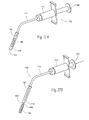
インプラントを咽頭管内またはその他の身体部位の移植部位に装着するには、その他のシステムおよび装置を使用することもできる。たとえば、図27Aと27Bは、フレキシブルチューブ116によってハンドル118と連結された送達カニューレ114を含む手持ち式ツール112を示したものである。インプラント94はカニューレ114内に保持されている。カニューレ114は針状の、組織穿通遠位チップ122を含んでいる。遠位チップ122は舌または咽頭壁の組織内に穿通され、他方、ハンドル118は全面的または部分的に口腔内に保持される。
Other systems and devices can be used to place the implant in the pharyngeal canal or other body site implantation sites. For example, FIGS. 27A and 27B illustrate a
プランジャ118はインプラント94の後端縁に当接している。プランジャ118は、(チューブ116を貫通する)プッシュプルケーブルによってハンドル114のアクチュエータ120に連結されている。アクチュエータ120を前方へ押すとプランジャ118は前進し(図27B、参照)、これによってインプラントはカニューレ114から移植部位に押し出される。
The
図28Aと28Bに示した別途実施形態において、アクチュエータ120はトリガ機構124の形を取っており、これはスライド式の後方トリガ部材126を握って定置式の前方ハンドル128に向かって押し出すか、または(鎖線で表されている)回旋式トリガ130をハンドル128に向かって引くかすることによって作動させることができる。図29Aと29Bに示した別途実施形態において、アクチュエータ120はスライド式親指操作レバー132の形を取っている。
In another embodiment shown in FIGS. 28A and 28B, the
(D. 組織内方成長面)
前述したいずれかの組織固定法に加えて、所与のインプラントは組織内方成長面70を具えることができる(図2、参照)。この種の面70の使用は先に、ポリマー結合された磁性体構造物、ハイブリッド磁性体構造物および成層磁性体構造物に関連して説明した。
(D. Organization inward growth)
In addition to any of the tissue fixation methods described above, a given implant can include a tissue ingrowth surface 70 (see FIG. 2). The use of this type of
一般に、面70は移植された構造物に接する周囲組織の内方成長を促す環境をつくり出す。組織内方成長とは移植された材料に設けられた穴が細胞性材料で充填されることとして定義される。内方成長が生ずると、移植された構造物12はしっかりと固定されるようになり、組織内での変位または組織からの押し出しに抗することとなる。こうして、組織内方成長面70は組織癒着と安定化とを向上させ、これによって、目標移植部位に移植された構造物12の位置をさらに安定化させて固定することとなる。
In general, face 70 creates an environment that encourages the ingrowth of surrounding tissue in contact with the implanted structure. Tissue ingrowth is defined as a hole in the transplanted material being filled with cellular material. When ingrowth occurs, the implanted
組織内方成長面70はさまざまな方法、たとえば材料の多孔性、編成、製織、通し穴、または多孔構造または多孔面の成形によって形成することができる。適切な材料の例を挙げれば、ポリテトラフルオロエチレン(PTFE)、発泡PTFE、ポリエチレンテトラフタレートたとえばDacron(R)(PET)クロス、その他のパーマネント・ポリエステル、ポリウレタン、シリコン、ポリプロピレンポリビニルアルコール、生分解性ポリエステルたとえばポリ乳酸およびポリグリコール酸である。
The
移植された磁性体構造物を内方成長が可能なようにして機械的に固定するのが望ましい。固定は、吸収性または非吸収性縫合糸、ねじまたはその他の、吸収性または非吸収性材料たとえばポリグリコール酸またはその他の類似の材料を含む機械的ファスナを使用して行うことができる。組織接着剤および/または組織セメントたとえばPMMAおよび/または組織シーラント、および/または組織グルーたとえばシアノアクリル酸樹脂も組織癒着、固定および安定化を実現するために使用されてよい。 It is desirable to mechanically fix the implanted magnetic structure so that it can be grown inward. The fixation can be performed using a mechanical fastener comprising an absorbent or non-absorbable suture, screw or other absorbent or non-absorbable material such as polyglycolic acid or other similar material. Tissue adhesives and / or tissue cements such as PMMA and / or tissue sealants, and / or tissue glues such as cyanoacrylate resins may also be used to achieve tissue adhesion, fixation and stabilization.
完全な組織内方成長は細胞性材料によって嵌入充填された材料のパーセンテージによって決定される。穴の寸法が100から500マイクロメートルであれば、血管が形成されることができる。穴の寸法が10から100マイクロメートルであれば、小毛細管を形成する細胞が形成されることができる。 Complete tissue ingrowth is determined by the percentage of material that is infilled with cellular material. If the hole size is 100 to 500 micrometers, blood vessels can be formed. If the hole size is 10 to 100 micrometers, cells that form small capillaries can be formed.
また、組織内方成長の有無にかかわらず、インプラント94の組織または線維による埋包を促進する材料または形状物も使用されてよい。
A material or shape that promotes the tissue or fiber embedding of the
(III. 治療提供システム)
上記から、前述した移植構造物、移植装置および外科的移植技法を基礎として、医療提供者が一連の生理的状態を非常に効果的に治療し得るようにする多用なシステムを創作し得ることが明らかである。
(III. Treatment providing system)
From the above, it is possible to create a versatile system that enables healthcare providers to treat a range of physiological conditions very effectively, based on the previously described implant structures, implant devices and surgical implantation techniques. it is obvious.
たとえば、図31に示したように、咽頭管を襲う機能不全たとえば睡眠時呼吸障害、いびき、または睡眠時無呼吸の治療を提供し得るシステム200を利用することが可能である。所望の1実施形態において、システム200はインプラント構成部202とインプランテーション構成部204とを含むことになろう。
For example, as shown in FIG. 31, it is possible to utilize a system 200 that can provide a treatment for a malfunction that attacks the pharyngeal canal, such as sleep breathing disorder, snoring, or sleep apnea. In one desired embodiment, the system 200 will include an
インプラント構成部202は、咽頭管内の少なくとも1つの咽頭構造物または少なくとも1つの解剖学的要素を含む目標組織部域に移植さるべき寸法と構成とを有する1または複数のインプラント206の提供を内実としていてよい。こうした特徴を有するインプラント206のいくつかの実施形態は本願明細書に説明した。その他の代表的な実施形態は、本引証によりその内容を本願明細書に引用したものとする、2003年11月20日出願の、「身体部域内たとえば咽頭管内の組織を固定するための装置、システムならびに方法」を名称とする合衆国特許出願第10/781,254号、2003年9月6日出願の、「咽頭管内の組織虚脱に抗するための磁力装置、システムならびに方法」を名称とする合衆国特許出願第10/656,861号、2002年9月6日出願の、「上気道系の組織を運動および/または抑制するためのシステムならびに方法」を名称とする合衆国特許出願第10/236,455号、2003年1月22日出願の、「閉塞型睡眠時無呼吸における上気道虚脱の治療のための磁気副子装置ならびに方法」を名称とする合衆国仮特許出願第60/441,639号および2003年3月20日出願の、「いびきおよび睡眠時無呼吸を含む睡眠関連呼吸障害を治療するための装置ならびに方法」を名称とする合衆国仮特許出願第60/456,164号に記載されている。
The
システム200は望ましくは、咽頭管の動的組織環境にインプラント206を装着する際に生ずる一連の課題に対処するために、インプランテーション構成部204を含んでいる。インプランテーション構成部204は、たとえば本願明細書に説明しかつ図24から30までに示したツールを使用し経皮アクセス通路を通して、または本願明細書に説明しかつ図19から23までに示したように外科的皮弁を形成することにより、または本願明細書にも説明したように外科的ポケットを形成することにより、組織部域にインプラント206を装着するための少なくとも1つのツール208および/または指示書210の提供を内実としている。
The system 200 desirably includes an
インプランテーション構成部204は、また、本願明細書に説明したように、粘膜内または粘膜下組織内に、または筋膜に対し、または筋肉に対しもしくは筋肉内にインプラントを安定化するための少なくとも1つのツール212および/または指示書214の提供を内実としていてもよい。別法として、ツール212および/または指示書214は、本願明細書に説明したように、粘膜を通して安定化するのではなく、粘膜下組織または筋膜に対し、または筋肉に対してもしくは筋肉内にインプラントを安定化させることを可能にすることができる。また、たとえば(本願明細書に説明したように)さまざまな機械的固定材料を使用し得るようにするために、または(本願明細書に説明したように)急速な線維形成を促す薬剤を利用し得るようにするために、または(本願明細書に説明したように)抗生物質材料を供するためにその他のツールおよび指示書も提供されてよい。
The
システム200の基本的な構成部202と204とは個別に提供されるかまたは、図31に示したように、キット216の形で一括されることができる。各種指示書は、キット216に含めてかつ/または臨床医のためのトレーニングプログラムまたはウェブサイトの一部として提供可能な、書面の形、電子文書の形または音声の形であってよい。
The
本発明の上述した実施形態は単に発明の原理を説明するためのものにすぎず、本発明はそれらに制限されるものではない。それに代えて本発明の範囲は、同等なものを含め、以下の請求項の範囲によって定められる。 The above-described embodiments of the present invention are merely illustrative of the principles of the invention, and the present invention is not limited thereto. Instead, the scope of the invention is defined by the following claims, including equivalents.
Claims (44)
Applications Claiming Priority (4)
| Application Number | Priority Date | Filing Date | Title |
|---|---|---|---|
| US45616403P | 2003-03-20 | 2003-03-20 | |
| US10/656,861 US7188627B2 (en) | 2002-09-06 | 2003-09-06 | Magnetic force devices, systems, and methods for resisting tissue collapse within the pharyngeal conduit |
| US10/718,254 US7360542B2 (en) | 2002-09-06 | 2003-11-20 | Devices, systems, and methods to fixate tissue within the regions of body, such as the pharyngeal conduit |
| PCT/US2004/008635 WO2004084709A2 (en) | 2003-03-20 | 2004-03-22 | Devices, systems, and methods to fixate tissue within the regions of body, such as the pharyngeal conduit |
Related Child Applications (1)
| Application Number | Title | Priority Date | Filing Date |
|---|---|---|---|
| JP2007075609A Division JP2007229485A (en) | 2003-03-20 | 2007-03-22 | Device, system, and method to fixate or support tissue within targeted region of the body, such as pharyngeal conduit for treatment of sleep disordered breathing including obstructive sleep apnea |
Publications (2)
| Publication Number | Publication Date |
|---|---|
| JP2006523121A true JP2006523121A (en) | 2006-10-12 |
| JP2006523121A5 JP2006523121A5 (en) | 2007-07-05 |
Family
ID=33102169
Family Applications (2)
| Application Number | Title | Priority Date | Filing Date |
|---|---|---|---|
| JP2006507427A Pending JP2006523121A (en) | 2003-03-20 | 2004-03-22 | Apparatus, system, and method for securing or supporting tissue within a target body region, such as a pharyngeal canal, for the treatment of sleep disordered breathing, including obstructive sleep apnea |
| JP2007075609A Pending JP2007229485A (en) | 2003-03-20 | 2007-03-22 | Device, system, and method to fixate or support tissue within targeted region of the body, such as pharyngeal conduit for treatment of sleep disordered breathing including obstructive sleep apnea |
Family Applications After (1)
| Application Number | Title | Priority Date | Filing Date |
|---|---|---|---|
| JP2007075609A Pending JP2007229485A (en) | 2003-03-20 | 2007-03-22 | Device, system, and method to fixate or support tissue within targeted region of the body, such as pharyngeal conduit for treatment of sleep disordered breathing including obstructive sleep apnea |
Country Status (6)
| Country | Link |
|---|---|
| US (1) | US7360542B2 (en) |
| EP (1) | EP1613251B1 (en) |
| JP (2) | JP2006523121A (en) |
| AU (1) | AU2004224331A1 (en) |
| CA (1) | CA2519154A1 (en) |
| WO (1) | WO2004084709A2 (en) |
Cited By (4)
| Publication number | Priority date | Publication date | Assignee | Title |
|---|---|---|---|---|
| JP2007229485A (en) * | 2003-03-20 | 2007-09-13 | Apneon Inc | Device, system, and method to fixate or support tissue within targeted region of the body, such as pharyngeal conduit for treatment of sleep disordered breathing including obstructive sleep apnea |
| JP2010508889A (en) * | 2006-11-03 | 2010-03-25 | コーニンクレッカ フィリップス エレクトロニクス エヌ ヴィ | Apparatus, system and method having movable ferromagnetic structure |
| JP2010508893A (en) * | 2006-11-03 | 2010-03-25 | コーニンクレッカ フィリップス エレクトロニクス エヌ ヴィ | Device, system and method using magnetic system affecting tongue or hyoid muscle in upper airway |
| JP2010530275A (en) * | 2007-06-18 | 2010-09-09 | コーニンクレッカ フィリップス エレクトロニクス エヌ ヴィ | Implantable device, system and method for maintaining desired orientation in a target tissue region |
Families Citing this family (170)
| Publication number | Priority date | Publication date | Assignee | Title |
|---|---|---|---|---|
| US20040267349A1 (en) * | 2003-06-27 | 2004-12-30 | Kobi Richter | Amorphous metal alloy medical devices |
| US8382821B2 (en) | 1998-12-03 | 2013-02-26 | Medinol Ltd. | Helical hybrid stent |
| US7419949B2 (en) * | 2001-07-16 | 2008-09-02 | Novo Noridsk Healthcare A/G | Single-dose administration of factor VIIa |
| US7017582B2 (en) * | 2002-02-04 | 2006-03-28 | Restore Medical Inc. | Stiffening pharyngeal wall treatment |
| US7146981B2 (en) * | 2002-02-04 | 2006-12-12 | Restore Medical, Inc. | Pharyngeal wall treatment |
| US8505539B2 (en) * | 2002-09-06 | 2013-08-13 | Koninklijke Philips N.V. | Devices, systems and methods using titrated magnetic force systems |
| US8047206B2 (en) * | 2002-09-06 | 2011-11-01 | Koninklijke Philips Electronics N.V. | Magnetic devices, systems, and methods placed in or on a tongue |
| US8590537B2 (en) | 2002-09-06 | 2013-11-26 | Koninklijke Philips N.V. | Devices, systems and methods using magnetic force systems in the tongue |
| CA2500855A1 (en) * | 2002-10-04 | 2004-04-22 | Stephen N. Brooks | System and method for preventing closure of passageways |
| US7965719B2 (en) * | 2002-12-11 | 2011-06-21 | Broadcom Corporation | Media exchange network supporting multiple broadband network and service provider infrastructures |
| US9155639B2 (en) | 2009-04-22 | 2015-10-13 | Medinol Ltd. | Helical hybrid stent |
| US9039755B2 (en) | 2003-06-27 | 2015-05-26 | Medinol Ltd. | Helical hybrid stent |
| US20050154412A1 (en) * | 2003-09-19 | 2005-07-14 | Restore Medical, Inc. | Airway implant and delivery tool |
| US7237554B2 (en) * | 2003-10-31 | 2007-07-03 | Restore Medical, Inc. | Airway implant |
| US7213599B2 (en) * | 2003-10-31 | 2007-05-08 | Restore Medical, Inc. | Airway implant |
| WO2005046554A2 (en) * | 2003-11-05 | 2005-05-26 | Pavad Medical, Inc. | Altering the stiffness, size, and/or shape of tissues for breathing disorders and other conditions |
| CA2545651A1 (en) * | 2003-11-20 | 2005-06-09 | Apneon, Inc. | Devices systems, and methods to fixate tissue within the regions of the body, such as the pharyngeal conduit |
| US8080014B2 (en) | 2004-12-15 | 2011-12-20 | Koninklijke Philips Electronics N.V. | System and method for hyoidplasty |
| US7955357B2 (en) | 2004-07-02 | 2011-06-07 | Ellipse Technologies, Inc. | Expandable rod system to treat scoliosis and method of using the same |
| US7285087B2 (en) * | 2004-07-15 | 2007-10-23 | Micardia Corporation | Shape memory devices and methods for reshaping heart anatomy |
| US7882842B2 (en) | 2004-09-21 | 2011-02-08 | Pavad Medical, Inc. | Airway implant sensors and methods of making and using the same |
| US8578937B2 (en) | 2004-09-21 | 2013-11-12 | Medtronic Xomed, Inc. | Smart mandibular repositioning system |
| US8336553B2 (en) | 2004-09-21 | 2012-12-25 | Medtronic Xomed, Inc. | Auto-titration of positive airway pressure machine with feedback from implantable sensor |
| US7980248B2 (en) * | 2004-09-21 | 2011-07-19 | Hegde Anant V | Delivery tools for sleep disorders treatment implant and methods of implantation |
| US20090038623A1 (en) * | 2004-09-21 | 2009-02-12 | Pavad Medical, Inc. | Inductive power transfer system for palatal implant |
| US20090078275A1 (en) * | 2004-09-21 | 2009-03-26 | Pavad Medical, Inc. | Palatal Implant Fixation Devices and Methods |
| US20070144535A1 (en) * | 2004-09-21 | 2007-06-28 | Hegde Anant V | Implant for treatment of sleep disorders |
| US7836888B2 (en) * | 2004-09-21 | 2010-11-23 | Pavad Medical, Incorporated | Airway implant and methods of making and using |
| US8813753B2 (en) | 2004-09-21 | 2014-08-26 | Medtronic Xomed, Inc. | Implantable obstructive sleep apnea sensor |
| US7997266B2 (en) * | 2004-10-04 | 2011-08-16 | Koninklijke Philips Electronics N.V. | System and method for airway manipulation |
| DE102005000702B4 (en) * | 2005-01-04 | 2007-08-23 | Klinikum Der Universität Regensburg | Device for central implantation in a tongue body |
| DE602006013946D1 (en) | 2005-02-08 | 2010-06-10 | Koninkl Philips Electronics Nv | SYSTEM FOR PERCUTANEOUS GLOSSOPLASTICS |
| US8371307B2 (en) | 2005-02-08 | 2013-02-12 | Koninklijke Philips Electronics N.V. | Methods and devices for the treatment of airway obstruction, sleep apnea and snoring |
| US8096303B2 (en) | 2005-02-08 | 2012-01-17 | Koninklijke Philips Electronics N.V | Airway implants and methods and devices for insertion and retrieval |
| US7322356B2 (en) * | 2005-02-24 | 2008-01-29 | Restore Medical, Inc. | Combination sleep apnea treatment |
| US9265489B2 (en) * | 2005-04-04 | 2016-02-23 | The Regents Of The University Of California | Swallow expansion device |
| AU2006231653A1 (en) * | 2005-04-04 | 2006-10-12 | The Regents Of The University Of California | Passage expansion device for patients |
| US7337781B2 (en) * | 2005-04-15 | 2008-03-04 | Restore Medical, Inc. | Implant for tongue |
| US20060235380A1 (en) * | 2005-04-15 | 2006-10-19 | Restore Medical, Inc. | Tissue incision tool |
| US7644714B2 (en) | 2005-05-27 | 2010-01-12 | Apnex Medical, Inc. | Devices and methods for treating sleep disorders |
| WO2007064908A2 (en) * | 2005-11-30 | 2007-06-07 | The Board Of Trustees Of The Leland Stanford Junior University | A system to prevent airway obstruction |
| US7909037B2 (en) | 2006-04-20 | 2011-03-22 | Pavad Medical | Tethered airway implants and methods of using the same |
| US20090173351A1 (en) * | 2006-04-20 | 2009-07-09 | Pavad Medical, Inc. | Control system for a tongue stabilization device |
| US7909038B2 (en) | 2006-04-20 | 2011-03-22 | Pavad Medical, Inc. | Tongue stabilization device and methods of using the same |
| US8256425B2 (en) | 2006-04-20 | 2012-09-04 | Medtronic Xomed, Inc. | Methods and devices for removal of a tongue stabilization device |
| US7806900B2 (en) | 2006-04-26 | 2010-10-05 | Illuminoss Medical, Inc. | Apparatus and methods for delivery of reinforcing materials to bone |
| WO2007127255A2 (en) | 2006-04-26 | 2007-11-08 | Illuminoss Medical, Inc. | Apparatus and methods for reinforcing bone |
| WO2007134005A1 (en) * | 2006-05-15 | 2007-11-22 | Mayo Foundation For Medical Education And Research | Devices and methods to treat nasal passages |
| US8517028B2 (en) * | 2006-06-23 | 2013-08-27 | Medtronic Xomed, Inc. | Stiffening procedure for sleep apnea |
| US7877142B2 (en) * | 2006-07-05 | 2011-01-25 | Micardia Corporation | Methods and systems for cardiac remodeling via resynchronization |
| JP2010502310A (en) | 2006-08-30 | 2010-01-28 | ディヴィッド・ウィリアム・スミス | Method for imparting uniaxial or multiaxial rigidity to extruded material and product obtained by the method |
| US20080078411A1 (en) * | 2006-10-03 | 2008-04-03 | Restore Medical, Inc. | Tongue implant for sleep apnea |
| US20080078412A1 (en) * | 2006-10-03 | 2008-04-03 | Restore Medical, Inc. | Tongue implant |
| US7862502B2 (en) | 2006-10-20 | 2011-01-04 | Ellipse Technologies, Inc. | Method and apparatus for adjusting a gastrointestinal restriction device |
| US20080097517A1 (en) | 2006-10-23 | 2008-04-24 | Webtec Converting, Llc. | External Nasal Dilator and Methods of Manufacture |
| US20080108860A1 (en) * | 2006-11-02 | 2008-05-08 | Bell Stephen G | Methods and Apparatus for Magnetic Manipulation or Retrieval |
| US7811284B2 (en) | 2006-11-10 | 2010-10-12 | Illuminoss Medical, Inc. | Systems and methods for internal bone fixation |
| US7879041B2 (en) | 2006-11-10 | 2011-02-01 | Illuminoss Medical, Inc. | Systems and methods for internal bone fixation |
| US9757585B2 (en) * | 2007-06-05 | 2017-09-12 | P Tech, Llc | Magnetic joint implant |
| US7658192B2 (en) * | 2007-07-03 | 2010-02-09 | Douglas C. Harrington | Method and device for treatment of obstructive sleep apnea |
| EP2131801B1 (en) * | 2007-10-19 | 2011-04-13 | Jürgen Schmitt-Bylandt | System for mandibular protrusion to prevent snoring and apnea |
| US20090112262A1 (en) | 2007-10-30 | 2009-04-30 | Scott Pool | Skeletal manipulation system |
| US9427289B2 (en) | 2007-10-31 | 2016-08-30 | Illuminoss Medical, Inc. | Light source |
| US20090165803A1 (en) * | 2007-11-01 | 2009-07-02 | Pavad Medical | On-off implant for supporting the tongue |
| US20090173352A1 (en) * | 2007-11-01 | 2009-07-09 | Pavad Medical | On-off implant for supporting the airway |
| US8403968B2 (en) | 2007-12-26 | 2013-03-26 | Illuminoss Medical, Inc. | Apparatus and methods for repairing craniomaxillofacial bones using customized bone plates |
| US8167787B2 (en) | 2008-01-03 | 2012-05-01 | Revent Medical, Inc. | Partially erodable systems for treatment of obstructive sleep apnea |
| US11202707B2 (en) | 2008-03-25 | 2021-12-21 | Nuvasive Specialized Orthopedics, Inc. | Adjustable implant system |
| US20090248148A1 (en) | 2008-03-25 | 2009-10-01 | Ellipse Technologies, Inc. | Systems and methods for adjusting an annuloplasty ring with an integrated magnetic drive |
| US7954494B1 (en) | 2008-03-26 | 2011-06-07 | Connor Robert A | Device with actively-moving members that hold or move the tongue |
| US9510922B2 (en) | 2010-05-21 | 2016-12-06 | Revent Medical, Inc. | Systems and methods for treatment of sleep apnea |
| US9439801B2 (en) | 2012-06-29 | 2016-09-13 | Revent Medical, Inc. | Systems and methods for treatment of sleep apnea |
| EP2291152A4 (en) | 2008-05-12 | 2015-05-06 | Revent Medical Inc | Partially erodable systems for treatment of obstructive sleep apnea |
| US8425527B2 (en) | 2008-07-07 | 2013-04-23 | Medtronic Xomed, Inc. | Cavitation depth, perforation confirmation and implant delivery tool |
| US8678008B2 (en) * | 2008-07-30 | 2014-03-25 | Ethicon, Inc | Methods and devices for forming an auxiliary airway for treating obstructive sleep apnea |
| US8556797B2 (en) * | 2008-07-31 | 2013-10-15 | Ethicon, Inc. | Magnetic implants for treating obstructive sleep apnea and methods therefor |
| US8413661B2 (en) | 2008-08-14 | 2013-04-09 | Ethicon, Inc. | Methods and devices for treatment of obstructive sleep apnea |
| US11241257B2 (en) | 2008-10-13 | 2022-02-08 | Nuvasive Specialized Orthopedics, Inc. | Spinal distraction system |
| US8561616B2 (en) | 2008-10-24 | 2013-10-22 | Ethicon, Inc. | Methods and devices for the indirect displacement of the hyoid bone for treating obstructive sleep apnea |
| US8561617B2 (en) | 2008-10-30 | 2013-10-22 | Ethicon, Inc. | Implant systems and methods for treating obstructive sleep apnea |
| US8382756B2 (en) | 2008-11-10 | 2013-02-26 | Ellipse Technologies, Inc. | External adjustment device for distraction device |
| IT1394518B1 (en) * | 2008-11-11 | 2012-07-05 | Gemini Group S R L | COMBINED THERAPY DEVICE WITH MAGNETS TECHNIQUE |
| US8800567B2 (en) | 2008-12-01 | 2014-08-12 | Ethicon, Inc. | Implant systems and methods for treating obstructive sleep apnea |
| US8783258B2 (en) | 2008-12-01 | 2014-07-22 | Ethicon, Inc. | Implant systems and methods for treating obstructive sleep apnea |
| CA2746218A1 (en) * | 2008-12-09 | 2010-06-17 | H-Medical | Apparatus, systems, and methods for constraining and/or supporting tissue structures along an airway |
| US8371308B2 (en) | 2009-02-17 | 2013-02-12 | Ethicon, Inc. | Magnetic implants and methods for treating an oropharyngeal condition |
| US8555891B2 (en) * | 2009-02-18 | 2013-10-15 | Medtronic Xomed, Inc. | Implant system for controlling airway passage |
| US8197490B2 (en) | 2009-02-23 | 2012-06-12 | Ellipse Technologies, Inc. | Non-invasive adjustable distraction system |
| US8307831B2 (en) | 2009-03-16 | 2012-11-13 | Ethicon, Inc. | Implant systems and methods for treating obstructive sleep apnea |
| US8210729B2 (en) | 2009-04-06 | 2012-07-03 | Illuminoss Medical, Inc. | Attachment system for light-conducting fibers |
| US8512338B2 (en) | 2009-04-07 | 2013-08-20 | Illuminoss Medical, Inc. | Photodynamic bone stabilization systems and methods for reinforcing bone |
| US9622792B2 (en) | 2009-04-29 | 2017-04-18 | Nuvasive Specialized Orthopedics, Inc. | Interspinous process device and method |
| US8870965B2 (en) | 2009-08-19 | 2014-10-28 | Illuminoss Medical, Inc. | Devices and methods for bone alignment, stabilization and distraction |
| DK2473116T3 (en) | 2009-09-04 | 2020-01-27 | Nuvasive Specialized Orthopedics Inc | Bone Growth Facilities |
| US10172669B2 (en) | 2009-10-09 | 2019-01-08 | Ethicon Llc | Surgical instrument comprising an energy trigger lockout |
| US9326886B2 (en) | 2009-10-29 | 2016-05-03 | Ethicon, Inc. | Fluid filled implants for treating obstructive sleep apnea |
| US9877862B2 (en) | 2009-10-29 | 2018-01-30 | Ethicon, Inc. | Tongue suspension system with hyoid-extender for treating obstructive sleep apnea |
| US9974683B2 (en) * | 2009-10-30 | 2018-05-22 | Ethicon, Inc. | Flexible implants having internal volume shifting capabilities for treating obstructive sleep apnea |
| US8632488B2 (en) * | 2009-12-15 | 2014-01-21 | Ethicon, Inc. | Fluid filled implants for treating medical conditions |
| WO2011116382A2 (en) | 2010-03-19 | 2011-09-22 | Revent Medical Inc. | Systems and methods for treatment of sleep apnea |
| JP2013521952A (en) | 2010-03-19 | 2013-06-13 | レベント メディカル インコーポレイテッド | Sleep apnea treatment system and method |
| GB2480498A (en) | 2010-05-21 | 2011-11-23 | Ethicon Endo Surgery Inc | Medical device comprising RF circuitry |
| US8684965B2 (en) | 2010-06-21 | 2014-04-01 | Illuminoss Medical, Inc. | Photodynamic bone stabilization and drug delivery systems |
| US9248043B2 (en) | 2010-06-30 | 2016-02-02 | Ellipse Technologies, Inc. | External adjustment device for distraction device |
| AU2011286287A1 (en) | 2010-07-26 | 2013-02-14 | Revent Medical, Inc. | Systems and methods for treatment of sleep apnea |
| WO2012021378A2 (en) | 2010-08-09 | 2012-02-16 | Ellipse Technologies, Inc. | Maintenance feature in magnetic implant |
| US8844537B1 (en) | 2010-10-13 | 2014-09-30 | Michael T. Abramson | System and method for alleviating sleep apnea |
| WO2012088432A1 (en) | 2010-12-22 | 2012-06-28 | Illuminoss Medical, Inc. | Systems and methods for treating conditions and diseases of the spine |
| WO2012112396A2 (en) | 2011-02-14 | 2012-08-23 | Ellipse Technologies, Inc. | Device and method for treating fractured bones |
| EP2731561B1 (en) | 2011-07-14 | 2016-03-23 | Cook Medical Technologies LLC | A sling to be used in the treatment of obstructive sleep apnea |
| JP2014533965A (en) | 2011-07-19 | 2014-12-18 | イルミンオス・メディカル・インコーポレイテッドIlluminOss Medical, Inc. | Apparatus and method for bone reconstruction and stabilization |
| US8905033B2 (en) | 2011-09-28 | 2014-12-09 | Ethicon, Inc. | Modular tissue securement systems |
| US10743794B2 (en) | 2011-10-04 | 2020-08-18 | Nuvasive Specialized Orthopedics, Inc. | Devices and methods for non-invasive implant length sensing |
| WO2013059609A1 (en) | 2011-10-19 | 2013-04-25 | Illuminoss Medical, Inc. | Systems and methods for joint stabilization |
| US9161855B2 (en) | 2011-10-24 | 2015-10-20 | Ethicon, Inc. | Tissue supporting device and method |
| WO2013062978A2 (en) | 2011-10-24 | 2013-05-02 | Ethicon Endo-Surgery, Inc. | Medical instrument |
| US10016220B2 (en) | 2011-11-01 | 2018-07-10 | Nuvasive Specialized Orthopedics, Inc. | Adjustable magnetic devices and methods of using same |
| US8973582B2 (en) | 2011-11-30 | 2015-03-10 | Ethicon, Inc. | Tongue suspension device and method |
| US10470760B2 (en) | 2011-12-08 | 2019-11-12 | Ethicon, Inc. | Modified tissue securement fibers |
| US9173766B2 (en) | 2012-06-01 | 2015-11-03 | Ethicon, Inc. | Systems and methods to treat upper pharyngeal airway of obstructive sleep apnea patients |
| US20130338714A1 (en) | 2012-06-15 | 2013-12-19 | Arvin Chang | Magnetic implants with improved anatomical compatibility |
| US8939977B2 (en) | 2012-07-10 | 2015-01-27 | Illuminoss Medical, Inc. | Systems and methods for separating bone fixation devices from introducer |
| WO2014189540A1 (en) | 2012-10-16 | 2014-11-27 | Catalano Peter J | Method and apparatus for treating obstructive sleep apnea (osa) |
| US9044281B2 (en) | 2012-10-18 | 2015-06-02 | Ellipse Technologies, Inc. | Intramedullary implants for replacing lost bone |
| EP2911616B1 (en) | 2012-10-29 | 2020-10-07 | NuVasive Specialized Orthopedics, Inc. | Adjustable devices for treating arthritis of the knee |
| US9687281B2 (en) | 2012-12-20 | 2017-06-27 | Illuminoss Medical, Inc. | Distal tip for bone fixation devices |
| US9179938B2 (en) | 2013-03-08 | 2015-11-10 | Ellipse Technologies, Inc. | Distraction devices and method of assembling the same |
| US10123900B2 (en) | 2013-03-15 | 2018-11-13 | Cook Medical Technologies Llc | Devices, kits, and methods for the treatment of obstructive sleep apnea |
| US10226242B2 (en) | 2013-07-31 | 2019-03-12 | Nuvasive Specialized Orthopedics, Inc. | Noninvasively adjustable suture anchors |
| WO2015017749A1 (en) | 2013-08-01 | 2015-02-05 | Mohan P Arun | Tissue adjustment implant |
| WO2015020953A1 (en) | 2013-08-05 | 2015-02-12 | Darin Schaeffer | Medical devices having a releasable tubular member and methods of using the same |
| US9801734B1 (en) | 2013-08-09 | 2017-10-31 | Nuvasive, Inc. | Lordotic expandable interbody implant |
| US10751094B2 (en) | 2013-10-10 | 2020-08-25 | Nuvasive Specialized Orthopedics, Inc. | Adjustable spinal implant |
| CN104906682A (en) | 2014-01-24 | 2015-09-16 | 史蒂文·沙勒布瓦 | Articulating balloon catheter and method for using the same |
| CN111345867A (en) | 2014-04-28 | 2020-06-30 | 诺威适骨科专科公司 | Remote control device |
| US9974563B2 (en) | 2014-05-28 | 2018-05-22 | Cook Medical Technologies Llc | Medical devices having a releasable member and methods of using the same |
| US9913661B2 (en) | 2014-08-04 | 2018-03-13 | Cook Medical Technologies Llc | Medical devices having a releasable tubular member and methods of using the same |
| JP6672289B2 (en) | 2014-10-23 | 2020-03-25 | ニューベイシブ スペシャライズド オーソペディックス,インコーポレイテッド | Teleadjustable interactive bone remodeling implant |
| CN105748187B (en) * | 2014-12-19 | 2017-12-01 | 张湘民 | Lateral wall of pharynx draw-gear and method for implantation |
| US10159524B2 (en) | 2014-12-22 | 2018-12-25 | Ethicon Llc | High power battery powered RF amplifier topology |
| EP4005515B1 (en) | 2014-12-26 | 2024-07-24 | NuVasive Specialized Orthopedics, Inc. | Systems for distraction |
| WO2016134326A2 (en) | 2015-02-19 | 2016-08-25 | Nuvasive, Inc. | Systems and methods for vertebral adjustment |
| US10314638B2 (en) | 2015-04-07 | 2019-06-11 | Ethicon Llc | Articulating radio frequency (RF) tissue seal with articulating state sensing |
| AU2016303791A1 (en) * | 2015-08-03 | 2018-02-15 | Oventus Medical Limited | Breathing assistance apparatus |
| US10959771B2 (en) | 2015-10-16 | 2021-03-30 | Ethicon Llc | Suction and irrigation sealing grasper |
| BR112018007347A2 (en) | 2015-10-16 | 2018-10-23 | Nuvasive Specialized Orthopedics, Inc. | adjustable devices for the treatment of knee arthritis |
| JP6953409B2 (en) | 2015-12-10 | 2021-10-27 | ニューベイシブ スペシャライズド オーソペディックス,インコーポレイテッド | External adjustment device for extension device |
| US10959806B2 (en) | 2015-12-30 | 2021-03-30 | Ethicon Llc | Energized medical device with reusable handle |
| WO2017132646A1 (en) | 2016-01-28 | 2017-08-03 | Nuvasive Specialized Orthopedics, Inc. | Systems for bone transport |
| WO2017139548A1 (en) | 2016-02-10 | 2017-08-17 | Nuvasive Specialized Orthopedics, Inc. | Systems and methods for controlling multiple surgical variables |
| US10856934B2 (en) | 2016-04-29 | 2020-12-08 | Ethicon Llc | Electrosurgical instrument with electrically conductive gap setting and tissue engaging members |
| US10987156B2 (en) | 2016-04-29 | 2021-04-27 | Ethicon Llc | Electrosurgical instrument with electrically conductive gap setting member and electrically insulative tissue engaging members |
| US10751117B2 (en) | 2016-09-23 | 2020-08-25 | Ethicon Llc | Electrosurgical instrument with fluid diverter |
| US11033325B2 (en) | 2017-02-16 | 2021-06-15 | Cilag Gmbh International | Electrosurgical instrument with telescoping suction port and debris cleaner |
| US10799284B2 (en) | 2017-03-15 | 2020-10-13 | Ethicon Llc | Electrosurgical instrument with textured jaws |
| US11497546B2 (en) | 2017-03-31 | 2022-11-15 | Cilag Gmbh International | Area ratios of patterned coatings on RF electrodes to reduce sticking |
| US10603117B2 (en) | 2017-06-28 | 2020-03-31 | Ethicon Llc | Articulation state detection mechanisms |
| EP3644911A1 (en) | 2017-06-29 | 2020-05-06 | Cook Medical Technologies, LLC | Implantable medical devices for tissue repositioning |
| US11484358B2 (en) | 2017-09-29 | 2022-11-01 | Cilag Gmbh International | Flexible electrosurgical instrument |
| US11033323B2 (en) | 2017-09-29 | 2021-06-15 | Cilag Gmbh International | Systems and methods for managing fluid and suction in electrosurgical systems |
| US11490951B2 (en) | 2017-09-29 | 2022-11-08 | Cilag Gmbh International | Saline contact with electrodes |
| US11071572B2 (en) | 2018-06-27 | 2021-07-27 | Illuminoss Medical, Inc. | Systems and methods for bone stabilization and fixation |
| WO2020104994A1 (en) * | 2018-11-23 | 2020-05-28 | Hnp Mikrosysteme Gmbh | Sealing structure for a transport device having a shape-memory alloy |
| EP3922039A1 (en) | 2019-02-07 | 2021-12-15 | NuVasive Specialized Orthopedics, Inc. | Ultrasonic communication in medical devices |
| US11589901B2 (en) | 2019-02-08 | 2023-02-28 | Nuvasive Specialized Orthopedics, Inc. | External adjustment device |
| US20230007905A1 (en) | 2019-12-10 | 2023-01-12 | Medartis Holding Ag | Apparatus and method for piercing a soft tissue canal in a body part and implant for insertion into a soft tissue canal in a body part |
| US20220265324A1 (en) | 2021-02-23 | 2022-08-25 | Nuvasive Specialized Orthopedics, Inc. | Adjustable implant, system and methods |
| US11737787B1 (en) | 2021-05-27 | 2023-08-29 | Nuvasive, Inc. | Bone elongating devices and methods of use |
| JP2024528989A (en) | 2021-08-03 | 2024-08-01 | ニューベイシブ スペシャライズド オーソペディックス,インコーポレイテッド | Adjustable implants |
| US11957342B2 (en) | 2021-11-01 | 2024-04-16 | Cilag Gmbh International | Devices, systems, and methods for detecting tissue and foreign objects during a surgical operation |
Citations (4)
| Publication number | Priority date | Publication date | Assignee | Title |
|---|---|---|---|---|
| US4978323A (en) * | 1989-08-10 | 1990-12-18 | George Freedman | System and method for preventing closure of passageways |
| US5019372A (en) * | 1986-06-27 | 1991-05-28 | The Children's Medical Center Corporation | Magnetically modulated polymeric drug release system |
| JPH03188601A (en) * | 1989-12-18 | 1991-08-16 | Shin Etsu Polymer Co Ltd | Nb-fe-b plastic magnet composition |
| JP2007229485A (en) * | 2003-03-20 | 2007-09-13 | Apneon Inc | Device, system, and method to fixate or support tissue within targeted region of the body, such as pharyngeal conduit for treatment of sleep disordered breathing including obstructive sleep apnea |
Family Cites Families (27)
| Publication number | Priority date | Publication date | Assignee | Title |
|---|---|---|---|---|
| US4304227A (en) * | 1978-03-03 | 1981-12-08 | Samelson Charles F | Device for treatment of snoring, bruxism or for avoidance of sleep apnea |
| US5220918A (en) * | 1988-11-16 | 1993-06-22 | Smith & Nephew Richards, Inc. | Trans-tympanic connector for magnetic induction hearing aid |
| US5176618A (en) * | 1989-08-10 | 1993-01-05 | George Freedman | System for preventing closure of passageways |
| US5284161A (en) | 1992-11-12 | 1994-02-08 | Karell Manuel L | Snopper-the snoring stopper anti-snoring mouth device |
| DE4307262A1 (en) * | 1993-03-02 | 1994-09-08 | Christian Bergemann | Magnetic polymeric silicon dioxide |
| US5373859A (en) * | 1993-04-19 | 1994-12-20 | Forney; Leroy S. | Tongue positioning device |
| US5649540A (en) * | 1994-01-12 | 1997-07-22 | Snorex, Inc. | Tongue positioning device for medical procedures |
| US5465734A (en) * | 1994-01-12 | 1995-11-14 | Snorex, Inc. | Adjustable tongue positioning device and method |
| US5792067A (en) * | 1995-11-21 | 1998-08-11 | Karell; Manuel L. | Apparatus and method for mitigating sleep and other disorders through electromuscular stimulation |
| US5979456A (en) * | 1996-04-22 | 1999-11-09 | Magovern; George J. | Apparatus and method for reversibly reshaping a body part |
| US5988171A (en) * | 1997-06-26 | 1999-11-23 | Influence Medical Technologies, Ltd. | Methods and devices for the treatment of airway obstruction, sleep apnea and snoring |
| US6231496B1 (en) * | 1999-07-07 | 2001-05-15 | Peter J. Wilk | Medical treatment method |
| US6431174B1 (en) * | 2000-08-10 | 2002-08-13 | Pi Medical, Inc. | Method and apparatus to treat conditions of the naso-pharyngeal area |
| US6415796B1 (en) * | 1999-09-17 | 2002-07-09 | Pi Medical, Inc. | Placement tool for snoring treatment |
| US6250307B1 (en) * | 1999-09-17 | 2001-06-26 | Pi Medical, Inc. | Snoring treatment |
| US6390096B1 (en) * | 1999-09-17 | 2002-05-21 | Pi Medical, Inc. | Needle with pre-loaded implant for snoring treatment |
| US6523541B2 (en) * | 1999-09-17 | 2003-02-25 | Pi Medical, Inc. | Delivery system for snoring treatment implant and method |
| US6450169B1 (en) * | 1999-09-17 | 2002-09-17 | Pi Medical, Inc. | Braided implant for snoring treatment |
| US6636767B1 (en) * | 1999-09-29 | 2003-10-21 | Restore Medical, Inc. | Implanatable stimulation device for snoring treatment |
| US6408851B1 (en) * | 1999-10-01 | 2002-06-25 | Manuel L. Karell | Method and device for holding a tongue in a forward position |
| US6244865B1 (en) * | 1999-12-06 | 2001-06-12 | Sensormedics Corporation | Tongue positioning device with optional filter |
| US6877513B2 (en) * | 2000-01-21 | 2005-04-12 | Respironics, Inc. | Intraoral apparatus for enhancing airway patency |
| US6490885B1 (en) * | 2000-05-16 | 2002-12-10 | Jjk Industries, L.P. | Energized body jewelry and accessories |
| US6955172B2 (en) * | 2002-09-06 | 2005-10-18 | Apneon, Inc. | Systems and methods for moving and/or restraining the tongue in the oral cavity |
| US7073505B2 (en) * | 2002-09-06 | 2006-07-11 | Apneon, Inc. | Systems and methods for moving and/or restraining tissue in the oral cavity |
| CA2500855A1 (en) * | 2002-10-04 | 2004-04-22 | Stephen N. Brooks | System and method for preventing closure of passageways |
| US7237554B2 (en) * | 2003-10-31 | 2007-07-03 | Restore Medical, Inc. | Airway implant |
-
2003
- 2003-11-20 US US10/718,254 patent/US7360542B2/en not_active Expired - Lifetime
-
2004
- 2004-03-22 JP JP2006507427A patent/JP2006523121A/en active Pending
- 2004-03-22 CA CA002519154A patent/CA2519154A1/en not_active Abandoned
- 2004-03-22 EP EP04757970A patent/EP1613251B1/en not_active Expired - Lifetime
- 2004-03-22 WO PCT/US2004/008635 patent/WO2004084709A2/en active Application Filing
- 2004-03-22 AU AU2004224331A patent/AU2004224331A1/en not_active Abandoned
-
2007
- 2007-03-22 JP JP2007075609A patent/JP2007229485A/en active Pending
Patent Citations (4)
| Publication number | Priority date | Publication date | Assignee | Title |
|---|---|---|---|---|
| US5019372A (en) * | 1986-06-27 | 1991-05-28 | The Children's Medical Center Corporation | Magnetically modulated polymeric drug release system |
| US4978323A (en) * | 1989-08-10 | 1990-12-18 | George Freedman | System and method for preventing closure of passageways |
| JPH03188601A (en) * | 1989-12-18 | 1991-08-16 | Shin Etsu Polymer Co Ltd | Nb-fe-b plastic magnet composition |
| JP2007229485A (en) * | 2003-03-20 | 2007-09-13 | Apneon Inc | Device, system, and method to fixate or support tissue within targeted region of the body, such as pharyngeal conduit for treatment of sleep disordered breathing including obstructive sleep apnea |
Cited By (4)
| Publication number | Priority date | Publication date | Assignee | Title |
|---|---|---|---|---|
| JP2007229485A (en) * | 2003-03-20 | 2007-09-13 | Apneon Inc | Device, system, and method to fixate or support tissue within targeted region of the body, such as pharyngeal conduit for treatment of sleep disordered breathing including obstructive sleep apnea |
| JP2010508889A (en) * | 2006-11-03 | 2010-03-25 | コーニンクレッカ フィリップス エレクトロニクス エヌ ヴィ | Apparatus, system and method having movable ferromagnetic structure |
| JP2010508893A (en) * | 2006-11-03 | 2010-03-25 | コーニンクレッカ フィリップス エレクトロニクス エヌ ヴィ | Device, system and method using magnetic system affecting tongue or hyoid muscle in upper airway |
| JP2010530275A (en) * | 2007-06-18 | 2010-09-09 | コーニンクレッカ フィリップス エレクトロニクス エヌ ヴィ | Implantable device, system and method for maintaining desired orientation in a target tissue region |
Also Published As
| Publication number | Publication date |
|---|---|
| US20050284485A9 (en) | 2005-12-29 |
| JP2007229485A (en) | 2007-09-13 |
| US20040149290A1 (en) | 2004-08-05 |
| EP1613251A4 (en) | 2006-12-13 |
| EP1613251B1 (en) | 2010-01-13 |
| CA2519154A1 (en) | 2004-10-07 |
| WO2004084709A3 (en) | 2005-01-27 |
| WO2004084709A2 (en) | 2004-10-07 |
| AU2004224331A1 (en) | 2004-10-07 |
| US7360542B2 (en) | 2008-04-22 |
| EP1613251A2 (en) | 2006-01-11 |
Similar Documents
| Publication | Publication Date | Title |
|---|---|---|
| JP2006523121A (en) | Apparatus, system, and method for securing or supporting tissue within a target body region, such as a pharyngeal canal, for the treatment of sleep disordered breathing, including obstructive sleep apnea | |
| US7441559B2 (en) | Devices, systems, and methods to fixate tissue within the regions of body, such as the pharyngeal conduit | |
| JP5266360B2 (en) | Magnetic devices, systems, and methods that resist tissue disruption in the pharyngeal canal | |
| EP2363102B1 (en) | Magnetic force devices, systems, and methods for resisting tissue collapse within the pharyngeal conduit | |
| US7958895B2 (en) | Magnetic force devices, systems, and methods for resisting tissue collapse within the pharyngeal conduit | |
| US7481224B2 (en) | Magnetic force device, systems, and methods for resisting tissue collapse within the pharyngeal conduit | |
| US7047979B2 (en) | Soft palate implant with fiber construction | |
| JP2006508708A5 (en) | ||
| CA2381904C (en) | Implants and methods for snoring treatment | |
| JP2004529690A (en) | Woven palate implant for snoring treatment | |
| CA2545651A1 (en) | Devices systems, and methods to fixate tissue within the regions of the body, such as the pharyngeal conduit | |
| JP2009517131A (en) | Devices, systems and methods for stabilizing or fixing magnetic devices used in or on the body |
Legal Events
| Date | Code | Title | Description |
|---|---|---|---|
| A621 | Written request for application examination |
Free format text: JAPANESE INTERMEDIATE CODE: A621 Effective date: 20070322 |
|
| A521 | Request for written amendment filed |
Free format text: JAPANESE INTERMEDIATE CODE: A523 Effective date: 20070517 |
|
| A131 | Notification of reasons for refusal |
Free format text: JAPANESE INTERMEDIATE CODE: A131 Effective date: 20090805 |
|
| A02 | Decision of refusal |
Free format text: JAPANESE INTERMEDIATE CODE: A02 Effective date: 20100930 |