JP2006508708A5 - - Google Patents
Download PDFInfo
- Publication number
- JP2006508708A5 JP2006508708A5 JP2004534703A JP2004534703A JP2006508708A5 JP 2006508708 A5 JP2006508708 A5 JP 2006508708A5 JP 2004534703 A JP2004534703 A JP 2004534703A JP 2004534703 A JP2004534703 A JP 2004534703A JP 2006508708 A5 JP2006508708 A5 JP 2006508708A5
- Authority
- JP
- Japan
- Prior art keywords
- magnetic
- ferromagnetic material
- pharyngeal
- tissue
- implanted
- Prior art date
- Legal status (The legal status is an assumption and is not a legal conclusion. Google has not performed a legal analysis and makes no representation as to the accuracy of the status listed.)
- Granted
Links
- 230000005291 magnetic Effects 0.000 claims description 304
- 239000003302 ferromagnetic material Substances 0.000 claims description 181
- 210000001519 tissues Anatomy 0.000 claims description 158
- 239000000463 material Substances 0.000 claims description 69
- 210000003128 Head Anatomy 0.000 claims description 63
- 210000003800 Pharynx Anatomy 0.000 claims description 62
- 238000002513 implantation Methods 0.000 claims description 47
- 239000011159 matrix material Substances 0.000 claims description 30
- 230000001681 protective Effects 0.000 claims description 16
- 210000003823 Hyoid Bone Anatomy 0.000 claims description 14
- 210000000214 Mouth Anatomy 0.000 claims description 14
- 210000002105 Tongue Anatomy 0.000 claims description 13
- 230000029058 respiratory gaseous exchange Effects 0.000 claims description 13
- 229920000642 polymer Polymers 0.000 claims description 12
- 210000001584 Palate, Soft Anatomy 0.000 claims description 11
- 229920005570 flexible polymer Polymers 0.000 claims description 11
- 230000001846 repelling Effects 0.000 claims description 11
- 210000004872 soft tissue Anatomy 0.000 claims description 11
- 210000002396 Uvula Anatomy 0.000 claims description 8
- 210000004373 Mandible Anatomy 0.000 claims description 5
- 238000011105 stabilization Methods 0.000 claims description 5
- 210000003739 Neck Anatomy 0.000 claims description 4
- 238000004873 anchoring Methods 0.000 claims description 4
- 206010040984 Sleep disease Diseases 0.000 claims description 3
- 238000005452 bending Methods 0.000 claims 3
- 230000000087 stabilizing Effects 0.000 claims 1
- 239000007943 implant Substances 0.000 description 50
- 230000004044 response Effects 0.000 description 37
- 239000000203 mixture Substances 0.000 description 34
- 230000007958 sleep Effects 0.000 description 20
- 230000003993 interaction Effects 0.000 description 19
- 210000003484 anatomy Anatomy 0.000 description 18
- 230000005389 magnetism Effects 0.000 description 18
- 239000000696 magnetic material Substances 0.000 description 16
- 208000000927 Sleep Apnea Syndrome Diseases 0.000 description 14
- 210000002741 Palatine Tonsil Anatomy 0.000 description 13
- 208000001797 Obstructive Sleep Apnea Diseases 0.000 description 12
- XEEYBQQBJWHFJM-UHFFFAOYSA-N iron Chemical compound [Fe] XEEYBQQBJWHFJM-UHFFFAOYSA-N 0.000 description 12
- 230000004907 flux Effects 0.000 description 11
- 229910045601 alloy Inorganic materials 0.000 description 10
- 239000000956 alloy Substances 0.000 description 10
- 210000000515 Tooth Anatomy 0.000 description 9
- 239000004744 fabric Substances 0.000 description 9
- 210000003205 Muscles Anatomy 0.000 description 8
- 230000005294 ferromagnetic Effects 0.000 description 8
- 230000005415 magnetization Effects 0.000 description 8
- 238000000034 method Methods 0.000 description 8
- -1 neodymium-iron-boron Chemical compound 0.000 description 8
- 210000000988 Bone and Bones Anatomy 0.000 description 7
- 210000002409 Epiglottis Anatomy 0.000 description 7
- 206010040979 Sleep apnoea syndrome Diseases 0.000 description 7
- 239000000969 carrier Substances 0.000 description 7
- 229910001000 nickel titanium Inorganic materials 0.000 description 7
- 230000000414 obstructive Effects 0.000 description 7
- 201000002859 sleep apnea Diseases 0.000 description 7
- 206010041235 Snoring Diseases 0.000 description 6
- REDXJYDRNCIFBQ-UHFFFAOYSA-N aluminium(3+) Chemical class [Al+3] REDXJYDRNCIFBQ-UHFFFAOYSA-N 0.000 description 6
- 239000012530 fluid Substances 0.000 description 6
- 239000006260 foam Substances 0.000 description 6
- 229910052751 metal Inorganic materials 0.000 description 6
- 239000002184 metal Substances 0.000 description 6
- 208000008784 Apnea Diseases 0.000 description 5
- 206010002974 Apnoea Diseases 0.000 description 5
- 230000000694 effects Effects 0.000 description 5
- 229910052742 iron Inorganic materials 0.000 description 5
- 230000014759 maintenance of location Effects 0.000 description 5
- PXHVJJICTQNCMI-UHFFFAOYSA-N nickel Chemical compound [Ni] PXHVJJICTQNCMI-UHFFFAOYSA-N 0.000 description 5
- 230000037303 wrinkles Effects 0.000 description 5
- 210000001847 Jaw Anatomy 0.000 description 4
- 238000004458 analytical method Methods 0.000 description 4
- 230000000712 assembly Effects 0.000 description 4
- 230000015572 biosynthetic process Effects 0.000 description 4
- 238000005260 corrosion Methods 0.000 description 4
- 239000004205 dimethyl polysiloxane Substances 0.000 description 4
- 201000010099 disease Diseases 0.000 description 4
- 238000005755 formation reaction Methods 0.000 description 4
- 239000007788 liquid Substances 0.000 description 4
- 210000004874 lower jaw Anatomy 0.000 description 4
- BASFCYQUMIYNBI-UHFFFAOYSA-N platinum Chemical compound [Pt] BASFCYQUMIYNBI-UHFFFAOYSA-N 0.000 description 4
- 229920000435 poly(dimethylsiloxane) Polymers 0.000 description 4
- 239000004814 polyurethane Substances 0.000 description 4
- 229910001220 stainless steel Inorganic materials 0.000 description 4
- 239000010935 stainless steel Substances 0.000 description 4
- 239000000758 substrate Substances 0.000 description 4
- 208000000884 Airway Obstruction Diseases 0.000 description 3
- 210000004556 Brain Anatomy 0.000 description 3
- 239000004677 Nylon Substances 0.000 description 3
- 239000000853 adhesive Substances 0.000 description 3
- 230000001070 adhesive Effects 0.000 description 3
- 239000011248 coating agent Substances 0.000 description 3
- 238000000576 coating method Methods 0.000 description 3
- 239000002131 composite material Substances 0.000 description 3
- 150000001875 compounds Chemical class 0.000 description 3
- 230000002708 enhancing Effects 0.000 description 3
- 230000001747 exhibiting Effects 0.000 description 3
- 239000000835 fiber Substances 0.000 description 3
- 239000007769 metal material Substances 0.000 description 3
- 229910001172 neodymium magnet Inorganic materials 0.000 description 3
- 229920001778 nylon Polymers 0.000 description 3
- 229910052760 oxygen Inorganic materials 0.000 description 3
- MYMOFIZGZYHOMD-UHFFFAOYSA-N oxygen Chemical compound O=O MYMOFIZGZYHOMD-UHFFFAOYSA-N 0.000 description 3
- 239000001301 oxygen Substances 0.000 description 3
- 230000035699 permeability Effects 0.000 description 3
- 229920003229 poly(methyl methacrylate) Polymers 0.000 description 3
- 239000004926 polymethyl methacrylate Substances 0.000 description 3
- 239000000843 powder Substances 0.000 description 3
- 230000000241 respiratory Effects 0.000 description 3
- 210000002345 respiratory system Anatomy 0.000 description 3
- 229910000938 samarium–cobalt magnet Inorganic materials 0.000 description 3
- 238000001356 surgical procedure Methods 0.000 description 3
- 230000000152 swallowing Effects 0.000 description 3
- 238000002054 transplantation Methods 0.000 description 3
- 210000004369 Blood Anatomy 0.000 description 2
- 229910000531 Co alloy Inorganic materials 0.000 description 2
- 229910000976 Electrical steel Inorganic materials 0.000 description 2
- 239000004593 Epoxy Substances 0.000 description 2
- 229910017061 Fe Co Inorganic materials 0.000 description 2
- 206010020772 Hypertension Diseases 0.000 description 2
- 229910001209 Low-carbon steel Inorganic materials 0.000 description 2
- 210000004072 Lung Anatomy 0.000 description 2
- 210000001331 Nose Anatomy 0.000 description 2
- 206010038669 Respiratory arrest Diseases 0.000 description 2
- 125000002777 acetyl group Chemical class [H]C([H])([H])C(*)=O 0.000 description 2
- 239000003242 anti bacterial agent Substances 0.000 description 2
- UIMGJWSPQNXYNK-UHFFFAOYSA-N azane;titanium Chemical class N.[Ti] UIMGJWSPQNXYNK-UHFFFAOYSA-N 0.000 description 2
- 239000011324 bead Substances 0.000 description 2
- 230000003115 biocidal Effects 0.000 description 2
- 239000008280 blood Substances 0.000 description 2
- CURLTUGMZLYLDI-UHFFFAOYSA-N carbon dioxide Chemical compound O=C=O CURLTUGMZLYLDI-UHFFFAOYSA-N 0.000 description 2
- 229910002092 carbon dioxide Inorganic materials 0.000 description 2
- 239000001569 carbon dioxide Substances 0.000 description 2
- 238000006243 chemical reaction Methods 0.000 description 2
- 230000000875 corresponding Effects 0.000 description 2
- 229920001971 elastomer Polymers 0.000 description 2
- 125000003700 epoxy group Chemical group 0.000 description 2
- 238000001125 extrusion Methods 0.000 description 2
- 239000000789 fastener Substances 0.000 description 2
- 239000008187 granular material Substances 0.000 description 2
- 230000035876 healing Effects 0.000 description 2
- 238000003384 imaging method Methods 0.000 description 2
- 238000003780 insertion Methods 0.000 description 2
- 230000005012 migration Effects 0.000 description 2
- 230000004048 modification Effects 0.000 description 2
- 238000006011 modification reaction Methods 0.000 description 2
- 238000000465 moulding Methods 0.000 description 2
- 210000004877 mucosa Anatomy 0.000 description 2
- 229910052759 nickel Inorganic materials 0.000 description 2
- 230000035515 penetration Effects 0.000 description 2
- 229910052697 platinum Inorganic materials 0.000 description 2
- 229920000052 poly(p-xylylene) Polymers 0.000 description 2
- 239000005020 polyethylene terephthalate Substances 0.000 description 2
- 239000002861 polymer material Substances 0.000 description 2
- 229920001343 polytetrafluoroethylene Polymers 0.000 description 2
- 229920002635 polyurethane Polymers 0.000 description 2
- 239000011118 polyvinyl acetate Substances 0.000 description 2
- 230000002829 reduced Effects 0.000 description 2
- 230000003014 reinforcing Effects 0.000 description 2
- 230000004622 sleep time Effects 0.000 description 2
- 239000003356 suture material Substances 0.000 description 2
- 230000005641 tunneling Effects 0.000 description 2
- 210000004727 Amygdala Anatomy 0.000 description 1
- 229940064005 Antibiotic throat preparations Drugs 0.000 description 1
- 229940083879 Antibiotics FOR TREATMENT OF HEMORRHOIDS AND ANAL FISSURES FOR TOPICAL USE Drugs 0.000 description 1
- 229940042052 Antibiotics for systemic use Drugs 0.000 description 1
- 229940042786 Antitubercular Antibiotics Drugs 0.000 description 1
- 210000004204 Blood Vessels Anatomy 0.000 description 1
- 210000001124 Body Fluids Anatomy 0.000 description 1
- 210000000133 Brain Stem Anatomy 0.000 description 1
- 206010006514 Bruxism Diseases 0.000 description 1
- 229910000975 Carbon steel Inorganic materials 0.000 description 1
- 210000000845 Cartilage Anatomy 0.000 description 1
- 208000003417 Central Sleep Apnea Diseases 0.000 description 1
- 210000003467 Cheek Anatomy 0.000 description 1
- 206010009802 Coagulopathy Diseases 0.000 description 1
- 229920004934 Dacron® Polymers 0.000 description 1
- 206010013950 Dysphagia Diseases 0.000 description 1
- 206010013975 Dyspnoeas Diseases 0.000 description 1
- 102000016942 Elastin Human genes 0.000 description 1
- 108010014258 Elastin Proteins 0.000 description 1
- 241001669679 Eleotris Species 0.000 description 1
- 210000000887 Face Anatomy 0.000 description 1
- 229940093922 Gynecological Antibiotics Drugs 0.000 description 1
- 206010019233 Headache Diseases 0.000 description 1
- 206010020751 Hypersensitivity Diseases 0.000 description 1
- 206010022114 Injury Diseases 0.000 description 1
- 206010022998 Irritability Diseases 0.000 description 1
- 210000000867 Larynx Anatomy 0.000 description 1
- 210000000088 Lip Anatomy 0.000 description 1
- 210000004400 Mucous Membrane Anatomy 0.000 description 1
- 206010049816 Muscle tightness Diseases 0.000 description 1
- 208000010125 Myocardial Infarction Diseases 0.000 description 1
- 210000003928 Nasal Cavity Anatomy 0.000 description 1
- 210000003300 Oropharynx Anatomy 0.000 description 1
- 210000003254 Palate Anatomy 0.000 description 1
- 229910000557 Permendur alloy Inorganic materials 0.000 description 1
- 206010050028 Pharyngeal stenosis Diseases 0.000 description 1
- 206010034912 Phobia Diseases 0.000 description 1
- 239000004698 Polyethylene (PE) Substances 0.000 description 1
- 229920000954 Polyglycolide Polymers 0.000 description 1
- 210000003019 Respiratory Muscles Anatomy 0.000 description 1
- 241000220317 Rosa Species 0.000 description 1
- 210000003491 Skin Anatomy 0.000 description 1
- 206010041349 Somnolence Diseases 0.000 description 1
- 208000006011 Stroke Diseases 0.000 description 1
- 229940075469 Tissue adhesives Drugs 0.000 description 1
- 229940024982 Topical Antifungal Antibiotics Drugs 0.000 description 1
- NIXOWILDQLNWCW-UHFFFAOYSA-N acrylic acid group Chemical group C(C=C)(=O)O NIXOWILDQLNWCW-UHFFFAOYSA-N 0.000 description 1
- 238000004026 adhesive bonding Methods 0.000 description 1
- 201000005794 allergic hypersensitivity disease Diseases 0.000 description 1
- 229910000808 amorphous metal alloy Inorganic materials 0.000 description 1
- 230000002429 anti-coagulation Effects 0.000 description 1
- 239000003146 anticoagulant agent Substances 0.000 description 1
- 230000037007 arousal Effects 0.000 description 1
- 239000011230 binding agent Substances 0.000 description 1
- 239000000227 bioadhesive Substances 0.000 description 1
- 230000036772 blood pressure Effects 0.000 description 1
- 238000003490 calendering Methods 0.000 description 1
- 239000010962 carbon steel Substances 0.000 description 1
- 230000015556 catabolic process Effects 0.000 description 1
- 239000000919 ceramic Substances 0.000 description 1
- 238000004140 cleaning Methods 0.000 description 1
- 230000035602 clotting Effects 0.000 description 1
- 230000015271 coagulation Effects 0.000 description 1
- 230000001447 compensatory Effects 0.000 description 1
- 238000000748 compression moulding Methods 0.000 description 1
- 238000010276 construction Methods 0.000 description 1
- 230000001276 controlling effect Effects 0.000 description 1
- 229920001577 copolymer Polymers 0.000 description 1
- 238000005520 cutting process Methods 0.000 description 1
- 230000003247 decreasing Effects 0.000 description 1
- 230000004059 degradation Effects 0.000 description 1
- 238000006731 degradation reaction Methods 0.000 description 1
- 230000002939 deleterious Effects 0.000 description 1
- 230000005347 demagnetization Effects 0.000 description 1
- 238000010586 diagram Methods 0.000 description 1
- 230000037213 diet Effects 0.000 description 1
- 235000005911 diet Nutrition 0.000 description 1
- 238000009792 diffusion process Methods 0.000 description 1
- 201000009910 diseases by infectious agent Diseases 0.000 description 1
- 239000006185 dispersion Substances 0.000 description 1
- 238000002224 dissection Methods 0.000 description 1
- 229920002549 elastin Polymers 0.000 description 1
- 239000000806 elastomer Substances 0.000 description 1
- 238000005323 electroforming Methods 0.000 description 1
- 238000005530 etching Methods 0.000 description 1
- 231100001004 fissure Toxicity 0.000 description 1
- 239000006261 foam material Substances 0.000 description 1
- PCHJSUWPFVWCPO-UHFFFAOYSA-N gold Chemical compound [Au] PCHJSUWPFVWCPO-UHFFFAOYSA-N 0.000 description 1
- 229910052737 gold Inorganic materials 0.000 description 1
- 239000010931 gold Substances 0.000 description 1
- 230000002650 habitual Effects 0.000 description 1
- 231100000869 headache Toxicity 0.000 description 1
- 230000036541 health Effects 0.000 description 1
- 239000000017 hydrogel Substances 0.000 description 1
- 230000009610 hypersensitivity Effects 0.000 description 1
- 238000011065 in-situ storage Methods 0.000 description 1
- 238000002347 injection Methods 0.000 description 1
- 239000007924 injection Substances 0.000 description 1
- 238000001746 injection moulding Methods 0.000 description 1
- 229940079866 intestinal antibiotics Drugs 0.000 description 1
- GKOZUEZYRPOHIO-UHFFFAOYSA-N iridium Chemical compound [Ir] GKOZUEZYRPOHIO-UHFFFAOYSA-N 0.000 description 1
- 229910052741 iridium Inorganic materials 0.000 description 1
- UQSXHKLRYXJYBZ-UHFFFAOYSA-N iron oxide Chemical compound [Fe]=O UQSXHKLRYXJYBZ-UHFFFAOYSA-N 0.000 description 1
- 229910000460 iron oxide Inorganic materials 0.000 description 1
- 230000001788 irregular Effects 0.000 description 1
- 238000003698 laser cutting Methods 0.000 description 1
- 230000004301 light adaptation Effects 0.000 description 1
- 230000000670 limiting Effects 0.000 description 1
- 229910001004 magnetic alloy Inorganic materials 0.000 description 1
- 229910000529 magnetic ferrite Inorganic materials 0.000 description 1
- 238000005399 mechanical ventilation Methods 0.000 description 1
- 229910001092 metal group alloy Inorganic materials 0.000 description 1
- 150000002739 metals Chemical class 0.000 description 1
- 238000002156 mixing Methods 0.000 description 1
- 239000000178 monomer Substances 0.000 description 1
- 230000002969 morbid Effects 0.000 description 1
- 229910000595 mu-metal Inorganic materials 0.000 description 1
- 230000004220 muscle function Effects 0.000 description 1
- 230000001537 neural Effects 0.000 description 1
- 150000002825 nitriles Chemical class 0.000 description 1
- 230000003000 nontoxic Effects 0.000 description 1
- 231100000252 nontoxic Toxicity 0.000 description 1
- 239000003921 oil Substances 0.000 description 1
- 229940005935 ophthalmologic Antibiotics Drugs 0.000 description 1
- 230000036961 partial Effects 0.000 description 1
- 230000002093 peripheral Effects 0.000 description 1
- 201000001552 phobic disease Diseases 0.000 description 1
- 230000035479 physiological effects, processes and functions Effects 0.000 description 1
- 239000004417 polycarbonate Substances 0.000 description 1
- 229920000515 polycarbonate Polymers 0.000 description 1
- 229920000573 polyethylene Polymers 0.000 description 1
- 229920000139 polyethylene terephthalate Polymers 0.000 description 1
- 239000004633 polyglycolic acid Substances 0.000 description 1
- 229920001296 polysiloxane Polymers 0.000 description 1
- 239000004810 polytetrafluoroethylene Substances 0.000 description 1
- 229920002689 polyvinyl acetate Polymers 0.000 description 1
- 229920000915 polyvinyl chloride Polymers 0.000 description 1
- 239000004800 polyvinyl chloride Substances 0.000 description 1
- 238000002360 preparation method Methods 0.000 description 1
- 238000007639 printing Methods 0.000 description 1
- 230000002285 radioactive Effects 0.000 description 1
- 238000011084 recovery Methods 0.000 description 1
- 230000002040 relaxant effect Effects 0.000 description 1
- 230000004202 respiratory function Effects 0.000 description 1
- 230000000717 retained Effects 0.000 description 1
- 239000000565 sealant Substances 0.000 description 1
- 238000007789 sealing Methods 0.000 description 1
- 229920002379 silicone rubber Polymers 0.000 description 1
- 239000004945 silicone rubber Substances 0.000 description 1
- 230000037321 sleepiness Effects 0.000 description 1
- 241000894007 species Species 0.000 description 1
- 200000000009 stenosis Diseases 0.000 description 1
- 230000036262 stenosis Effects 0.000 description 1
- 239000000126 substance Substances 0.000 description 1
- 229910052717 sulfur Inorganic materials 0.000 description 1
- 239000000725 suspension Substances 0.000 description 1
- 239000003106 tissue adhesive Substances 0.000 description 1
- RTAQQCXQSZGOHL-UHFFFAOYSA-N titanium Chemical compound [Ti] RTAQQCXQSZGOHL-UHFFFAOYSA-N 0.000 description 1
- 239000010936 titanium Substances 0.000 description 1
- 229910052719 titanium Inorganic materials 0.000 description 1
- 230000000007 visual effect Effects 0.000 description 1
- 230000002618 waking Effects 0.000 description 1
- 229910000859 α-Fe Inorganic materials 0.000 description 1
Images


Description
(関連する出願)
本出願は、以下の利益を主張する:2002年9月6日出願の米国特許出願第10/236,455号(表題「Systems and Methods for Moving and/or Restraining Tissue in the Upper Respiratory System」);および2003年1月22日出願の米国仮特許出願第60/441,639号(表題「Magnetic Splint Device and Method for the Treatment of Upper Airway Collapse in Obstructive Sleep Apnea」);および2003年3月20日出願の米国仮特許出願第60/456,164号(表題「Device and Method for Treatment of Sleep Related Breathing Disorders Including Snoring and Sleep Apnea」)。上記の各々は、本明細書中で参考として援用される。
(Related application)
This application claims the following benefits: US patent application Ser. No. 10 / 236,455, filed Sep. 6, 2002 (titled “Systems and Methods for Moving and / or Restoring Tissue in the Respiratory System”); And US Provisional Patent Application No. 60 / 441,639 filed Jan. 22, 2003 (Title “Magnetic Sprint Device and Method for the Treatment of Upper Airline Collapsions in Obstr. No. 60 / 456,164 (titled “Device and Method for Treatme”). nt of Sleep Related Breathing Disorders Inclusion Snoring and Sleep Apnea "). Each of the above is incorporated herein by reference.
(発明の分野)
本発明は、閉塞型睡眠時無呼吸を含む睡眠障害性呼吸の処置のためのデバイス、システム、および方法に関する。
(Field of Invention)
The present invention is a device for the treatment of sleep disorders breathing including obstructive sleep apnea, regarding the system, and to a method.
(発明の背景)
(I.睡眠時無呼吸の特徴)
1965年に初めて記載された睡眠時無呼吸は、睡眠中の呼吸の短い中断(10秒以上)によって特徴付けられる呼吸障害である。睡眠時無呼吸は、一般的な、しかし深刻な、生活を脅かす潜在的な状態であり、約1800万人もの米国人が罹患する。
(Background of the Invention)
(I. Characteristics of sleep apnea)
Sleep apnea, first described in 1965, is a disordered breathing characterized by a brief interruption (more than 10 seconds) of breathing during sleep. Sleep apnea is a common, but serious, life-threatening potential condition that affects approximately 1800 million Americans.
二つの型の睡眠時無呼吸が存在する:中枢性および閉塞性である。中枢性睡眠時無呼吸は、比較的稀であり、脳が、呼吸筋に呼吸を開始するための適切なシグナルを送らない場合に(例えば、脳幹の傷害もしくは損傷の結果として)生じる。機械換気が、呼吸を持続させるために利用可能な唯一の処置である。 There are two types of sleep apnea: central and obstructive. Central sleep apnea is relatively rare and occurs when the brain does not send the proper signal to the respiratory muscles to initiate breathing (eg, as a result of brainstem injury or damage). Mechanical ventilation is the only procedure available to sustain breathing.
閉塞性睡眠時無呼吸(OSA)は、よりずっと一般的である。これは、睡眠障害性呼吸(SDB)のより大きな群を形成するいくつかの要素の1つである。この群の障害は、習慣的ないびきからOSAにまで及ぶ。通常、喉の上部の筋肉は、気道を開いた状態にし、空気を肺へと流れるようにさせる。この気道上部の筋肉が弛緩して沈下する場合、この弛緩した組織は、呼吸の間に組織を通り過ぎた空気の流れに従って振動し、いびきを引き起こす。いびきは、およそ男性の半分そして女性の25%−ほとんどが50歳以上、で発症する。 Obstructive sleep apnea (OSA) is much more common. This is one of several factors that form a larger group of sleep-disordered breathing (SDB). This group of disorders ranges from habitual snoring to OSA. Normally, the upper throat muscles leave the airway open and allow air to flow to the lungs. When this upper airway muscle relaxes and sinks, the relaxed tissue vibrates according to the air flow past the tissue during breathing, causing snoring. Snoring occurs in approximately half of men and 25% of women—mostly 50 years and older.
より深刻な場合、気道がブロックされて、呼吸を困難にかつ騒々しくし、または結局それを止めさえする。一晩で、不随意の呼吸停止もしくは「無呼吸性現象」が非常に頻繁に起こり得る。いびきをかく者全てがOSAを有するとは限らないが、これらの呼吸停止は、ほぼ常に無呼吸の発症の間のいびきを伴う。 In more serious cases, the airways are blocked, making breathing difficult and noisy, or even stopping it eventually. Overnight, involuntary respiratory arrest or “apnea events” can occur very frequently. Although not all snorers have OSA, these respiratory arrests are almost always accompanied by snoring during the onset of apnea.
肺への空気の取り込みの欠乏は、血中の酸素レベルの低下および二酸化炭素レベルの増加をもたらす。この酸素および二酸化炭素レベルの変化は、脳に警告を与えて、呼吸を再開し、そして覚醒を引き起こす。深い、回復性の睡眠のこの頻繁な中断は、早朝の頭痛過剰な日中の眠気、うつ、過敏性、ならびに学習困難および記憶困難をもたらす。 Lack of air uptake into the lungs results in decreased blood oxygen levels and increased carbon dioxide levels. This change in oxygen and carbon dioxide levels alerts the brain, resumes breathing, and causes arousal. Deep, the frequent interruption of the recovery of sleep leads to sleepiness in the early morning of headaches excessive day, depression, irritability, and learning difficulties and memory difficulties as well.
医学界は、中程度および重篤な閉塞性睡眠時無呼吸を有する人々における心臓発作、高血圧および脳卒中の発生の増加に気付いた。睡眠時無呼吸患者の50%までが高血圧を有すると推定される。 The medical community has noticed an increased incidence of heart attacks, hypertension and stroke in people with moderate and severe obstructive sleep apnea. It is estimated that up to 50% of sleep apnea patients have high blood pressure.
無呼吸性現象において、睡眠中の人は、正常な呼吸機能を継続することが不可能であり、血中の酸素飽和のレベルが減少する。脳は、この状態を感知し、睡眠者に空気を得るためにもがいたり喘いだりさせる。次いで呼吸が再開するが、しばしば無呼吸性現象が持続する。血圧における急激な代償性の揺らぎに起因して、潜在的に心臓および血管に対する有害な作用がある。各現象において、睡眠中の人は部分的に睡眠から覚醒し、このことは、睡眠の質を大きく減少させ、関連する日中の疲労をもたらす。 In an apneic event, a sleeping person is unable to continue normal respiratory function and the level of oxygen saturation in the blood is reduced. The brain senses this condition and causes the sleeper to struggle to get air. The breathing then resumes, but often the apnea phenomenon persists. There are potentially deleterious effects on the heart and blood vessels due to sudden compensatory fluctuations in blood pressure. In each event, the sleeping person is partially awakened from sleep, which greatly reduces the quality of sleep and leads to associated daytime fatigue.
数回の無呼吸性現象は、全てのヒトに通常のことであるが、ブロックの頻度は、疾患の重篤性および健康を損なう機会を決める。ブロックの発生が頻発する場合、矯正する措置が取られるべきである。 Several apnea events are normal for all humans, but the frequency of the block determines the severity of the disease and the chance of compromising health. If blocks occur frequently, corrective action should be taken.
(II.睡眠および上気道の解剖)
図1Aおよび図1Bが示すように、上気道は、鼻の先端に位置する鼻弁で始まり咽頭へと伸びる導管からなる。この導管に沿った全ての組織は、動的で呼吸周期に対応するが、咽頭管構造−鼻腔の背後で始まり、その声門上喉頭との接続部で終わる、気道領域中の組織−のみが、全体的に崩壊し得る。咽頭構造およびこの領域内の各解剖学的構成要素としては、咽頭壁;舌根;谷(vallecula);舌骨およびその付着部;口蓋垂、関連する柱組織を有する口蓋扁桃;および喉頭蓋が挙げられる。
(II. Anatomy of sleep and upper respiratory tract)
As shown in FIGS. 1A and 1B, the upper airway consists of a conduit that begins with a nasal valve located at the tip of the nose and extends to the pharynx. All tissues along this conduit is sensitive to dynamic breathing cycle, pharynx head pipe structure - starts behind the nasal cavity and ends at the connection portion between the supraglottic larynx, tissue in the airway region - only Can collapse, overall. The pharyngeal structure and each anatomical component within this region includes the pharyngeal wall; the tongue base; the valley; the hyoid bone and its attachment; the uvula, the palatine tonsil with associated columnar tissue; and the epiglottis.
上気道の断面積は、呼吸周期の相によって変動する。吸息の開始(I相)で、気道は拡張し始め、次いで吸息の残り(II相)を通じて比較的一定なままである。呼気の開始(III相)で、気道は広がり始めて最大直径に達し、次いで大きさが減少し、したがって、呼気の終わり(IV相)でその最も狭い状態(上気道拡張筋が最も活動的でなく、そして管内の陽圧が最も低い時間に対応する)になる。したがって、上気道は、呼気の終わりに最も高い崩壊および閉鎖の可能性を有する。Schwab RJ,Goldberg AN.Upper Airway Assessment:Radiographic and other Imaging Techniques.Otolaryngol Clin North Am 1998;31:931−968。 The cross-sectional area of the upper airway varies with the phase of the respiratory cycle. At the start of inspiration (Phase I), the airway begins to dilate and then remains relatively constant throughout the remainder of the inspiration (Phase II). At the beginning of exhalation (phase III), the airway begins to widen to reach maximum diameter and then decreases in size, and therefore its narrowest state (upper airway dilator is least active at the end of exhalation (phase IV)) , And the positive pressure in the tube corresponds to the lowest time). The upper airway thus has the highest potential for collapse and closure at the end of expiration. Schwab RJ, Goldberg AN. Upper Airway Assessment: Radiographic and other Imaging Techniques. Otalyngol Clin North Am 1998; 31: 931-968.
睡眠は、上気道拡張筋の活動の減少によって特徴付けられる。閉塞性睡眠時無呼吸(OSA)、およびおそらく、閉塞性睡眠障害性呼吸(SDB)と呼ばれる群の要素の多くを含む他の障害を有する個体に関して、筋肉機能のこの変化が咽頭の狭窄および崩壊を引き起こすと考えられている。OSA患者におけるこの現象に関して、2つの可能性のある病因が理論化された。1つは、これらの個体は、睡眠中に非無呼吸の個体よりも気道拡張筋の緊張を減少させるというものである(神経理論)。他は、全ての個体は睡眠中に拡張筋の活動における同様の減少を経験するが、無呼吸の個体は、構造的により不安定な咽頭を有するというものである(解剖的理論)。実際は、両方の理論がOSAの原因となり得るが、現在の研究は、OSA患者が生まれつき構造的に狭く、より崩壊し得る咽頭を有するということを支持するように見える。Isono S.Remmers J,Tanaka A Sho Y,Sato J,Nishino T.Anatomy of Pharynx in Patients with Obstructive Sleep
Apnea and in Normal Subjects.J Appl Physiol 1997:82:1319−1326。
Sleep is characterized by a decrease in upper airway dilator muscle activity. For individuals with obstructive sleep apnea (OSA) and possibly other disorders, including many of the elements of the group called obstructive sleep disordered breathing (SDB), this change in muscle function causes pharyngeal stenosis and collapse It is thought to cause. Two potential etiologies have been theorized for this phenomenon in OSA patients. One is that these individuals reduce airway dilator muscle tension during sleep compared to non-apnea individuals (neural theory). The other is that all individuals experience a similar decrease in dilator muscle activity during sleep, while apneic individuals have a structurally more unstable pharynx (anatomical theory). In fact, both theories can contribute to OSA, but current research appears to support that OSA patients are inherently structurally narrow and have a more disintegrating pharynx. Isono S. Remmers J, Tanaka A Sho Y, Sato J, Nishino T .; Anatomy of Pharynx in Patents with Observative Sleep
Apnea and in Normal Subjects. J Appl Physiol 1997: 82: 1319-1326.
解剖学的閉鎖は、しばしば特定の部位(例えば、口蓋帆咽頭レベル[Isono,上記文献])で顕著であるが、閉鎖性の圧力の研究[Isono,上記文献]は、咽頭の全長に沿って通常起こる狭窄および崩壊を示す、ダイナミック高速MRI画像(dynamic fast MRI imaging)を支持する。Shellock FG,Schatz CJ,Julien P,Silverman JM,Steinberg F,Foo TKF,Hopp ML,Westbrook PR.Occlusion and Narrowing of the Pharyngeal Airway in Obstructive Sleep Apnea:Evaluation by Ultrafast Spoiled GRASS MR Imaging.Am J of Roentgenology 1992:158:1019−1024。 Anatomical closure is often prominent at specific sites (eg, palatopharyngeal level [Isono, supra ]), but occlusive pressure studies [Isono, supra ] have been found along the entire length of the pharynx. shows the normally occur stenosis and disintegration, to support the dynamic fast MRI image (dynamic fast MRI imaging). Shellock FG, Schatz CJ, Julien P, Silverman JM, Steinberg F, Food TKF, Hopp ML, Westbrook PR. Occlusion and Narrowing of the Circular Airway in Observative Sleep Apnea: Evaluation by Ultrafast Spoiled GRASS MR Imaging. Am J of Roentgenology 1992: 158: 1019-1024.
(III.先行の処置様式)
これまで、上記道全体に沿った崩壊を処置する唯一の様式は、機械的陽圧換気デバイス(mechanical positive pressure breathing device)(例えば、持続気道陽圧(continuous positive airway pressure)(CPAP)機)である。他の全ての様式(例えば、種々の外科手術手順および経口器具)は、それらの性質によって気道の特定の部分(例えば、口蓋、舌根、舌骨−谷レベル)を処置するが、咽頭壁の部分を未処置のままにする。これは、OSAを制御することにおいて外科手術および器具に対する、CPAPのかなり高い成功率を説明する。呼吸周期のための気道副子として本質的に働くCPAPは、非常に成功しているが、いくつかの非常に重大な欠点を有する。これは、装着および同調が面倒である可能性があり、社会的レベルで受け入れるのが困難であり得、そして多くの人に(閉所恐怖症、顔面および鼻のマスクの圧力によるただれ(sore)、気道過敏のような理由のため)許容されない可能性がある。これらの因子は、比較的低い長期コンプライアンス率をもたらしてきた。一研究は、患者の65%が、彼らのCPAP処置を6ヶ月以内に中止したことを示している。
(III. Prior treatment style)
To date, the only way to treat collapse along the entire tract is the mechanical positive pressure breathing device (e.g., the continuous positive air pressure (CPAP) machine). is there. All other modalities (eg, various surgical procedures and oral instruments) treat certain parts of the respiratory tract (eg, palate, tongue base, hyoid-valley level) depending on their nature, but parts of the pharyngeal wall Is left untreated. This explains the fairly high success rate of CPAP for surgery and instruments in controlling OSA . CPAP, which essentially acts as an airway splint for the respiratory cycle, has been very successful, but has some very significant drawbacks. This can be cumbersome to wear and synchronize, can be difficult to accept at the social level, and in many people (clore phobia, sore due to pressure on the face and nose mask, May be unacceptable (for reasons such as airway hypersensitivity). These factors have resulted in relatively low long-term compliance rates. One study shows that 65% of patients discontinued their CPAP treatment within 6 months.
気道の閉鎖を防止するための磁気エネルギーの使用は、以前に提唱されている。Freedmanの米国特許第5,176,618号。Freedmanの提唱は、外側咽頭壁も、咽頭管の広い範囲に影響する磁石のアレイの配置も扱わない。 The use of magnetic energy to prevent airway closure has been previously proposed. Freedman US Pat. No. 5,176,618. Proposed by Freedman also outer pharyngeal wall, it does not deal also arranged in an array of magnets that affect a wide range of pharyngeal tube.
睡眠障害性呼吸現象を軽減するかまたは予防するための、単純な、対費用効果の高いデバイス、システム、および方法に対する必要性が残る。 There remains a need for simple, cost-effective devices, systems, and methods for reducing or preventing sleep disordered breathing events.
(発明の要旨)
本発明は、睡眠中に、標的された咽頭構造における組織崩壊、および咽頭管内の個々の解剖学的構成要素における組織崩壊に抵抗するための、磁力を利用するデバイス、システムおよび方法を提供する。
(Summary of the Invention)
The present invention provides during sleep, disorganization in targeted pharyngeal structures and for resisting disorganization in individual anatomical components of the throat head inner tube, a device utilizing magnetic force, the system and method To do.
本発明の一局面は、咽頭管に沿った外側咽頭壁中の組織領域に移植するために大きさを決められ、構成された強磁性材料を備える、移植片システムを提供する。本システムはまた、この強磁性材料と相互作用して組織領域の崩壊に抵抗するための配置のために大きさを決められ、構成された、磁力の供給源を備える。 One aspect of the invention is sized and to be implanted in the tissue region in the outer pharyngeal wall along the throat head tube, with the arrangement ferromagnetic material to provide an implant system. The system also includes a source of magnetic force sized and configured for placement to interact with the ferromagnetic material and resist tissue region collapse.
本発明の別の局面は、咽頭管の一部分を規定する軟組織、外側咽頭壁中の軟組織領域、およびそれらの組み合わせの一つに移植するために、大きさを決められかつ構成された強磁性材料を備える、移植片システムを提供する。本システムは、舌、喉頭蓋、軟口蓋/口蓋垂、外側咽頭壁中の別の軟組織領域、対向する外側咽頭壁、およびそれらの組み合わせの一つに移植されて、強磁性材料に反発し、そして軟組織領域の崩壊に抵抗するために大きさを決められかつ構成された、磁力の供給源をさらに備える。 Another aspect of the present invention, soft tissue defining the portion of the throat head tube, soft tissue area in the outer pharyngeal wall, and for implantation in one of those combinations, are dimensioned and configured ferromagnetic comprising a material to provide an implant system. The system is implanted into one of the tongue, epiglottis, soft palate / uvula, another soft tissue region in the lateral pharyngeal wall, the opposing lateral pharyngeal wall, and combinations thereof, repelling the ferromagnetic material, and the soft tissue region Further comprising a source of magnetic force sized and configured to resist the collapse of the magnetic field.
本発明の別の局面は、舌に移植するために大きさを決められかつ構成された強磁性材料を備える、移植片システムを提供する。本システムは、舌中の強磁性材料と相互作用するための配置のために大きさを決められ、構成された、磁力の供給源をさらに備える。 Another aspect of the present invention includes a predetermined size and configuration ferromagnetic material for implantation in the tongue, to provide a graft system. The system further comprises a source of magnetic force sized and configured for arrangement to interact with the ferromagnetic material in the tongue.
各移植片システムは、睡眠障害性呼吸の処置のために使用され得る。 Each graft system can be used for the treatment of sleep disordered breathing.
本発明の別の局面は、少なくとも二つの別個の磁気供給源を備える移植片デバイスを提供する。可撓性のポリマーマトリックスは、空間的に離れた関係にこの別個の磁気供給源を保持する。このポリマーマトリックスは、この磁気供給源の間のたわみを許容する。この移植片デバイスは、睡眠障害性呼吸の処置のために使用され得る。 Another aspect of the present invention provides an implant device comprising at least two separate magnetic source. A flexible polymer matrix holds this separate magnetic source in a spatially spaced relationship. The polymer matrix allows deflection between the magnetic sources. The graft device can be used for the treatment of sleep disordered breathing.
本発明の他の特色および利点は、付随する記述、図、および特許請求の範囲に基づいて明らかにされるはずである。 Other features and advantages of the invention will be apparent based on the accompanying description, drawings, and claims.
(詳細な説明)
本明細書中における開示は、当業者が本発明を行い得るために詳細かつ正確であるが、本明細書中で開示される実際の実施形態は、本発明を例示するのみであり、他の具体的構造で実施され得る。好ましい実施形態が記載されている一方、その詳細は、特許請求の範囲によって定義される本発明から離れることなく、変更され得る。
(Detailed explanation)
While the disclosure herein is detailed and accurate to enable those skilled in the art to practice the invention, the actual embodiments disclosed herein are merely illustrative of the invention and other It can be implemented with a specific structure. While preferred embodiments have been described, the details may be changed without departing from the invention, which is defined by the claims.
(I.磁力システム)
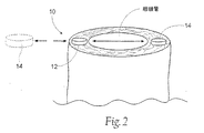
図2は、磁力システム10を図解的方法で示す。使用において、この磁力システム10
10は、睡眠中に、標的された咽頭構造における組織の崩壊、および咽頭管内の個々の解剖学的構成要素における組織の崩壊に抵抗する。
(I. Magnetic system)
FIG. 2 shows the
10, during sleep, the collapse of tissue in targeted pharyngeal structures and to resist collapse of tissue in the individual anatomical components of the throat head inner tube.
最も基本的形態では、この磁力システム10は、少なくとも一つの強磁性材料12、ならびに少なくとも一つの磁力供給源14を備える。この強磁性材料12は、咽頭管内の標的された組織領域に移植される。この磁力供給源14は、図2で矢印によって示されるように、この移植された強磁性材料12と相互作用する。この磁力は、この標的された組織領域内で磁場を発生して、所望の生理学的反応を実現する。この反応は、睡眠中に、標的された咽頭構造における組織の崩壊、および咽頭管内の個々の解剖学的構成要素における組織の崩壊に抵抗するための反応である。
In its most basic form, the
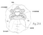
標的された咽頭構造およびこの領域内の個々の解剖学的構成要素としては、咽頭壁;舌根;谷;舌骨およびその付着部;口蓋垂、関連する柱組織を有する口蓋扁桃;および喉頭蓋が挙げられる。これらの解剖学的領域は、図1Aおよび図1Bに示される。特定の標的された咽頭構造および咽頭管内の個々の解剖学的構成要素における磁力システム10の実施形態の代表的な例は、以下により詳しく記載される。
Targeted pharyngeal structures and individual anatomical components within this area include the pharyngeal wall; tongue base; valley; hyoid bone and its attachment; uvula, palatine tonsil with associated columnar tissue; and epiglottis . These anatomical regions are shown in FIGS. 1A and 1B. Representative examples of embodiments of
(A.移植された強磁性材料)
強磁性材料12は、1より大きい透磁率(γ)を有する材料である。所定の強磁性材料は、「硬質」もしくは「軟質」であり得る。
(A. Implanted ferromagnetic material)
The
「硬質」強磁性材料は、一般的に永久磁石と呼ばれる。永久磁石は、一旦磁化された場合、外部の減磁する力に対する抵抗を示すことで特徴付けられる。永久磁石の残留磁気を除去するためには、強い外部磁場が必要とされる。言い方を変えれば、永久磁石は非常に強い内部保磁力を有し、これは、減磁へのその抵抗の指標となる。 “Hard” ferromagnetic materials are commonly referred to as permanent magnets. Permanent magnets are characterized by exhibiting resistance to external demagnetizing forces once magnetized. In order to remove the residual magnetism of the permanent magnet, a strong external magnetic field is required. In other words, permanent magnets have a very strong internal coercivity, which is an indicator of their resistance to demagnetization.
永久磁石は、外部磁場を発生し、隣の磁石に引力もしくは反発力のいずれかを及ぼし得る。永久磁石は、反対の極性の極を有する。これらの極は、磁気引力が得られる配置である。地球の地理学的な極に関連して、この磁石が自由に回転する場合、一つの極は地理学的な北極点を指し、したがってこれはN極と呼ばれ、反対側の極は、同様に、磁石のS極と呼ばれる。地球の地理学的な北極点は、その磁気的南極であり、永久磁石のN局を引きつける。物理学的法則に従って、極性の同じ極(N−NもしくはS−S)は、磁力によって互いに反発する。一方で、極性の異なる局は、(N−SもしくはS−N)は、磁力によって互いに引き合う。磁気の引力もしくは斥力の力は、磁石の強さおよび極間の距離に依存する。したがって、永久磁石は同じ極が互いに向かい合う場合は互いに反発し、反対の極が互いに向かい合う場合は互いに引き合う
公知の永久磁石材料の例としては、ネオジム−鉄−ホウ素合金(NdFeB)、アルミニウム−ニッケル−コバルト合金(AlNiCo)、およびサマリウムコバルト(SmCo)が挙げられる。
Permanent magnets generate an external magnetic field and can exert either attractive or repulsive forces on adjacent magnets. Permanent magnets have poles of opposite polarity. These poles are arranged so that magnetic attraction is obtained. When this magnet rotates freely in relation to the Earth's geographic pole, one pole refers to the geographic North Pole, so it is called the N pole and the opposite pole is the same It is called the south pole of the magnet. The geographical north pole of the earth is its magnetic south pole, which attracts N stations of permanent magnets. According to the laws of physics, poles of the same polarity (NN or SS) repel each other by magnetic force. On the other hand, stations with different polarities (N-S or S-N) attract each other by magnetic force. The magnetic attractive or repulsive force depends on the strength of the magnet and the distance between the poles. Therefore, the permanent magnets repel each other when the same poles face each other, and attract each other when the opposite poles face each other. Examples of known permanent magnet materials include neodymium-iron-boron alloys (NdFeB), aluminum-nickel- Examples include cobalt alloy (AlNiCo) and samarium cobalt (SmCo).
電磁石(ワイヤーのコイルを通じた電流の流れ)は、永久磁石の代わりにされ得る。 An electromagnet (current flow through a coil of wire) can be substituted for a permanent magnet.
「軟質」強磁性材料は、一旦磁化された後、非常に容易に減磁され得る。言い換えると、軟質強磁性材料は、磁化力が除去された後は、ほとんど残留磁気を保持しない。軟質強磁性材料は、非常に高い透磁率および飽和磁化を有するが、非常に低い内部保磁力を有する。軟質強磁性材料は、永久磁石もしくは電磁石によって引きつけられ得る。 “Soft” ferromagnetic materials can be very easily demagnetized once magnetized. In other words, the soft ferromagnetic material retains little residual magnetism after the magnetizing force is removed. Soft ferromagnetic materials have very high permeability and saturation magnetization, but have very low internal coercivity. The soft ferromagnetic material can be attracted by a permanent magnet or an electromagnet.
公知の軟質強磁性材料の例としては、鉄(Fe);ニッケル(Ni);パーメンジュール;ミューメタル;低炭素鋼;鉄−コバルト合金(Fe−Co);シリコン鋼;およびアモルファス合金が挙げられる。 Examples of known soft ferromagnetic materials include iron (Fe); nickel (Ni); permendur; mu metal; low carbon steel; iron-cobalt alloy (Fe-Co); silicon steel; It is done.
(B.磁力供給源)
磁力供給源14は、永久磁石を備える。電磁石(ワイヤーのコイルを通じた電流の流れ)は、永久磁石の代わりにされ得、磁力供給源として働き得る。
(B. Magnetic source)
磁力供給源14は、強磁性材料12と同様に、咽頭管内の標的された組織領域に移植され得る。移植された供給源14の説明的な例は、以下に記載される。あるいは、図2に点線(phantom line)で示されるように、磁力供給源14は、移植され得るか、または咽頭構造領域の外部(例えば、口腔内、頸部、頭部、もしくは下顎骨)に保持され得る。外部供給源14の説明的な例もまた、以下に記載される。
磁力によって作られる磁場は、多様に構成され得る。例えば、磁場は、移植された強磁性材料12を引きつけるように構成され得る。反対に、この磁場は、移植された強磁性材料12に反発するように構成され得る。磁場の性質は、移植された強磁性材料の型、および適用される磁力の型に依存する。これらは、次いで、システム10の解剖学的な向きが与えられると、所望の生理学的反応の型によって、決定付けられる。磁力システム10のこれらの局面は、以下でより詳細に議論および説明される。
The magnetic field generated by the magnetic force can be variously configured. For example, the magnetic field can be configured to attract the implanted
(II.磁力システムによって使用され得る説明的な強磁性材料の設計)
(A.放射状の磁気を有する永久磁石)
前に規定されたように、移植された強磁性材料12および/もしくは磁力供給源14は、永久磁石を備え得る。この永久磁石は、種々の方法およびで構成され得、かつ種々の形状(例えば、円筒、正方形、長方形、もしくは他の多角形)を取り得る。
II. Descriptive ferromagnetic material design that can be used by magnetic systems
(A. Permanent magnet with radial magnetism)
As defined before,
放射状の磁気を有する永久磁石が望ましい。なぜなら、それらは、この磁石の本体の中心から放射状に広がる方向へ磁束を向けるからである。この放射状の磁束方向のため、この永久磁石は、その外部表面全体の周りに同じ極(NもしくはS)を提示する。 A permanent magnet having a radial magnetism is desirable . This is because they direct the magnetic flux in a radial direction from the center of the magnet body. Because of this radial magnetic flux direction, the permanent magnet presents the same pole (N or S) around its entire outer surface.
例えば、図3Aは、図2に示されるシステム10において、移植された強磁性材料12および/もしくは磁力供給源14として使用され得る、放射状の磁気を有する円筒永久磁石16を示す。円筒永久磁石16は、外径18および内径20を有する。その放射状の磁気に起因して、一つの磁極P1は、外径18上にあり、そして一つの磁極は、内径20上にある。図3Bは、磁化されて、N極が外径18上にあり、そしてS極が内径20上にある円筒永久磁石16の断面である。図3Cは、磁化されて、S極が外径18上にあり、そしてN極が内径20上にある円筒永久磁石の断面である。図3Bおよび図3Cにおいて、矢印は、磁気モーメントもしくは磁束の代表的な方向を示す。この磁気モーメントもしくは磁束の方向はまた、磁化方向(magnetization direction)もしくは磁場配向方向(magnetic orientation direction)とも呼ばれる。図3Bおよび図3Cにおいて、この方向は、磁石本体の中心からの放射状の軌道上にあると見られ得、したがって、説明的な用語「放射状の磁気」であり得る。
For example, FIG. 3A shows a cylindrical
図4Aは、放射状の磁性を有する円筒形永久磁石アセンブリ22を示し、これは、移植された強磁性材料12および/または図2に示すシステム10における磁力源14として使用され得る。図4Aにおいて、放射状配向は、放射状磁化弧セグメント24のアセンブリによって達成される。弧セグメント24のアセンブリ22は、外径26および内径28を集合的に形成する。図4Aにおいて、8個の弧セグメント24は、アセンブリ22を形成する。いくつかの弧セグメント24またはそれより多くの弧セグメント24が、使用され得ることが、理解されるべきである。しかし、原則として、所定のアセンブリ22の弧セグメント24の数が多いほど、アセンブリ22は所望の放射状配向をよりよく達成する。弧セグメント24の数の制限は、もちろん、アセンブリ22の大きさである。図4Bは、北極がアセンブリ22の外径26上に、そして南極がアセンブリ22の内径28上に存在するように磁化された、8個の弧セグメント24を有する円筒形永久磁石アセンブリ22の断面図である。図4Cは、南極がアセンブリ22の外径26上に、そして北極がアセンブリ22の内径28上に存在するように磁化された、8個の弧セグメント24を有する円筒形永久磁石アセンブリ22の断面図である。図4Bおよび図4Cにおいて、矢印は、それぞれの磁気モーメントまたはフラックスの方向を示し、この配向は、アセンブリの中心からの放射状経路に存在し得ると考えられる。
FIG. 4A shows a cylindrical
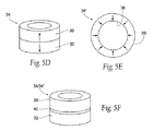
放射状様の磁性を有する永久磁石は、他の方法で作製され得る。例えば、図5Aは、各磁石の各本体に対応する各軸に沿って磁化された2つの永久環状磁石30および32を示す。この配置において、1つの極P1は、磁石環体30/32の1つの軸末端に存在し、そして他極P2は、磁石環体30/32の反対の軸末端に存在する。2つの磁石環体30および32は、それぞれ軸磁性を有し、類似の極が互いに向かい合うように集合し、アセンブリ34を作製する。
Permanent magnets with radial-like magnetism can be made in other ways. For example, FIG. 5A shows two permanent
図5Bは、2つの磁石環体30および32のアセンブリ34を示し、これらは、同じ北極が互いに向かい合うように集合する。図5Cは、図5Bで示したアセンブリ34の断面図である。図5Cが示すように、有限要素分析に基づき、アセンブリ34は、外径36上の北極および内径38上の南極を有する、放射状様の配向を有する。
Figure 5B illustrates the two
図5Dは、同じ南極が互いに面するように集合した2つの磁石環体30および34のアセンブリ34’を示す。図5Eは、図5Dで示したアセンブリ34’の断面図である。図5Eが示すように、有限要素分析に基づき、アセンブリ34’は、外径36上の南極および内径38上の北極を有する、放射状様の配向を有する。図5Cおよび図5Eにおいて、矢印は、磁気モーメントまたはフラックスのそれぞれの方向を示し、この配向は、アセンブリ中央からの放射状経路に存在し得ると考えられる。
Figure 5D shows the assembly 34 'of two
図5Bまたは図5Dいずれかのアセンブリ34または34’において、スペーサー40が、磁石環体30と32との間に導入され得る。図5Fは、磁石環体30と32との間のスペーサー40の存在を示す。スペーサー40は、この型の磁石と隣接する磁石との間の反発力を改善する。スペーサー40としては、任意の軟質強磁性材料(例えば、鉄、低炭素鋼、Fe−Co合金、シリコン鋼、パーメンジュール、またはアモルファス合金)が挙げられ得る。スペーサー40としてはまた、非磁気材料またはポリマーが挙げられ得るが、反発力の増大を最大化するために、軟質磁気材料の使用が、好ましい。
In either the
別の例として、図6Aは、各磁石のそれぞれの本体の軸に沿って磁化された、2つの永久円盤磁石42および44を示す。この配置において、1つの極P1は、磁石円盤42/44の1つの軸末端に存在し、そして他極P2は、磁石円盤42/44の反対の軸末端に存在する。2つの磁石円盤42および44は、それぞれ軸磁性を有し、同じ極が互いに向かい合うように集合し、アセンブリ46を作製する。
As another example, FIG. 6A, is magnetized along the axis of each of the body of each magnet shows two
図6Bは、2つの磁石環体42および44のアセンブリ46を示し、これらは、同じ北極が互いに向かい合うように集合する。図6Cは、図6Bで示したアセンブリ46の断面図におけるフラックス方向の有限要素分析である。図6Cで示すように、アセンブリ46は、アセンブリ46の外径48上に北極を有する、放射状様の配向を有する。
Figure 6B illustrates the two
逆に、図6Dは、2つの磁石環体42および44のアセンブリ46’を示し、これらは、同じ南極が互いに向かい合うように集合する。図6Cにおいて示されるような種類の有限要素分析は、アセンブリ46’が、外径48上に南極を有する、放射状様の配向を有することを実証する。
Conversely, FIG. 6D shows two assemblies 46 'of the
図6Bまたは図6Dいずれかのアセンブリ46または46’において、図6Eに示すように、スペーサー50が、磁石円盤体42と44との間に導入され得る。上述のように、スペーサー50は、この型の磁石と隣接する磁石との間の反発力を改善する。スペーサー50としては、任意の軟質強磁性材料または非磁気材料が挙げられ得るが、反発力の増大を最大化するために、軟質磁気材料の使用が、好ましい。
In
(B.軟質強磁性材料のコイル)
上述のように、移植された強磁性材料12は、軟質強磁性材料を含み得る。
(B. Coil of soft ferromagnetic material)
As described above, the implanted
軟質強磁性材料12は、種々の方法で形成され得る。
Soft strong
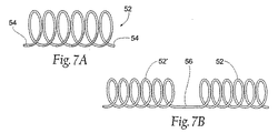
例えば、図7Aは、コイル52として形成された軟質強磁性材料を示す。コイル52は、サイズ処理され、そして咽頭収縮筋内の標的組織領域内の移植に適するように形成される。
For example, FIG. 7A shows a soft ferromagnetic material formed as a
コイル形態は、磁石に可撓性を与える。この可撓性は、移植片を、移植される組織の解剖学および組織の動きに容易に適合させることを可能にする。この可撓性はまた、移植される組織を硬化させることなく、コイルの移植を可能にする。咽頭収縮筋内の標的組織領域におけるコイル52は、望ましくは非外傷性末端54で形成される。
Coiled state gives flexibility to the magnet. This flexibility, the implant makes it possible to easily adapt to the anatomy and tissue motion of the tissue to be transplanted. This flexibility also allows for implantation of the coil without hardening the tissue being implanted. The
コイル52は、長さを短くするためにセグメント化され得る。より短い長さの52’は、図7Bで示すように、ポリマー接続材料56によって互いに組み合わされ得る。別々の任意の種類の磁石(硬質もしくは軟質、または電磁)が、この様式で組合され得ることが、理解されるべきである。
The
(C.システムと身体の組織/体液との間の相互作用を防ぐための保護材料の使用)
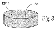
図8が示すように、強磁性材料12および/またはあらゆる形態または構造の磁力源14が、望ましくは、洗濯された保護材料58により、コートされるか、メッキされるか、包まれるか、または沈着される(特に、移植が意図される場合)。保護材料58は、耐食表面および生体適合性表面を提供するために選択され、強磁性材料12および/または磁力原14と身体の組織/体液との間の相互作用を防ぐ。保護材料58はまた、望ましくは、耐久性の組織界面を形成するために選択され得、システム構成要素の長い寿命を提供し、それにより、構造的疲労および/または故障に対する耐性を提供する。これらの所望の物理的および生理学的利点を提供するために選択された、保護材料58およびそのシステム構成要素への適用はまた、望ましくは、システム構成要素自身に不撓性を与えることを避けるように選択される。
(C. Use of protective material to prevent interaction between system and body tissue / fluid)
As FIG. 8 shows, the
保護材料58は、所望の生体適合性、耐食性および耐久性を提供することが公知の種々の型の材料から選択され得る。例えば、保護材料58としては、強磁性材料12および/または磁力源14上にメッキされたか、沈着されたか、またはそれ以外でコートされたチタン材料が挙げられ得る。別の例としては、保護材料58として、パリレンコーティングが挙げられ得る。他の例としては、保護材料58として、非毒性エポキシ、医療等級ポリウレタンまたはU.V.硬化性医療用アクリルコポリマーが挙げられ得る。
The
保護材料58はまた、抗凝結薬および/または抗生物質を組み込み得る(特に、システム10構成要素が、移植を意図される場合)。
The
(III.磁力システムに有用な例示的強磁性移植片アセンブリ)
(A.別種の磁石)
移植された強磁性材料および/または磁力供給源は、それぞれ、1種または別種の、所定の所望の配向を有する磁性の供給源を含み得る。例えば、強磁性材料の本体を含む1つの永久磁石は、所定の配向を有する磁性の1つの供給源を備え得る。
III. Exemplary Ferromagnetic Graft Assembly Useful for Magnetic Systems
(A. Another kind of magnet)
Transplanted ferromagnetic material and / or magnetic force source, respectively, of one or another species, it may include a source of magnetism having a given desired orientation. For example, one permanent magnet including the body of ferromagnetic material may comprise one source of magnetism having a given orientation.
別の例としては、結合した永久磁石が使用され得る。結合した磁石は、可撓性であるかまたは剛性であり、そして、可撓性または剛性の基材(例えば、ゴム、ニトリル、ポリエチレン、エポキシ、ポリビニルクロリド、またはナイロン)に結合した粉末NdFeB、フェライトまたはSmCo永久磁石材料で構成され得る。結合磁石の形成は、押し出し、圧縮成形、射出成形、カレンダ加工、または印刷によって達成され得る。結合磁石は、独特な可撓性設計、耐久高耐性形状(さもなければ達成は困難である)を可能にする。結合磁石設計は、種々の様式(例えば、多面様式(multiple faces)、放射同極様式(radial homopolar)、軸様式(axial)、および直径様式(diametrical))で磁化され得、そして等方性であっても異方性であってもよい。 As another example, a combined permanent magnet can be used. The bonded magnet is flexible or rigid and powder NdFeB, ferrite bonded to a flexible or rigid substrate (eg rubber, nitrile, polyethylene, epoxy, polyvinyl chloride, or nylon) Alternatively, it can be composed of SmCo permanent magnet material. The formation of the coupled magnet can be accomplished by extrusion, compression molding, injection molding, calendering, or printing. The coupled magnet allows for a unique flexible design, durable and resistant shape (otherwise difficult to achieve). The coupled magnet design can be magnetized in a variety of ways (eg, multiple faces, radial homopolar, axial, and diametric) and isotropic. Or may be anisotropic.
あるいは、移植された強磁性材料12および/または磁力供給源は、磁性(それぞれ、共通の所望の配向を共有する)の個々の供給源のアレイを含み得る。このアレイは、直接に接することなく、近接した空間を空けた磁性の個々の供給源を含み得る。
Alternatively, the implanted
個々のまたは別個の磁石の配置は、患者の環境および生理によって与えられ得、処置の具体的な領域の選択におけるより大きな融通性を、医師に提供する。例えば、所定の患者は、特定の領域においてより多くのまたはより厚い組織を有し得、体積の増加は、気道閉塞を引き起こし得る。医師は、その地点にさらなる反発エネルギーを配置することを選択し得る。さらに、小さい個々の磁石または鉄の小さな形状物を配置することは、長い片を配置するよりも、解剖学においてより容易で、かつ侵襲性が少ないことが見出され得る。 The placement of individual or separate magnets can be given by the patient's environment and physiology, providing the physician with greater flexibility in selecting specific areas of treatment. For example, a given patient can have more or thicker tissue in a particular area, and an increase in volume can cause airway obstruction. The physician may choose to place additional rebound energy at that point. Furthermore, it can be found that placing small individual magnets or small shapes of iron is easier and less invasive in anatomy than placing long pieces.
任意の2つの対極の解剖学的特徴に、等しくない数の磁石を有することが、所望され得る。例えば、ある解剖学的構造の1方にある1つの磁石は、その解剖学的構造の他方にある2つの磁石と面し得る。1つの磁石を、3または4の対峙する磁石に対抗させることが、所望され得る。対抗する解剖学的特徴における等しくない数の磁石の使用は、移植片の整列において、より多くの改変を可能にし得る。 It may be desirable to have an unequal number of magnets in any two counter anatomical features. For example, one magnet on one side of an anatomical structure may face two magnets on the other side of the anatomical structure. It may be desirable to counter one magnet against three or four opposing magnets. The use of unequal numbers of magnets in the opposing anatomical features may allow for more modifications in graft alignment.
(B.注射された軟質強磁性合金)
軟質強磁性物質は、注射によって組織中に移植され得る。例えば、注入可能な媒体に懸濁された軟質強磁性物質からなる磁性流体力学的(MR)液体は、所望の生理学的な反応を達成するために、組織中に配置され得る。MR流動体は、磁場への曝露および曝露される磁場の強さに基づいた異なった粘性レベルでの定義による。
(B. Injected soft ferromagnetic alloy)
Soft ferromagnetic material can be implanted into tissue by injection. For example, a magnetohydrodynamic (MR) liquid consisting of a soft ferromagnetic material suspended in an injectable medium can be placed in tissue to achieve a desired physiological response. MR fluids are by definition at different viscosity levels based on exposure to the magnetic field and the strength of the exposed magnetic field.
MR流動体は、粉末、小さなビーズ、または合金もしくはセラミック(例えば、酸化鉄またはカルボニル鉄)の削りくずを、合金の均一な分散液を作り出すための生体適合性の媒体と混合することによって作り出され得る。生体適合性媒体としては、ElastinTM媒体が挙げられ、または生体適合性である油もしくは低粘性の液体を含有し得るか、または、咽頭の壁の形成、位置決め、もしくはその組織の調子の改善を促進する生体適合性のコンパートメント内にパッケージングされる。MR流動体が内部に注入される媒体は、ポリ酢酸ビニル(PVA)であり得るか、または、生体適合性を提供するように、適切に密閉される発泡体であり得る。 MR fluids are created by mixing powder, small beads, or alloy or ceramic (eg, iron oxide or carbonyl iron) shavings with a biocompatible medium to create a uniform dispersion of the alloy. obtain. Biocompatible media include Elastin ™ media, or may contain biocompatible oils or low viscosity liquids, or improve pharyngeal wall formation, positioning, or tissue tone. Packaged in a biocompatible compartment that facilitates. Medium MR fluid is injected into the interior, or can be a polyvinyl acetate (PVA), or, to provide a biocompatible, it may be a foam that will be properly sealed.
あるいは、粉末、小さなビーズ、または軟質強磁性物質合金は、2液型のポリメタクリル酸メチル(PMMA)結合剤の乾燥成分と混合され得る。システム10に使用するための注入可能アクリルを作成するために、乾燥モノマーおよび軟質強磁性物質合金の組合せを重合するために、液体成分が添加され得る。一旦懸濁液がインサイチュでセットされると、それは、意図された、所望の生理的反応を達成するための解剖学的形態および位置を有する。さらに、磁性PMMAは、移植されたコンパートメントに注入され、成形および生体適合性を促進する。
Alternatively, powders, small beads, or soft ferromagnetic material alloys can be mixed with the dry components of a two-part polymethyl methacrylate (PMMA) binder. To make an injectable acrylic for use in
(C.可撓性磁性アレイ)
磁石の可撓性のある、または従順なアレイはまた、支持キャリア上のユニットとして保有される、個々の磁性の源を備え得るか、または、直接一緒に結合し得る(例えば、図7の磁石は、糸またはポリマー物質によって結合している)。
(C. Flexible magnetic array)
A flexible or compliant array of magnets can also comprise individual magnetic sources, held as units on a support carrier, or can be directly coupled together (eg, the magnet of FIG. 7). Are bound by thread or polymer material).
図9Aおよび図9Bは、強磁性物質62の可撓性アレイ60を示し、強磁性物質62は、「硬質」および/または「軟質」磁石を備え得る。硬質磁石は、種々の様式(例えば、多極表面様式、放射性等極の様式、軸様式または正反対の様式)における厚みをとおして磁化され得る。図9Aおよび図9Bにおいて、強磁性物質62は、永久磁石を備える。図9Aおよび図9Bにおいて、N極は、矢印によって示される方向に向く(すなわち、N極は、図9Aの上端にあり、そして、S極は、図9Bの上端にある)。永久磁石と同等のもの(同じ磁気配向を有する)が、可撓性ポリマーマトリックス64上に取り付けられる。さらに、アレイ60は、二つ一組で、または、他との組合せで使用され、標的となる咽頭構造および咽頭管内の個々の解剖学的な構成要素において、反発する力または引き付ける力のどちらかを提供し得る。図9Cは、N極が互いに面し、二つのアレイ60(1)と60(2)との間に存在する力を反発するように並んだ二つのアレイ60(1)および60(2)を示す。図2に示されるシステム10との関連で、第一マトリックス60(1)は、例えば、システム10の強磁性物質12を備えるように、標的組織領域に移植され得、第二マトリックス60(2)は、システム10の磁力の源14を備えるように、例えば、咽頭管内での移植によるか、または咽頭管の外側の移植もしくは外側の配置によって配置され得る。後に、さらに詳細に示されるように、磁性アレイ60(1)および60(2)が、標的となる咽頭構造および咽頭管内の個々の解剖学的な構成要素に関して所望の関係で配向される場合、崩壊から組織を守るために、アレイ60(1)とアレイ60(2)との間に存在する反発力が使用され得る。
9A and 9B show a
互いに面するS極と一緒に並んだ二つのアレイ60(1)および60(2)は、咽頭管に関して隣接して面する関係に適切に配置された場合、反発力の存在につながり、そして、同一の所望の生理学的反応につながる。 The two arrays 60 (1) and 60 (2) aligned with the S poles facing each other, when it is properly positioned adjacent to facing relationship with respect to throat head tube, leading to the presence of the repulsive force, and , Leading to the same desired physiological response.
図9Dは、S極の向きの第二アレイ60(2)に関して隣接して面するように配置されたN極の向きの第一アレイ60(1)を示す。2つのアレイ60(1)と60(2)との間に、引き付ける力が存在する。図2に示されるシステム10との関連で、第一マトリックス60(1)が、システム10の強磁性物質12を備えるように、例えば、標的組織領域に移植され得、そして、第二アレイ60(2)が、システム10の磁力の源14を備えるように、例えば、咽頭管内に移植されるか、咽頭管の外側に移植されるか、その外側に配置されるかすることによって、配置され得る。後に、より詳細に示されるように、アレイ60(1)および60(2)が、標的となる咽頭構造および咽頭管内の個々の解剖学的な構成要素に関して所望の関係で配向される場合、アレイ60(1)とアレイ60(2)との間に存在する引き付ける力が、組織を崩壊させないために使用され得る。
FIG. 9D shows a first array 60 (1) with an N-pole orientation arranged to face adjacent with respect to a second array 60 (2) with an S-pole orientation. There is an attractive force between the two arrays 60 (1) and 60 (2). In the context of the
図9Eに示されるように、機械加工されたか、レーザー切断されたか、化学的にエッチング処理されたか、またはEDM製造された軟質強磁性物質66(例えば、Hiperco 50A、HYMU−80、99.95% 鉄、または410ステンレス鋼)もまた、磁性アレイ60を形成するために、可撓性マトリックス上に、入れられるか、パッケージングされるかまたは他の方法で配置され得る。図2に示されるシステム10との関連で、アレイ60は、システム10の強磁性物質12を備えるように、例えば、標的組織領域中に移植され得る。この配置において、磁力の源14(例えば、永久磁石を備える第二アレイ、または単一の永久磁石、または電磁石を備え得る)は、移植した組織を崩壊させないように、引き付ける力を生み出すために、例えば、咽頭管内に移植するか、または咽頭管の外側に移植するか、もしくは配置することによって、配置され得る
マトリックス64は、好ましくは、生体適合性、耐久性、およびアレイに対して可撓性を与える物質から作製される。マトリックス64は、例えば、半剛性のポリマー物質(例えば、ポリカーボネート、シリコーンゴム、ポリウレタンなど)から作製される。可撓性は、患者に対して、改善された快適性、許容性および移植片に対する生物許容性を与える。可撓性はまた、マトリックス64が移植された解剖学的特徴に、マトリックス64が適合することを可能にする。可撓性の結果として、アレイ60は、咽頭管内の無差別の組織の硬化(望ましくない)によって、所望の生理学的反応(すなわち、組織崩壊耐性)を達成しないが、その代わりに、組織を押したり、また引いたりすることによって、制御された磁場の効果によって所望の生理学的反応を達成し、それは、咽頭管内の組織に剛性を与えない
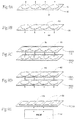
可撓性磁気アレイ60は、種々の物理学的形態で実現され得る。図10Aは、磁気ストリップアレイの一つの例示的な実施形態を示す。この実施形態において、個々の磁石62または軟質強磁性物質66は、キャリアストリップ物質68内にカプセル化される。磁石62または軟質強磁性物質66は、キャリアストリップ物質内に、間隔を開けて離れたパターンで配置される。キャリアストリップ物質68は、磁石62または軟質強磁性物質66を囲み、それによって、上に議論した保護物質58の機能的な利益を提供する。キャリアストリップ物質68内の磁石62または軟質強磁性物質66の間の間隔は、所望の不可欠な可撓性を提供する。
As shown in FIG. 9E, soft ferromagnetic material 66 (eg, Hiperco 50A, HYMU-80, 99.95%) that has been machined, laser cut, chemically etched, or EDM manufactured. Iron, or 410 stainless steel) can also be encased, packaged or otherwise disposed on the flexible matrix to form the
磁性ストリップアレイ60は、図10Aに示されるように、まっすぐな端面を有し得るか、または、組織内での固着を増強するために、図10Bに示されるように、不規則であるか、または曲がっていてもよい。キャリアストリップ物質68はまた、同じ目的で、穿孔されているか、または粗くなっていてもよい。組織の内殖における利点および好ましい点のさらなる詳細は、後に議論する。
The
可撓性磁性アレイ60はまた、既に記載した接着した磁石を使用して作製され得る。
The flexible
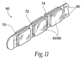
図11は、磁性ストリップアレイ60の別の実施形態を示す。このアレイ60は、磁石62または軟質強磁性物質66を、可撓性ポリマーストリップ70に加える。区域72は、磁石62または軟質強磁性物質66の間に、「一体の蝶番」を備えるストリップ内に形成される。一体の蝶番72は、強化した可撓性をアレイ60に与える。蝶番72は、アレイ60のどちらかの軸に沿って並べられ得る。形成された蝶番に代わる手段として、収縮区域が、図11の参照番号74に示されるように巻き込まれ得る。このような回旋74はまた、他のキャリアストリップ70より細いものであり得、可撓性の制御を提供するために使用され得る。
FIG. 11 shows another embodiment of the
図12は、磁性ストリップ60の別の実施形態を示す。この実施形態において、「膨張ストリップ(blister strip)」76は、減圧されるかまたは圧縮されて生体不活性なフィルムを形成し、ポケット78を備える薄壁ストリップを生成する。これらのポケット78は、大きさを合わされ、永久磁石62または軟質強磁性物質66を受け取るように設定される。結合表面80は、膨張ストリップ76の各半分に提供され、表面に反対側の膨張ストリップ76の接着剤シールまたはヒートシールを提供する。形成されたフィルム「膨張パッケージ」内に密閉される場合、磁石62または軟質強磁性物質66は、体液から防御され、そして、相互に所望の向きに保持される。細い頸部82は、蝶番を提供し、磁性ストリップが、先の実施形態に記載されるように収縮することを可能にする。反対側の膨張の半分を密閉した後、膨張ストリップパッケージ76は、後に記載されるように、適切な物質でコーティングされて、内殖および組織固着を促進する。
FIG. 12 shows another embodiment of the
単一の大きな磁石を使用する代わりに、可撓性マトリクス64上に配置された複数の磁石62の可撓性アレイまたは軟質強磁性材料66を使用することが、望ましいことが考えられる。これは、可撓性マトリクス64上にアレイ60で配置された磁石62または軟質強磁性材料66が患者に対して、適合性、許容性、および快適性を提供し、組織を堅くしないからである。個々の小さな磁石62または強磁性材料66のアレイ60を保持する可撓性マトリクス64の使用はまた、一連の小さな重複磁石モーメントまたは磁束場を生じる。これは、重複するフラックスの無い、大きなモノリシックな磁束場を生じ得る単一の大きな磁石の使用よりも、望ましいと考えられる。
Instead of using a single large magnet, it may be desirable to use a flexible array of
可撓性磁石アレイ60のサイズ、およびアレイ60の個々の磁石62または軟質強磁性材料66のサイズは、移植の容易さおよび生体適合性を考慮し、同時に、組織崩壊に抵抗するのに十分な磁力を提供し、移植の領域の解剖学およびシステム10の他の成分の配向を考慮して、選択される。1つの例として、12mmの幅、40mmの高さおよび3〜3.5mmの厚みのサイズが提供されるが、より大きな移植片またはより小さな移植片がまた、所望の生理学的応答を達成する。さらに、個々の磁石62または軟質強磁性材料66は、所望の生理学的応答が達成される限り、種々の幾何学的形状(矩形、円筒形、球形、卵形、など)を有し得る。
The size of the
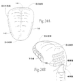
可撓性磁石アレイ60は、標的咽頭構造および咽頭管内の他の解剖学的構成要素内の移植に十分に適し、強磁性材料12または磁力の供給源14のいずれかあるいはその両方として役立つ。可撓性磁石アレイ60は、単独で、あるいは、他の強磁性材料と組み合わせて、または他の可撓性磁石アレイ60と直列で、または他の可撓性磁石アレイ60と平行して、または1つ以上の対の対向する磁石ストリップアレイ60において、そして水平または垂直のいずれかの解剖学的配向で、そして/あるいは咽頭管内で線形または曲線で移植され得る。例えば(図24を参照のこと)、永久磁石を有する可撓性磁石アレイ60は、舌の後部での移植に十分に適し、アレイは、望ましくは、舌の中心線の左側方および右側方の両方に配置される。この配置において、同じ磁気配向を有する永久磁石の他の可撓性アレイ60は、次いで、舌移植片の位置に対してちょうど反対の後部の側方咽頭壁の組織に移植され得る。舌移植片と側方咽頭壁の移植片との間の反発力は、組織が、特に、呼吸サイクルの相IVの間に、弛緩して近位にくるので、気道の崩壊に抵抗する。いくつかの他の配置が、可能であり、以下により詳細に記載される。
たったいま記載したシステム10の内容において、舌および側方咽頭壁上の反発する可撓性磁石アレイの間の距離は、睡眠の間の気道の閉鎖を妨げるために十分な反発力を対向するアレイの間に提供するが、嚥下を困難にするほど強力であるべきではない。これを達成するための力の量は、約4g/cm2よりも大きいと考えられる。
In the contents of the
記載される可撓性磁石アレイ60において、磁石62または軟質強磁性マトリクス64を有するポリマーマトリクス64は、細長ストリップとして構成されている。アレイ60が必ずしも細長ストリップの形態をとる必要があるわけではないことが認識されるべきである。アレイ60は、円形、または矩形、または正方形のレイアウトの形態をとり得る。実際には、標的移植部位の解剖学的要求および全体的な所望の生理学的応答に適合するために、任意の構成が採用され得る。さらに、マトリクス64は、1つより多くの列の磁石62または軟質強磁性材料64を有し得る。複数の列は、所定のマトリクス64に保持され得る。
In the described
(D.係留(tethered)磁石)
いくつかの場合において、個々の永久磁石62または軟質強磁性材料66の移植は、所望の生理学的応答を提供するために示され得る。個々の永久磁石または軟質強磁性材料が組織に移植される場合、組織内での移植片の移動に対して抵抗を提供する保持構造または固定(anchoring)構造84に磁石62または軟質強磁性材料66を係留することが望ましくあり得る。これは、移植領域が、比較的大きな軟質組織(例えば、舌)を提示する場合、特に関連する。磁石の係留は、磁力の供給源14に対して近位に磁石を配置することを可能にする。
(D. tethered magnet)
In some cases, implantation of individual
例として、図13Aは、保持構造または係留構造84にバンド86によって係留された永久磁石62または軟質強磁性材料66を示す。バンド86は、非再吸収可能縫合材料、他の織物生体適合性レースまたはファブリック、不織ポリマーストリップ(例えば、ナイロンまたはアセタール)、あるいは、生体適合性金属材料(例えば、ニッケルチタン合金(Nitinol(登録商標)))を含み得る。このような材料が非弾性である場合、バンド86はまた、弾性材料から作製され得る。このような弾性は、コンプライアンスおよび患者に対する増加した快適性を提供する。例えば、嚥下の場合、舌は、前方方向に移動し、そして弾性は、睡眠からの覚醒を妨げ得、さらに、磁石62または軟質強磁性材料66の移動を避け得る。
As an example, FIG. 13A shows a
保持構造84は、バンド86よりも幅広く、それによって、移植された磁石62または軟質強磁性材料66に、移植組織領域(図13Aにおいて幻影線で示される)を通してまたは移植組織領域からの引っ張りに対する抵抗を提供する。
The
保持構造84の材料は、劣化に抵抗し、一方で、不快または話すこともしくは嚥下に影響することを妨げるために十分な可撓性を示す、任意の生体適合性可撓性金属またはポリマー化合物であり得る。
The material of the
図13Aに示されるように、保持構造84は、穿孔88を備え得る。穿孔88は、保持構造84に対してより大きな可撓性を与える。穿孔88はまた、組織内殖を収容し、さらに、移植片の配置を確保し、そして移動を妨げる。
As shown in FIG. 13A, the
図13Bに示されるように、複数の保持構造84は、より広い領域に力を分布させるために、磁石62または軟質強磁性材料66に取り付けられ得る。図22Cはまた、同じ目的で、複数の保持構造を有する(舌における)移植片の使用を示す。
As shown in FIG. 13B, a plurality of retaining
(D.磁性移植片の固定)
(1.機械的固定材料の使用)
移植された強磁性材料12および磁力の供給源14の位置(移植された場合)は、外科の分野において公知の従来の機械的固定材料および技術(例えば、非再吸収可能縫合糸、ねじ、またはステープル)を使用して、咽頭管内の標的組織領域内での移動に対して固定され得る。例えば、図10、11、および12に示される磁石62または軟質強磁性材料66のアレイは、固定材料(すなわち、縫合糸、ねじ、またはステープル)を収容するために、予め形成された開口部90を備え得る。図13に示される実施形態において、保持構造は、同じ目的のための予め形成された開口部90を備え得る。
(D. Fixation of magnetic graft)
(1. Use of mechanical fixing materials)
The location of the implanted
所定の磁気移植片が固定される組織としては、咽頭壁の軟質組織、舌根;谷;口蓋垂;関連する柱組織を有する口蓋扁桃、および喉頭蓋が挙げられ得る。組織はまた、以下に記載されるように、骨(例えば、錐体または舌骨)およびその付属物を含み得る。 The tissue to which a given magnetic implant is fixed, soft tissue pharyngeal wall, the base of the tongue; Valley; uvula; palatine tonsils with associated pillar tissue, and may epiglottis can be mentioned. The tissue can also include bone (eg, cones or hyoid bone) and its appendages, as described below.
(2.移植スリーブの使用)
図14Aに示されるように、単一の磁石62または軟質強磁性材料66、あるいは磁石62または軟質強磁性材料66のアレイ60は、移植されたスリーブ92内への移植の間に挿入され得る。スリーブ92は、標的組織領域の、例えば、切開内に配置される。外科医は、縫合、ステープリング、またはねじ止めによってスリーブ92を適所に固定し得る。スリーブ92の挿入および固定に続いて、磁石62/66または磁石アレイ60は、図14Aにおいて矢印によって示されるように、スリーブ92内に配置される。スリーブ92の頂部および切開の開口部は、縫合または他の受容された閉鎖手段(例えば、ステープリングなど)によって閉鎖される。
(2. Use of transplant sleeve)
As shown in FIG. 14A, a
磁石移植片を受容するためのスリーブ92の使用によって、外科医は、標的組織領域内に移植される磁石成分のタイプ、強度または数を容易に変更または力価決定し得る。このような変更を行うために、切開は、スリーブ92の対向する端部においてなされ、そして磁石または磁石アレイは、スリーブからスライドし、変化が望ましいとみなされる場合、異なる磁石の強度またはタイプによって置換される。これは、移植片周囲の組織を切断して、既存の移植されたアレイを除去することよりも、より簡単で、迅速で、そしてより病的でない手順である。
The use of the
スリーブ92の使用によってまた、スリーブ92に対する組織内殖が、強磁性材料66が設置される前に、行われ得る。
Through the use of the
スリーブ92は、すでに記載された保護材料58の特徴を有する材料から作製される。さらに、スリーブ材料はまた、望ましくは、手短に記載されるように、望ましくは、組織内殖を収容するかまたは促進する。
The
図14Bにおいて、スリーブ92は、組織内のスリーブ92の増加した安定性および固定を与える一体化固定デバイスを備え得る。この実施形態において、スリーブ92は、スリーブ92の移植後に周りの組織内に展開され得るウイングまたはバーブ94を備える。ウイング94の適切な時間での展開は、種々の方法で達成され得る。例えば、各ウイング94は、蝶番付き支持アーム96を備え得る。アクチュエータツールTがスリーブ92内に挿入される(図14Bにおいて幻影線で示される)場合、アクチュエータツールTは、連続して支持アーム96に接触する。ツールTによって接触する場合、各支持アーム96は、連続して、揺れ動き、蝶番点で旋回し、組織内にウイング94を展開する。ウイング94の先端は、組織のブラント貫通(blunt penetration)を引き起こすように構成され得るか、または減少した貫通力が望ましい場合、鋭くなり得る。一旦全てのウイング94が展開されると、アクチュエータツールTは、引き出され、そして磁石62/66または磁石アレイ60は、スリーブ92内に挿入される。あるいは、磁石62/66または磁石アレイ60の挿入が、ウイング94を展開するために使用され得、この場合、別のアクチュエータツールTは、必要とされない。
In FIG. 14B, the
ウイング94が直接的に、スリーブ92の使用とともに、磁石アレイ60上に組み込まれ得ることが理解されるべきである。
It should be understood that the
ウイング94は、組織内での回転および移動に対して、スリーブ92に対して増加した安定性および抵抗性を提供する。これは、増加した組織内殖の必要性を減少し得、そしてより簡単かつ安全な手順で任意の移植されたデバイスを除去し得る。スリーブ92を除去する理由が存在する場合、ウイング94は、移植部位からのスリーブ92の引き出しに応答して組織から引き出されるように構成される。
(3.磁石ステープルアセンブリ)
図15Aは、取り付けられたかもしくは一体化したステープルフランジ100を備える永久磁石62または軟質の強磁性体66を備える、磁石ステープルアセンブリ98を示す。一体化したステープルフランジ100は、咽頭管内で、組織の粘膜内にできるだけその組織表面の近くに磁石ステープルアセンブリ98を移植することを可能にする。このようにして、磁石ステープルアセンブリ98は、睡眠中に組織崩壊が生じ得る場合に、標的の移植領域において(特に、その最も弛緩した状態で)軟組織の伸展性に従う。
(3. Magnetic staple assembly)
FIG. 15A shows a
磁石ステープルアセンブリ98は、組織弁または切開の内部に留められて、咽頭管への磁気要素の直接的な露出を最小限にし得る。この配置において、ステープルフランジ100のみが、屈曲した状態で咽頭管の内部に露出され、組織弁または切開の内部から外側へ突出する。この状況において、切開は、生物接着剤または封止剤を用いて封着され得る。
あるいは、磁石ステープルアセンブリ98は、標的の咽頭構造物および咽頭管内の解剖学的構成要素に直接留められ、磁石ステープルアセンブリ98の大部分が露出したままにされ得る。この状況において、磁石ステープルアセンブリ98を、例えば、創傷治療薬を塗布するかまたは創傷治療薬で処理したヒドロゲルでコーティングすることによって、組織治癒が促進され得る。
Alternatively, the
単一の磁石ステープルアセンブリ98は、標的の組織領域に移植され得る。あるいは、磁石ステープルアセンブリ98は、所望の生理学的応答を達成するように、隣接する磁石を反発するかもしくは引き付けるために選択された水平配置および/または垂直配置(図15Bを参照のこと)で、咽頭管内の標的の咽頭構造物および解剖学的構成要素の複数の部位に移植され得る。
A single
ステープルフランジ100は、種々の方法で、永久磁石62または軟質の強磁性体66に取り付けられ得る。例えば、ステープルフランジ100を永久磁石62または軟質の強磁性体66に一体的に取り付けるために、電気成形、接着、または匹敵する手段が使用され得る。あるいは、図15Cに示されるように、ステープル成分102は、金属エッチングまたはレーザー切断によって、別個に形成され得る。この配置において、ステープル要素102は、永久磁石62または軟質の強磁性体66を受容し、機械的に挟み、そして保持し、これによって、複合磁石ステープルアセンブリ98を形成するためのタブ104を備える。
The
磁石ステープルアセンブリのステープル要素102は、ステンレススチールまたはニッケルチタンNitinolTM(NiTi)材料から作製され得る。電気成形される場合、材料は、その延性のために選択された任意の電着金属物質(例えば、金または白金)であり得る。
The
(4.咽頭管内の骨(椎体)への固定)
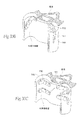
いくつかの場合において、骨への固定を伴う、咽頭管における1以上の永久磁石または軟質の強磁性体の移植が示され得る。図30A、30B、および30Cは、可撓性を有し、磁気的可撓性を有さないアーム150に取り付けられた磁石148を示し、このアーム150は、1以上の咽頭壁の外側に移植され、そしてさらに骨用ネジ152で椎体に固定されている。骨への固定は、移植された磁石の位置を安定化する。アーム150は、単列で水平に配向されても、(図30Cに示したように)咽頭管に沿って垂直に積み重なった関係に配向されても、(図30Bに示したように)咽頭の側面壁内で角経路(angular path)に配向されてもよい。配向に依存して、アーム150は、組織の形態に適合するように成形され得る。
(4. fixed to the bone (vertebral body) in the throat head tube)
In some cases, with a fixation to the bone, implantation of one or more permanent magnets or soft ferromagnetic material in the throat head pipe can be shown. FIGS. 30A, 30B, and 30C show a
(5.咽頭管の外側の骨(舌骨)への固定)
骨への固定を伴う、咽頭管の外側での1以上の永久磁石または軟質の強磁性体の移植もまた、示され得る。例えば、舌骨は、軟骨および付着した筋肉を有し、そして舌骨の運動は、咽頭および咽頭管の周辺組織に影響を及ぼし得る。数人の患者において、舌骨の前方運動および下方運動を予防することは、咽頭管の開放を保つことを補助し得る。
(5. on the outside of the throat head tube bone (fixed to the hyoid bone))
With a fixation to the bone, implantation of one or more permanent magnets or soft ferromagnetic material outside the throat head tube may also be shown. For example, hyoid bone has cartilage and attached muscle, and movement of the hyoid bone can affect the surrounding tissue of the throat and throat head tube. In some patients, preventing the forward movement and downward movement of the hyoid bone can assist in keeping the opening of the throat head tube.
図31は、コードもしくはバンド156によって舌骨の主要部につながれた磁石154(これは、軟質の強磁性体または永久磁石を含み得る)を示す。コードもしくはバンドは、クリンプリング158によって舌骨の主要部に取り付けられる(531)。バンド156は、非再吸収性の縫合材料、他の生体適合性のレース織物もしくは線維織物、不織ポリマー片(例えば、ナイロンまたはアセタール)、あるいは生体適合性の金属物質(例えば、ニッケルチタン合金(Nitinol(登録商標)))を含み得る。
FIG. 31 shows a magnet 154 (which may include a soft ferromagnet or a permanent magnet) connected to the main part of the hyoid bone by a cord or
コードもしくはバンド156は、磁石154が、下顎骨結合に対して近位に配置されることを可能にする。コードもしくはバンド156はまた、舌骨に対して磁石154に作用する力を伝達する。
The cord or
使用時に、移植された磁石154は、例えば、口腔内に配置される磁力の供給源14と相互作用し得る(この目的のために適合された口腔器具は、以下でより詳細に記載される)。供給源14との相互作用は、例えば、(バンド156を介して)力を及ぼして、舌骨に向かって上向き/前方方向に、磁石154を引き付け得る。磁気引力は、舌骨における上向きの角力および前向きの角力を保ち、下向きおよび後方への下垂を予防し、これによって、咽頭管の開放を維持することを補助する。
In use, the implanted
(5.組織内殖表面)
任意のまさに記載した組織固定化方法(図16を参照のこと)に加えて、磁気移植片(図16において一般的にMIで表される)は、組織内殖表面106を備え得る。表面106は、磁気移植片MI上の周辺組織の内殖を促進する環境を提供する。内殖が生じる場合、移植された磁気移植片MIは、しっかりと固着され、組織からの移動または押出に抵抗する。組織内殖表面106は、このようにして組織接着および安定化を増強し、これによって、標的の移植部位における磁気移植片MIの位置をさらに安定化しかつ固定する。
(5. organization ingrowth surface)
In addition to any just described tissue immobilization method (see FIG. 16), the magnetic implant (generally expressed by MI 16) may comprise a
組織内殖表面106は、種々の方法で形成され得る。例えば、表面106は、天然では生物学的に不活性で、生体組織による内殖を支持することが公知の開放発泡構造または線維構造を備え得る。この特性を示す1つの物質は、発泡PTFE(ポリテトラフルオロエチレンまたはTeflon(登録商標)−DuPont)である。この物質は、放射線照射して、物質の構造を破壊し、本質的に線維状にすることによって調製され得る。生じる物質は、開放性かつ多孔性であり、流体が入り得かつ生体組織が付着し増殖し得る裂を提供する。顆粒表面または線維表面を提供するように処理またはコーティングされた場合、他のこのような不活性ポリマーおよび均一な金属(例えば、ニッケルチタン−Nitinol(登録商標))は、組織内殖のための基板を提供する。内殖マトリックスの代替形態は、開放線維性質または顆粒性質を達成するために照射されるべき物質の代わりに、開放発泡ポリマーフォーム(例えば、PVAフォーム)であり得る。
内殖表面106はまた、例えば、ポリジメチルシロキサン(PDMS)またはポリウレタン(PU)上に配置された、織られたかまたは編まれたDacron(登録商標)(PET)布;電気成形加工によって作製された金属表面構造;焼結金属表面(例えば、ステンレススチール、白金、イリジウム、またはそれらの合金);パリレンコーティング;あるいは拡散が限定された凝集シリコーンを備え得る。内殖表面106はまた、機械的構造(例えば、磁気移植片に関して適切な寸法のスパイク、ステープル、タイム(time)、コイル、または穿孔)を備える。金属移植片はまた、凝血を促進するための化合物および/または感染を予防するための抗生物質を含み、単独でかまたは内殖表面106と組み合わせて使用される。
磁気移植片が機械的に固着され、一方で、内殖が生じる得ることが望ましくあり得る。仮固着は、再吸収可能な縫合糸、ネジまたは再吸収可能な物質(ポリグリコール酸または他の類似の化合物)で作製された他の機械的ファスナーの使用によって達成され得る。組織接着剤はまた、組織接着、組織固定、および組織安定化を提供するために使用され得る。 It may be desirable that the magnetic implant be mechanically anchored while ingrowth can occur. Temporary anchoring can be achieved by the use of resorbable sutures, screws or other mechanical fasteners made of resorbable materials (polyglycolic acid or other similar compounds). Tissue adhesives can also be used to provide tissue adhesion, tissue fixation, and tissue stabilization.
(i)一時的なシャントデバイス
図17Aは、一時的なシャントデバイス108の使用を示し、この仮のシャントデバイス108は、組織内殖期間中に、内殖表面106を有する磁気移植片MIと組み合わせての使用のために寸法を合わされ、そして構成される(図17Bを参照のこと)。シャントデバイス108は、適切な磁力によって提供される磁場を分路する(shunt)するかまたは短絡(short)するために選択される物質で作製され、その結果、磁気移植片MIは、組織内殖が起こっている間の磁場の結果として、移動または運動しない。図示目的のために、図17Bにおいて、磁気移植片MIは、咽頭壁に沿って垂直に固定されて示される。
(I) Temporary Shunt Device FIG 17A shows the use of a
図17Aに示されるように、シャントデバイス108は、層を成して構築された1以上の軟質の強磁性体合金110/112を備える。層110/112は、例えば、HYMU−80材料、2V Permendur材料;Hiperco 50A材料;Puron材料;ステンレススチール410または17−4材料;または1010炭素スチール材料;3N5(99.95%)鉄材料;あるいは高い透過性および/または高い飽和度を有する任意の他の適切な金属の合金を含み得る。これらの材料は、基板上にコーティングされ得る。
As shown in FIG. 17A, the
図17に示されるように、シャントデバイス108は、やわらかい磁性体合金の層110/112を備える。シャントデバイス108は、望ましくは、(すでに記載したように)生体適合性、耐腐食性、および耐久性のために保護材料58でコーティングされる。シャントデバイス108は、望ましくは、それ自体を、(図17Bに示されるように)磁気移植片MIを覆う標的組織部位の表面に対して、縫合するかまたはステープルでとめることによって一時的に付着させる。図17Aにおいて、アパーチャ114は、この目的のために提供される。あるいは、シャントデバイス108は、移植され、その後、除去され得る。あるいは、シャントデバイス108は、磁気移植片の表面に対して、除去可能に付着され得る。望ましくは、(磁気移植片MIとは異なり)シャントデバイス108は、組織の内殖を最小化するために、表面処理される。このことは、組織の内殖が磁気移植片上において十分な程度にまで進行した後の、シャントデバイス108の除去を容易にする。
As shown in FIG. 17, the
シャントデバイス108の材料および構築は、望ましくは、可撓性を与え、正常な解剖学的機能(例えば、嚥下)の妨害を回避する。図17Cに示されるように、可撓性は、例えば、ポリジメチルシロキサン(PDMS)またはポリウレタン(PU)のような材料116の合金構造セグメントと一体化することによって、得られ得る。他の適切なエラストマー(例えば、Hytrel(登録商標)材料)もまた、可撓性を与えるために、使用され得る。これらのセグメント材料116はまた、シャントデバイス108を、磁気移植片MIの全磁気断面に適合することを、可能にする。
The material and construction of the
(IV.磁力システムとともに使用可能な例示的な外部強磁性アセンブリ)
以前に述べたように、磁力の供給源14は、咽頭管中の標的組織中に移植された永久磁石(または電磁石)を備え得るか、あるいは、移植されたか、または咽頭管の外部に運ばれた永久磁石(または電磁石)を備え得る。咽頭管内の強磁性体材料と効果的に磁気相互作用をするための外部供給源を位置づけるための生存能力のある部位としては、口腔、頚部、顎、頭部、およびおとがい(頤)が挙げられる。システム10は、口の内部、頚部上、または頭部上に装着される種々の外部器具の選択物を含む。これらの選択物から、臨床医は、磁力供給源のための外部支持部位を作製するために選択し得る。これら器具の代表的な例を、ここに提示する。器具は、望ましくは、デバイスの移植片から適切な時間が経過した後に、装着されて、移植片の安定化、組織の内部成長、および治癒の発生を可能にする。
(IV. Exemplary External Ferromagnetic Assembly Usable with Magnetic System)
As mentioned previously, the
(A.経口器具)
口腔中に装着される器具は、標的となる咽頭構造および/または咽頭管内の解剖学的構成要素中に移植片された強磁性材料と相互作用するための、磁力の外部供給源を提供し得る。
(A. Oral device)
Instrument mounted in the oral cavity, provided to interact with the anatomic components ferromagnetic material which is graft during pharyngeal structures and / or throat head in tube to be targeted, the external source of magnetic force Can do.
(1.引力としての磁力の提供)
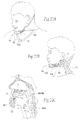
1つの例示的な配置を図18Aに示す。磁力供給源14(例えば、1つ以上の永久磁石62)を、経口器具118によって、保持する。経口器具118は、下の前歯上に装着されるように大きさをあわせ、そして構成される(図18Bを参照のこと)(望ましくは、睡眠時間中)。永久磁石は、任意の形状、大きさ、組成、および/または配向であり得る。すでに説明したように、永久磁石を、電磁石に置換し得る。
(1. Provision of magnetic force as attractive force)
One exemplary arrangement is shown in FIG. 18A. The magnetic source 14 (eg, one or more permanent magnets 62) is held by the
経口器具118は、下の前歯に装着されるように適合され、睡眠中に口腔の全部において、安定した様式において、供給源14の位置を保つ。この経口器具の一般的な構造は、他の目的の歯科医師にとって、周知であり、そして、歯科医師によって得られた型穴から、各患者のために作製される。経口器具118は、下顎が完全に自由に運動することを可能にする。
The
図18Bにおいて示された実施形態において、所望の生理学的応答(気道組織崩壊への耐性)が、舌の前方(前部)中に移植された強磁性体材料12と相互作用する磁場Fを形成する供給源磁石62によって、達成される。移植された強磁性材料12は、供給源14の磁石62の反対の磁気配向を有する永久磁石、またはやわらかい強磁性材料を備え得る。永久磁石またはやわらかい強磁性材料は、任意の形状、大きさ、組成および/または配向であり得る。移植された強磁性材料12は、図13Aおよび13Bにおいて示され、そしてすでに記載したように、係留された移植片のタイプであり得る。反対の磁石の配向の間の磁場Fは、引力を形成する。引力の結果として、舌が、前方に(口腔の前方に向けて)引き出され、舌の基底にある気道の閉塞に抵抗する。
In the embodiment shown in FIG. 18B, the desired physiological response (resistance to airway tissue collapse) forms a magnetic field F that interacts with the
図18Cに示されるように、2つの強磁性移植片12(1)および12(2)が、舌の反対の側面に提供され得る。この配置において、経口器具118は、強磁性移植片12(1)および12(2)と磁気的に整列された永久磁石62(1)および62(2)の対応する数を保持する。従って、引力は、舌の右前面側面および左前面側面に同時に適用される。
As shown in FIG. 18C, 2 two ferromagnetic implants 12 (1) and 12 (2) may be provided on opposite side of the tongue. In this arrangement, the
(2.反発する磁力を提供する)
別の例示的配置を、図19Aに示す。磁力供給源14(例えば、1つ以上の永久磁石62)を、睡眠時間中に下の歯に装着するように、大きさを決めて、構成された経口器具120によって、保持する(図19Bを参照のこと)。永久磁石は、任意の形状、大きさ、組成、および/または配向であり得る。既に説明したように、永久磁石62を、電磁石に置換し得る。
(2. Provide repulsive magnetic force)
Another exemplary arrangement is shown in FIG. 19A. A magnetic source 14 (eg, one or more permanent magnets 62) is sized and held by an
図19Aおよび19Bに示される経口器具120の構成は、一般に、歯ぎしりまたはいびきを防ぐために使用される歯科器具と類似する。この一般的なタイプの経口器具は、これらの目的の歯科医師にとって、周知であり、そして、歯科医師によって得られた型穴から、各患者のために作製される。経口器具120は、下顎が完全に自由に運動することを可能にする。
The configuration of the
図19Bにおいて、経口器具120は、下の歯に適合するように示される。この適合は、望ましくは、睡眠の前に達成される。経口器具120は、臼歯の後部の所望の位置において、供給源14の磁石62を保持する。磁石62は、経口器具120によって、下顎の上、または下顎の側面にそって外側に、または下顎の側面にそって内側に保持され得る。これら位置の任意の組み合わせを、使用し得る。
In FIG. 19B, the
図19Bにおいて示される実施形態において、所望の生理学的応答(気道組織崩壊に対する耐性)が、咽頭壁と相互作用する磁力Fを生成する供給源14によって、達成される。移植された強磁性材料12は、供給源14の磁石62の磁気配向と同一の磁気配向を有する永久磁石を備え得る。永久磁石は、任意の形状、大きさ、組成、および/または配向であり得る。磁気配向の間の磁場が、反発力を生じる。反発力は、咽頭管中の組織崩壊に対する耐性を提供し、気道の崩壊に抵抗する。
In the embodiment shown in FIG. 19B, the desired physiological response (resistance to airway tissue collapse) is achieved by the
(B.頚部器具)
頚部周囲に装着される器具もまた、標的となる咽頭構造および/または咽頭管内の解剖学的構成要素中に移植片された強磁性材料と相互作用するための、磁力の外部供給源を提供し得る。
(B. Neck device)
Instrument is mounted around the neck also for interacting with anatomic components ferromagnetic material which is graft during pharyngeal structures and / or throat head in tube to be targeted, the external source of magnetic force Can be provided.
図20Aは、完全な頚部カラー122の例示的な構成を示す。この頚部カラーは、頚部周辺に完全に装着されるように、大きさが決められ、そして構成される(図20Bを参照のこと)。カラー122は、例えば、快適さのための布で覆われたフォーム材料であり得、そして、(図20Aに示すように)伸縮性クロージャーストリップ(stretch closure strip)124を備え得る。あるいは、カラー122は、フックおよびループファスナー(例えば、Velcro(登録商標)材料)、または、単純に、バックルまたはフックおよび閉鎖のための視覚手段を備え得る。織物は、好ましくは、カラー122を覆い、装着者の快適さを増強する。覆う織物は、例えば、タオル地またはジャージタイプの織物であってもよく、洗浄のために着脱可能であり得る。さらに、カラー122は、望ましくは、フォーム内に包まれるか、またはフォームの外側表面を包む強化部材(示さず)を備える。強化部材は、カラーの形状の制御を提供し、そして、カラー122が広がって若干開いて、カラー122の装着および除去を可能にするのに十分なバネ特性を有する。
FIG. 20A shows an exemplary configuration of a complete
図20Aにおいて示される実施形態において、カラー122は、顎の骨の背後にとどまる曲率を有し、睡眠中にカラー122が回転するのを防ぐ。明確に規定される顎を有さない患者(例えば、肥満の人)について、付着性のパッチを取り込んで、カラー122の回転を妨げることが好ましくあり得る。
In the embodiment shown in FIG. 20A, the
図20Aに示されるように、カラー122は、1つ以上の永久磁石62を備える磁力供給源14を保持する。永久磁石は、任意の形状、大きさ、組成、および/または配向であり得る。
As shown in FIG. 20A, the
図20Aにおいて示される実施形態において、永久磁石62は、カラー内のポケット126に挿入され得る。ポケット126は、臨床医または医療技術者が患者の要求に対して適切なタイプと強さについて磁石62を選択することを、可能にする。ポケット126はまた、咽頭管中に移植された強磁性材料12と相互作用するために、供給源磁石62の配置を臨床医が選択することを可能にする。磁石は、単一の磁石であっても、複数の磁石であってもよい。電磁石を、永久磁石の代わりに使用し得る。
In the embodiment shown in FIG. 20A, the
図20Aにおいて示される実施形態において、ポケット126は、カラー122の左側、カラー122の右側、およびカラー122の前面において、永久磁石62のアレイの配置を提供する。臨床医は、所望の生理学的応答に従って、配置を選択する。
In the embodiment shown in FIG. 20A, the
図20Cにおいて示される実施形態において、臨床医は、カラー122の右側ポケットおよび左側ポケット126中に、永久磁石62のアレイを挿入する。この配置において、所望の生理学的応答(気道組織崩壊への耐性)が、咽頭壁の左側面および右側面(すなわち、脊柱の左側および右側上に伸長する気道壁の部分であり、通常は、気道壁の正中線にほぼ沿って伸長する部分)に移植された強磁性材料12と相互作用する磁場F1およびF2を生成する供給源磁石62によって、達成される。移植された強磁性材料12は、軟質の磁性体または永久磁石のいずれかであり得る。移植された永久磁石の場合、磁石は、供給源14の磁石62の磁気配向と反対方向の磁気配向を有する。永久磁石は、任意の形態、大きさ、組成、および/または配向であり得る。反対の磁気配向の間の磁場F1およびF2は、カラー122に保持される磁石62と移植された磁石12との間に、引力を生じる。引力F1およびF2は、咽頭管内における組織の崩壊に対する耐性を提供し、気道の閉塞に抵抗する。
In the embodiment shown in FIG. 20C, the clinician inserts an array of
図20Cにおいて示される実施形態において、臨床医はまた、カラー122の前側ポケット126中に、永久磁石62のアレイを挿入する。永久磁石は、任意の形態、大きさ、組成、および/または配向であり得る。
In the embodiment shown in FIG. 20C, the clinician also inserts an array of
この配向において、所望される生理学的応答(気道組織崩壊の耐性)が、舌の後方(基底)中に移植される強磁性材料12’と相互作用する磁場F3を生成するカラー122の前面上の供給源磁石62によって、達成される。カラー122の供給源磁石は、移植された強磁性材料12’(軟質の磁性材料または永久磁石のいずれかであり得る)に対して引力をおよぼす。永久磁石の場合、磁石は、カラー122の前面における供給源14の磁石62の磁力配向と反対の磁力配向を有する。永久磁石は、任意の形態、大きさ、組成、および/または配向であり得る。移植片12’は、例えば、図13Aおよび13Bにおいて示され、そして既に述べた、係留した移植タイプであり得る。
In this orientation, the desired physiological response (resistance to airway tissue collapse) is on the front surface of the
対向する磁性配向の間の磁力F3は、引力を作り出す。引力Fの結果として、その舌は、上側に、口腔の前面に向かって引っ張られて、その舌の基部において気道の閉塞に抵抗する。 Magnetic force F3 between the magnetic orientation opposed, creating a pull force. As a result of the pull force F, the tongue, the upper is pulled toward the front of the oral cavity, it resists obstruction of the airway at the base of the tongue.
図20Cに示される実施形態において、側方咽頭壁に、および舌の後ろに移植された強磁性物質12および12’は、全て同じ磁性配向を有する永久磁石であり、その永久磁石は、供給源カラー122によって有される磁石62の磁性配向とは反対である。そのカラー122における磁石62と咽頭管に移植された強磁性物質12および12’との間に誘引磁力F1、F2およびF3を作り出すのは、この反対の磁性配向である。その移植された強磁性物質12および12’の中でのその同じ磁性配向はまた、咽頭管における組織内で反発力を作り出す。その反発力自体は、その咽頭管の閉塞に抵抗する。この動的な相互作用は、(移植片に対するカラーを)咽頭管の中心から離してその移植された強磁性物質12および12’を引きつける(すなわち、保持する)磁力を提供し、これは、その移植片自体の間の(移植片から移植片の)反発力を補助する。増強された生理学的応答は、動的相互作用によって作り出される。
In the embodiment shown in FIG. 20C, the
カラー122の配置は、移植された強磁性物質12および12’の解剖学的配置および位置に依存して変動し得る。このことを考慮に入れると、所定のカラーは、首の周りを完全に一周する必要はない。
The arrangement of the
例えば、部分的襟カラー128は、図21Aに示される。そのカラー128は、首の側面および背面に装着される。この配置において(図21Bを参照のこと)、医師は、永久磁石62のアレイを、カラー128の左側面ポケットおよび右側面ポケット126、ならびにカラー128の背面のポケット126に挿入する。この配置において、所望の生理学的応答(気道組織の崩壊の抵抗)が、磁場F1、F2、およびF3を作り出す供給源磁石62(これは、咽頭壁の左側側面および右側側面に移植される強磁性物質12のアレイと相互作用する)によって達成される。その移植される強磁性物質12は、供給源磁石62の磁性配向と反対の磁性配向を有する。反対の磁性配向の間の磁場F1、F2、およびF3は、カラー128上に保持される磁石62と、移植される磁石12との間の引力を作り出す。その引力F1、F2、およびF3は、気道の閉塞に抵抗するために、咽頭管における組織崩壊に対する抵抗を提供する。
For example, a
図20Cに示される実施形態におけるように、咽頭壁に移植される強磁性物質12は、全て同じ磁性配向を有する。移植される強磁性物質12の間のその同じ磁性配向はまた、咽頭管における組織内で反発力を作り出す。その反発力自体は、咽頭管の閉塞に抵抗する。図20Cにおけるように、図21Bに示される配置は、(移植片に対するカラーを)咽頭管の中心から離してその移植された強磁性物質12を誘引する(すなわち、保持する)磁力を提供する、動的相互作用を作り出し、このことは、その移植片自体の間の(移植片から移植片の)反発力を補助する。
As in the embodiment shown in FIG. 20C, the
なお別の例示的カラーは、図22Aおよび22Bに示される。そのカラー130は、頭部および頸部の背面および側面と適合し、肩に向かって下側かつ外側に傾斜するように、サイズが合わされ、形成される。そのカラー130は、先に記載されるように、ファブリックを覆うポリマー形状から構築され得る。そのカラー130は、あご先部品132を有する。そのあご先部品132は、ストラップ134によってそのカラー130に取り付けられる。そのストラップ134は、弾性的であってもよいし、バックルまたはフックおよびストリップ(例えば、Velcro(登録商標))を締めるループの使用によって調節されてもよい。
Yet another exemplary color is shown in FIGS. 22A and 22B. The
そのあご先部品132は、磁力源14を有し、その磁力源は、1つ以上の永久磁石62を備える。その永久磁石は、任意の形状、サイズ、組成、および/または配向であり得る。すでに説明されたように、電磁石は、永久磁石に置き換えられ得る。
The
この配置において(図22Cを参照のこと)、所望の生理学的応答(気道組織崩壊の抵抗)は、舌の前方(前部)に移植される強磁性物質12と相互作用する磁場Fを作り出す、あご先部品132の上の供給源磁石62によって達成され得る。その移植される強磁性物質12は、あご先部品132における供給源磁石62の磁性配向とは反対の磁性配向を有する。その移植される強磁性物質12は、例えば、図13Aおよび13Bに示され、既に記載されている、つなぎ留められた移植片の型であり得る。反対の磁性配向の間のその磁力Fは、引力を作り出す。引力Fの結果として、舌は、口腔の上方向に、前面に向かって引っ張られて、舌の基部における気道の閉塞に抵抗する。
In this arrangement (see FIG. 22C), the desired physiological response ( resistance to airway tissue collapse) creates a magnetic field F that interacts with the
図22Bが示すように、そのカラー130はまた、その左側および右側に磁力源14を有し得る。その力供給源14は、1つ以上の永久磁石62を備え得る。その永久磁石は、任意の形状、サイズ、組成、および/または配向であり得る。すでに説明されたように、電磁石は、永久磁石に置き換えられ得る。
As FIG. 22B shows, the
この配置において、所望の生理学的応答(気道組織崩壊の抵抗)は、磁場を作り出す、そのカラー130の左側および右側の上の供給源磁石62((例えば、図20Cに示されるパターンにおいて)咽頭壁の左側側面および右側側面に移植される強磁性物質12のアレイと相互作用する)により達成される。その移植される強磁性物質12は、供給源磁石62または軟質強磁性物質の磁性配向と反対の磁性配向を有する永久磁石を備え得る。その永久磁石は、任意の形状、サイズ、組成、および/または配向であり得る。反対の磁性配向の間の磁場は、カラー130およびその移植された強磁性物質12の側面に有される磁石の間に引力を作り出す。その引力は、気道の閉塞に抵抗するために、咽頭管における組織崩壊に対する抵抗を提供する。図22Aおよび22Bに示されるカラー130の設計に起因して、そのカラー130は、そのカラー130の側面に、より多数または多量のいずれかの磁石62に適応し得る。この配置は、図20Aおよび21に示される先の配置よりも強い磁力の送達を可能にし得る。
In this arrangement, the desired physiologic response (resistance of airway tissue collapse) produces a magnetic field, the
外側からの頸部取り付け具の利点としては、以下が挙げられる:(1)移植され得るかまたは口の中に装着される取り付け具に固定され得るよりも、より大きくかつより強い磁石が使用され得る;(2)送達される力は、患者が睡眠をとるときに体感するのみであり、食事または会話には何ら影響を体感させない;および(3)外科手術介入の必要なく、磁力の量および方向が変更され得る。このことは、磁石の型およびサイズを交換することにより、およびそのカラーおよびあご先部品内の磁石の位置を変更することにより、達成される。 The advantages of the neck attachment from the outside include the following: (1) a larger and stronger magnet is used than can be implanted or fixed to a fitting attached to the mouth. (2) the force delivered is only experienced when the patient sleeps and does not have any effect on diet or conversation; and (3) the amount of magnetic force and the need for surgical intervention; The direction can be changed. This is achieved by exchanging the magnet type and size and by changing the position of the magnet in its collar and chin part.
別個の永久磁石または永久磁石のアレイが、取り付け具を使用しなくても、頸部の側面に取り付けられ得ることが理解されるべきである。別個の磁石または磁石のアレイは、頸部、あご先、頭部、またはあごの外側皮膚表面に接着剤またはテープで固定されて、移植される強磁性物質との匹敵する相互作用を達成し得る。 It should be understood that a separate permanent magnet or an array of permanent magnets can be attached to the side of the neck without the use of attachments. Array of separate magnet or magnets, neck, chin, and is fixed with adhesive or tape to the outer skin surface of the head or jaw, to achieve interactions comparable with ferromagnetic material to be implanted obtain.
(C.頭部装着取り付け具)
頭部に装着される取り付け具はまた、標的化された咽頭構造および/または咽頭管内の解剖学的構成要素に移植される強磁性物質12との相互作用のために、磁力の外部源14を提供し得る。
(C. Head mounted fixture)
The attachment attached to the head also provides an
図23Aは、頭部装着取り付け具136のための例示的配置を示す。その取り付け具136は、耳を覆うようにフィットする左側および右側の側面部により、頭頂部にあわせる、ヘッドフォンのような成形されたヘッドギアを備える。その側面部は、耳の下側に延び、その左側面および右側面の上に磁力源14を有するための領域を提供する。その力供給源14は、1つ以上の永久磁石62を備え得る。その永久磁石は、任意の形状、サイズ、組成、および/または配向であり得る。既に説明されたように、電磁石は、永久磁石に置き換えられ得る。
FIG. 23A shows an exemplary arrangement for a head mounted
この配置において、所望の生理学的応答(気道組織崩壊の抵抗)は、既に記載されたように、((例えば、図20Cに示されるパターンにおいて)咽頭壁の左側側面および右側側面に移植される強磁性物質12と相互作用する)磁場を作り出す、その頭部取り付け具136の左側面および右側面上の供給源磁石62により達成される。
In this arrangement, the desired physiological response ( resistance to airway tissue disruption) can be achieved as previously described (for example, in the pattern shown in FIG. 20C) with strong implants implanted on the left and right sides of the pharyngeal wall.
図23Bは、頭部装着取り付け具138の別の例示的実施形態を示す。その取り付け具138は、頭部の周りを覆い、耳を覆うように延び、あご先カップ140を支持する弾性ストラップを備える成形されたヘッドギアを備える。そのあご先カップ140は、磁力源14を有する。力供給源14は、1つ以上の永久磁石62を備え得る。その永久磁石は、任意の形状、サイズ、組成、および/または配向であり得る。既に説明したように、電磁石は、永久磁石に置き換えられ得る。
FIG. 23B shows another exemplary embodiment of a head mounted
この配置において、所望の生理学的応答(気道組織崩壊の抵抗)は、既に記載されたように、((例えば、図22Cに示されるパターンにおいて)舌に移植される強磁性物質と相互作用する)磁場を作り出す、あご先カップ140上の供給源磁石62により達成される。
In this arrangement, the desired physiological response ( resistance to airway tissue collapse) is as described (interacting with ferromagnetic material implanted in the tongue (eg, in the pattern shown in FIG. 22C)). creating a magnetic field, it is more accomplished source magnet 6 2
図23Cは、頭部装着取り付け具142の別の例示的実施形態を示す。その取り付け具142は、磁力源14を有するために、ポーチまたはカップ144を有するヘルメットを備える成形されるヘッドギアを備える。その力供給源14は、1つ以上の永久磁石62を備え得る。その永久磁石は、任意の形状、サイズ、組成、および/または配向であり得る。既に説明されたように、電磁石は、永久磁石に置き換えられ得る。
FIG. 23C shows another exemplary embodiment of a head mounted
この配置において、所望の生理学的応答(気道組織崩壊の抵抗)は、既に記載されたように、((例えば、図20Cに示されるパターンにおいて)気道壁の左側側面および右側側面に移植される強磁性物質12と相互作用する)磁場を作り出す、頭部取り付け具142の左側面および右側面上の供給源磁石62により達成される。
In this arrangement, the desired physiologic response ( resistance to airway tissue collapse) can be achieved as previously described (for example, in the pattern shown in FIG. 20C) with strong implants implanted on the left and right sides of the airway wall.
ごくわずかに改変した同じ種類のヘッドギアが、頸部、頬部、口唇などの上の任意の位置において磁石を保持する手段を提供し得ることが理解され得る。 It can be seen that the same type of headgear with very slight modifications can provide a means to hold the magnet in any position on the neck, cheeks, lips, etc.
(V.磁性の複数の供給源の配向)
上記のように、システム10は、標的化された咽頭構造および咽頭管中にある個々の解剖学的構成要素内の標的化された組織領域中に移植された、少なくとも1つの強磁性材料12を備える。これもまた上記されたように、強磁性材料12は、個別の磁気源または複数の磁気源(各々が同じ磁気配向を有し、互いに近接して配置されている)を備え得る。その磁石は、任意の形状、大きさ、組成、および/または配向であり得る。
(V. Orientation of multiple sources of magnetism)
As described above, the
複数の磁気源の配向は、一旦移植されると、標的化された組織領域の特定の解剖学およびその環境に従って変化し得る。これらは、望ましい生理的応答が達成される機構を支配する。 The orientation of multiple magnetic sources, once implanted, can vary according to the specific anatomy of the targeted tissue region and its environment. These govern the mechanism by which the desired physiological response is achieved.
(A.水平配向)
例えば、標的化された組織領域の特定の解剖学的構造および組織塊は、ほぼ水平面中での複数の磁気源の移植に役立ち得る。解剖学的目印に関して、水平アレイが、その組織の自然の形態に従って、側方(横方向)または前後(前方から後方へ)のいずれかに延びる。
(A. Horizontal orientation )
For example, the specific anatomy and tissue mass of the targeted tissue region may be useful for implantation of multiple magnetic sources in a substantially horizontal plane. With respect to anatomical landmarks, the horizontal array extends either laterally (laterally) or anteroposteriorly (forward to backward), depending on the natural morphology of the tissue.
例えば(図24A参照)、舌の解剖学的構造および組織塊は、舌に基づいて、側方にか、または下の片方もしくは両方の側面に沿って前後にかのいずれかに、あるいはその両方で、複数の磁気源146の水平アレイ(例えば、各々が、永久磁石または強磁性材料を備える)の移植を収容する。上記の可撓性磁気アレイまたはコイル状アレイは、いずれかの配置に役立つ。図24Bが示すように、複数の磁気源146の水平アレイ(各々は、同じ磁気配向を有する)は、咽頭管に沿った種々の高さで、舌の後方に積み重ねた様式または交互の様式で移植され得る。 For example (see FIG. 24A), the anatomy and tissue mass of the tongue can be either laterally based on the tongue, either back and forth along one or both sides of the bottom, or both In which a horizontal array of magnetic sources 146 (eg, each comprising a permanent magnet or a ferromagnetic material) is implanted. The flexible magnetic array or coiled array described above is useful for either arrangement. As FIG. 24B shows, a horizontal array of multiple magnetic sources 146 (each having the same magnetic orientation ) can be stacked at different heights along the pharyngeal canal, in a stacked or alternating fashion behind the tongue. Can be transplanted.
別の例(図25A参照)として、咽頭外側壁の解剖学的構造および組織塊は、脊柱の対向する側面の形態に従って、複数の磁気源の水平アレイ146(例えば、各々は、永久磁石または強磁性材料を備える)の移植を収容する。咽頭壁において、上記水平アレイは、不連続(図25A)であっても、連続的(図25B)であってもよく、脊柱から舌の基部まで後方に延びる咽頭壁の外周形態に従って、連続的アレイを形成する。上記の分散した磁石、可撓性磁石アレイ、またはコイル状アレイは、いずれかの配置に役立つ。
As another example (see FIG. 25A), the anatomy and tissue mass of the outer pharyngeal wall is a
図25Dが示すように、複数の磁気源の水平アレイ146(各々は、同じ磁気配向を有する)は、咽頭外側壁内に、積み重ねた様式または交互の様式で移植され得る。上記アレイ146は、咽頭管に沿った種々の高さにて、咽頭壁の周囲にて、不連続であっても、同心円状バンドを形成してもよい。
As FIG. 25D shows, a
永久磁石の水平アレイ(各々は、同じ磁気配向を有する)を、咽頭外側壁内に配置すると、反発する磁力の動的相互作用が生じる。図25Cにおいて示されるように、第1の反発力(鏃が二本ある矢印R1により示される)が、咽頭壁の同じ側面上にて咽頭管と向かい合うアレイ146中の磁石間に存在する。第2の反発力(鏃が二本ある矢印R2により示される)が、咽頭壁の対向する側面上にて咽頭管と向かい合う磁石間に存在する。これらの動的反発力は、咽頭管内の組織の崩壊に抵抗するように役立ち、望ましい生理的結果を促進する。
Placing horizontal arrays of permanent magnets (each having the same magnetic orientation ) within the pharyngeal outer wall creates a dynamic interaction of repelling magnetic forces. As shown in FIG. 25C, a first repulsive force (indicated by an arrow R1 having two wrinkles) exists between the magnets in the
移植された別の永久磁石62または同じ磁気配向を有する磁石群が、例えば、(図25Cが示すように)舌の基部において存在する場合、なお、第3の反発力(鏃が二本ある矢印R3により示される)が、前方から後方への配向で、咽頭管に面する磁石間に存在する。これらの動的反発力は、咽頭管内の組織の崩壊に抵抗するためにさらに役立ち、望ましい生理的結果を促進する。他の永久磁石が、咽頭管に沿って他の高さにて後方壁から交差して移植されて、同じ前方から後方への反発力および望ましい生理的応答が、例えば、軟口蓋、喉頭蓋、または谷において達成され得る。
If another implanted
外部永久磁石62’または対向する磁気配向を有する磁石群が咽頭壁中に磁石に対して側方(そして必要に応じて後方)に配置されて存在する場合、引力(単一の鏃の矢印A1により示される)が、外部磁石と咽頭壁中の磁石との間に存在する。この配置は、図20Cに関して既に一般的に考察されている。反発力と引力との間のこの動的相互作用は、咽頭管内の組織の崩壊に抵抗するように役立ち、さらに、望ましい結果を促進する。 If an external permanent magnet 62 'or a group of magnets having opposing magnetic orientation is present laterally (and posteriorly as needed) in the pharyngeal wall with respect to the magnet, the attractive force (single scissors arrow A1 Between the external magnet and the magnet in the pharyngeal wall. This arrangement has already been generally discussed with respect to FIG. 20C. This dynamic interaction between repulsive force and attractive force helps to resist the collapse of tissue in the pharyngeal canal and further promotes the desired result.
(B.垂直配向)
標的化された組織領域の特定の解剖学的構造および組織塊は、ほぼ垂直面での複数の磁気源146の移植に役立ち得る。解剖学的目印に関して、垂直アレイが、上記組織塊の自然の形態に従って、上側(頭方向)から下側(尾方向)への方向で延びる。
(B. Vertical alignment )
The specific anatomy and tissue mass of the targeted tissue region can be useful for implantation of multiple
例えば(図26A参照)、咽頭壁の解剖学的構造および組織塊は、対向する咽頭外側壁の形態に従って、複数の磁気源146の垂直アレイ(例えば、各々が、永久磁石または強磁性材料を備える)の移植を収容する。上記の分散した磁石、可撓性磁石アレイ、またはコイル状アレイは、いずれかの配置に役立つ。 For example (see FIG. 26A), the anatomy and tissue mass of the pharyngeal wall, according to the configuration of the opposing pharyngeal outer wall, a vertical array of a plurality of magnetic sources 146 (eg, each comprising a permanent magnet or ferromagnetic material). ). The distributed magnets, flexible magnet arrays, or coiled arrays described above are useful for any arrangement.
図26Bが示すように、複数の磁気源146の垂直アレイ(各々は、同じ磁気配向を有する)は、咽頭外側壁内に、端部が接した様式または側面が接した様式のいずれかで移植され得る。 As shown in FIG. 26B, a vertical array of a plurality of magnetic source 146 (each having the same magnetic orientation) are the pharynx outer wall, in any manner that is in contact is manner or side end portion is in contact Can be transplanted.
永久磁石の水平アレイ(各々は、同じ磁気配向を有する)を、咽頭外側壁内に配置した場合、永久磁石の垂直アレイ(各々は、同じ磁気配向を有する)を配置すると、反発する磁力の動的相互作用が生じる。図26Cにおいて示されるように、第1の反発力(鏃が二本ある矢印R1により示される)が、咽頭壁の同じ側面上にて咽頭管と向かい合うアレイ中の磁石間に存在する。第2の反発力(鏃が二本ある矢印R2により示される)が、咽頭壁の対向する側面上にて咽頭管と向かい合う磁石間に存在する。これらの動的反発力は、咽頭管内の組織の崩壊に抵抗するように役立ち、望ましい生理的結果を促進する。 When horizontal arrays of permanent magnets (each with the same magnetic orientation ) are placed in the outer pharyngeal wall, the repulsive magnetic force movement is placed when a vertical array of permanent magnets (each with the same magnetic orientation ) is placed. Interactions occur. As shown in FIG. 26C, a first repulsive force (indicated by an arrow R1 having two wrinkles) exists between the magnets in the array facing the pharyngeal canal on the same side of the pharyngeal wall. A second repulsive force (indicated by an arrow R2 having two wrinkles) exists between the magnets facing the pharyngeal canal on opposite sides of the pharyngeal wall. These dynamic repulsive forces help to resist the destruction of tissue in the pharyngeal canal and promote desirable physiological results.
移植された別の永久磁石62または同じ磁気配向を有する磁石群が、例えば、舌の基部において存在する場合、なお、第3の反発力(鏃が二本ある矢印R3により示される)が、前方から後方への配向で、咽頭管に面する磁石間に存在する。これらの動的反発力は、咽頭管内の組織の崩壊に抵抗するためにさらに役立ち、望ましい生理的結果を促進する。他の永久磁石が、咽頭管に沿って他の高さにて後方壁から交差して移植されて、同じ前方から後方への反発力および望ましい生理的応答が、例えば、軟口蓋、喉頭蓋、または谷において達成され得る。
If another implanted
外部永久磁石62’または対向する磁気配向を有する磁石群が咽頭壁中に磁石に対して側方(そして必要に応じて後方)に配置されて存在する場合、引力(単一の鏃の矢印A1により示される)が、外部磁石と咽頭壁中の磁石との間に存在する。反発力と引力との間のこの動的相互作用は、咽頭管内の組織の崩壊に抵抗するように役立ち、さらに、望ましい結果を促進する。 If an external permanent magnet 62 'or a group of magnets having opposing magnetic orientation is present laterally (and posteriorly as needed) in the pharyngeal wall with respect to the magnet, the attractive force (single scissors arrow A1 Between the external magnet and the magnet in the pharyngeal wall. This dynamic interaction between repulsive force and attractive force helps to resist the collapse of tissue in the pharyngeal canal and further promotes the desired result.
(C.他の配向)
標的化された組織領域の特定の解剖学的構造および組織塊は、ほぼ水平面およびほぼ垂直面の両方での複数の磁気源146の移植に役立ち得る。
(C. Other orientation )
Specific anatomy and tissue mass of the targeted tissue region may serve to implant a plurality of
例えば(図27A参照)、咽頭壁の解剖学的構造および組織塊は、咽頭管の高さに沿って、複数の磁気源146の垂直アレイ(各々が、同じ磁気配向を有する)と、複数の磁気源146の水平アレイ(各々が、同じ磁気配向を有する)との移植を収容する。この複合移植パターンにより、動的反発力の形成が可能になる。この反発力により、咽頭管に沿った組織の崩壊に抵抗するという生理的目的が促進される。
For example (see FIG. 27A), the anatomy and tissue mass of the pharyngeal wall can be divided into a vertical array of magnetic sources 146 (each having the same magnetic orientation ) along the height of the pharyngeal canal. Accommodates implantation with a horizontal array of
標的化された組織領域の特定の解剖学的構造および組織塊は、角度の付いた面(すなわち、水平面でも垂直面でもない)での複数の磁気源146の移植に役立ち得る。
The specific anatomy and tissue mass of the targeted tissue region can be useful for implantation of multiple
例えば(図27B参照)、咽頭壁の解剖学的構造および組織塊は、複数の磁気源146(各々が、同じ磁気配向を有する)の角度の付いた非水平非垂直方向のアレイの移植を収容する。この複合移植パターンにより、動的反発力の形成が可能になる。この反発力により、咽頭管に沿った組織の崩壊に抵抗するという生理的目的が促進される。 For example (see FIG. 27B), the anatomy and tissue mass of the pharyngeal wall accommodates an angled non-horizontal non-vertical array implant of multiple magnetic sources 146 (each having the same magnetic orientation ). To do. This composite implantation pattern allows the formation of dynamic repulsion. This repulsive force promotes the physiological purpose of resisting tissue disruption along the pharyngeal canal.
(IV.例示的なシステム)
上記の考察に基づいて、臨床医は、種々の様式で構成要素を選択して集合させて、種々の構成のシステム10を作製して、望ましい生理的応答を達成し得る。一般に、このシステム10は、一般的な3つの分類に配置され得る:
(1)標的化された咽頭構造および咽頭管中の個々の解剖学的構成要素中に移植されている強磁性材料を備えるシステム10であって、これらの材料は、これもまた標的化された咽頭構造および咽頭管中の個々の解剖学的構成要素中に移植されている磁力源と相互作用する。この分類のシステム10は、望ましい生理的応答を達成するために反発力に依存する。
(IV. Exemplary System)
Based on the above considerations, the clinician can select and aggregate components in various ways to create various configurations of the
(1) A
(2)標的化された咽頭構造および咽頭管中の個々の解剖学的構成要素中に移植されている強磁性材料を備えるシステム10であって、これらの材料は、咽頭管の外部の磁力源と相互作用する。この分類のシステム10は、望ましい生理的応答を達成するために引力または反発力のいずれかに依存する。
(2) A
(3)標的化された咽頭構造および咽頭管中の個々の解剖学的構成要素中に移植されている強磁性材料を備えるシステム10であって、これらの材料は、磁力源と相互作用し、この磁力源のうちのいくつかは、咽頭管の外部にあり、他のいくつかは、標的化された咽頭構造および咽頭管中の個々の解剖学的構成要素中に移植されている。
(3) A
(A.システムカテゴリー1(移植片 対 移植片))
(1.咽頭壁内の移植片)
図28A、28B、28Cおよび28Dは、カテゴリー(1)における1つのタイプのシステム10の例示的実施形態を示す。システム10は、咽頭壁の反対の側面上の垂直アレイに移植される強磁性物質のアレイを備える。図28Aおよび28Bに例示されるように、強磁性物質は、前述したように、垂直に配置された永久磁石の可撓性磁気アレイ60を含む(例えば、図26Aを参照のこと)。永久磁石は、任意の形状、サイズ、組み合わせ、および/または配向を有し得る。磁力の供給源は、咽頭管の反対壁(すなわち、下の後方組織)に移植された、同じ磁気配向を有する永久磁石のアレイ60を備える。例示されるように、このアレイは、同じ磁気配向を有する永久磁石の別の可撓性磁気アレイ60を含む。この永久磁石は、任意の形状、サイズ、組み合わせ、および/または配向を有し得る。重なった水平アレイ、または水平アレイと垂直アレイとの組み合わせ、または角アレイが使用されることが理解される。このアレイは、咽頭管に沿った組織の崩壊に抵抗する反発力と相互作用する。
(A. System category 1 ( graft vs. graft ))
( 1. Graft in the pharyngeal wall )
Figures 28A, 28B, 28C and 28D show an exemplary embodiment of one type of
磁石は、不均一の対向する数で、咽頭管の反対側に配置され得る。 The magnets can be placed on the opposite side of the pharyngeal canal with a non-uniform opposing number.
図28Cは、システム10の変形体を示し、ここで、側方咽頭壁内の磁石アレイ60は、上方に(頭部に向かって)延び、垂および/または軟口蓋に移植された同じ磁気配向を有する1個以上の磁石60’’と(反発力と)相互作用する。図28Dは、システム10のさらなる変形体を示し、ここで、側方咽頭壁内の磁石アレイ60は、下方に(足に向かって)延び、軟口蓋に移植された同じ磁気配向を有する1個以上の磁石60’’’と(反発力で)相互作用する。図28Dが示すように、側方咽頭壁内に移植された磁気アレイは、連続していてもよいし、一連の短い(例えば、1〜2cmの)長さのまたは個々の(別個の)磁石を含んでもよい。
FIG. 28C shows a variation of the
(2.舌内の移植片)
図29は、カテゴリー(1)における別のタイプのシステム10の例示的な実施形態を示す。このシステム10は、舌の基部内の、反対の側面上に移植された強磁性物質62を含む。例示されるように、強磁性物質の磁石は、永久磁石を含み得る。この永久磁石は、任意の形状、サイズ、組み合わせ、および/または配向を有し得る。磁力の供給源は、軟口蓋内の反対側の側面に移植された、同じ磁気配向を有する永久磁石62’を含む。この永久磁石は、任意の形状、サイズ、組み合わせ、および/または配向を有し得る。反対側の永久磁石は、咽頭管に沿った組織の崩壊に抵抗するように、舌を前方に押し出す反発力と相互作用する。
(2. Graft in the tongue)
FIG. 29 illustrates an exemplary embodiment of another type of
(B.システムカテゴリー2(移植片 対 外部))
(1.引力)
図18Bおよび18C(前述した)は、カテゴリー(2)における1つのタイプのシステム10の例示的な実施形態を示す。このシステム10は、咽頭管の標的の解剖学的構成要素内に移植された強磁性物質(単数または複数)を含む。図18Bおよび18Cにおいて、強磁性物質は、1個以上の永久磁石、または軟質強磁性物質を含む。この永久磁石または軟質強磁性物質は、任意の形状、サイズ、組み合わせ、および/または配向を有し得る。この磁石は、前方(前の)舌に移植される。この移植された永久磁石は、咽頭管に対して外側にある磁力の供給源(単数または複数)と相互作用する。この供給源は、移植された放射状磁石の磁気配向に対して反対の磁気配向を有する永久磁石を含む。この永久磁石は、任意の形状、サイズ、組み合わせ、および/または配向を有し得る。この供給源磁石は、首、顎先、顎、または頭部上の表面組織に固定された別個の磁石、あるいは前方歯に適合する口部器具または首または頭部に適合する器具上に保持された磁石を含み得る。この相互作用は、引力を形成し、下を前方に引張り、所望の生理学的応答を達成する。
(B. System category 2 ( graft vs. external))
( 1. Attraction )
18B and 18C (described above) illustrate an exemplary embodiment of one type of
(2.反発力)
図19B(前述した)は、カテゴリー(2)における別のタイプのシステム10の例示的実施形態を示す。このシステム10は、咽頭管における標的の解剖学的構成要素内に移植された強磁性物質(単数または複数)を含む。図19Bにおいて、強磁性物質は、1個以上の永久磁石を含む。この永久磁石は、任意の形状、サイズ、組み合わせ、および/または配向を有し得る。この磁石は、側方咽頭壁に移植される。この移植された永久磁石は、咽頭管に対して外側にある磁力の供給源(単数または複数)と相互作用する。この供給源は、移植された放射状磁石の磁気配向と同じ配向である磁気配向を有する永久磁石を含む。この永久磁石は、任意の形状、サイズ、組み合わせ、および/または配向を有し得る。この供給源磁石は、臼歯に対して後方に供給源磁石を位置付けするように、歯に適合する口部器具上に保持される。この相互作用は、反発力を形成し、咽頭管の崩壊に抵抗し、所望の生理学的応答を達成する。
(2. Repulsive force)
FIG. 19B (described above) shows an exemplary embodiment of another type of
(C.システムカテゴリー(3):(移植片 対 移植片/外側))
図20B(前述した)は、カテゴリー(3)における1つのタイプのシステム10の例示的な実施形態を示す。このシステム10は、咽頭管における標的の咽頭構造および個々の解剖学的構成要素内に移植された強磁性体(単数または複数)を含む。図20Bにおいて、この強磁性物質は、永久磁石の平行アレイを含む。この永久磁石は、任意の形状、サイズ、組み合わせ、および/または配向を有し得る。この磁石のアレイは、反対の側方咽頭壁上に移植される。
(C. System category (3): ( graft versus graft / outside))
FIG. 20B (described above) shows an exemplary embodiment of one type of
移植された磁石のアレイは、二つの磁力供給源と相互作用する。第1の供給源は、咽頭管に対して外側である。図20Bにおいて、外側供給源は、移植された磁石の配向と反対の配向を有する永久磁石のアレイを保持する首に装着されるカラーを含む。この永久磁石は、任意の形状、サイズ、組み合わせ、および/または配向を有し得る。第2の供給源は、咽頭管における標的の咽頭構造および個々の解剖学的構成要素に移植される。図20Bにおいて、第2の供給源は、舌の基部の側面上に移植された永久磁石を含む。この永久磁石は、任意の形状、サイズ、組み合わせ、および/または配向を有し得る。この第2の供給源は、移植された磁石の配向と同じである磁気配向を有する。 The implanted array of magnets interacts with two magnetic sources . The first source is external to the pharyngeal canal. In FIG. 20B, outer source includes a collar mounted on the neck to hold an array of permanent magnets with opposite orientation of the orientation of the implanted magnets. The permanent magnet can have any shape, size, combination, and / or orientation. The second source is implanted into the target pharyngeal structure and individual anatomical components in the pharyngeal canal. In FIG. 20B, the second source includes a permanent magnet implanted on the side of the base of the tongue. The permanent magnet can have any shape, size, combination, and / or orientation. This second source has a magnetic orientation that is the same as the orientation of the implanted magnet.
第1の供給源との相互作用は、咽頭壁(および舌)における磁石と外部磁石との間に引力を形成する。第2の供給源との相互作用は、咽頭壁における磁石と舌における磁石との間に反発力を形成する。 The interaction with the first source creates an attractive force between the magnet in the pharyngeal wall (and tongue) and the external magnet. The interaction with the second source creates a repulsive force between the magnet in the pharyngeal wall and the magnet in the tongue.
この動的な相互作用は、咽頭管の中心から離れた移植された強磁性物質12sを引き付ける(すなわち、保持する)磁力(カラー 対 移植片)を提供し、移植片自体間の反発力(移植片 対 移植片)を補助する。向上した生理学的応答は、前述してきたように、動的相互作用によって形成される。 This dynamic interaction attracts ferromagnetic material 12s ported away from the center of the pharyngeal tube (i.e., holds) providing a magnetic force (color-to-implant), the repulsive forces between implant itself (transplantation Assist one piece versus graft. An improved physiological response is formed by dynamic interactions, as described above.
カテゴリー(3)に属するタイプのシステム10はまた、図25Cおよび26Cを参照して前述されている。
A
(VII.磁気移植片の移植)
記載されたタイプの磁気移植片は、種々の方法で、咽頭管における組織内に移植され得る。例えば、移植片のためのアクセスは、扁桃窩を通して達成され得る。
(VII. Implanted magnetic implant)
Magnetic implants of the described type, in a variety of ways, may be implanted in tissue in the pharyngeal tube. For example, access for the implant can be achieved through the tonsil fossa.
咽頭壁磁気移植片または他の咽頭壁デバイスを移植するための代表的な手順において、(1)患者は、Rose位置(仰向け、首が拡張される)に配置され、Crowe−Davis(または同様)口部開創器が、配置される。口蓋扁桃の解剖学的位置は、図32Aに示される。口蓋扁桃は、扁桃窩内に位置する。この扁桃窩は、前方および後方の扁桃柱(それぞれ、前および後ろ)、および側方的に咽頭壁筋によって境を成された側方咽頭壁内の凹部である;(2)口蓋扁桃は、外科的に除去され、前方および後方の柱組織は、インタクトなままである。扁桃が以前に除去された場合には、治癒した扁桃窩が再開され、既存の柱組織を保存する。(3)切開がなされ、次いで後方扁桃柱/扁桃窩接合部に沿って始まる粘膜下トンネルが、鈍器切開を使用して開拓される(図32Bを参照のこと)。このトンネルは、移植片の計画された位置に依存して、高く(上方窩に近く)または低く(下方窩に近く)開始される。このトンネルは、喉頭蓋の下方面にほぼ隣接する位置に対して下方に切開される。このトンネルは、特異的に狭く形成され得るか、または移植片の配置に依存して、中央線に向かってさらに前方または後方に切開することによって広くなり得る。移植片(図32Bにおいて、可撓性磁石アレイ60であると示された)は、切開を通して、トンネル内に挿入される(図32Cを参照のこと);(4)上記のトンネリング手順の代替は、トロカールタイプの移植デバイスの使用である。このデバイスは、同様の様式で(扁桃窩と後方柱との接合)、移植される粘膜下空間に配置され、この移植片は、位置付けされ、次いで移植デバイスから解放される。次いで、このトロカールは引き抜かれ;(5)上の(3)および(4)に記載されたアプローチはまた、谷への移植片の配置のために拡張され得る。この状況において、トンネルは、粘膜下で、谷への中間方向に連続される;(6)適切な位置に配置された移植片と共に、3〜0個の吸収性縫合糸が、初期安定化のために、移植片の下方、中央、および上方の面を通して、経粘膜的に配置され得る。このトンネルのための入口部位が、縫合閉塞される。次いで、扁桃窩内の深い筋肉層閉塞が達成され、この窩が、吸収性縫合糸で縫合閉塞され(後方柱組織が前方柱組織に縫合される)、移植手順を完了する。 In a typical procedure for implanting a pharyngeal wall magnetic implant or other pharyngeal wall device: (1) the patient is placed in the Rose position (supine, neck is expanded), Crowe-Davis (or similar) A mouth retractor is placed. The anatomical location of the palatine tonsil is shown in FIG. 32A. The palatine tonsils are located in the tonsillar fossa. The tonsillar fossa is the anterior and posterior tonsil column (anterior and posterior, respectively) and a recess in the lateral pharyngeal wall laterally bounded by the pharyngeal wall muscles; (2) Surgically removed, the anterior and posterior columnar tissues remain intact. If the tonsils have been removed previously, the healed tonsils are resumed, preserving the existing columnar tissue. (3) An incision is made, and then a submucosal tunnel that begins along the posterior tonsil / tonsil joint is opened using a blunt dissection (see FIG. 32B). The tunnel, depending on the planned position of the implant, higher (closer to the lower fossa) (upper fossa near) or lower is started. This tunnel is incised downward with respect to a position substantially adjacent to the lower surface of the epiglottis. The tunnel, or it may be formed specifically narrow, or depending on the arrangement of the implant may become wider by further incision in the forward or backward towards the center line. (In Fig. 32B, was shown to be flexible magnet array 60) graft through the incision (see Fig. 32C) to be inserted into the tunnel; (4) of the tunneling procedure alternative The use of trocar type implantation devices. The device, in a similar fashion (junction of tonsil fossa and posterior pillar) disposed submucosal space to be implanted, the graft is positioned and then released from the implanted device. Then, the trocar is withdrawn; approach described in (5) on the (3) and (4) can also be extended for placement of the implant into the valley. In this situation, the tunnel under the mucosa, are continuous in the intermediate direction of the valley; together with (6) is properly positioned implants, 3-0 pieces of absorbable suture, the initial stabilization for the lower of the graft, the central, and through the upper surface, it may be transmucosally arranged. The entrance site for this tunnel is suture occluded. A deep muscle layer occlusion within the amygdala is then achieved and this fossa is sutured occluded with absorbable suture (the posterior column tissue is sutured to the anterior column tissue) to complete the implantation procedure.
粘膜下の移植片の配置のための代替の入口点が、扁桃窩を通してよりむしろ、咽頭壁に沿った任意の切開であり得る。次いで、外科的トンネリングまたはトロカール配置は、上で記載されるように従う。次いで、指示された場合、他の上方の気道手術(例えば、口蓋垂口蓋形成術)が、同時に行われる。 Alternative entry point for the placement of the implant under the mucosa, but rather more through tonsillar fossa may be any incision along the pharyngeal wall. Surgical tunneling or trocar placement is then followed as described above. Then, when instructed, other upper airway surgery (eg, uvulopalatuloplasty) is performed simultaneously.
上記の手順は、任意の咽頭壁デバイスの移植に適用可能である。これらは、能動的および受動的な、安定化し、補強し、または再形成(reshape)する、移植可能なデバイスを含む。 The above procedure is applicable to implantation of any pharyngeal wall device. These include implantable devices that are active and passive, stabilize, reinforce, or reshape.
本発明の上記実施形態は、本発明の原理の単なる記載であり、限定されない。その代わりに、本発明の範囲は、前述の特許請求の範囲(その等価物を含む)の範囲から決定される。 The above-described embodiments of the present invention are merely illustrative of the principles of the present invention and are not limiting. Instead, the scope of the invention is determined from the scope of the appended claims (including equivalents).
Claims (39)
咽頭管に沿って咽頭側壁の組織領域に移植するためにサイズ決めおよび構成された強磁性材料、ならびに
該強磁性材料と相互作用して該組織領域の崩壊に抵抗するための置換のためにサイズ決めおよび構成された磁力源
を備える、システム。 A graft system, the following:
A ferromagnetic material sized and configured for implantation along the pharyngeal canal into a tissue region of the pharyngeal sidewall, and a size for replacement to interact with the ferromagnetic material and resist collapse of the tissue region A system comprising a determined and configured magnetic source.
咽頭管の一部を規定する軟部組織領域、咽頭側壁内の軟部組織領域、およびこれらの組合せのうちの1つにおいて移植するためにサイズ決めおよび構成された強磁性材料、ならびに
該強磁性材料に反発し、かつ、該軟部組織領域の崩壊に抵抗するために、舌、咽頭蓋、軟口蓋/口蓋垂、谷のうちの1つ、咽頭側壁の別の軟部組織領域、対向する咽頭側壁、およびこれらの組合せのうちの1つにおいて移植するためにサイズ決めおよび構成された、磁力源
を備える、システム。 A graft system, the following:
A ferromagnetic material sized and configured for implantation in one of a soft tissue region defining a portion of a pharyngeal canal, a soft tissue region in a pharyngeal sidewall, and combinations thereof; and One of the tongue, pharynx, soft palate / uvula, valley, another soft tissue area of the pharyngeal side wall, the opposing pharyngeal side wall, and these to repel and resist collapse of the soft tissue area A system comprising a magnetic source sized and configured for implantation in one of the combinations.
舌において移植するためにサイズ決めおよび構成された強磁性材料、ならびに
該舌内の該強磁性材料と相互作用するための配置のためにサイズ決めおよび構成された磁力源
を備える、システム。 A graft system, the following:
A system comprising a ferromagnetic material sized and configured for implantation in a tongue, and a magnetic source sized and configured for arrangement to interact with the ferromagnetic material in the tongue.
少なくとも2つの別個の磁性源、ならびに
該少なくとも2つの別個の磁性源を間隔を空けた関係性で保有する可撓性ポリマーマトリクスであって、該磁性源間の湾曲を可能にする、ポリマーマトリクス
を備える、デバイス。 A graft device, the following:
At least two separate magnetic sources, and a flexible polymer matrix that holds the at least two separate magnetic sources in a spaced relationship, wherein the polymer matrix allows bending between the magnetic sources; A device with.
32. A method of treating breathing due to sleep disorders using the graft device as defined in claim 31.
Applications Claiming Priority (7)
| Application Number | Priority Date | Filing Date | Title |
|---|---|---|---|
| US10/236,455 US7216648B2 (en) | 2002-09-06 | 2002-09-06 | Systems and methods for moving and/or restraining tissue in the upper respiratory system |
| US10/236,455 | 2002-09-06 | ||
| US44163903P | 2003-01-22 | 2003-01-22 | |
| US60/441,639 | 2003-01-22 | ||
| US45616403P | 2003-03-20 | 2003-03-20 | |
| US60/456,164 | 2003-03-20 | ||
| PCT/US2003/027970 WO2004021870A2 (en) | 2002-09-06 | 2003-09-06 | Magnetic force devices, systems, and methods for resisting tissue collapse within the pharyngal conduit |
Related Child Applications (1)
| Application Number | Title | Priority Date | Filing Date |
|---|---|---|---|
| JP2011104003A Division JP5266360B2 (en) | 2002-09-06 | 2011-05-09 | Magnetic devices, systems, and methods that resist tissue disruption in the pharyngeal canal |
Publications (3)
| Publication Number | Publication Date |
|---|---|
| JP2006508708A JP2006508708A (en) | 2006-03-16 |
| JP2006508708A5 true JP2006508708A5 (en) | 2006-10-19 |
| JP4782422B2 JP4782422B2 (en) | 2011-09-28 |
Family
ID=31982285
Family Applications (2)
| Application Number | Title | Priority Date | Filing Date |
|---|---|---|---|
| JP2004534703A Expired - Fee Related JP4782422B2 (en) | 2002-09-06 | 2003-09-06 | Magnetic devices and systems that resist tissue occlusion in the pharyngeal canal |
| JP2011104003A Expired - Fee Related JP5266360B2 (en) | 2002-09-06 | 2011-05-09 | Magnetic devices, systems, and methods that resist tissue disruption in the pharyngeal canal |
Family Applications After (1)
| Application Number | Title | Priority Date | Filing Date |
|---|---|---|---|
| JP2011104003A Expired - Fee Related JP5266360B2 (en) | 2002-09-06 | 2011-05-09 | Magnetic devices, systems, and methods that resist tissue disruption in the pharyngeal canal |
Country Status (7)
| Country | Link |
|---|---|
| EP (1) | EP1549197B1 (en) |
| JP (2) | JP4782422B2 (en) |
| AT (1) | ATE521274T1 (en) |
| AU (1) | AU2003270368A1 (en) |
| CA (1) | CA2497666A1 (en) |
| HK (1) | HK1079682A1 (en) |
| WO (1) | WO2004021870A2 (en) |
Families Citing this family (53)
| Publication number | Priority date | Publication date | Assignee | Title |
|---|---|---|---|---|
| US7146981B2 (en) | 2002-02-04 | 2006-12-12 | Restore Medical, Inc. | Pharyngeal wall treatment |
| US7017582B2 (en) | 2002-02-04 | 2006-03-28 | Restore Medical Inc. | Stiffening pharyngeal wall treatment |
| US8020560B2 (en) * | 2002-09-06 | 2011-09-20 | Koninklijke Philips Electronics N.V. | Devices, systems and methods using magnetic force systems affecting the tongue or hyoid muscles in the upper airway |
| US8590537B2 (en) * | 2002-09-06 | 2013-11-26 | Koninklijke Philips N.V. | Devices, systems and methods using magnetic force systems in the tongue |
| US8522790B2 (en) * | 2002-09-06 | 2013-09-03 | Koninklijke Philips N.V. | Stabilized magnetic force devices, systems and methods |
| US8528564B2 (en) * | 2002-09-06 | 2013-09-10 | Koninklijke Philips N.V. | Devices, systems and methods using magnetic force systems affecting both the tongue and the soft palate/uvula in the upper airway |
| US8511315B2 (en) * | 2002-09-06 | 2013-08-20 | Koninklijke Philips N.V. | Devices, systems and methods using magnetic force systems in the upper airway |
| US8505539B2 (en) * | 2002-09-06 | 2013-08-13 | Koninklijke Philips N.V. | Devices, systems and methods using titrated magnetic force systems |
| US20050115572A1 (en) * | 2002-10-04 | 2005-06-02 | Brooks Stephen N. | Electrically activated alteration of body tissue stiffness for breathing disorders |
| US7213599B2 (en) | 2003-10-31 | 2007-05-08 | Restore Medical, Inc. | Airway implant |
| US7237554B2 (en) | 2003-10-31 | 2007-07-03 | Restore Medical, Inc. | Airway implant |
| EP2433593B1 (en) * | 2003-11-20 | 2020-07-15 | Koninklijke Philips N.V. | Devices, systems and methods to fixate tissue within the regions of body, such as the pharyngeal conduit |
| US20050274387A1 (en) * | 2004-06-10 | 2005-12-15 | John Macken | Method and apparatus for treatment of snoring and sleep apnea |
| DE102005000702B4 (en) * | 2005-01-04 | 2007-08-23 | Klinikum Der Universität Regensburg | Device for central implantation in a tongue body |
| US7909037B2 (en) * | 2006-04-20 | 2011-03-22 | Pavad Medical | Tethered airway implants and methods of using the same |
| US7862502B2 (en) | 2006-10-20 | 2011-01-04 | Ellipse Technologies, Inc. | Method and apparatus for adjusting a gastrointestinal restriction device |
| US20090044814A1 (en) * | 2007-06-18 | 2009-02-19 | Koninklijke Philips Electronics N.V. | Implantable devices, systems, and methods for maintaining desired orientations in targeted tissue regions |
| US8678008B2 (en) | 2008-07-30 | 2014-03-25 | Ethicon, Inc | Methods and devices for forming an auxiliary airway for treating obstructive sleep apnea |
| US8556797B2 (en) | 2008-07-31 | 2013-10-15 | Ethicon, Inc. | Magnetic implants for treating obstructive sleep apnea and methods therefor |
| US8413661B2 (en) | 2008-08-14 | 2013-04-09 | Ethicon, Inc. | Methods and devices for treatment of obstructive sleep apnea |
| US8561616B2 (en) | 2008-10-24 | 2013-10-22 | Ethicon, Inc. | Methods and devices for the indirect displacement of the hyoid bone for treating obstructive sleep apnea |
| US8561617B2 (en) | 2008-10-30 | 2013-10-22 | Ethicon, Inc. | Implant systems and methods for treating obstructive sleep apnea |
| US8382756B2 (en) | 2008-11-10 | 2013-02-26 | Ellipse Technologies, Inc. | External adjustment device for distraction device |
| US8800567B2 (en) * | 2008-12-01 | 2014-08-12 | Ethicon, Inc. | Implant systems and methods for treating obstructive sleep apnea |
| US8783258B2 (en) | 2008-12-01 | 2014-07-22 | Ethicon, Inc. | Implant systems and methods for treating obstructive sleep apnea |
| US8371308B2 (en) | 2009-02-17 | 2013-02-12 | Ethicon, Inc. | Magnetic implants and methods for treating an oropharyngeal condition |
| US9877862B2 (en) | 2009-10-29 | 2018-01-30 | Ethicon, Inc. | Tongue suspension system with hyoid-extender for treating obstructive sleep apnea |
| US9326886B2 (en) | 2009-10-29 | 2016-05-03 | Ethicon, Inc. | Fluid filled implants for treating obstructive sleep apnea |
| US9974683B2 (en) | 2009-10-30 | 2018-05-22 | Ethicon, Inc. | Flexible implants having internal volume shifting capabilities for treating obstructive sleep apnea |
| US8632488B2 (en) | 2009-12-15 | 2014-01-21 | Ethicon, Inc. | Fluid filled implants for treating medical conditions |
| US9248043B2 (en) | 2010-06-30 | 2016-02-02 | Ellipse Technologies, Inc. | External adjustment device for distraction device |
| CN102198010B (en) * | 2010-09-29 | 2015-11-25 | 张湘民 | Embedded type tongue pulling device, towing plate, draught line, tractor and method |
| US8852187B2 (en) | 2011-02-14 | 2014-10-07 | Ellipse Technologies, Inc. | Variable length device and method |
| US8905033B2 (en) | 2011-09-28 | 2014-12-09 | Ethicon, Inc. | Modular tissue securement systems |
| US10743794B2 (en) | 2011-10-04 | 2020-08-18 | Nuvasive Specialized Orthopedics, Inc. | Devices and methods for non-invasive implant length sensing |
| US9161855B2 (en) | 2011-10-24 | 2015-10-20 | Ethicon, Inc. | Tissue supporting device and method |
| US10016220B2 (en) | 2011-11-01 | 2018-07-10 | Nuvasive Specialized Orthopedics, Inc. | Adjustable magnetic devices and methods of using same |
| US8973582B2 (en) | 2011-11-30 | 2015-03-10 | Ethicon, Inc. | Tongue suspension device and method |
| US10470760B2 (en) | 2011-12-08 | 2019-11-12 | Ethicon, Inc. | Modified tissue securement fibers |
| US9173766B2 (en) | 2012-06-01 | 2015-11-03 | Ethicon, Inc. | Systems and methods to treat upper pharyngeal airway of obstructive sleep apnea patients |
| IN2015DN03762A (en) | 2012-10-29 | 2015-10-02 | Ellipse Technologies Inc | |
| US10751094B2 (en) | 2013-10-10 | 2020-08-25 | Nuvasive Specialized Orthopedics, Inc. | Adjustable spinal implant |
| CN111345867A (en) | 2014-04-28 | 2020-06-30 | 诺威适骨科专科公司 | Remote control device |
| IL235257A (en) * | 2014-10-21 | 2016-02-29 | Firas Marie | System for preventing snoring and sleep apnea |
| KR20230116081A (en) | 2014-12-26 | 2023-08-03 | 누베이시브 스페셜라이즈드 오소페딕스, 인크. | Systems and methods for distraction |
| WO2016134326A2 (en) | 2015-02-19 | 2016-08-25 | Nuvasive, Inc. | Systems and methods for vertebral adjustment |
| WO2017100774A1 (en) | 2015-12-10 | 2017-06-15 | Nuvasive Specialized Orthopedics, Inc. | External adjustment device for distraction device |
| WO2017132646A1 (en) | 2016-01-28 | 2017-08-03 | Nuvasive Specialized Orthopedics, Inc. | Systems for bone transport |
| WO2018065867A1 (en) | 2016-10-04 | 2018-04-12 | Koninklijke Philips N.V. | Magnetic anti-crush feature for conduit |
| KR102584610B1 (en) * | 2018-07-23 | 2023-10-05 | 광주과학기술원 | a magnetic devices and system |
| NL2022555B1 (en) * | 2019-02-11 | 2020-08-19 | Salvia Bioelectronics B V | An implantable restraint and stimulation device configured for explantation |
| US11723775B2 (en) * | 2020-08-12 | 2023-08-15 | Asheesh BEDI | Magnetic medical implants |
| JPWO2022210333A1 (en) * | 2021-03-30 | 2022-10-06 |
Family Cites Families (6)
| Publication number | Priority date | Publication date | Assignee | Title |
|---|---|---|---|---|
| JP2686537B2 (en) * | 1988-06-22 | 1997-12-08 | ティーディーケイ株式会社 | Permanent magnet and manufacturing method thereof |
| JPH0320186U (en) * | 1989-07-07 | 1991-02-27 | ||
| US5176618A (en) * | 1989-08-10 | 1993-01-05 | George Freedman | System for preventing closure of passageways |
| JP2929217B2 (en) * | 1990-04-03 | 1999-08-03 | 株式会社トーキン | Ferromagnetic material |
| JP3020186U (en) * | 1995-07-05 | 1996-01-19 | 宏 木村 | Respiratory aid |
| EP1216013B1 (en) * | 1999-09-17 | 2006-06-28 | Restore Medical, Inc. | Implants for snoring treatment |
-
2003
- 2003-09-06 AT AT03752056T patent/ATE521274T1/en not_active IP Right Cessation
- 2003-09-06 CA CA002497666A patent/CA2497666A1/en not_active Abandoned
- 2003-09-06 JP JP2004534703A patent/JP4782422B2/en not_active Expired - Fee Related
- 2003-09-06 WO PCT/US2003/027970 patent/WO2004021870A2/en active Application Filing
- 2003-09-06 AU AU2003270368A patent/AU2003270368A1/en not_active Abandoned
- 2003-09-06 EP EP03752056A patent/EP1549197B1/en not_active Expired - Lifetime
-
2006
- 2006-01-06 HK HK06100256.3A patent/HK1079682A1/en unknown
-
2011
- 2011-05-09 JP JP2011104003A patent/JP5266360B2/en not_active Expired - Fee Related
Similar Documents
| Publication | Publication Date | Title |
|---|---|---|
| JP5266360B2 (en) | Magnetic devices, systems, and methods that resist tissue disruption in the pharyngeal canal | |
| US7481224B2 (en) | Magnetic force device, systems, and methods for resisting tissue collapse within the pharyngeal conduit | |
| US7500484B2 (en) | Magnetic force devices, systems, and methods for resisting tissue collapse within the pharyngeal conduit | |
| EP2363102B1 (en) | Magnetic force devices, systems, and methods for resisting tissue collapse within the pharyngeal conduit | |
| JP2006508708A5 (en) | ||
| JP5140085B2 (en) | Stabilized magnetic devices, systems and methods | |
| JP5140084B2 (en) | Device, system and method using a magnetic system affecting both tongue and soft palate / uvula in upper airway | |
| US8047206B2 (en) | Magnetic devices, systems, and methods placed in or on a tongue | |
| JP2015037604A (en) | Devices, systems and methods using magnetic force systems affecting tongue or hyoid muscles in upper airway | |
| JP2010508889A (en) | Apparatus, system and method having movable ferromagnetic structure | |
| CA2545651A1 (en) | Devices systems, and methods to fixate tissue within the regions of the body, such as the pharyngeal conduit | |
| JP5140083B2 (en) | A system that uses a regulated magnetic system | |
| JP2008526286A (en) | Implantable device for non-pneumatic and adjustable placement of parts of the human or animal body | |
| JP2006507038A (en) | System and method for moving and / or restraining tissue in the upper respiratory system | |
| JP2010508892A (en) | Devices, systems and methods for using a magnetic system in the upper airway |