EP1613251B1 - Device to fixate tissue within the regions of body, such as the pharyngeal conduit - Google Patents
Device to fixate tissue within the regions of body, such as the pharyngeal conduit Download PDFInfo
- Publication number
- EP1613251B1 EP1613251B1 EP04757970A EP04757970A EP1613251B1 EP 1613251 B1 EP1613251 B1 EP 1613251B1 EP 04757970 A EP04757970 A EP 04757970A EP 04757970 A EP04757970 A EP 04757970A EP 1613251 B1 EP1613251 B1 EP 1613251B1
- Authority
- EP
- European Patent Office
- Prior art keywords
- magnetic
- implant
- tissue
- polymer matrix
- magnetic particles
- Prior art date
- Legal status (The legal status is an assumption and is not a legal conclusion. Google has not performed a legal analysis and makes no representation as to the accuracy of the status listed.)
- Expired - Lifetime
Links
- 230000005291 magnetic effect Effects 0.000 claims description 160
- 239000007943 implant Substances 0.000 claims description 147
- 210000001519 tissue Anatomy 0.000 claims description 103
- 230000004907 flux Effects 0.000 claims description 57
- 239000000463 material Substances 0.000 claims description 44
- 239000006249 magnetic particle Substances 0.000 claims description 40
- 238000002513 implantation Methods 0.000 claims description 39
- 239000011159 matrix material Substances 0.000 claims description 31
- 229920000249 biocompatible polymer Polymers 0.000 claims description 25
- 230000006641 stabilisation Effects 0.000 claims description 22
- 238000011105 stabilization Methods 0.000 claims description 21
- 239000003302 ferromagnetic material Substances 0.000 claims description 16
- 229920002379 silicone rubber Polymers 0.000 claims description 11
- 239000002245 particle Substances 0.000 claims description 8
- 229920002635 polyurethane Polymers 0.000 claims description 8
- 239000004814 polyurethane Substances 0.000 claims description 8
- 229910001172 neodymium magnet Inorganic materials 0.000 claims description 7
- 229910000938 samarium–cobalt magnet Inorganic materials 0.000 claims description 7
- 239000004417 polycarbonate Substances 0.000 claims description 6
- 229920000515 polycarbonate Polymers 0.000 claims description 6
- 239000004945 silicone rubber Substances 0.000 claims description 6
- 229910000828 alnico Inorganic materials 0.000 claims description 5
- 229910000859 α-Fe Inorganic materials 0.000 claims description 5
- 210000002409 epiglottis Anatomy 0.000 claims description 4
- 210000002741 palatine tonsil Anatomy 0.000 claims description 4
- 210000001584 soft palate Anatomy 0.000 claims description 4
- 210000002396 uvula Anatomy 0.000 claims description 4
- 230000001154 acute effect Effects 0.000 claims description 2
- 229920005570 flexible polymer Polymers 0.000 claims 3
- 229920002457 flexible plastic Polymers 0.000 claims 2
- 230000001846 repelling effect Effects 0.000 description 29
- 210000003205 muscle Anatomy 0.000 description 22
- 230000029058 respiratory gaseous exchange Effects 0.000 description 21
- 230000000087 stabilizing effect Effects 0.000 description 21
- 238000013459 approach Methods 0.000 description 16
- 208000001797 obstructive sleep apnea Diseases 0.000 description 13
- 230000001965 increasing effect Effects 0.000 description 12
- 239000004568 cement Substances 0.000 description 11
- 238000009826 distribution Methods 0.000 description 11
- 210000004877 mucosa Anatomy 0.000 description 11
- 229920003229 poly(methyl methacrylate) Polymers 0.000 description 11
- 239000004926 polymethyl methacrylate Substances 0.000 description 11
- 238000000034 method Methods 0.000 description 10
- 239000003795 chemical substances by application Substances 0.000 description 9
- 229920000642 polymer Polymers 0.000 description 9
- 206010041235 Snoring Diseases 0.000 description 8
- 210000003195 fascia Anatomy 0.000 description 8
- 230000001681 protective effect Effects 0.000 description 8
- 201000002859 sleep apnea Diseases 0.000 description 8
- 210000000398 surgical flap Anatomy 0.000 description 8
- 210000004876 tela submucosa Anatomy 0.000 description 8
- 239000000853 adhesive Substances 0.000 description 7
- 230000001070 adhesive effect Effects 0.000 description 7
- 238000003491 array Methods 0.000 description 7
- 230000005294 ferromagnetic effect Effects 0.000 description 7
- 239000003292 glue Substances 0.000 description 7
- 229920003023 plastic Polymers 0.000 description 7
- 239000004033 plastic Substances 0.000 description 7
- 229910010293 ceramic material Inorganic materials 0.000 description 6
- KPLQYGBQNPPQGA-UHFFFAOYSA-N cobalt samarium Chemical compound [Co].[Sm] KPLQYGBQNPPQGA-UHFFFAOYSA-N 0.000 description 6
- 230000000694 effects Effects 0.000 description 6
- 239000004744 fabric Substances 0.000 description 6
- 229920001651 Cyanoacrylate Polymers 0.000 description 5
- MWCLLHOVUTZFKS-UHFFFAOYSA-N Methyl cyanoacrylate Chemical compound COC(=O)C(=C)C#N MWCLLHOVUTZFKS-UHFFFAOYSA-N 0.000 description 5
- 230000008901 benefit Effects 0.000 description 5
- 230000003115 biocidal effect Effects 0.000 description 5
- 230000015572 biosynthetic process Effects 0.000 description 5
- 230000008859 change Effects 0.000 description 5
- 230000000368 destabilizing effect Effects 0.000 description 5
- 230000006870 function Effects 0.000 description 5
- 238000000465 moulding Methods 0.000 description 5
- 210000000214 mouth Anatomy 0.000 description 5
- 210000003800 pharynx Anatomy 0.000 description 5
- 239000000565 sealant Substances 0.000 description 5
- 239000004753 textile Substances 0.000 description 5
- CURLTUGMZLYLDI-UHFFFAOYSA-N Carbon dioxide Chemical compound O=C=O CURLTUGMZLYLDI-UHFFFAOYSA-N 0.000 description 4
- 206010016654 Fibrosis Diseases 0.000 description 4
- 238000004458 analytical method Methods 0.000 description 4
- 210000000746 body region Anatomy 0.000 description 4
- 230000006835 compression Effects 0.000 description 4
- 238000007906 compression Methods 0.000 description 4
- 238000002224 dissection Methods 0.000 description 4
- 230000004761 fibrosis Effects 0.000 description 4
- 230000005012 migration Effects 0.000 description 4
- 238000013508 migration Methods 0.000 description 4
- 230000000414 obstructive effect Effects 0.000 description 4
- 230000002829 reductive effect Effects 0.000 description 4
- 230000000241 respiratory effect Effects 0.000 description 4
- -1 Aluminum-Nickel-Cobalt Chemical compound 0.000 description 3
- PXHVJJICTQNCMI-UHFFFAOYSA-N Nickel Chemical compound [Ni] PXHVJJICTQNCMI-UHFFFAOYSA-N 0.000 description 3
- 229910045601 alloy Inorganic materials 0.000 description 3
- 239000000956 alloy Substances 0.000 description 3
- 210000003484 anatomy Anatomy 0.000 description 3
- 239000003242 anti bacterial agent Substances 0.000 description 3
- 229940088710 antibiotic agent Drugs 0.000 description 3
- QVGXLLKOCUKJST-UHFFFAOYSA-N atomic oxygen Chemical compound [O] QVGXLLKOCUKJST-UHFFFAOYSA-N 0.000 description 3
- 210000000988 bone and bone Anatomy 0.000 description 3
- 210000004556 brain Anatomy 0.000 description 3
- 238000000576 coating method Methods 0.000 description 3
- 230000006378 damage Effects 0.000 description 3
- 208000037265 diseases, disorders, signs and symptoms Diseases 0.000 description 3
- 230000004064 dysfunction Effects 0.000 description 3
- 239000001301 oxygen Substances 0.000 description 3
- 229910052760 oxygen Inorganic materials 0.000 description 3
- 239000005020 polyethylene terephthalate Substances 0.000 description 3
- 239000004810 polytetrafluoroethylene Substances 0.000 description 3
- 229940058401 polytetrafluoroethylene Drugs 0.000 description 3
- 239000011148 porous material Substances 0.000 description 3
- 229910052761 rare earth metal Inorganic materials 0.000 description 3
- 150000002910 rare earth metals Chemical class 0.000 description 3
- 239000003106 tissue adhesive Substances 0.000 description 3
- AOJJSUZBOXZQNB-TZSSRYMLSA-N Doxorubicin Chemical compound O([C@H]1C[C@@](O)(CC=2C(O)=C3C(=O)C=4C=CC=C(C=4C(=O)C3=C(O)C=21)OC)C(=O)CO)[C@H]1C[C@H](N)[C@H](O)[C@H](C)O1 AOJJSUZBOXZQNB-TZSSRYMLSA-N 0.000 description 2
- 208000014094 Dystonic disease Diseases 0.000 description 2
- 102000009123 Fibrin Human genes 0.000 description 2
- 108010073385 Fibrin Proteins 0.000 description 2
- BWGVNKXGVNDBDI-UHFFFAOYSA-N Fibrin monomer Chemical compound CNC(=O)CNC(=O)CN BWGVNKXGVNDBDI-UHFFFAOYSA-N 0.000 description 2
- 206010020772 Hypertension Diseases 0.000 description 2
- 229920000954 Polyglycolide Polymers 0.000 description 2
- 208000031737 Tissue Adhesions Diseases 0.000 description 2
- 238000002679 ablation Methods 0.000 description 2
- 230000000845 anti-microbial effect Effects 0.000 description 2
- 230000000712 assembly Effects 0.000 description 2
- 238000000429 assembly Methods 0.000 description 2
- 239000008280 blood Substances 0.000 description 2
- 210000004369 blood Anatomy 0.000 description 2
- 210000004204 blood vessel Anatomy 0.000 description 2
- 239000001569 carbon dioxide Substances 0.000 description 2
- 229910002092 carbon dioxide Inorganic materials 0.000 description 2
- 230000001413 cellular effect Effects 0.000 description 2
- 239000011248 coating agent Substances 0.000 description 2
- 230000007797 corrosion Effects 0.000 description 2
- 238000005260 corrosion Methods 0.000 description 2
- 230000003247 decreasing effect Effects 0.000 description 2
- 208000035475 disorder Diseases 0.000 description 2
- 238000001125 extrusion Methods 0.000 description 2
- 229950003499 fibrin Drugs 0.000 description 2
- 239000000017 hydrogel Substances 0.000 description 2
- 210000003823 hyoid bone Anatomy 0.000 description 2
- 238000003384 imaging method Methods 0.000 description 2
- 210000000867 larynx Anatomy 0.000 description 2
- 238000011068 loading method Methods 0.000 description 2
- 210000004072 lung Anatomy 0.000 description 2
- 239000000696 magnetic material Substances 0.000 description 2
- 230000005389 magnetism Effects 0.000 description 2
- 229910052751 metal Inorganic materials 0.000 description 2
- 239000002184 metal Substances 0.000 description 2
- 239000000203 mixture Substances 0.000 description 2
- 230000000926 neurological effect Effects 0.000 description 2
- XYJRXVWERLGGKC-UHFFFAOYSA-D pentacalcium;hydroxide;triphosphate Chemical compound [OH-].[Ca+2].[Ca+2].[Ca+2].[Ca+2].[Ca+2].[O-]P([O-])([O-])=O.[O-]P([O-])([O-])=O.[O-]P([O-])([O-])=O XYJRXVWERLGGKC-UHFFFAOYSA-D 0.000 description 2
- 229920000728 polyester Polymers 0.000 description 2
- 229920000139 polyethylene terephthalate Polymers 0.000 description 2
- 239000004633 polyglycolic acid Substances 0.000 description 2
- 230000009467 reduction Effects 0.000 description 2
- SQGYOTSLMSWVJD-UHFFFAOYSA-N silver(1+) nitrate Chemical compound [Ag+].[O-]N(=O)=O SQGYOTSLMSWVJD-UHFFFAOYSA-N 0.000 description 2
- 210000004872 soft tissue Anatomy 0.000 description 2
- 239000000243 solution Substances 0.000 description 2
- 238000001228 spectrum Methods 0.000 description 2
- 230000003068 static effect Effects 0.000 description 2
- 230000000153 supplemental effect Effects 0.000 description 2
- 238000001356 surgical procedure Methods 0.000 description 2
- 230000009885 systemic effect Effects 0.000 description 2
- 229940075469 tissue adhesives Drugs 0.000 description 2
- 230000001755 vocal effect Effects 0.000 description 2
- CPKVUHPKYQGHMW-UHFFFAOYSA-N 1-ethenylpyrrolidin-2-one;molecular iodine Chemical compound II.C=CN1CCCC1=O CPKVUHPKYQGHMW-UHFFFAOYSA-N 0.000 description 1
- SPFYMRJSYKOXGV-UHFFFAOYSA-N Baytril Chemical compound C1CN(CC)CCN1C(C(=C1)F)=CC2=C1C(=O)C(C(O)=O)=CN2C1CC1 SPFYMRJSYKOXGV-UHFFFAOYSA-N 0.000 description 1
- 0 CC*1*(C)CC[C@@](C)C1 Chemical compound CC*1*(C)CC[C@@](C)C1 0.000 description 1
- 229910000975 Carbon steel Inorganic materials 0.000 description 1
- 208000003417 Central Sleep Apnea Diseases 0.000 description 1
- 206010009244 Claustrophobia Diseases 0.000 description 1
- 229910000531 Co alloy Inorganic materials 0.000 description 1
- 229920004934 Dacron® Polymers 0.000 description 1
- 206010011985 Decubitus ulcer Diseases 0.000 description 1
- 208000007590 Disorders of Excessive Somnolence Diseases 0.000 description 1
- 241001669679 Eleotris Species 0.000 description 1
- 239000004593 Epoxy Substances 0.000 description 1
- LFQSCWFLJHTTHZ-UHFFFAOYSA-N Ethanol Chemical compound CCO LFQSCWFLJHTTHZ-UHFFFAOYSA-N 0.000 description 1
- 229910017061 Fe Co Inorganic materials 0.000 description 1
- 229930182566 Gentamicin Natural products 0.000 description 1
- CEAZRRDELHUEMR-URQXQFDESA-N Gentamicin Chemical compound O1[C@H](C(C)NC)CC[C@@H](N)[C@H]1O[C@H]1[C@H](O)[C@@H](O[C@@H]2[C@@H]([C@@H](NC)[C@@](C)(O)CO2)O)[C@H](N)C[C@@H]1N CEAZRRDELHUEMR-URQXQFDESA-N 0.000 description 1
- 206010019233 Headaches Diseases 0.000 description 1
- XEEYBQQBJWHFJM-UHFFFAOYSA-N Iron Chemical compound [Fe] XEEYBQQBJWHFJM-UHFFFAOYSA-N 0.000 description 1
- 206010022998 Irritability Diseases 0.000 description 1
- 229920000153 Povidone-iodine Polymers 0.000 description 1
- 208000004210 Pressure Ulcer Diseases 0.000 description 1
- VYPSYNLAJGMNEJ-UHFFFAOYSA-N Silicium dioxide Chemical compound O=[Si]=O VYPSYNLAJGMNEJ-UHFFFAOYSA-N 0.000 description 1
- XUIMIQQOPSSXEZ-UHFFFAOYSA-N Silicon Chemical compound [Si] XUIMIQQOPSSXEZ-UHFFFAOYSA-N 0.000 description 1
- 206010041349 Somnolence Diseases 0.000 description 1
- 229910000831 Steel Inorganic materials 0.000 description 1
- 108010023197 Streptokinase Proteins 0.000 description 1
- 208000006011 Stroke Diseases 0.000 description 1
- RTAQQCXQSZGOHL-UHFFFAOYSA-N Titanium Chemical compound [Ti] RTAQQCXQSZGOHL-UHFFFAOYSA-N 0.000 description 1
- 108090000435 Urokinase-type plasminogen activator Proteins 0.000 description 1
- 102000003990 Urokinase-type plasminogen activator Human genes 0.000 description 1
- 208000027418 Wounds and injury Diseases 0.000 description 1
- QJVKUMXDEUEQLH-UHFFFAOYSA-N [B].[Fe].[Nd] Chemical compound [B].[Fe].[Nd] QJVKUMXDEUEQLH-UHFFFAOYSA-N 0.000 description 1
- QVYYOKWPCQYKEY-UHFFFAOYSA-N [Fe].[Co] Chemical compound [Fe].[Co] QVYYOKWPCQYKEY-UHFFFAOYSA-N 0.000 description 1
- 229920006243 acrylic copolymer Polymers 0.000 description 1
- 230000009471 action Effects 0.000 description 1
- 238000004873 anchoring Methods 0.000 description 1
- 239000003146 anticoagulant agent Substances 0.000 description 1
- 229940127219 anticoagulant drug Drugs 0.000 description 1
- 239000004599 antimicrobial Substances 0.000 description 1
- 208000008784 apnea Diseases 0.000 description 1
- 230000037007 arousal Effects 0.000 description 1
- 229940105596 baytril Drugs 0.000 description 1
- 238000005452 bending Methods 0.000 description 1
- 230000002146 bilateral effect Effects 0.000 description 1
- 230000000975 bioactive effect Effects 0.000 description 1
- 230000036772 blood pressure Effects 0.000 description 1
- 210000000133 brain stem Anatomy 0.000 description 1
- 239000001506 calcium phosphate Substances 0.000 description 1
- 238000003490 calendering Methods 0.000 description 1
- 239000002775 capsule Substances 0.000 description 1
- 229940106164 cephalexin Drugs 0.000 description 1
- ZAIPMKNFIOOWCQ-UEKVPHQBSA-N cephalexin Chemical compound C1([C@@H](N)C(=O)N[C@H]2[C@@H]3N(C2=O)C(=C(CS3)C)C(O)=O)=CC=CC=C1 ZAIPMKNFIOOWCQ-UEKVPHQBSA-N 0.000 description 1
- 230000001684 chronic effect Effects 0.000 description 1
- 230000000052 comparative effect Effects 0.000 description 1
- 230000001447 compensatory effect Effects 0.000 description 1
- 238000013329 compounding Methods 0.000 description 1
- 150000001875 compounds Chemical class 0.000 description 1
- 238000000748 compression moulding Methods 0.000 description 1
- 238000002788 crimping Methods 0.000 description 1
- 238000005520 cutting process Methods 0.000 description 1
- 230000000254 damaging effect Effects 0.000 description 1
- 230000007423 decrease Effects 0.000 description 1
- 230000000916 dilatatory effect Effects 0.000 description 1
- 230000003467 diminishing effect Effects 0.000 description 1
- 201000010099 disease Diseases 0.000 description 1
- 229960004679 doxorubicin Drugs 0.000 description 1
- 229960003722 doxycycline Drugs 0.000 description 1
- XQTWDDCIUJNLTR-CVHRZJFOSA-N doxycycline monohydrate Chemical compound O.O=C1C2=C(O)C=CC=C2[C@H](C)[C@@H]2C1=C(O)[C@]1(O)C(=O)C(C(N)=O)=C(O)[C@@H](N(C)C)[C@@H]1[C@H]2O XQTWDDCIUJNLTR-CVHRZJFOSA-N 0.000 description 1
- 238000012377 drug delivery Methods 0.000 description 1
- 230000003028 elevating effect Effects 0.000 description 1
- 238000005538 encapsulation Methods 0.000 description 1
- 210000000887 face Anatomy 0.000 description 1
- 230000001815 facial effect Effects 0.000 description 1
- 230000003176 fibrotic effect Effects 0.000 description 1
- 238000011049 filling Methods 0.000 description 1
- 239000012530 fluid Substances 0.000 description 1
- 239000000499 gel Substances 0.000 description 1
- 229960002518 gentamicin Drugs 0.000 description 1
- PCHJSUWPFVWCPO-UHFFFAOYSA-N gold Chemical compound [Au] PCHJSUWPFVWCPO-UHFFFAOYSA-N 0.000 description 1
- 239000010931 gold Substances 0.000 description 1
- 229910052737 gold Inorganic materials 0.000 description 1
- 208000035474 group of disease Diseases 0.000 description 1
- 230000002650 habitual effect Effects 0.000 description 1
- 231100000869 headache Toxicity 0.000 description 1
- 230000036541 health Effects 0.000 description 1
- 229910052588 hydroxylapatite Inorganic materials 0.000 description 1
- 230000000977 initiatory effect Effects 0.000 description 1
- 238000001746 injection moulding Methods 0.000 description 1
- 208000014674 injury Diseases 0.000 description 1
- 238000009434 installation Methods 0.000 description 1
- 230000003993 interaction Effects 0.000 description 1
- 230000007794 irritation Effects 0.000 description 1
- 229930182823 kanamycin A Natural products 0.000 description 1
- 238000009940 knitting Methods 0.000 description 1
- 230000002045 lasting effect Effects 0.000 description 1
- 230000007774 longterm Effects 0.000 description 1
- 230000005415 magnetization Effects 0.000 description 1
- 238000005259 measurement Methods 0.000 description 1
- 238000005399 mechanical ventilation Methods 0.000 description 1
- 230000007246 mechanism Effects 0.000 description 1
- 239000007769 metal material Substances 0.000 description 1
- 229960004023 minocycline Drugs 0.000 description 1
- DYKFCLLONBREIL-KVUCHLLUSA-N minocycline Chemical compound C([C@H]1C2)C3=C(N(C)C)C=CC(O)=C3C(=O)C1=C(O)[C@@]1(O)[C@@H]2[C@H](N(C)C)C(O)=C(C(N)=O)C1=O DYKFCLLONBREIL-KVUCHLLUSA-N 0.000 description 1
- 230000004899 motility Effects 0.000 description 1
- 229910000595 mu-metal Inorganic materials 0.000 description 1
- 230000005405 multipole Effects 0.000 description 1
- 230000004220 muscle function Effects 0.000 description 1
- 208000010125 myocardial infarction Diseases 0.000 description 1
- 210000003928 nasal cavity Anatomy 0.000 description 1
- 230000001537 neural effect Effects 0.000 description 1
- 229910052759 nickel Inorganic materials 0.000 description 1
- 231100000252 nontoxic Toxicity 0.000 description 1
- 230000003000 nontoxic effect Effects 0.000 description 1
- 210000001331 nose Anatomy 0.000 description 1
- TWNQGVIAIRXVLR-UHFFFAOYSA-N oxo(oxoalumanyloxy)alumane Chemical compound O=[Al]O[Al]=O TWNQGVIAIRXVLR-UHFFFAOYSA-N 0.000 description 1
- 210000003254 palate Anatomy 0.000 description 1
- 230000000149 penetrating effect Effects 0.000 description 1
- 230000035699 permeability Effects 0.000 description 1
- 208000019899 phobic disease Diseases 0.000 description 1
- 238000005293 physical law Methods 0.000 description 1
- 229920000747 poly(lactic acid) Polymers 0.000 description 1
- 229920000052 poly(p-xylylene) Polymers 0.000 description 1
- 239000004626 polylactic acid Substances 0.000 description 1
- 229920001296 polysiloxane Polymers 0.000 description 1
- 229960001621 povidone-iodine Drugs 0.000 description 1
- 230000004202 respiratory function Effects 0.000 description 1
- 210000002345 respiratory system Anatomy 0.000 description 1
- 230000004044 response Effects 0.000 description 1
- 230000000452 restraining effect Effects 0.000 description 1
- 238000007493 shaping process Methods 0.000 description 1
- 239000010703 silicon Substances 0.000 description 1
- 229910052710 silicon Inorganic materials 0.000 description 1
- 229920005573 silicon-containing polymer Polymers 0.000 description 1
- 229910052709 silver Inorganic materials 0.000 description 1
- 239000004332 silver Substances 0.000 description 1
- 229910001961 silver nitrate Inorganic materials 0.000 description 1
- 239000002002 slurry Substances 0.000 description 1
- 229960000776 sodium tetradecyl sulfate Drugs 0.000 description 1
- UPUIQOIQVMNQAP-UHFFFAOYSA-M sodium;tetradecyl sulfate Chemical compound [Na+].CCCCCCCCCCCCCCOS([O-])(=O)=O UPUIQOIQVMNQAP-UHFFFAOYSA-M 0.000 description 1
- 238000005476 soldering Methods 0.000 description 1
- 239000010959 steel Substances 0.000 description 1
- 229960005202 streptokinase Drugs 0.000 description 1
- 239000000454 talc Substances 0.000 description 1
- 229910052623 talc Inorganic materials 0.000 description 1
- 210000003813 thumb Anatomy 0.000 description 1
- 230000007838 tissue remodeling Effects 0.000 description 1
- 239000010936 titanium Substances 0.000 description 1
- 229910052719 titanium Inorganic materials 0.000 description 1
- QORWJWZARLRLPR-UHFFFAOYSA-H tricalcium bis(phosphate) Chemical compound [Ca+2].[Ca+2].[Ca+2].[O-]P([O-])([O-])=O.[O-]P([O-])([O-])=O QORWJWZARLRLPR-UHFFFAOYSA-H 0.000 description 1
- 229910000391 tricalcium phosphate Inorganic materials 0.000 description 1
- 229940078499 tricalcium phosphate Drugs 0.000 description 1
- 235000019731 tricalcium phosphate Nutrition 0.000 description 1
- 229960005356 urokinase Drugs 0.000 description 1
- 238000012800 visualization Methods 0.000 description 1
- 238000009941 weaving Methods 0.000 description 1
- 238000003466 welding Methods 0.000 description 1
Images


Classifications
-
- A—HUMAN NECESSITIES
- A61—MEDICAL OR VETERINARY SCIENCE; HYGIENE
- A61F—FILTERS IMPLANTABLE INTO BLOOD VESSELS; PROSTHESES; DEVICES PROVIDING PATENCY TO, OR PREVENTING COLLAPSING OF, TUBULAR STRUCTURES OF THE BODY, e.g. STENTS; ORTHOPAEDIC, NURSING OR CONTRACEPTIVE DEVICES; FOMENTATION; TREATMENT OR PROTECTION OF EYES OR EARS; BANDAGES, DRESSINGS OR ABSORBENT PADS; FIRST-AID KITS
- A61F2/00—Filters implantable into blood vessels; Prostheses, i.e. artificial substitutes or replacements for parts of the body; Appliances for connecting them with the body; Devices providing patency to, or preventing collapsing of, tubular structures of the body, e.g. stents
-
- A—HUMAN NECESSITIES
- A61—MEDICAL OR VETERINARY SCIENCE; HYGIENE
- A61F—FILTERS IMPLANTABLE INTO BLOOD VESSELS; PROSTHESES; DEVICES PROVIDING PATENCY TO, OR PREVENTING COLLAPSING OF, TUBULAR STRUCTURES OF THE BODY, e.g. STENTS; ORTHOPAEDIC, NURSING OR CONTRACEPTIVE DEVICES; FOMENTATION; TREATMENT OR PROTECTION OF EYES OR EARS; BANDAGES, DRESSINGS OR ABSORBENT PADS; FIRST-AID KITS
- A61F5/00—Orthopaedic methods or devices for non-surgical treatment of bones or joints; Nursing devices; Anti-rape devices
- A61F5/56—Devices for preventing snoring
- A61F5/566—Intra-oral devices
-
- A—HUMAN NECESSITIES
- A61—MEDICAL OR VETERINARY SCIENCE; HYGIENE
- A61P—SPECIFIC THERAPEUTIC ACTIVITY OF CHEMICAL COMPOUNDS OR MEDICINAL PREPARATIONS
- A61P11/00—Drugs for disorders of the respiratory system
- A61P11/16—Central respiratory analeptics
-
- A—HUMAN NECESSITIES
- A61—MEDICAL OR VETERINARY SCIENCE; HYGIENE
- A61P—SPECIFIC THERAPEUTIC ACTIVITY OF CHEMICAL COMPOUNDS OR MEDICINAL PREPARATIONS
- A61P25/00—Drugs for disorders of the nervous system
- A61P25/20—Hypnotics; Sedatives
-
- A—HUMAN NECESSITIES
- A61—MEDICAL OR VETERINARY SCIENCE; HYGIENE
- A61F—FILTERS IMPLANTABLE INTO BLOOD VESSELS; PROSTHESES; DEVICES PROVIDING PATENCY TO, OR PREVENTING COLLAPSING OF, TUBULAR STRUCTURES OF THE BODY, e.g. STENTS; ORTHOPAEDIC, NURSING OR CONTRACEPTIVE DEVICES; FOMENTATION; TREATMENT OR PROTECTION OF EYES OR EARS; BANDAGES, DRESSINGS OR ABSORBENT PADS; FIRST-AID KITS
- A61F5/00—Orthopaedic methods or devices for non-surgical treatment of bones or joints; Nursing devices; Anti-rape devices
- A61F5/56—Devices for preventing snoring
Definitions
- the invention is directed to a system, that fixates or braces tissue in targeted body regions, e.g., in the pharyngeal conduit for the treatment of sleep disordered breathing including obstructive sleep apnea.
- sleep apnea is a breathing disorder characterized by brief interruptions (10 seconds or more) of breathing during sleep. Sleep apnea is a common but serious, potentially life-threatening condition, affecting as many as 18 million Americans.
- Central sleep apnea which is relatively rare, occurs when the brain fails to send the appropriate signal to the breathing muscles to initiate respirations, e.g., as a result of brain stem injury or damage.
- Mechanical ventilation is the only treatment available to ensure continued breathing.
- Obstructive sleep apnea is far more common. It is one of the several entities that make up the broader group of sleep disordered breathing (SDB). This group of disorders ranges from habitual snoring to OSA. Normally, the muscles of the upper part of the throat keep the airway open to permit air flow into the lungs. When the muscles of the upper airway relax and sag, the relaxed tissues may vibrate as air flows past the tissues during breathing, resulting in snoring. Snoring affects about half of men and 25 percent of women - most of whom are age 50 or older.
- the medical community has become aware of the increased incidence of heart attacks, hypertension and strokes in people with moderate or severe obstructive sleep apnea. It is estimated that up to 50 percent of sleep apnea patients have high blood pressure.
- the sleeping person Upon an apneic event, the sleeping person is unable to continue normal respiratory function and the level of oxygen saturation in the blood is reduced. The brain will sense the condition and cause the sleeper to struggle and gasp for air. Breathing will then resume, often followed by continued apneic events. There are potentially damaging effects to the heart and blood vessels due to abrupt compensatory swings in blood pressure. Upon each event, the sleeping person will be partially aroused from sleep, resulting in a greatly reduced quality of sleep and associated daytime fatigue.
- the upper airway consists of a conduit that begins at the nasal valve, situated in the tip of the nose, and extends to the larynx. Although all tissue along this conduit is dynamic and responsive to the respiratory cycle, only the pharyngeal conduit structures -- the tissues in the region of the airway that starts behind the nasal cavity and ends in its connections to the supraglottic larynx -- is totally collapsible.
- the pharyngeal structures and individual anatomic components within this region include the pharyngeal walls; the base of the tongue; the vallecula; the hyoid bone and its attachments; the soft palate with uvula, the palatine tonsils with associated pillar tissue; and the epiglottis.
- the cross sectional area of the upper airway varies with the phases of the respiratory cycle.
- inspiration the airway begins to dilate and then to remain relatively constant through the remainder of inspiration (Phase II).
- Phase III the airway begins to enlarge, reaching maximum diameter and then diminishing in size so that at the end of expiration (Phase IV), it is at its narrowest, corresponding to the time when the upper airway dilator muscles are least active, and positive intraluminal pressure is lowest.
- the upper airway therefore, has the greatest potential for collapse and closure at end-expiration.
- Schwab RJ Goldberg AN.
- Upper Airway Assessment Radiographic and other Imaging Techniques. Otolaryngol Clin North Am 1998; 31:931-968 .
- OSA obstructive sleep apnea
- SDB obstructive sleep-disordered breathing
- CPAP continuous positive airway pressure
- All other modalities such as various surgical procedures and oral appliances, by their nature, address specific sectors of the airway (such as palate, tongue base and hyoid-vallecula levels), but leave portions of pharyngeal wall untreated. This may account for the considerably higher success rate of CPAP over surgery and appliances in controlling OSA.
- CPAP which in essence acts as an airway splint for the respiratory cycle, is highly successful, it has some very significant shortcomings.
- US-A-5 019 372 refers to a magnetically modulated polymeric drug delivery system having discrete magnetic particles.
- DE-A-43 07262 refers to a polymeric compound of siliciumdioxide, in which polymer magnetic material is bounded. Said magnetic material can be influenced by external magnetic fields.
- the invention provides systems that include implant structures, and/or implantation devices which make possible the treatment of physiologic conditions with enhanced effectiveness.
- the systems provide treatment for dysfunctions affecting the pharyngeal conduit, such as sleep disordered breathing, snoring, or sleep apnea.
- the systems provide an implant that is sized and configured to be implanted in a targeted tissue region comprising at least one pharyngeal structure or at least one anatomic component within a pharyngeal conduit.
- the systems also provide at least one tool and/or instructions for placing the implant 206 in a tissue region, e.g., through a percutaneous access path; or by forming a surgical flap; or by forming a surgical pocket.
- the systems can also include providing at least one tool and/or instructions for stabilizing the implant within a mucosa, or a submucosa, or against a fascia, or against or within a muscle; or, alternatively, the tool and/or instructions can make possible the stabilization of the implant against a submucosa, or a fascia, or against or within a muscle, without stabilizing through a mucosa.
- the systems can include other tools and instructions, e.g., to make various mechanical fixation materials for the implant accessible; or to make agents that stimulate rapid fibrosis in the implantation site available; or to provide antibiotic materials for the implantation site.
- the systems can comprise the components individually or as an assembled kit.
- the various instructions can be in written form, electronic form, or verbal form, which can be provided in the kit and/or as part of a training program or web site for clinicians.
- the systems can be used to treat airway collapse and increased airway resistance associated with the entire spectrum of obstructive sleep-disordered breathing.
- the systems can also be used to lend upper airway support in neurological associated dystonic disorders.
- the magnetic particles can form regions of different particle densities within the biocompatible polymer matrix, or the magnetic particles can comprise an essentially uniform particle density within the biocompatible polymer matrix.
- At least one other magnet structure is encapsulated within the biocompatible polymer matrix with the magnetic particles.
- the other magnet can comprise a discrete permanent magnet, or a polymer-bonded magnet.
- Figs. 1 and 2 show a magnetic force system 10 that, in use, fixates or braces tissue in a targeted body region.
- the targeted body region comprises pharyngeal structures and individual anatomic components within the pharyngeal conduit.
- the targeted pharyngeal structures and individual anatomic components within this region can include the pharyngeal walls; the base of the tongue; the vallecula; the soft palate with uvula; the palatine tonsils with associated pillar tissue; and the epiglottis. These anatomic regions are shown in Fig. 1 .
- the magnet force system 10 includes one or more ferromagnetic structures 12 implanted in the pharyngeal wall and/or one or more ferromagnetic structures 14 implanted in the posterior of the tongue.
- Both ferromagnetic structures 12 and 14 comprise at least one permanent magnet.
- known permanent magnet materials include alloys of Neodymium-Iron-Boron (NdFeB), alloys of Aluminum-Nickel-Cobalt (AlNiCo), and Samarium Cobalt (SmCo).
- the permanent magnets can be magnetized through the thickness in a variety of modes, such as multipole faces, radial homopolar, axial, or diametrical.
- the permanent magnets in the opposing structures 12 and 14 possess the same magnetic orientation (North-North or South-South). According to physical laws, poles of like polarity repel each other with a magnetic force. The force of magnetic repulsion depends on the strength of the magnets and the distance between the poles.
- the repelling force between the opposing tongue magnet(s) and pharyngeal wall magnet(s) is selected to be of a strength sufficient to remodel native tissue conditions within the airway.
- the repelling force alters existing morphology and/or motility and/or shape of tissue that, if not altered, could lead to tissue collapse, particularly during the respiratory cycle.
- the implanted ferromagnetic structures 12 and 14 establish tissue conditions that fixate or brace the tissue, to resist collapse along the pharyngeal conduit when imminent, i.e., during sleep, but without significantly stiffening the native tissue at times when tissue collapse is not imminent.
- the orientation of the structures 12 and 14 can vary.
- the structures 12 and 14 may be oriented within tissue horizontally (as shown in Fig. 2 ), and/or vertically (see, e.g., Figs. 23C and 26B ), and/or diagonally, and/or in intermediate orientations (e.g., sloped), and/or combinations thereof.
- one of the structures 12 and 14 can be located external of the pharyngeal conduit, to magnetically interact with a structure implanted within the pharyngeal conduit.
- the magnetic force field created may be attracting and/or repelling, depending upon the anatomic orientation of the structures and the physiologic outcome desired.
- Various embodiments of magnetic force systems using implanted and/or external magnetic structures are shown in United States.
- Patent Application Serial No. 10/656,861 filed September 6, 2003 and entitled "Magnetic Force Devices, Systems, and Methods for Resisting Tissue Collapse within the Pharaygeal Conduit.” Said document priority document of the present application.
- the system 10 can be used to treat airway collapse and increased airway resistance associated with the entire spectrum of obstructive sleep-disordered breathing.
- the system 10 can also be used to lend upper airway support in neurological associated dystonic disorders.
- the system 10 can also be used in other regions of the body where tissue remodeling and/or bracing is indicated.
- the fixation or bracing function of the implanted structures 12 and 14 impart improved comfort, tolerance, and bio-acceptance to the implanted structures 12 and 14 for the patient.
- the fixation or bracing function is achieved without indiscriminate dampening (i.e., stiffening) the spring constant of native tissue in the pharyngeal conduit (which is not desirable).
- the fixation or bracing function is achieved due to the controlled application of static and/or kinetic forces that push or pull on tissue, without themselves imparting stiffness to the tissue in the pharyngeal conduit.
- the size and configuration of the implanted structures are selected with the ease and bio-comfort of implantation in mind, while at the same time providing sufficient static and/or kinetic forces to resist tissue collapse when collapse is imminent, taking into account the anatomy of the region of implantation and orientation of other components of the system 10.
- the implanted structures 12 and 14 thereby provide conformability, tolerance, and comfort for the patient, without significantly dampening the spring constant of native tissue.
- the implanted ferromagnetic structures 12 and/or 14 can each comprise a single or discrete source of magnetism having a given desired orientation.
- a single permanent magnet comprising a body of a ferromagnetic material, can comprise a single source of magnetism having a given orientation.
- a given implanted ferromagnetic structure 12/14 of whatever form or configuration can be coated, plated, encapsulated, or deposited with a selected protective material 68 (see Fig. 2 ).
- the protective material 68 is selected to provide a corrosion resistant and biocompatible interface, to prevent interaction between the structure and tissues/fluids of the body.
- the protective material 68 is also desirably selected to form a durable tissue interface, to provide longevity to the structure, and thereby provide resistance to structural fatigue and/or failure.
- the protective material 68 can be selected among various types of materials known to provide the desired biocompatibility, resistance to corrosion, and durability.
- the protective material 68 can comprise gold, and/or silver, and/or titanium material plated, deposited, or otherwise coated upon the structure.
- the protective material 62 can comprise a parylene coating.
- the protective material 68 can comprise a silicone polymer, a non-toxic epoxy, a medical grade polyurethane, or a U.V. curable medical acrylic copolymer.
- the protective material 68 may also incorporate anticoagulants and/or antibiotics, be antimicrobial in nature, or be treated to create an antimicrobial surface.
- the ferromagnetic structures 12 and/or 14 can each comprise a flexible or compliant array of discrete permanent magnets 16, carried as a unit on a support carrier 18, or otherwise directly linked together.
- the support carrier 18 is desirably made from a material that imparts biocompatibility, durability, and flexibility to the magnetic array.
- the carrier 40 may be made, e.g., of a flexible or semi-rigid material such as polycarbonate, silicone rubber, polyurethane, hydrogel, etc, or a flexible or semi-rigid plastic and/or metal and/or fabric and/or textile and/or ceramic material.
- the material of the carrier 18 can enclose the magnets 16, or the magnets 16 can be carried on the surface of the carrier 18.
- the spacing between the magnets 16 on or within the carrier 18 provides the requisite flexibility desired.
- the individual magnets 16 can have various geometries -- rectangular, cylindrical, spherical, oval, etc. -- as long as the desired physiologic response is achieved.
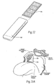
- the magnetic structures 12 and/or 14 can include one or more polymer-bonded magnets 20, as shown in Fig. 4 .
- the polymer-bonded magnet 20 comprises magnetic particles 22 bound within a biocompatible polymer 24.
- the magnetic particles 22 can comprise either isotropic or anisotropic materials, e.g., NdFeB, SmCo, ferrite and/or alnico particles.
- the biocompatible polymer 24 can comprise, e.g., polycarbonate, silicone rubber, polyurethane, silicon elastomer, or a flexible or semi-rigid plastic. Fabric and/or textile and/or ceramic material can also be incorporated within the polymer matrix.
- the magnetic particles 22 are compounded with the biocompatible polymer 24 in a desired proportion.
- the proportion of polymer 24 and magnetic particles 22 in the magnet 20 can be tailored to provide a desired degree of flexibility, elasticity, and magnetic strength.
- the biocompatible polymer 24 is mixed with magnetic particles 22 in a predetermined ratio, and the mixture is compounded (i.e., kneaded). After compounding, the mixture can be molded into a desired shape.
- the molding methods can include, e.g., injection molding, compression molding, extrusion, and calendering.
- the molded component can be cut or machined as needed. Secondary surface coating using other biocompatible polymers may be applied, if desired. Alternatively, or in combination, two-stage molding may be accomplished, during which the molded component is over-molded with a layer of biocompatible polymer.
- the finished component is then magnetized to possess the desired polarity.
- the polymer-bonded magnet 20 is thereby formed as a single piece, which reduces flux leakage.
- the structures 12 and/or 14 could each include a polymer-bonded magnet 20.
- the polymer-bonded magnets 20 implanted in the pharyngeal wall and the tongue would possess like polarity, thereby creating the desired repelling force between them.
- Finite element analysis shows that two repelling polymer-banded magnets 20, each formed as a strip measuring 4mm x 10 mm x 4.0 mm, are capable of creating a maximum energy product of about 0.8 MGOe. Finite element analysis based upon this energy product shows that the two polymer-bonded magnets 20 can generate a repelling force of more than 22 grams/cm 2 when they are positioned 12 mm apart. The magnetic properties of the strips and their dimensions can, of course, be changed to fit the applications.
- the shape of a given polymer-bonded magnet 20 can be selected to best conform to the anatomic site of implantation. It is believed that the biocompatibility, softness, and flexibility of a polymer-bonded magnet 20 make it'tolerable during chronic implantation in.tissue. Larger sizes of a given magnetic structure could also be considered, compared to use of conventional permanent magnets, because of the similar mechanical properties of the polymer-bonded magnet 20 and the surrounding tissue.
- the polymer-bonded magnet 20 can include through holes, and/or non-through holes, and/or complex surface configurations, and/or other surface textures, or combinations thereof, to promote tissue in-growth and implant stability. Further discussion of tissue ingrowth surfaces and materials follows.
- the magnetic structures 12 and/or 14 may include a hybrid magnetic structure 26, as shown in Fig. 5 .
- the hybrid magnetic structure 26 shown in Fig. 5 comprises one or more discrete permanent magnets 28 encapsulated within a polymer-bonded magnetic matrix 30.
- the matrix 30 comprises magnetic particles 22 bound within a biocompatible polymer 24.
- the permanent magnets 28 can comprise sintered, high energy, permanent magnets such as N45 or N48, i.e., possessing a maximum energy product of about 45-48 MGOe. If desired (as shown in Fig. 5 ), one or more threads 34 could connect the magnets 28 within the matrix 30, to improve stability of the structure 32.
- the magnetic particles 22 can comprise either isotropic or anisotropic materials, e.g., NdFeB, SmCo, ferrite and/or alnico particles.
- the biocompatible polymer 24 can comprise, e.g., polycarbonate, silicone rubber, polyurethane, silicon elastomer, or a flexible or semi-rigid plastic. Fabric and/or textile and/or ceramic material can also be incorporated within the polymer matrix.
- the permanent magnets 28 and the magnetic particles 22 are magnetized in the same flux direction.
- the hybrid structure 26 takes advantage of the high magnetic strength of the sintered permanent magnets 28, and combines this benefit with the flexibility and biocompatibility of a polymer-bonded magnetic matrix 30. Furthermore, the presence of the permanent magnetic particles 22 between the high energy permanent magnets 28 pushes the flux lines emanating from the permanent magnets 28 farther away from the surface of the structure 26, as compared to permanent magnets 28 in a pure (non-magnetic) polymer matrix. This change in the flux lines reduces flux leakage.
- Fig. 6 shows an alternative embodiment of a hybrid magnetic structure 32.
- the structure 32 comprises one or more polymer-bonded magnets 20 (as shown in Fig. 4 ) encapsulated within a polymer-bonded magnetic matrix 30, as just described.
- the matrix 30 and the polymer-bonded magnets 20 each comprises magnetic particles 22 bound within a biocompatible polymer 24.
- the density of magnetic particles 22 in the magnets 20 is desirably greater than the density of magnetic particles 22 in the matrix 30. This imparts more flexibility to the low-density matrix 30 and higher magnetic force to the higher density magnets 20. If desired (as shown in Fig. 6 ), one or more threads 34 could connect the higher density polymer-bonded magnets 20 within the matrix 30 to improve stability of the structure 32.
- the magnetic particles 22 can comprise either isotropic or anisotropic materials, e.g., NdFeB, SmCo, ferrite and/or alnico particles; and the biocompatible polymer 24 can comprise, e.g., polycarbonate, silicone rubber, polyurethane, silicon elastomer, or a flexible or semi-rigid plastic. Fabric and/or textile and/or ceramic material can also be incorporated within the polymer matrix.
- the magnetic particles 22 in the magnets 20 and in the matrix 30 are magnetized in the same flux direction.
- the hybrid structure 32 takes advantage of the high density, high performance polymer-bonded magnets 20, and combines this benefit with the flexibility of the low-density polymer-bonded magnetic matrix 30. Furthermore, as described in connection with the hybrid structure 32 in Fig. 5 , the presence of the permanent magnetic particles 22 between the high performance polymer-bonded magnets 20 pushes the flux lines emanating from the polymer-bonded magnets 20 farther away from the surface of the structure 32, as compared to polymer-bonded magnets 20 in a pure (non-magnetic) polymer matrix. This change in the flux lines reduces flux leakage.
- the structures 12 and/or 14 could each comprise one of the hybrid magnetic structure 26 and/or 32.
- the structures 26 and/or 32 implanted in the pharyngeal wall and the tongue would possess like polarity, thereby creating the desired repelling force between them.
- hybrid magnetic structure 26 or 32 can be selected to best confirm to the anatomic site of implantation. Furthermore, either hybrid magnetic structure 26 or 32 can include through holes 36 (see Fig. 7 ), and/or non-through holes, and/or complex surface configurations 38 (see Fig. 8 ), and/or other surface textures, or combinations thereof, to promote tissue in- growth and implant stability.
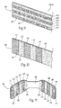
- the magnetic structures 12 and/or 14 could include a layered magnetic structure 40, as shown in Fig. 9 .
- the layered structure 40 comprises two or more' layers of magnetic particles 22 encapsulated in different densities within a biocompatible polymer 24.
- six layers L1 to L6 are shown for purposes of illustration, and it should be appreciated the number of layers can be greater than or less than, six.
- the density of magnetic particles 22 in layers L1, L3, and L5 is greater than the density of magnetic particles 22 in the neighboring layers L2, L4, and L6.
- the presence of the less dense layers L2, L4, and L6 imparts overall flexibility to structure 40, whereas the presence of the more dense layers L1, L3, and L5 imparts higher magnetic force.
- the juxtaposition of the less dense layers L2, L4, and L6 between the more dense layers L1, L3, and L5 pushes the flux lines emanating from the higher density layers L1, L3, and L5 farther away from the surface of the structure 40, as compared to uniform density polymer-bonded magnetic layers. This change in the flux lines reduces flux leakage.
- the magnetic particles 22 can comprise either isotropic or anisotropic materials, e.g., NdFeB, SmCo, ferrite and/or alnico particles; and the biocompatible polymer 24 can comprise, e.g., polycarbonate, silicone rubber, polyurethane, silicon elastomer, or a flexible or semi-rigid plastic. Fabric and/or textile and/or ceramic material can also be incorporated within the polymer matrix.
- the magnetic particles 22 in the layers L1 to L6 are magnetized in the same flux direction.
- the density of magnetic particles 22 in the higher density layers L1, L3, and L5 is shown to be generally the same.
- the density of magnetic particles 22 in the higher density layers L1, L3, and L5 can gradually increase. This provides a change in the flux density across the surface of the structure 40.
- the structures 12 and/or 14 could each comprise a layered magnetic structure 40, or a layered magnetic structure 40 used in combination with another type of magnetic structure, such as a flexible array of discrete permanent magnets, polymer-bonded magnets, or hybrid magnetic structures 26 and/or 32. Regardless, the structures 12 and 14 implanted in the pharyngeal wall and the tongue would possess like polarity, thereby creating the desired repelling force between them.
- the shape of a layered magnetic structure 40 can be selected to best confirm to the anatomic site of implantation.
- the layered structure 40 can comprise end portions 44 separated by a connecting strip 46.
- Each end portion 44 includes the layers L1 to L6 of magnetic particles 22 encapsulated in different densities within a biocompatible polymer 24, as previously described.
- the layers L1 to L6 could provide a variation of densities, or the density of magnetic particles 22 within one or both end portions 44 could be uniform.
- the connecting strip 46 comprises the biocompatible polymer 24 free of magnetic particles 22.
- the magnetic particles 22 in the end portions 44 are magnetized to have the same polarity, so that the end portions repel each other.
- the intermediate strip 44 being free of magnetic particles 22, does not interfere with the repelling force.
- the structure 40 can include surface texturing (shown as a pattern of non-through holes H), to promote tissue in-growth and implant stability.
- Through holes as shown in Fig. 7
- complex surface configurations as shown in Fig. 8
- other surface textures or combinations thereof, can be used for the same purpose.
- a way to achieve this objective is to include means for focusing the magnetic flux in a desired direction, while also reducing the flux in other directions.
- the focusing of magnetic flux can make possible the use of smaller magnets.
- the focusing of magnetic'flux can also impart stability to the implanted structure, to resist migration within tissue.
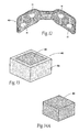
- Fig. 13 shows a magnetic structure 46 comprising a magnetic core 48 and an overlaying flux shield 50 that includes a soft ferromagnetic material.
- the magnetic core 48 can comprise a polymer-bonded magnet, or a hybrid magnetic structure, or a layered magnetic structure, all having previously been described.
- the soft ferromagnetic material of the flux shield 50 has very high permeability and saturation magnetization, but very low intrinsic coercivity. Examples of known soft ferromagnetic materials include Iron (Fe); Nickel (Ni); Permendur; MuMetal, low-carbon steels, Iron-Cobalt alloys (Fe-Co); silicon steels; and amorphous alloys.
- a flux shield 50 of a soft ferromagnetic material focuses and enhances the magnetic field of the core 48 in directions that the shield 50 does not overlay.
- the flux shield 50 overlays all but one pole of the core 48.
- the flux shield 50 need overlay only one pole surface of the core 48 to achieve a flux focusing effect
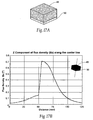
- Fig. 14A shows a core 48 comprising a permanent magnet measuring 40 mm x 40 mm x 25 mm (i.e., a volume of 40,000 mm 3 ).
- Fig. 14B shows the total flux density distribution on the YZ plane, based upon finite element modeling, of the magnetic field generated by the permanent magnet.
- Fig. 14B shows the magnetic field emanating in all directions in the YZ plane about the magnet.
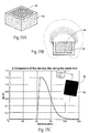
- Fig. 14C shows the magnitude of the Z component of flux density (Bz) taken at increasing/distances from the top magnet surface along its center line.
- Fig. 14C generally shows a bell shaped curve, with a maximum Bz(T) of 0.6 at a distance of about 62 mm from the magnet surface, with gradual increases with decreasing distances and gradual decreases with increasing distances.
- Fig. 15A shows a core 48 comprising a permanent magnet smaller than the magnet of Example 1, measuring 30 mm x 30 mm x 20 mm (i.e., having a lesser volume of 18,000 mm 3 ), The magnet has been placed within a flux shield 50.
- the flux shield comprises a box made from a soft ferromagnetic material: The box covers all but one pole surface of the permanent magnet.
- Fig. 15B shows the total flux density distribution on the YZ plane, based upon finite element modeling, of the magnetic field generated by the permanent magnet when housed within the box.
- Fig. 15B shows that the presence of the ferromagnetic material of the box significantly alters the distribution pattern of the flux density of the field on the YZ plane.
- the magnetic field is demonstrably focused in the direction of the field that is not shielded by the ferromagnetic material.
- Fig. 15C shows the magnitude of the Z component of flux density (Bz) taken at increasing distances from the unshielded pole surface along its center line.
- Fig. 15C confirms the focused nature of the magnetic field.
- FIG. 15C also shows an increase in the flux density of the Z component in Example 2, despise the use of a magnet of significantly lesser volume than in Example 1.
- the curve in Fig. 15C is not bell shaped.
- the Z component of the flux density BZ suddenly spikes at a maximum Bz(T) of 1.2 at a distance of about 55 mm from the unshielded pole, and thereafter maintains a magnitude above 0.6 Bz(T) - i.e., above the maximum flux density of the' Z component of Example 1 - at increasing distances up to about 75 mm from the single unshielded pole of the magnet.
- FIG. 14B /C A comparison of Figs. 14B /C with Figs. 15B /C demonstrates the ability of a soft ferromagnetic material to shield and to focus the magnetic field emanating from a permanent magnet.
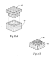
- Figs. 16A and 16B show alternative arrangements of magnetic cores 48 comprising permanent magnets with flux shields 50 of soft ferromagnetic materials. Finite element analysis of these alternative arrangements show the focused flux density distribution shown in Fig. 15B , as well as the spike-curve configuration, shown in Fig. 15C , of the Z component of flux density (Bz) taken at increasing distances from the unshielded magnet pole along its center line.
- Fig. 17A shows magnetic core 48 comprising a permanent magnet having generally the same measurements as the magnet in Example 1.
- the flux shield 50 overlays only one pole of the magnet.
- Fig. 17B shows that the magnitude of the Z component of flux density (Bz) taken at increasing distances from the unshielded magnet pole along its center line has been altered by the presence of the single pole flux shield 50
- Fig. 17B shows the same spike-curve configuration shown in Fig. 15C , demonstrating that the presence of the single pole flux shield 50 has focused the magnetic field in the direction of the unshielded magnet pole.
- Fig. 17B also demonstrates that the maximum strength of the magnetic field has likewise been increased, from 0.6 Bz(T) in Example 1 to 0.7 Bz(T) in Example 4.
- Fig. 17B demonstrates the ability of single pole flux shield 50 of soft ferromagnetic material to shield and focus the magnetic field emanating from a permanent magnet.
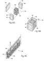
- FIGS. 18A and 18B show a stabilized magnetic structure 52 comprising a magnetic core 54 joined to a pair of stabilizing magnets 56.
- the magnetic core 54 can comprise a rare earth permanent magnet, or a polymer-bonded magnet, or a hybrid magnetic structure, or a layered magnetic structure, all having previously been described.
- the magnetic core 54 has a repelling pole 58 that is sized and configured to be primarily responsible for the repelling force needed for a given structure.
- Each stabilizing magnet 56 is secured to a side of the repelling magnetic core 54, e.g., by adhesive, welding, molding, crimping, or soldering.
- the stabilizing magnets 56 comprise rare earth permanent magnets, or a polymer-bonded magnet, or a hybrid magnetic structure, or a layered magnetic structure, all having previously been described.
- the stabilizing magnets 56 each has a repelling pole 60 (i.e., having the same polarity as the repelling pole 58).
- the surfaces of the repelling poles 60 of the stabilizing magnets 56 are oriented at right angles to the repelling pole 58 of the magnetic core 52.
- the poles 60 of the permanent stabilizing magnets 56 like the repelling pole 58 of the magnetic core 52, are all like the poles of the magnet(s) on the opposing magnetic structure.
- the outward facing poles 60 of the permanent stabilizing magnets 56 will, to a greater or lesser degree, continue to farce the like poles of the magnet(s) on the other magnetic structure. Since the outward facing poles 60 of the permanent stabilizing magnets 56 are like the poles of the other structure, the repelling nature of magnetic field between the two structures remains the same - the two magnet structures 12 and 14 continue to repel each other. Rotational misalignment may lead to a diminution of the magnetic force field, but the magnetic force field is itself still a repelling field. Destabilizing magnetic fiends are reduced due to misalignment, to reduce twisting or otherwise destabilizing either structure 12/14.
- the stabilized magnetic structure 52 may includes a shielding pole piece 62 made of a soft ferromagnetic material secured to the opposite pole face of the magnetic core 54.
- the shielding pole piece 62 serves to alter the distribution and the magnitude of the Z component of flux density (Bz), in the manner previously demonstrated, providing the spike-shaped performance characteristic shown in Fig. 17B .
- the shielding pole piece 62 focuses the magnetic flux in the desired direction.
- the repelling magnetic core 54 has a dimension of 2 mm x 2mm x 4mm.
- Each stabilizing magnet 56 has a dimension of 1 mm x 2 mm x 4 mm.
- the shielding pole piece 62 has a dimension of 4 mm x 4mm x 0.5 mm.
- the resulting structures 52 can be assembled into arrays 64 of stabilized magnetic structures 52 (see Fig. 18C ). On each array 64, the stabilized magnetic structures 52 are spaced apart by about 1 mm. Arranged in a facing, repelling relationship at a distance of about 12 mm, finite element analysis shows that a repelling force between the arrays 64 can be generated, which can be increased or decreased by changing the dimensions of the stabilized magnetic structures 52 or the arrays 64.
- the presence of the shielding pole piece 62 focuses and increases the flux density in the desired direction between arrays 64.
- the presence of the stabilizing magnets 56 provides positional stability, to which the shielding pole piece 62 also contributes by reducing flux density in undesired directions.
- the array 64 include more than one row of adjacent magnetic structures 52 with stabilizing magnets 56, the surfaces of the magnetic structures 52 that face inward within the array 64 need not carry stabilizing magnets 56.
- the stabilizing magnets 56 are located along the outside edges of the multiple row array 64.
- Positional stability of a given array of magnets can also be enhanced without use of stabilizing magnets 56.
- magnetic cores 54 comprising e.g., rare earth permanent magnets, or polymer-bonded magnets, or hybrid magnetic structures, or layered magnetic structures
- Each magnetic core 54 has a repelling pole 58 that is sized and configured for the repelling force needed for a given structure.
- Enhanced positional stability in such an array can be achieved by reorienting a repelling pole 56 of one of the magnetic cores 54 by ninety-degrees, in either direction (shown, respectively, in Figs.
- one or more cores 54 can be reoriented in this manner in either a random or repeating pattern. Should rotational misalignment of one magnetic array relative to another magnetic array occur, the presence of at least one reoriented core within one or both of the arrays will, to a greater or lesser degree, maintain the repelling nature of the magnetic field between the two structures. Destabilizing Magnetic fields are reduced due to misalignment, to reduce twisting or otherwise destabilizing either array.
- Implants of the types described herein can be fixed percutaneously into the pharyngeal wall and/or tongue (the locations shown in Fig. 2 ), and/or elsewhere in the pharyngeal conduit, and/or elsewhere in the body in various ways.
- the position of implanted magnetic structures 12/14 can be fixed against migration in a targeted tissue region, e.g., within the pharyngeal conduit, using conventional mechanical fixation materials and techniques known in the surgical arts, e.g., resorbable or non-resorbable sutures, screws, staples, darts, clips, adhesives, or glues such as cyanoacrylate, or cements such as polymethyl methacrylate (PMMA) cement.
- the structures 12/14 can include preformed apertures to accommodate the' fixation material, i.e., suture, screw, staples, darts, or clips. Fixation to tissue enhances the fixation function of the implanted structure.
- the tissue to which a given implant is fixed can include soft tissue, such as mucosa, submucosa, fascia, or muscle in the pharyngeal walls, the base of the tongue; the vallecula; the soft palate with uvula; the palatine tonsils with associated pillar tissue, and the epiglottis.
- soft tissue such as mucosa, submucosa, fascia, or muscle in the pharyngeal walls, the base of the tongue; the vallecula; the soft palate with uvula; the palatine tonsils with associated pillar tissue, and the epiglottis.
- the tissue can also include bone within the pharyngeal conduit, e.g., a hyoid bone or a vertebra.
- a given magnetic structure or implant can be implanted in either a horizontal or vertical anatomic orientation, and/or in a linear or curvilinear pattern within the pharyngeal conduit or elsewhere in the body.
- Implants can be placed directly within the mucosa, or the submucosa, or against the fascia, or against or within muscle within the pharyngeal wall and/or tongue (the locations shown in Fig. 2 ) or elsewhere in the body by raising a surgical flap.
- the flap approach can be accomplished in a single stage or in two stages. Either approach can be used to place a magnetic structure in the pharyngeal conduit or elsewhere in the body.
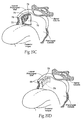
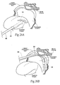
- Figs. 19A to 19D show the use of a single stage flap approach to place an implant in a lateral pharyngeal wall.
- Figs. 20A to 20D show the use of single stage flap approach to place an implant in a posterior-lateral pharyngeal wall.
- Figs. 21A to 21D show the use of a single stage flap approach to place an implant in a posterior region of a tongue.
- a flap 70 is formed in the tissue plane (see Figs. 19A , 20A , and 21A ).
- the flap 70 is formed by using an appropriate surgical cutting instrument to form an incision having a desired shape.
- the formed flap 70 can be of various shapes and positions depending on the desired location, shape and proposed function of the implant.
- bilateral pharyngeal wall flaps 70 can be configured in a curvilinear upside down "L" shape for placement of directly opposite implants.
- a superior or inferior based "U" shaped flap can be configured along the posterior and posterior-lateral pharyngeal walls for placement of two posterior-lateral implants either connected or not across the midline. Tongue flaps of similar configurations can likewise be elevated.
- Elevating a flap 70 can expose underlying muscle 72 (see Figs. 19B , 20B , and 21C ), which can be fascial covered. Excellent exposure is afforded for controlled placement of the implants.
- the pharyngeal flaps (both lateral and posterior-lateral) can expose pharyngeal constrictor muscles, and the tongue flap can expose genioglossal muscle,
- a selected implant 74 is then stabilized within the mucosa, or the submucosa, or against the fascia or against or within muscle 72 in each elevated flap 70, e.g., with simple sutures 76, and/or mattress sutures, and/or staples, and/or clips, and/or darts, and/or hooks or fasteners attached to or formed on the biocompatible body of the structure (which can be biodegradable, if desired).
- the implant 74 is desirably dipped or impregnated with an ' antibiotic.
- bone anchors 78 placed into the anterior vertebral column can be used.
- a surgical pocket can be formed to receive the implant:
- the pocket is formed by dilating tissue by use of a trocar or expandable dissector, to open a tissue space to receive an implant.
- a pocket approach like the flap approach, no sutures need to be placed through the mucosa into the implant.
- the implantation and implant fixation techniques described herein with regard to a surgical flap apply to surgical pockets as well.
- the flaps 70 can be closed, e.g., with one or more absorbable or non-absorbable sutures 80, adhesives, or glues such as cyanoacrylate, or cements such as polymethyl methacrylate (PMMA) cement.
- An absorbable suture 80 can be rapidly dissolving (e.g., seven days), or comprise a longer lasting absorbable suture such as VicrylTM material, Supplemental systemic antibiotics are desirably utilized, which can be delivered into the flap 70 (or pocket) before or after implant placement.
- Agents to stimulate rapid fibrosis can be used for further stabilisation.
- agents include fibrin sealants, tissue sealants, talc (dry or slurry), doxycycline, bleornycin, povidone iodine, minocycline, doxorubicin, streptokinase, urokinase, sodium tetradecyl sulfate, and/or silver nitrate.
- Other coatings to promote the stability of the implant 74 include calcium hydroxylapatite, aluminum oxide, bioactive hydroxy apatite, or tricalcium phosphate.
- Such agents can be applied only at pre-selected locations on the implant 74, e.g., such as bottom and side boundaries, to leave easy access to the top portion of the implant 74 for removal.
- such agents can be injected directly into the flap 70 (or pocket), or may used to irrigate the flap 70 (or pocket), or may be placed within a gel or hydrogel in the flap 70 (or pocket).
- Tissue adhesives, fibrin sealants, and glues such as cyanoacrylate, or cements such as polymethyl methacrylate (PMMA) cement can be applied to either improve stabilization or replace mechanical sutures or fasteners.
- a tissue ablation agent or energy source may be used to form avascular pockets.
- Tissue ingrowth materials can also be used, as will be described in greater detail later.
- pharyngeal flaps 70 can be formed in the manner just described, which can expose pharyngeal constrictor muscles 72 or genioglossal muscle 72, which can be fascial covered.
- Fig. 23A shows, for purpose of illustration, the flap being formed in a lateral pharyngeal wall. Alternatively, a surgical pocket can be formed.
- a modular receptacle 82 or sleeve (see Fig. 22 ) is then stabilized, e.g., within the muscosa, or against the fascia, or against or within muscle, in each flap 70 (see Fig. 23B ) (or pocket), with resorbable or non-resorbable sutures, and/or staples, and/or hooks and/or fasteners, and/or darts, and/or clips, and/or screws, and/or adhesives, and/or glues such as cyanoacrylate, or cements such as polymethyl methacrylate (PMMA) cement.
- PMMA polymethyl methacrylate
- the flaps 70 are then closed with non-absorbable or absorbable suture 80, adhesives, or glues such as cyanoacrylate, or cements such as polymethyl methacrylate (PMMA) cement.
- Supplemental systemic antibiotics are desirably utilized.
- the implanted receptacle 82 is allowed to stabilize within the flap or pocket by fibrous capsule formation or tissue ingrowth.
- agents can be used to stimulate rapid fibrosis in tissue surfaces, and/or tissue sealants, adhesives, and/or glues can be applied to either improve stabilization or replace mechanical sutures or fasteners; and/or tissue ablation agents or energy sources can be applied to form avascular pockets, and/or tissue ingrowth materials can be used, as will be described in greater detail later.
- a selected implant 74 is loaded into the receptacle 82 (see Fig. 23D) . This can be done, e.g., by re-opening a portion of the flap or pocket, or the use of transmucosal trochars.
- the two stage approach allows stabilization of a basic implant support (i.e., the receptacle 82) to occur within a flap or pocket prior to the introduction of the operative implant 74, e.g., one subject to magnetic forces or another potentially destabilizing force.
- the two stage approach also allows one to titrate, e.g., magnetic force requirements to the individual patient's needs without replacing the basic implant support.
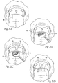
- Implants of the types described herein can also be placed percutaneously into the pharyngeal wall and/or tongue (the locations shown in Fig. 2 ) or elsewhere in the body by use of percutaneous instrument systems 84, without opening a flap or another incision site.
- An instrument system 84 may be variously constructed.
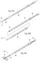
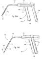
- Figs. 24A to 24C show a representative system 84.
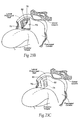
- the system 84 includes an access cannula 86 which, in use, can be deployed within the oral cavity to create a percutaneous path to a selected implantation site either in a tongue (see Fig. 26A ) or in a pharyngeal wall (see Fig. 26B ).
- a trocar-tip guide wire 90 can be used to initially puncture the targeted tissue site.
- a cannulated tissue plane dissector 88 can then be passed over the guide wire 90 to create an entry site to the tissue and to separate the tissue layers at the implantation site.
- the guide wire 90 can then be removed, and the access cannula 86 can be passed over the dissector 88 to the implantation site.
- the dissector 88 and guide wire 90 are removed, to open a working channel through the access cannula 86 to the implantation site.
- the dissector 88 and access cannula 86 can be deployed nested together, being passed as a unit into tissue, with or without use of a guide wire.
- the blunt tip of the dissector 88 projects beyond the distal end of the cannula 86, serving to open an entry site and separate the tissue layers at the implantation site.
- the dissector 88 can then be removed from the cannula 86, to open the working channel.
- another instrument may be deployed through the working channel of the cannula 86, if necessary, to create a surgical pocket in the tissues to receive the implant.
- the system 84 may include a implant delivery tool 92.
- the tool 92 carries an implant 94 in a preloaded condition within its distal end.
- the tool 92 is passed through the working channel of the cannula 86 to the implantation site.
- a plunger 96, or rod, abuts against the implant.
- the implant can be expelled from distal end of the tool 92 into the prepared implantation site (see Fig. 24C ).
- the cannula 86 and the implant delivery tool 92 can, at the appropriate time, be removed as a unit, leaving the implant behind.
- the implant 94 can be loaded directly into the proximal end of the cannula 86, and the plunger 96 passed through the cannula 86 to advance the implant to the distal tip of the cannula 86. Holding the plunger stationary and pulling back on the cannula 86 expels the implant into the prepared implantation site. The cannula 86 and plunger 96 can then be removed as a unit, leaving the implant behind.
- a given implant 94 may be rolled or folded within the working channel of the cannula 86 or within the delivery tool 92 during deployment.
- the implant 94 can include a material than actively or passively reshapes the implant 94 into its in-use condition after deployment into the implantation site.
- the material may urge the implant 94 toward a lay-flat or curvilinear in-use condition when free of the cannula 86.
- the material may possess a spring constant or include a shape memory to self-expand to the desired lay-flat or curvilinear in-use condition.
- the implant 94 may be deployed in conjunction with a shaping member that actively reshapes the implant 94 into it in-use condition after deployment from the cannula 86.
- the implant 94 may be wrapped around an expandable structure that expands or inflates to force the implant to flatten.
- the implant 94 may be wrapped around a mechanically expanding member that transoms linear or rotational motion into motion that will lay out the implant 94.
- the cannula 86 is shown to be cylindrical in shape, and the other tools that pass through the working channel are correspondingly shaped.
- the shape can be cylindrical, oval, rectilinear, or other configurations.
- the shape of the delivery tools may be customized to the shape of the implant 94 itself.
- the implant 94 comprises a rectilinear shape
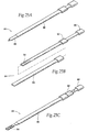
- the working channel itself can be correspondingly rectilinear in cross section, as Figs. 25A to 25C show.
- the rectangular cannula 86 and the rectangular dissector 88 form a combination tool 98, which can be manipulated to gain access to the tissues.
- the tool 98 nests the dissector 98 within the cannula 86.
- the dissector 98 takes the form of a sharp, inner stylet with a trocar or blade tip that can puncture the tissue.
- the cannula 86 takes the form of an outer stylus holding the dissector 98.
- the combination tool 98 punctures the tissue; after which the dissector 88 is withdrawn from the cannula 86. If it is necessary to form a pocket within the tissue, another blunt tip instrument may be passed through the working channel of the cannula 86 to further separate the tissue layers.
- a rectangular implant 94 is loaded into a rectangular delivery tool 92.
- the delivery tool 92 is passed through the working channel of the cannula 86 to the site that has been prepared for implantation.
- a rectangular plunger 96 is advanced through the delivery tool 92 to expel the implant 94 from the tool 92 into the implantation site.
- the implant 94 may or may not be further anchored to the underlying tissues/muscle layer.
- the position of the implant 94 may be stabilized using a suitable stabilization element, e.g., one or more staples, and/or clips, and/or darts, and/or sutures, and/or medical adhesives or glues, as previously described. Stablization can be achieved without fixation of the implant to mucosa or submucosa tissue, if desired.
- Tools that place the stabilizing element in the implant 94 may be an integrated part of the access cannula or implant delivery tool, or may comprise one or more separate tools that are themselves deployed through the working channel of the cannula 86, or may comprise one or more tools that are deployed by some other means.
- the working channel of the cannula 86 can also be used to flush the delivery site with antibiotic solutions prior to, during, and after implant delivery.
- antibiotic solutions can include, e.g., chlorohexalin, kanamicin, Baytril, cephalexin, or gentamicin.
- the cannula and other tools of the system can be made of metal, plastic, or ceramic materials, or combinations thereof.
- the cannula and other tools can be made of flexible materials, allowing the instruments to be flexed or shaped during use (as Fig. 26B shows for purposes of illustration).
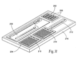
- the implant 94 can carry integrated stabilization elements 100 that automatically anchor the implant to tissue when it is released into the implantation site.
- Stabilization elements 100 can be integrated to the implant in various ways.
- the tissue stabilization elements 100 are carried at the end of elastic arms 102 and 104, having spring-like characteristics.
- the elastic arms 102 and 104 are secured at opposite ends of the implant 94, and they occupy different planes.
- the elastic arms 102 are secured along the front surface of the implant 94, and the elastic arms 104 are secured along the rear surface of the implant 94. This arrangement balances the stabilizing forces about the implant 94, as well as facilitates the deployment of the elements 100 in the first instance.
- the elastic arms 102 and 104 may be made of shape memory plastic or metallic materials that expand within the plane of the implant 94 or outside the plane of the implant 94.
- the elastic arms 102 and 104 are placed into compression and bent inward toward the implant 94, into what can be called an inboard condition, when the implant 24 is confined within the delivery tool 92 (see Fig. 30C ). When free of the confines of the delivery tool 92 (see Figs. 30A and 30D ), the arms 102 and 104 spring outward from the implant 94, due to their spring-like characteristics, into what can be called an outboard condition, engaging tissue.
- the distal end of the delivery tool 92 includes opposing slots 106 that align with the elastic arms 102 on the trailing edge of the implant 94 (i.e., the edge that is last to exit the tool 92 during implant deployment).
- the elastic arms 104 on the leading edge of the implant 94 i.e., the edge that is first to exit the tool 92 during implant deployment) do not align with the slots 106.
- the implant 92 is loaded into the tool 92, trailing edge first, with the elastic arms 102 and 104 in their outboard condition.
- the slots 106 accommodate passage of the elastic arms 102 on the trailing edge of the implant 92, as the implant is progressively loaded into the tool 92.
- the elastic arms 102 on the trailing edge of the implant 92 will abut the terminus 108 of the slots 104 about the same time that as the elastic arms 104 on the leading edge of the implant 92 abut the distal terminus 110 of the tool 92.
- Loading the implant 92 further into the tool 92 results in resiliently bending the elastic arms 102 and 104 progressively forward into their inboard condition.
- the slot terminus 108 will deflect the elastic arms 102 forward into compression, and the end terminus 110 will deflect the elastic arms 104 forward into compression.
- the walls of the tool 92 keep the elastic arms 102 and 104 in compression in their inboard condition.
- the plunger 96 is held stationary, and the tool 92 is drawn away from the implantation site. This will release the implant 92 from the confines of the tool 92, leading edge first. As the leading edge of the implant clears the tool 92, the arms 104 will spring outward to their outboard condition (see Fig. 30D ). As the trailing edge of the implant clears the tool 92 (as Fig. 30A shows), the arms 102 will spring outward to their outboard condition.
- the self-deployed stabilization elements 100 anchor the implant 94 in adjacent tissue, without need for deployment of a separate stabilization tool.
- FIGs. 27A and 27B show a hand-held tool 112 comprising a delivery cannula 114 coupled by a flexible tubing 116 to a handle 118.
- An implant 94 is carried within the cannula 114.
- the cannula 114 includes a needle-like, tissue penetrating distal tip 122.
- the distal tip 122 can be placed into tissue in the tongue or pharyngeal wall, while the handle 118 remains fully or partially inside the oral cavity.
- a plunger 118 abuts against the trailing edge of the implant 94.
- the plunger 118 is coupled by a push-pull cable (which passes through the tubing 116) to an actuator 120 on the handle 114. Pushing forward on the actuator 120 advances the plunger 118 (see Fig. 27B ), which expels the implant from the cannula 114 into the implantation site.
- the actuator 120 takes the form of a trigger mechanism 124, which can be actuated by squeezing a slidable aft trigger member 126 toward a stationary forward handle 128, or by pulling a pivot trigger 130 (shown in phantom lines) toward the handle 128.
- the actuator 120 takes the form of a sliding thumb lever 132.
- a given implant can include a tissue in-growth surface 70 (see Fig. 2 ).
- tissue in-growth surface 70 has previously been described in association with the polymer-bonded, hybrid, and layered magnetic structures.
- the surface 70 provides an environment that encourages the in-growth of neighboring tissue on the implanted structure.
- Tissue in-growth is defined as the filling of pores in an implanted material with cellular material. As in-growth occurs, the implanted structure 12 will become securely anchored, resisting migration or extrusion from the tissue.
- the tissue in-growth surface 70 thus enhances tissue adhesion and stabilization, and thereby further stabilizes and fixes the position of the implanted structure 12 in the targeted implantation site.
- the tissue in-growth surface 70 can be formed in various ways, such as the porous nature of the material, knitting, weaving, through holes, or molding a porous structure or surface.
- suitable materials include polytetrafluo-roethylene (PTFE), expanded PTFE, polyethylene terephthalate such as Dacron ® (PET) fabric, other permanent polyesters, polyurethane, silicone, polypropylenepolyvinyl alcohol, biodegradeable polyesters such as polylactic acid and polyglycolic acid.
- Anchoring may be accomplished by use of resorbable or non-resorbable sutures, screws or other mechanical fasteners made of resorbable or non-resorbable materials such as polyglycolic acid or other similar compounds.
- Tissue adhesives and/or tissue cements such as PMMA and/or tissue sealants, and/or tissue glue such as cyanacrylate may also be used to provide tissue adhesion, fixation, and stabilization.
- Complete tissue in-growth is determined by the percentage of the material that has been infiltrated by the cellular material. With pore sizes from 100 micrometers to 500 micrometers, blood vessels can be formed. With pore sizes of 10 micrometers to 100 micrometers, cells to small capillaries can form.
- materials or shapes may be used that encourage tissue or fibrotic encapsulation of the implant 94, with or without tissue ingrowth.
- system 200 that can provide treatment for dysfunctions affecting the pharyngeal conduit, such as sleep disordered breathing, snoring, or sleep apnea.
- the system 200 would have an implant component 202 and an implantation component 204.
- the implant component 202 can include providing one or more implants 206 that are sized and configured to be implanted in a targeted tissue region comprising at least one pharyngeal structure or at least one anatomic component within a pharyngeal conduit.
- implants 206 having this characteristic have been described herein.
- the system 200 desirably includes an implantation component 204, because of challenges that are presented in the placement of implants 206 in the dynamic tissue environment of the pharyngeal conduit.
- the implantation component 204 includes providing at least one tool 208 and/or instructions 210 for placing the implant 206 in a tissue region, e.g., through a percutaneous access path, using the tools described herein and shown in Figs. 24 to 30 ; or by forming a surgical flap as described herein and shown in Figs. 19 to 23 ; or by forming a surgical pocket, , as also described herein.
- the implantation component 204 can also include providing at least one tool 212 and/or instructions 214 for stabilizing the implant within a mucosa, or a submucosa, or against a fascia, or against or within a muscle, as described herein.
- the tool 212 and/or instructions 214 can make possible the stabilization of the implant against submucosa, or a fascia, or against or within a muscle, without stabilizing through a mucosa, as described herein.
- Other tools and instructions can be provided, e.g., to make various mechanical fixation materials (as described herein) accessible; or to make agents that stimulate rapid fibrosis (as described herein) available; or to provide antibiotic materials (as described herein).
- the basic components 202 and 204 of the system 200 can be provided individually, or packaged in the form of a kit 216, as Fig. 31 shows.
- the various instructions can be in written form, electronic form, or verbal form, which can be provided in the kit 216 and/or as part of a training program or web site for clinicians.
Landscapes
- Health & Medical Sciences (AREA)
- Life Sciences & Earth Sciences (AREA)
- Engineering & Computer Science (AREA)
- Veterinary Medicine (AREA)
- Public Health (AREA)
- General Health & Medical Sciences (AREA)
- Animal Behavior & Ethology (AREA)
- Biomedical Technology (AREA)
- Vascular Medicine (AREA)
- Heart & Thoracic Surgery (AREA)
- Pulmonology (AREA)
- Chemical & Material Sciences (AREA)
- Oral & Maxillofacial Surgery (AREA)
- Pharmacology & Pharmacy (AREA)
- Nuclear Medicine, Radiotherapy & Molecular Imaging (AREA)
- Medicinal Chemistry (AREA)
- General Chemical & Material Sciences (AREA)
- Chemical Kinetics & Catalysis (AREA)
- Orthopedic Medicine & Surgery (AREA)
- Cardiology (AREA)
- Organic Chemistry (AREA)
- Transplantation (AREA)
- Nursing (AREA)
- Bioinformatics & Cheminformatics (AREA)
- Otolaryngology (AREA)
- Anesthesiology (AREA)
- Neurology (AREA)
- Neurosurgery (AREA)
- Prostheses (AREA)
- Orthopedics, Nursing, And Contraception (AREA)
- Respiratory Apparatuses And Protective Means (AREA)
Description
- The invention is directed to a system, that fixates or braces tissue in targeted body regions, e.g., in the pharyngeal conduit for the treatment of sleep disordered breathing including obstructive sleep apnea.
- First described in 1965, sleep apnea is a breathing disorder characterized by brief interruptions (10 seconds or more) of breathing during sleep. Sleep apnea is a common but serious, potentially life-threatening condition, affecting as many as 18 million Americans.
- There are two types of sleep apnea: central and obstructive. Central sleep apnea, which is relatively rare, occurs when the brain fails to send the appropriate signal to the breathing muscles to initiate respirations, e.g., as a result of brain stem injury or damage. Mechanical ventilation is the only treatment available to ensure continued breathing.
- Obstructive sleep apnea (OSA) is far more common. It is one of the several entities that make up the broader group of sleep disordered breathing (SDB). This group of disorders ranges from habitual snoring to OSA. Normally, the muscles of the upper part of the throat keep the airway open to permit air flow into the lungs. When the muscles of the upper airway relax and sag, the relaxed tissues may vibrate as air flows past the tissues during breathing, resulting in snoring. Snoring affects about half of men and 25 percent of women - most of whom are
age 50 or older. - In more serious cases, the airway becomes blocked, making breathing labored and noisy, or even stopping it altogether. In a given night, the number of involuntary breathing pauses or "apneic events" can be quite frequent. These breathing pauses are almost always accompanied by snoring between apnea episodes, although not everyone who snores has OSA.
- Lack of air intake into the lungs results in lower levels of oxygen and increased levels of carbon dioxide in the blood. The altered levels of oxygen and carbon dioxide alert the brain to resume breathing and cause arousal. The frequent interruptions of deep, restorative sleep often lead to early morning headaches, excessive daytime sleepiness, depression, irritability, and learning and memory difficulties.
- The medical community has become aware of the increased incidence of heart attacks, hypertension and strokes in people with moderate or severe obstructive sleep apnea. It is estimated that up to 50 percent of sleep apnea patients have high blood pressure.
- Upon an apneic event, the sleeping person is unable to continue normal respiratory function and the level of oxygen saturation in the blood is reduced. The brain will sense the condition and cause the sleeper to struggle and gasp for air. Breathing will then resume, often followed by continued apneic events. There are potentially damaging effects to the heart and blood vessels due to abrupt compensatory swings in blood pressure. Upon each event, the sleeping person will be partially aroused from sleep, resulting in a greatly reduced quality of sleep and associated daytime fatigue.
- Although some apneic events are normal in all humans, the frequency of blockages will determine the seriousness of the disease and opportunity for health damage. When the incidence of blockage is frequent, corrective action should be taken.
- As Figs. 1A and 1B show, the upper airway consists of a conduit that begins at the nasal valve, situated in the tip of the nose, and extends to the larynx. Although all tissue along this conduit is dynamic and responsive to the respiratory cycle, only the pharyngeal conduit structures -- the tissues in the region of the airway that starts behind the nasal cavity and ends in its connections to the supraglottic larynx -- is totally collapsible. The pharyngeal structures and individual anatomic components within this region include the pharyngeal walls; the base of the tongue; the vallecula; the hyoid bone and its attachments; the soft palate with uvula, the palatine tonsils with associated pillar tissue; and the epiglottis.
- The cross sectional area of the upper airway varies with the phases of the respiratory cycle. At the initiation of inspiration (Phase I), the airway begins to dilate and then to remain relatively constant through the remainder of inspiration (Phase II). At the onset of expiration (Phase III) the airway begins to enlarge, reaching maximum diameter and then diminishing in size so that at the end of expiration (Phase IV), it is at its narrowest, corresponding to the time when the upper airway dilator muscles are least active, and positive intraluminal pressure is lowest. The upper airway, therefore, has the greatest potential for collapse and closure at end-expiration. Schwab RJ, Goldberg AN. Upper Airway Assessment: Radiographic and other Imaging Techniques. Otolaryngol Clin North Am 1998; 31:931-968.
- Sleep is characterized by a reduction in upper airway dilator muscle activity. For the individual with obstructive sleep apnea (OSA) and perhaps the other disorders which comprise much of the group of entities called obstructive sleep-disordered breathing (SDB), it is believed that this change in muscle function causes pharyngeal narrowing and collapse. Two possible etiologies for this phenomenon in OSA patients have been theorized. One is that these individuals reduce the airway dilator muscle tone more than non-apneics during sleep (the neural theory). The other is that all individuals experience the same reduction in dilator activity in sleep, but that the apneic has a pharynx that is structurally less stable (the anatomic theory). Both theories may in fact be contributors to OSA, but current studies seem to support that OSA patients have an intrinsically structurally narrowed and more collapsible pharynx. Isono S. Remmers J, Tanaka A Sho Y, Sato J, Nishino T. Anatomy of Pharynx in Patients with Obstructive Sleep Apnea and in Normal Subjects. J Appl Physiol 1997: 82:1319-1326.
- Although anatomic closure is often accentuated at specific sites, such as the velopharyngeal level [Isono, Ibid], studies of closing pressures [Isono, Ibid] supports dynamic fast MRI imaging that shows narrowing and collapse usually occurs along the entire length of the pharynx. Shellock FG, Schatz CJ, Julien P, Silverman JM, Steinberg F, Foo TKF, Hopp ML, Westbrook PR. Occlusion and Narrowing of the Pharyngeal Airway in Obstructive Sleep Apnea: Evaluation by Ultrafast Spoiled GRASS MR Imaging. Am J of Roentgenology 1992:158:1019-1024.
- To date, the only modality that addresses collapse along the entire upper airway is mechanical positive pressure breathing devices, such as continuous positive airway pressure (CPAP) machines. All other modalities, such as various surgical procedures and oral appliances, by their nature, address specific sectors of the airway (such as palate, tongue base and hyoid-vallecula levels), but leave portions of pharyngeal wall untreated. This may account for the considerably higher success rate of CPAP over surgery and appliances in controlling OSA. Although CPAP, which in essence acts as an airway splint for the respiratory cycle, is highly successful, it has some very significant shortcomings. It can be cumbersome to wear and travel with, difficult to accept on a social level, and not tolerated by many (for reasons such as claustrophobia, facial and nasal mask pressure sores, airway irritation). These factors have lead to a relatively poor long-term compliance rate. One study has shown that 65% of patients abandon their CPAP treatment in 6 months.
- The following documents may be considered as being representative for the state of the art.
US-A-5 019 372 refers to a magnetically modulated polymeric drug delivery system having discrete magnetic particles.
DE-A-43 07262 refers to a polymeric compound of siliciumdioxide, in which polymer magnetic material is bounded. Said magnetic material can be influenced by external magnetic fields. - The need remains for simple, cost-effective devices, systems, and methods for reducing or preventing sleep disordered breathing events.
- According to the present invention there is provided a magnetic force system according to claim 1.
- The invention provides systems that include implant structures, and/or implantation devices which make possible the treatment of physiologic conditions with enhanced effectiveness.
- In one embodiment, the systems provide treatment for dysfunctions affecting the pharyngeal conduit, such as sleep disordered breathing, snoring, or sleep apnea. The systems provide an implant that is sized and configured to be implanted in a targeted tissue region comprising at least one pharyngeal structure or at least one anatomic component within a pharyngeal conduit. The systems also provide at least one tool and/or instructions for placing the
implant 206 in a tissue region, e.g., through a percutaneous access path; or by forming a surgical flap; or by forming a surgical pocket. The systems can also include providing at least one tool and/or instructions for stabilizing the implant within a mucosa, or a submucosa, or against a fascia, or against or within a muscle; or, alternatively, the tool and/or instructions can make possible the stabilization of the implant against a submucosa, or a fascia, or against or within a muscle, without stabilizing through a mucosa. The systems can include other tools and instructions, e.g., to make various mechanical fixation materials for the implant accessible; or to make agents that stimulate rapid fibrosis in the implantation site available; or to provide antibiotic materials for the implantation site.
The systems can comprise the components individually or as an assembled kit. The various instructions can be in written form, electronic form, or verbal form, which can be provided in the kit and/or as part of a training program or web site for clinicians. - The systems can be used to treat airway collapse and increased airway resistance associated with the entire spectrum of obstructive sleep-disordered breathing. The systems can also be used to lend upper airway support in neurological associated dystonic disorders.
The magnetic particles can form regions of different particle densities within the biocompatible polymer matrix, or the magnetic particles can comprise an essentially uniform particle density within the biocompatible polymer matrix. - In one embodiment, at least one other magnet structure is encapsulated within the biocompatible polymer matrix with the magnetic particles. The other magnet can comprise a discrete permanent magnet, or a polymer-bonded magnet.
- Other features and advantages of the invention shall be apparent based upon the accompanying description, drawings, and claims.
-
-
Fig. 1 is an anatomic view of the upper airway in a human, showing certain pharyngeal structures and individual anatomic components within the pharyngeal conduit, and showing the installation of a magnetic force system in the tongue and pharyngeal wall. -
Fig. 2 is a superior anatomic view taken generally along line 2-2 inFig. 1 , showing the magnetic force system shown inFig. 1 , which, in use, fixates or braces tissue in that targeted body region. -
Fig. 3 is a perspective front view of a magnetic structure that can be used in the magnetic force system shown inFig. 2 , the structure including an array of permanent magnets mounted on a flexible carrier: -
Fig. 4 is a perspective front view of an alternative embodiment of a magnetic structure that can be used in the magnetic force system shown inFig. 2 , the structure including an array of polymer-bonded magnets. -
Fig. 5 is a perspective front view of an alternative embodiment of a magnetic structure that can be used in the magnetic force system shown inFig. 2 , the structure including an array of permanent magnets mounted in a polymer-bonded magnetic array. -
Fig. 6 is a perspective front view of an alternative embodiment of a magnetic structure that can be used in the magnetic force system shown inFig. 2 , the structure including an.array of polymer-bonded magnets incorporated into a polymer-bonded magnetic array. -
Figs. 7 and 8 are perspective front views of the magnetic structure shown inFig. 6 , showing the inclusion of structures or geometries that encourage tissue ingrowth to secure the structure within tissue. -
Fig. 9 is a perspective front view of an alternative embodiment of a magnetic structure that can be used in the magnetic force system shown inFig. 2 , the structure including layers of polymer-bonded magnets incorporated into a polymer-bonded magnetic array. -
Fig. 10 is a perspective front view of an alternative embodiment of a magnetic structure that can be used in the magnetic force system shown inFig. 2 , the structure including layers of polymer-bonded magnets incorporated into a polymer-bonded magnetic array providing a graduated flux field. -
Fig. 11 is a perspective front view of a magnetic structure of the type shown inFigs. 9 or 10 , having magnetic end regions separated by a non-magnetic center, the end regions comprising layers of polymer-bonded magnets incorporated into a polymer-bonded magnetic array. -
Fig. 12 is a perspective front view of the magnetic structure shown inFig. 11 , showing the inclusion of structures that encourage tissue ingrowth to secure the structure within tissue. -
Fig. 13 is a perspective side view of a shielded magnetic structure comprising a. permanent magnet core enclosed within a soft ferromagnetic material, which exposes but a single pole surface to focus the flux field in that direction. -
Figs. 14A ,14B, and 14C show an unshielded permanent magnet core (Fig. 14A ), its unfocused flux density distribution (Fig. 14B ), and the likewise unfocused bell shaped distribution of the Z component of its flux density. -
Figs. 15A, 15B, and 15C show a shielded permanent magnet core of the type shown inFig. 13 (inFig. 15A ), its focused flux density distribution (Fig. 15B ), and the likewise focused spike-shaped distribution of the Z component of its flux density. -
Figs. 16A and 16B are perspective side views of shielded magnetic structures each having a focused flux density distribution and a likewise focused spike-shaped distribution of the Z component of its flux density performance characteristics comparable to that shown inFigs. 15B and 15C . -
Fig. 17A and 17B show a shielded magnetic structure comprising a permanent magnet core shielded on one pole surface by a soft ferromagnetic material (Fig. 17A ) and the focused spike-shaped variation of the Z component of its flux density (Fig. 17B ). -
Figs. 18A and 18B are perspective side views, respectively exploded and assembled, of a stabilized magnetic assembly comprising a permanent magnet core, an attached pair of stabilizing permanent magnets, and a single pole shield of soft ferromagnetic material of a type shown inFig. 17A . -
Fig. 18C is a perspective front view of a stabilized magnetic structure that can be used in the magnetic force system shown inFig. 2 , the structure including an array of stabilized magnetic assemblies shown in Pig. 18B mounted on a flexible carrier. -
Figs. 18D(1) and 18D(2) are perspective front views of stabilized magnetic structures that can be used in the magnetic force system shown inFig. 2 , the structures including an array of permanent magnet cores mounted on a flexible carrier, with the pole of at least one of the magnet cores reoriented by ninety degrees relative to its neighboring cores. -
Fig. 18E is a perspective front view of a stabilized magnetic structure that can be used in the magnetic force system shown inFig. 2 , the structure including an array of stabilized magnetic assemblies shown inFig. 18B mounted in two rows on a flexible carrier. -
Figs. 19A, 19B ,19C, and 19D are perspective anatomic views of a tongue and adjacent pharyngeal wall, simplified and diagrammatic, showing the formation of a surgical flap on a lateral pharyngeal wall and the implantation of an implant in the flap. -
Figs. 20A, 20B, 20C, and 20D are perspective anatomic views of a pharyngeal wall, simplified and diagrammatic, showing the formation of a surgical flap on a posterior-lateral pharyngeal wall and the implantation of an implant in the flap. -
Figs. 21A, 21B, 21C, and 21D are anatomic views of a tongue within an oral cavity, simplified and diagrammatic, showing the formation of a surgical flap on the posterior tongue and the implantation of an implant in the flap. -
Fig. 22 is a perspective view of an implant system comprising a sleeve into which an implant can be inserted. -
Figs. 23A ,23B, and 23C are perspective anatomic views of a tongue and adjacent pharyngeal wall, simplified and diagrammatic, showing the formation of a surgical flap on a lateral pharyngeal wall and the implantation of the implant system shown inFig. 22 in the flap. -
Figs. 24A, 24B, and 24C show an instrument system for percutaneously implanting an implant comprising a cylindrical access cannula through which a correspondingly-shaped tissue dissection tool and implant delivery tool can be passed,Fig. 24A showing passage of the tissue dissection tool through the cannula,Fig. 24B showing the passage of the implant delivery tool through the cannula, andFig. 24C showing the delivery of the implant by the implant delivery tool. -
Figs. 25A, 25B, and 25C show an instrument system for percutaneously implanting an implant comprising a rectilinear access cannula through which a correspondingly-shaped tissue dissection tool and implant delivery tool can be passed,Fig. 25A showing passage of the tissue dissection tool through the cannula,Fig. 25B showing the passage of the implant delivery tool through the cannula, andFig. 25C showing the delivery of the implant by the implant delivery tool. -
Fig. 26A is perspective anatomic view of a tongue and adjacent pharyngeal wall, simplified and diagrammatic, showing the use of the instrument system shown inFigs. 24A to 24C to place an implant in a posterior tongue. -
Fig. 26B is perspective anatomic view of a tongue and adjacent pharyngeal wall, simplified and diagrammatic, showing the use of the instrument system shown inFigs. 25A to 25C to place an implant in a lateral pharyngeal wall. -
Figs. 27A and 27B are perspective side views of an instrument system for percutaneously implanting an implant, the system including a syringe-like remote actuator to expel an implant from a needle-cannula carried at the distal end of a flexible tube. -
Figs. 28A and 28B are perspective side views of an instrument system for percutaneously implanting an implant, the system including a trigger-like remote actuator to expel an implant from a needle-cannula carried at the distal end of a flexible tube. -
Figs. 29A and 29B are perspective side views of an instrument system for percutaneously implanting an implant, the system including a sliding remote actuator to expel an implant from a needle-cannula carried at the distal end of a flexible tube. -
Figs. 30A, 30B, 30C, and 30D are perspective views of an implant and associated delivery tool, the implant having integrated tissue stabilization elements, which are automatically deployed into tissue as the implant is expelled from the delivery tool,Fig. 30A showing the outboard configuration of the implant stabilization elements after the implant has been completely expelled from the tool,Figs. 30B and 30C showing the loading of the implant into the tool, during which the stabilization elements are bent toward a low profile inboard configuration, andFig. 30D showing the deployment of the stabilization elements as the implant is being expelled from the tool. -
Fig. 31 is a perspective view of an integrated system in kit form that includes an implant component and an implantation component, which make possible the treatment of physiologic conditions, e.g., dysfunctions affecting the pharyngeal conduit, such as sleep disordered breathing, snoring, or sleep apnea. - Although the disclosure hereof is detailed and exact to enable those skilled in the art to practice the invention, the physical embodiments herein disclosed merely exemplify the invention, which may be embodied in other, specific structure. While the preferred embodiment has been described, the details may be changed without departing from the invention, which is defined by the claims. I. MAGNETIC FORCE SYSTEMS TO FIXATE OR BRACE TISSUE
-
Figs. 1 and 2 show amagnetic force system 10 that, in use, fixates or braces tissue in a targeted body region. InFigs. 1 and 2 , the targeted body region comprises pharyngeal structures and individual anatomic components within the pharyngeal conduit. The targeted pharyngeal structures and individual anatomic components within this region can include the pharyngeal walls; the base of the tongue; the vallecula; the soft palate with uvula; the palatine tonsils with associated pillar tissue; and the epiglottis. These anatomic regions are shown inFig. 1 . - In the particular arrangement illustrated (see
Fig. 2 ), themagnet force system 10 includes one or moreferromagnetic structures 12 implanted in the pharyngeal wall and/or one or moreferromagnetic structures 14 implanted in the posterior of the tongue. Bothferromagnetic structures - The permanent magnets in the opposing
structures - The repelling force between the opposing tongue magnet(s) and pharyngeal wall magnet(s) is selected to be of a strength sufficient to remodel native tissue conditions within the airway. The repelling force alters existing morphology and/or motility and/or shape of tissue that, if not altered, could lead to tissue collapse, particularly during the respiratory cycle. The implanted
ferromagnetic structures - The orientation of the
structures structures Fig. 2 ), and/or vertically (see, e.g.,Figs. 23C and26B ), and/or diagonally, and/or in intermediate orientations (e.g., sloped), and/or combinations thereof. - It should be appreciated that one of the
structures 10/656,861, filed September 6, 2003 - The
system 10 can be used to treat airway collapse and increased airway resistance associated with the entire spectrum of obstructive sleep-disordered breathing. Thesystem 10 can also be used to lend upper airway support in neurological associated dystonic disorders. Thesystem 10 can also be used in other regions of the body where tissue remodeling and/or bracing is indicated. - The fixation or bracing function of the implanted
structures structures system 10. The implantedstructures - The implanted
ferromagnetic structures 12 and/or 14 can each comprise a single or discrete source of magnetism having a given desired orientation. For example, a single permanent magnet, comprising a body of a ferromagnetic material, can comprise a single source of magnetism having a given orientation. - A given implanted
ferromagnetic structure 12/14 of whatever form or configuration can be coated, plated, encapsulated, or deposited with a selected protective material 68 (seeFig. 2 ). Theprotective material 68 is selected to provide a corrosion resistant and biocompatible interface, to prevent interaction between the structure and tissues/fluids of the body. Theprotective material 68 is also desirably selected to form a durable tissue interface, to provide longevity to the structure, and thereby provide resistance to structural fatigue and/or failure. Theprotective material 68 can be selected among various types of materials known to provide the desired biocompatibility, resistance to corrosion, and durability. For example, theprotective material 68 can comprise gold, and/or silver, and/or titanium material plated, deposited, or otherwise coated upon the structure. As another example, theprotective material 62 can comprise a parylene coating. As other examples, theprotective material 68 can comprise a silicone polymer, a non-toxic epoxy, a medical grade polyurethane, or a U.V. curable medical acrylic copolymer. - The
protective material 68 may also incorporate anticoagulants and/or antibiotics, be antimicrobial in nature, or be treated to create an antimicrobial surface. - As shown in
Fig. 3 , theferromagnetic structures 12 and/or 14 can each comprise a flexible or compliant array of discretepermanent magnets 16, carried as a unit on asupport carrier 18, or otherwise directly linked together. Thesupport carrier 18 is desirably made from a material that imparts biocompatibility, durability, and flexibility to the magnetic array. Thecarrier 40 may be made, e.g., of a flexible or semi-rigid material such as polycarbonate, silicone rubber, polyurethane, hydrogel, etc, or a flexible or semi-rigid plastic and/or metal and/or fabric and/or textile and/or ceramic material. - The material of the
carrier 18 can enclose themagnets 16, or themagnets 16 can be carried on the surface of thecarrier 18. The spacing between themagnets 16 on or within thecarrier 18 provides the requisite flexibility desired. Theindividual magnets 16 can have various geometries -- rectangular, cylindrical, spherical, oval, etc. -- as long as the desired physiologic response is achieved. - Further details of flexible magnetic arrays of the type described can be found in late published copending United States Patent Application Serial No. No.
10/236,455, filed September 6, 2002 - The
magnetic structures 12 and/or 14 can include one or more polymer-bondedmagnets 20, as shown inFig. 4 . The polymer-bondedmagnet 20 comprisesmagnetic particles 22 bound within abiocompatible polymer 24. Themagnetic particles 22 can comprise either isotropic or anisotropic materials, e.g., NdFeB, SmCo, ferrite and/or alnico particles. Thebiocompatible polymer 24 can comprise, e.g., polycarbonate, silicone rubber, polyurethane, silicon elastomer, or a flexible or semi-rigid plastic. Fabric and/or textile and/or ceramic material can also be incorporated within the polymer matrix. - To form the polymer-bonded
magnet 20, themagnetic particles 22 are compounded with thebiocompatible polymer 24 in a desired proportion. The proportion ofpolymer 24 andmagnetic particles 22 in themagnet 20 can be tailored to provide a desired degree of flexibility, elasticity, and magnetic strength. - The
biocompatible polymer 24 is mixed withmagnetic particles 22 in a predetermined ratio, and the mixture is compounded (i.e., kneaded). After compounding, the mixture can be molded into a desired shape. The molding methods can include, e.g., injection molding, compression molding, extrusion, and calendering. - Following molding, the molded component can be cut or machined as needed. Secondary surface coating using other biocompatible polymers may be applied, if desired. Alternatively, or in combination, two-stage molding may be accomplished, during which the molded component is over-molded with a layer of biocompatible polymer.
- The finished component is then magnetized to possess the desired polarity. The polymer-bonded
magnet 20 is thereby formed as a single piece, which reduces flux leakage. - In the
system 10 shown inFig. 2 , thestructures 12 and/or 14 could each include a polymer-bondedmagnet 20. When positioned in thesystem 10 shown inFig. 2 , the polymer-bondedmagnets 20 implanted in the pharyngeal wall and the tongue would possess like polarity, thereby creating the desired repelling force between them. - Finite element analysis shows that two repelling polymer-banded
magnets 20, each formed as a strip measuring 4mm x 10 mm x 4.0 mm, are capable of creating a maximum energy product of about 0.8 MGOe. Finite element analysis based upon this energy product shows that the two polymer-bondedmagnets 20 can generate a repelling force of more than 22 grams/cm2 when they are positioned 12 mm apart. The magnetic properties of the strips and their dimensions can, of course, be changed to fit the applications. - The shape of a given polymer-bonded
magnet 20 can be selected to best conform to the anatomic site of implantation. It is believed that the biocompatibility, softness, and flexibility of a polymer-bondedmagnet 20 make it'tolerable during chronic implantation in.tissue. Larger sizes of a given magnetic structure could also be considered, compared to use of conventional permanent magnets, because of the similar mechanical properties of the polymer-bondedmagnet 20 and the surrounding tissue. - The polymer-bonded
magnet 20 can include through holes, and/or non-through holes, and/or complex surface configurations, and/or other surface textures, or combinations thereof, to promote tissue in-growth and implant stability. Further discussion of tissue ingrowth surfaces and materials follows. - The
magnetic structures 12 and/or 14 may include a hybridmagnetic structure 26, as shown inFig. 5 . The hybridmagnetic structure 26 shown inFig. 5 comprises one or more discretepermanent magnets 28 encapsulated within a polymer-bondedmagnetic matrix 30. As described above, thematrix 30 comprisesmagnetic particles 22 bound within abiocompatible polymer 24. - The
permanent magnets 28 can comprise sintered, high energy, permanent magnets such as N45 or N48, i.e., possessing a maximum energy product of about 45-48 MGOe. If desired (as shown inFig. 5 ), one ormore threads 34 could connect themagnets 28 within thematrix 30, to improve stability of thestructure 32. - As previously described, the
magnetic particles 22 can comprise either isotropic or anisotropic materials, e.g., NdFeB, SmCo, ferrite and/or alnico particles. Thebiocompatible polymer 24 can comprise, e.g., polycarbonate, silicone rubber, polyurethane, silicon elastomer, or a flexible or semi-rigid plastic. Fabric and/or textile and/or ceramic material can also be incorporated within the polymer matrix. Within thestructure 26, thepermanent magnets 28 and themagnetic particles 22 are magnetized in the same flux direction. - The
hybrid structure 26 takes advantage of the high magnetic strength of the sinteredpermanent magnets 28, and combines this benefit with the flexibility and biocompatibility of a polymer-bondedmagnetic matrix 30. Furthermore, the presence of the permanentmagnetic particles 22 between the high energypermanent magnets 28 pushes the flux lines emanating from thepermanent magnets 28 farther away from the surface of thestructure 26, as compared topermanent magnets 28 in a pure (non-magnetic) polymer matrix. This change in the flux lines reduces flux leakage. -
Fig. 6 shows an alternative embodiment of a hybridmagnetic structure 32. Thestructure 32 comprises one or more polymer-bonded magnets 20 (as shown inFig. 4 ) encapsulated within a polymer-bondedmagnetic matrix 30, as just described. Thematrix 30 and the polymer-bondedmagnets 20 each comprisesmagnetic particles 22 bound within abiocompatible polymer 24. - The density of
magnetic particles 22 in themagnets 20 is desirably greater than the density ofmagnetic particles 22 in thematrix 30. This imparts more flexibility to the low-density matrix 30 and higher magnetic force to thehigher density magnets 20. If desired (as shown inFig. 6 ), one ormore threads 34 could connect the higher density polymer-bondedmagnets 20 within thematrix 30 to improve stability of thestructure 32. - As previously described, the
magnetic particles 22 can comprise either isotropic or anisotropic materials, e.g., NdFeB, SmCo, ferrite and/or alnico particles; and thebiocompatible polymer 24 can comprise, e.g., polycarbonate, silicone rubber, polyurethane, silicon elastomer, or a flexible or semi-rigid plastic. Fabric and/or textile and/or ceramic material can also be incorporated within the polymer matrix. Within thestructure 32, themagnetic particles 22 in themagnets 20 and in thematrix 30 are magnetized in the same flux direction. - The
hybrid structure 32 takes advantage of the high density, high performance polymer-bondedmagnets 20, and combines this benefit with the flexibility of the low-density polymer-bondedmagnetic matrix 30. Furthermore, as described in connection with thehybrid structure 32 inFig. 5 , the presence of the permanentmagnetic particles 22 between the high performance polymer-bondedmagnets 20 pushes the flux lines emanating from the polymer-bondedmagnets 20 farther away from the surface of thestructure 32, as compared to polymer-bondedmagnets 20 in a pure (non-magnetic) polymer matrix. This change in the flux lines reduces flux leakage. - In the
system 10 shown inFig. 2 , thestructures 12 and/or 14 could each comprise one of the hybridmagnetic structure 26 and/or 32. Thestructures 26 and/or 32 implanted in the pharyngeal wall and the tongue would possess like polarity, thereby creating the desired repelling force between them. - The shape of a given hybrid
magnetic structure magnetic structure Fig. 7 ), and/or non-through holes, and/or complex surface configurations 38 (seeFig. 8 ), and/or other surface textures, or combinations thereof, to promote tissue in- growth and implant stability. - The
magnetic structures 12 and/or 14 could include a layeredmagnetic structure 40, as shown inFig. 9 . The layeredstructure 40 comprises two or more' layers ofmagnetic particles 22 encapsulated in different densities within abiocompatible polymer 24. InFig. 9 , six layers L1 to L6 are shown for purposes of illustration, and it should be appreciated the number of layers can be greater than or less than, six. - The density of
magnetic particles 22 in layers L1, L3, and L5 is greater than the density ofmagnetic particles 22 in the neighboring layers L2, L4, and L6. The presence of the less dense layers L2, L4, and L6 imparts overall flexibility to structure 40, whereas the presence of the more dense layers L1, L3, and L5 imparts higher magnetic force. The juxtaposition of the less dense layers L2, L4, and L6 between the more dense layers L1, L3, and L5 pushes the flux lines emanating from the higher density layers L1, L3, and L5 farther away from the surface of thestructure 40, as compared to uniform density polymer-bonded magnetic layers. This change in the flux lines reduces flux leakage. - As previously described, the
magnetic particles 22 can comprise either isotropic or anisotropic materials, e.g., NdFeB, SmCo, ferrite and/or alnico particles; and thebiocompatible polymer 24 can comprise, e.g., polycarbonate, silicone rubber, polyurethane, silicon elastomer, or a flexible or semi-rigid plastic. Fabric and/or textile and/or ceramic material can also be incorporated within the polymer matrix. Within thestructure 40, themagnetic particles 22 in the layers L1 to L6 are magnetized in the same flux direction. - In
Fig. 9 , the density ofmagnetic particles 22 in the higher density layers L1, L3, and L5 is shown to be generally the same. In an alternative arrangement (seeFig. 10 ), the density ofmagnetic particles 22 in the higher density layers L1, L3, and L5 can gradually increase. This provides a change in the flux density across the surface of thestructure 40. - In the
system 10 shown inFig. 2 , thestructures 12 and/or 14 could each comprise a layeredmagnetic structure 40, or a layeredmagnetic structure 40 used in combination with another type of magnetic structure, such as a flexible array of discrete permanent magnets, polymer-bonded magnets, or hybridmagnetic structures 26 and/or 32. Regardless, thestructures - The shape of a layered
magnetic structure 40 can be selected to best confirm to the anatomic site of implantation. For example, as shown inFig. 11 , the layeredstructure 40 can compriseend portions 44 separated by a connectingstrip 46. Eachend portion 44 includes the layers L1 to L6 ofmagnetic particles 22 encapsulated in different densities within abiocompatible polymer 24, as previously described. Alternatively, the layers L1 to L6 could provide a variation of densities, or the density ofmagnetic particles 22 within one or bothend portions 44 could be uniform. The connectingstrip 46 comprises thebiocompatible polymer 24 free ofmagnetic particles 22. Themagnetic particles 22 in theend portions 44 are magnetized to have the same polarity, so that the end portions repel each other. Theintermediate strip 44, being free ofmagnetic particles 22, does not interfere with the repelling force. - As
Fig. 12 shows, thestructure 40 can include surface texturing (shown as a pattern of non-through holes H), to promote tissue in-growth and implant stability. Through holes (as shown inFig. 7 ), and/or complex surface configurations (as shown inFig. 8 ), and/or other surface textures, or combinations thereof, can be used for the same purpose. - Regardless of the type of magnetic structure that is implanted, it is desirable to achieve high reporting forces using an array of magnets of relatively small size, which can be tolerated by the body without discomfort. A way to achieve this objective is to include means for focusing the magnetic flux in a desired direction, while also reducing the flux in other directions. The focusing of magnetic flux can make possible the use of smaller magnets. The focusing of magnetic'flux can also impart stability to the implanted structure, to resist migration within tissue.
-
Fig. 13 shows amagnetic structure 46 comprising amagnetic core 48 and anoverlaying flux shield 50 that includes a soft ferromagnetic material. Themagnetic core 48 can comprise a polymer-bonded magnet, or a hybrid magnetic structure, or a layered magnetic structure, all having previously been described. The soft ferromagnetic material of theflux shield 50 has very high permeability and saturation magnetization, but very low intrinsic coercivity. Examples of known soft ferromagnetic materials include Iron (Fe); Nickel (Ni); Permendur; MuMetal, low-carbon steels, Iron-Cobalt alloys (Fe-Co); silicon steels; and amorphous alloys. - As the following comparative examples demonstrate, the presence of a
flux shield 50 of a soft ferromagnetic material focuses and enhances the magnetic field of the core 48 in directions that theshield 50 does not overlay. InFig. 13 , theflux shield 50 overlays all but one pole of thecore 48. However, as will be shown later, theflux shield 50 need overlay only one pole surface of the core 48 to achieve a flux focusing effect -
Fig. 14A shows a core 48 comprising a permanent magnet measuring 40 mm x 40 mm x 25 mm (i.e., a volume of 40,000 mm3).Fig. 14B shows the total flux density distribution on the YZ plane, based upon finite element modeling, of the magnetic field generated by the permanent magnet.Fig. 14B shows the magnetic field emanating in all directions in the YZ plane about the magnet..Fig. 14C shows the magnitude of the Z component of flux density (Bz) taken at increasing/distances from the top magnet surface along its center line.Fig. 14C generally shows a bell shaped curve, with a maximum Bz(T) of 0.6 at a distance of about 62 mm from the magnet surface, with gradual increases with decreasing distances and gradual decreases with increasing distances. -
Fig. 15A shows a core 48 comprising a permanent magnet smaller than the magnet of Example 1, measuring 30 mm x 30 mm x 20 mm (i.e., having a lesser volume of 18,000 mm3), The magnet has been placed within aflux shield 50. The flux shield comprises a box made from a soft ferromagnetic material: The box covers all but one pole surface of the permanent magnet. -
Fig. 15B shows the total flux density distribution on the YZ plane, based upon finite element modeling, of the magnetic field generated by the permanent magnet when housed within the box.Fig. 15B shows that the presence of the ferromagnetic material of the box significantly alters the distribution pattern of the flux density of the field on the YZ plane. The magnetic field is demonstrably focused in the direction of the field that is not shielded by the ferromagnetic material.Fig. 15C shows the magnitude of the Z component of flux density (Bz) taken at increasing distances from the unshielded pole surface along its center line.Fig. 15C confirms the focused nature of the magnetic field.Fig. 15C also shows an increase in the flux density of the Z component in Example 2, despise the use of a magnet of significantly lesser volume than in Example 1. Unlike the curve inFig. 14C , the curve inFig. 15C is not bell shaped. The Z component of the flux density BZ suddenly spikes at a maximum Bz(T) of 1.2 at a distance of about 55 mm from the unshielded pole, and thereafter maintains a magnitude above 0.6 Bz(T) - i.e., above the maximum flux density of the' Z component of Example 1 - at increasing distances up to about 75 mm from the single unshielded pole of the magnet. - A comparison of
Figs. 14B /C withFigs. 15B /C demonstrates the ability of a soft ferromagnetic material to shield and to focus the magnetic field emanating from a permanent magnet. -
Figs. 16A and 16B show alternative arrangements ofmagnetic cores 48 comprising permanent magnets with flux shields 50 of soft ferromagnetic materials. Finite element analysis of these alternative arrangements show the focused flux density distribution shown inFig. 15B , as well as the spike-curve configuration, shown inFig. 15C , of the Z component of flux density (Bz) taken at increasing distances from the unshielded magnet pole along its center line. -
Fig. 17A showsmagnetic core 48 comprising a permanent magnet having generally the same measurements as the magnet in Example 1. In this embodiment, theflux shield 50 overlays only one pole of the magnet.Fig. 17B shows that the magnitude of the Z component of flux density (Bz) taken at increasing distances from the unshielded magnet pole along its center line has been altered by the presence of the singlepole flux shield 50Fig. 17B shows the same spike-curve configuration shown inFig. 15C , demonstrating that the presence of the singlepole flux shield 50 has focused the magnetic field in the direction of the unshielded magnet pole.Fig. 17B also demonstrates that the maximum strength of the magnetic field has likewise been increased, from 0.6 Bz(T) in Example 1 to 0.7 Bz(T) in Example 4.Fig. 17B demonstrates the ability of singlepole flux shield 50 of soft ferromagnetic material to shield and focus the magnetic field emanating from a permanent magnet. - Regardless of the type of magnetic structure that is implanted, it is also desirable to minimize the effects of instability due to magnetic field forces. It is also desirable to minimize migration or twisting should misalignment between the magnetic field forces of opposed
magnetic structures - A way to minimize the effects of instability is to include stabilization magnets having repelling poles normal or at an acute angle to the major repelling pole. By way of illustration,
Figs. 18A and 18B show a stabilizedmagnetic structure 52 comprising amagnetic core 54 joined to a pair of stabilizingmagnets 56. - The
magnetic core 54 can comprise a rare earth permanent magnet, or a polymer-bonded magnet, or a hybrid magnetic structure, or a layered magnetic structure, all having previously been described. Themagnetic core 54 has arepelling pole 58 that is sized and configured to be primarily responsible for the repelling force needed for a given structure. - Each stabilizing
magnet 56 is secured to a side of the repellingmagnetic core 54, e.g., by adhesive, welding, molding, crimping, or soldering. The stabilizingmagnets 56 comprise rare earth permanent magnets, or a polymer-bonded magnet, or a hybrid magnetic structure, or a layered magnetic structure, all having previously been described. The stabilizingmagnets 56 each has a repelling pole 60 (i.e., having the same polarity as the repelling pole 58). The surfaces of the repellingpoles 60 of the stabilizingmagnets 56 are oriented at right angles to therepelling pole 58 of themagnetic core 52. Thepoles 60 of the permanent stabilizingmagnets 56, like therepelling pole 58 of themagnetic core 52, are all like the poles of the magnet(s) on the opposing magnetic structure. - Should rotational misalignment of one magnetic structure occur, the outward facing
poles 60 of the permanent stabilizingmagnets 56 will, to a greater or lesser degree, continue to farce the like poles of the magnet(s) on the other magnetic structure. Since the outward facingpoles 60 of the permanent stabilizingmagnets 56 are like the poles of the other structure, the repelling nature of magnetic field between the two structures remains the same - the twomagnet structures structure 12/14. - As further shown in
Figs. 16A and18B , the stabilizedmagnetic structure 52 may includes ashielding pole piece 62 made of a soft ferromagnetic material secured to the opposite pole face of themagnetic core 54. Theshielding pole piece 62 serves to alter the distribution and the magnitude of the Z component of flux density (Bz), in the manner previously demonstrated, providing the spike-shaped performance characteristic shown inFig. 17B . Theshielding pole piece 62 focuses the magnetic flux in the desired direction. - In a representative embodiment, the repelling
magnetic core 54 has a dimension of 2 mm x 2mm x 4mm. Each stabilizingmagnet 56 has a dimension of 1 mm x 2 mm x 4 mm. Theshielding pole piece 62 has a dimension of 4 mm x 4mm x 0.5 mm. The resultingstructures 52 can be assembled intoarrays 64 of stabilized magnetic structures 52 (seeFig. 18C ). On eacharray 64, the stabilizedmagnetic structures 52 are spaced apart by about 1 mm. Arranged in a facing, repelling relationship at a distance of about 12 mm, finite element analysis shows that a repelling force between thearrays 64 can be generated, which can be increased or decreased by changing the dimensions of the stabilizedmagnetic structures 52 or thearrays 64. The presence of theshielding pole piece 62 focuses and increases the flux density in the desired direction betweenarrays 64. The presence of the stabilizingmagnets 56 provides positional stability, to which theshielding pole piece 62 also contributes by reducing flux density in undesired directions. - As
Fig. 18E shows, should thearray 64 include more than one row of adjacentmagnetic structures 52 with stabilizingmagnets 56, the surfaces of themagnetic structures 52 that face inward within thearray 64 need not carry stabilizingmagnets 56. In this arrangement, the stabilizingmagnets 56 are located along the outside edges of themultiple row array 64. - Positional stability of a given array of magnets can also be enhanced without use of stabilizing
magnets 56. As shown inFigs. 18D(1) and 1BD(2) , and as previously described, magnetic cores 54 (comprising e.g., rare earth permanent magnets, or polymer-bonded magnets, or hybrid magnetic structures, or layered magnetic structures) can be arranged along a flexible carrier C. Eachmagnetic core 54 has arepelling pole 58 that is sized and configured for the repelling force needed for a given structure. Enhanced positional stability in such an array can be achieved by reorienting arepelling pole 56 of one of themagnetic cores 54 by ninety-degrees, in either direction (shown, respectively, inFigs. 18D(1) and 1BD(2) relative to the orientation of its neighboringcores 54. Within a given array, one ormore cores 54 can be reoriented in this manner in either a random or repeating pattern. Should rotational misalignment of one magnetic array relative to another magnetic array occur, the presence of at least one reoriented core within one or both of the arrays will, to a greater or lesser degree, maintain the repelling nature of the magnetic field between the two structures. Destabilizing Magnetic fields are reduced due to misalignment, to reduce twisting or otherwise destabilizing either array. - Implants of the types described herein can be fixed percutaneously into the pharyngeal wall and/or tongue (the locations shown in
Fig. 2 ), and/or elsewhere in the pharyngeal conduit, and/or elsewhere in the body in various ways. - The position of implanted
magnetic structures 12/14 can be fixed against migration in a targeted tissue region, e.g., within the pharyngeal conduit, using conventional mechanical fixation materials and techniques known in the surgical arts, e.g., resorbable or non-resorbable sutures, screws, staples, darts, clips, adhesives, or glues such as cyanoacrylate, or cements such as polymethyl methacrylate (PMMA) cement. For example, thestructures 12/14 can include preformed apertures to accommodate the' fixation material, i.e., suture, screw, staples, darts, or clips. Fixation to tissue enhances the fixation function of the implanted structure. - The tissue to which a given implant is fixed can include soft tissue, such as mucosa, submucosa, fascia, or muscle in the pharyngeal walls, the base of the tongue; the vallecula; the soft palate with uvula; the palatine tonsils with associated pillar tissue, and the epiglottis.
- The tissue can also include bone within the pharyngeal conduit, e.g., a hyoid bone or a vertebra.
- Various systems for mechanically securing implanted magnetic structures in tissue, muscle, or bone are shown in United States Patent Application Serial No.
10/718, 254, filed November 20, 2003 - A given magnetic structure or implant can be implanted in either a horizontal or vertical anatomic orientation, and/or in a linear or curvilinear pattern within the pharyngeal conduit or elsewhere in the body.
- Implants can be placed directly within the mucosa, or the submucosa, or against the fascia, or against or within muscle within the pharyngeal wall and/or tongue (the locations shown in
Fig. 2 ) or elsewhere in the body by raising a surgical flap. - Using a flap approach, no sutures need to be placed through the mucosa into the implant. It has been discovered that placement of sutures through the mucosa can provide a conduit effect along the suture line from the contaminated oral cavity into the sterile implant pocket. Also, when using a flap approach, the implant can be better stabilized under direct vision, so the implant can be better positioned, since visualization is direct.
- The flap approach can be accomplished in a single stage or in two stages. Either approach can be used to place a magnetic structure in the pharyngeal conduit or elsewhere in the body.
-
Figs. 19A to 19D show the use of a single stage flap approach to place an implant in a lateral pharyngeal wall.Figs. 20A to 20D show the use of single stage flap approach to place an implant in a posterior-lateral pharyngeal wall.Figs. 21A to 21D show the use of a single stage flap approach to place an implant in a posterior region of a tongue. - After transoral exposure of the oral cavity, lateral wall or tongue, a
flap 70 is formed in the tissue plane (seeFigs. 19A ,20A , and21A ). Theflap 70 is formed by using an appropriate surgical cutting instrument to form an incision having a desired shape. The formedflap 70 can be of various shapes and positions depending on the desired location, shape and proposed function of the implant. As examples, bilateral pharyngeal wall flaps 70 can be configured in a curvilinear upside down "L" shape for placement of directly opposite implants. A superior or inferior based "U" shaped flap can be configured along the posterior and posterior-lateral pharyngeal walls for placement of two posterior-lateral implants either connected or not across the midline. Tongue flaps of similar configurations can likewise be elevated. - Elevating a
flap 70 can expose underlying muscle 72 (seeFigs. 19B ,20B , and21C ), which can be fascial covered. Excellent exposure is afforded for controlled placement of the implants. The pharyngeal flaps (both lateral and posterior-lateral) can expose pharyngeal constrictor muscles, and the tongue flap can expose genioglossal muscle, - As
Figs. 19C ,20C , and21C shows, a selectedimplant 74 is then stabilized within the mucosa, or the submucosa, or against the fascia or against or withinmuscle 72 in eachelevated flap 70, e.g., withsimple sutures 76, and/or mattress sutures, and/or staples, and/or clips, and/or darts, and/or hooks or fasteners attached to or formed on the biocompatible body of the structure (which can be biodegradable, if desired). Theimplant 74 is desirably dipped or impregnated with an ' antibiotic. In the case of the posterior-lateral flap (seeFig. 20C ), bone anchors 78 placed into the anterior vertebral column can be used. - It should be appreciated that, instead of forming a flap, a surgical pocket can be formed to receive the implant: The pocket is formed by dilating tissue by use of a trocar or expandable dissector, to open a tissue space to receive an implant. Using a pocket approach, like the flap approach, no sutures need to be placed through the mucosa into the implant. The implantation and implant fixation techniques described herein with regard to a surgical flap apply to surgical pockets as well.
- As
Figs. 19D ,20D , and21D show, with theimplant 74 now stabilized a distance away from the flap incision, the flaps 70 (or pocket) can be closed, e.g., with one or more absorbable ornon-absorbable sutures 80, adhesives, or glues such as cyanoacrylate, or cements such as polymethyl methacrylate (PMMA) cement. Anabsorbable suture 80 can be rapidly dissolving (e.g., seven days), or comprise a longer lasting absorbable suture such as Vicryl™ material, Supplemental systemic antibiotics are desirably utilized, which can be delivered into the flap 70 (or pocket) before or after implant placement. - Agents to stimulate rapid fibrosis can be used for further stabilisation. Examples of such agents include fibrin sealants, tissue sealants, talc (dry or slurry), doxycycline, bleornycin, povidone iodine, minocycline, doxorubicin, streptokinase, urokinase, sodium tetradecyl sulfate, and/or silver nitrate. Other coatings to promote the stability of the
implant 74 include calcium hydroxylapatite, aluminum oxide, bioactive hydroxy apatite, or tricalcium phosphate. Such agents can be applied only at pre-selected locations on theimplant 74, e.g., such as bottom and side boundaries, to leave easy access to the top portion of theimplant 74 for removal. Alternatively, such agents can be injected directly into the flap 70 (or pocket), or may used to irrigate the flap 70 (or pocket), or may be placed within a gel or hydrogel in the flap 70 (or pocket). - Tissue adhesives, fibrin sealants, and glues such as cyanoacrylate, or cements such as polymethyl methacrylate (PMMA) cement can be applied to either improve stabilization or replace mechanical sutures or fasteners. A tissue ablation agent or energy source may be used to form avascular pockets. Tissue ingrowth materials can also be used, as will be described in greater detail later.
- The techniques described above can also be done in a two stage manner.
- In this arrangement (see
Fig. 23A ), pharyngeal flaps 70 (either lateral or posterior-lateral) and/or atongue flap 70 can be formed in the manner just described, which can exposepharyngeal constrictor muscles 72 orgenioglossal muscle 72, which can be fascial covered.Fig. 23A shows, for purpose of illustration, the flap being formed in a lateral pharyngeal wall. Alternatively, a surgical pocket can be formed. - A
modular receptacle 82 or sleeve (seeFig. 22 ) is then stabilized, e.g., within the muscosa, or against the fascia, or against or within muscle, in each flap 70 (seeFig. 23B ) (or pocket), with resorbable or non-resorbable sutures, and/or staples, and/or hooks and/or fasteners, and/or darts, and/or clips, and/or screws, and/or adhesives, and/or glues such as cyanoacrylate, or cements such as polymethyl methacrylate (PMMA) cement.. The flaps 70 (or pocket) are then closed with non-absorbable orabsorbable suture 80, adhesives, or glues such as cyanoacrylate, or cements such as polymethyl methacrylate (PMMA) cement. Supplemental systemic antibiotics are desirably utilized. - As
Fig. 23C shows, the implantedreceptacle 82 is allowed to stabilize within the flap or pocket by fibrous capsule formation or tissue ingrowth. To accelerate or enhance stabilization of thereceptacle 82 in theflap 70 or packet, as in the single stage approach, agents can be used to stimulate rapid fibrosis in tissue surfaces, and/or tissue sealants, adhesives, and/or glues can be applied to either improve stabilization or replace mechanical sutures or fasteners; and/or tissue ablation agents or energy sources can be applied to form avascular pockets, and/or tissue ingrowth materials can be used, as will be described in greater detail later. - After the
receptacle 82 has been allowed to stabilize within the flap 70 (or pocket), a selectedimplant 74 is loaded into the receptacle 82 (see Fig. 23D) . This can be done, e.g., by re-opening a portion of the flap or pocket, or the use of transmucosal trochars. - The two stage approach allows stabilization of a basic implant support (i.e., the receptacle 82) to occur within a flap or pocket prior to the introduction of the
operative implant 74, e.g., one subject to magnetic forces or another potentially destabilizing force. The two stage approach also allows one to titrate, e.g., magnetic force requirements to the individual patient's needs without replacing the basic implant support. - Implants of the types described herein can also be placed percutaneously into the pharyngeal wall and/or tongue (the locations shown in
Fig. 2 ) or elsewhere in the body by use ofpercutaneous instrument systems 84, without opening a flap or another incision site. Aninstrument system 84 may be variously constructed. -
Figs. 24A to 24C show arepresentative system 84. Thesystem 84 includes anaccess cannula 86 which, in use, can be deployed within the oral cavity to create a percutaneous path to a selected implantation site either in a tongue (seeFig. 26A ) or in a pharyngeal wall (seeFig. 26B ). A trocar-tip guide wire 90 can be used to initially puncture the targeted tissue site. A cannulatedtissue plane dissector 88 can then be passed over theguide wire 90 to create an entry site to the tissue and to separate the tissue layers at the implantation site. Theguide wire 90 can then be removed, and theaccess cannula 86 can be passed over thedissector 88 to the implantation site. Thedissector 88 andguide wire 90 are removed, to open a working channel through theaccess cannula 86 to the implantation site. - Alternatively, the
dissector 88 andaccess cannula 86 can be deployed nested together, being passed as a unit into tissue, with or without use of a guide wire. The blunt tip of the dissector 88 projects beyond the distal end of thecannula 86, serving to open an entry site and separate the tissue layers at the implantation site. Thedissector 88 can then be removed from thecannula 86, to open the working channel. - In either embodiment, another instrument may be deployed through the working channel of the
cannula 86, if necessary, to create a surgical pocket in the tissues to receive the implant. - As
Fig. 24B shows, thesystem 84 may include aimplant delivery tool 92. Thetool 92 carries animplant 94 in a preloaded condition within its distal end. Thetool 92 is passed through the working channel of thecannula 86 to the implantation site. Aplunger 96, or rod, abuts against the implant. By holding theplunger 96 stationary and pulling back upon thetool 92, the implant can be expelled from distal end of thetool 92 into the prepared implantation site (seeFig. 24C ). Thecannula 86 and theimplant delivery tool 92 can, at the appropriate time, be removed as a unit, leaving the implant behind. - Alternatively, the
implant 94 can be loaded directly into the proximal end of thecannula 86, and theplunger 96 passed through thecannula 86 to advance the implant to the distal tip of thecannula 86. Holding the plunger stationary and pulling back on thecannula 86 expels the implant into the prepared implantation site. Thecannula 86 andplunger 96 can then be removed as a unit, leaving the implant behind. - As
Fig. 24C shows, a givenimplant 94 may be rolled or folded within the working channel of thecannula 86 or within thedelivery tool 92 during deployment. In this arrangement, theimplant 94 can include a material than actively or passively reshapes theimplant 94 into its in-use condition after deployment into the implantation site. For example, the material may urge theimplant 94 toward a lay-flat or curvilinear in-use condition when free of thecannula 86. For example, the material may possess a spring constant or include a shape memory to self-expand to the desired lay-flat or curvilinear in-use condition. Alternatively, theimplant 94 may be deployed in conjunction with a shaping member that actively reshapes theimplant 94 into it in-use condition after deployment from thecannula 86. For example, theimplant 94 may be wrapped around an expandable structure that expands or inflates to force the implant to flatten. Alternatively, theimplant 94 may be wrapped around a mechanically expanding member that transoms linear or rotational motion into motion that will lay out theimplant 94. - In
Figs. 24A to 24C , thecannula 86 is shown to be cylindrical in shape, and the other tools that pass through the working channel are correspondingly shaped. The shape can be cylindrical, oval, rectilinear, or other configurations. AsFigs. 25A and 25B show, the shape of the delivery tools may be customized to the shape of theimplant 94 itself. For example, when theimplant 94 comprises a rectilinear shape, the working channel itself can be correspondingly rectilinear in cross section, asFigs. 25A to 25C show. - For example, in this arrangement (see
Fig. 25A ), therectangular cannula 86 and therectangular dissector 88 form a combination tool 98, which can be manipulated to gain access to the tissues. The tool 98 nests the dissector 98 within thecannula 86. The dissector 98 takes the form of a sharp, inner stylet with a trocar or blade tip that can puncture the tissue. Thecannula 86 takes the form of an outer stylus holding the dissector 98. The combination tool 98 punctures the tissue; after which thedissector 88 is withdrawn from thecannula 86. If it is necessary to form a pocket within the tissue, another blunt tip instrument may be passed through the working channel of thecannula 86 to further separate the tissue layers. - As shown in
Fig. 25B , arectangular implant 94 is loaded into arectangular delivery tool 92. Thedelivery tool 92 is passed through the working channel of thecannula 86 to the site that has been prepared for implantation. Arectangular plunger 96 is advanced through thedelivery tool 92 to expel theimplant 94 from thetool 92 into the implantation site. - Once deployed, the
implant 94 may or may not be further anchored to the underlying tissues/muscle layer. Within the implantation site, the position of theimplant 94 may be stabilized using a suitable stabilization element, e.g., one or more staples, and/or clips, and/or darts, and/or sutures, and/or medical adhesives or glues, as previously described. Stablization can be achieved without fixation of the implant to mucosa or submucosa tissue, if desired. Tools that place the stabilizing element in theimplant 94 may be an integrated part of the access cannula or implant delivery tool, or may comprise one or more separate tools that are themselves deployed through the working channel of thecannula 86, or may comprise one or more tools that are deployed by some other means. - The working channel of the
cannula 86 can also be used to flush the delivery site with antibiotic solutions prior to, during, and after implant delivery. The antibiotic solutions can include, e.g., chlorohexalin, kanamicin, Baytril, cephalexin, or gentamicin. - The cannula and other tools of the system can be made of metal, plastic, or ceramic materials, or combinations thereof. The cannula and other tools can be made of flexible materials, allowing the instruments to be flexed or shaped during use (as
Fig. 26B shows for purposes of illustration). - As shown in
Fig. 30A , theimplant 94 can carryintegrated stabilization elements 100 that automatically anchor the implant to tissue when it is released into the implantation site.Stabilization elements 100 can be integrated to the implant in various ways. For example, as shown inFig. 30A , thetissue stabilization elements 100 are carried at the end ofelastic arms elastic arms implant 94, and they occupy different planes. Theelastic arms 102 are secured along the front surface of theimplant 94, and theelastic arms 104 are secured along the rear surface of theimplant 94. This arrangement balances the stabilizing forces about theimplant 94, as well as facilitates the deployment of theelements 100 in the first instance. Theelastic arms implant 94 or outside the plane of theimplant 94. - The
elastic arms implant 94, into what can be called an inboard condition, when theimplant 24 is confined within the delivery tool 92 (seeFig. 30C ). When free of the confines of the delivery tool 92 (seeFigs. 30A and 30D ), thearms implant 94, due to their spring-like characteristics, into what can be called an outboard condition, engaging tissue. - In this arrangement (see
Fig. 30B ), the distal end of thedelivery tool 92 includes opposingslots 106 that align with theelastic arms 102 on the trailing edge of the implant 94 (i.e., the edge that is last to exit thetool 92 during implant deployment). Theelastic arms 104 on the leading edge of the implant 94 (i.e., the edge that is first to exit thetool 92 during implant deployment) do not align with theslots 106. - The
implant 92 is loaded into thetool 92, trailing edge first, with theelastic arms slots 106 accommodate passage of theelastic arms 102 on the trailing edge of theimplant 92, as the implant is progressively loaded into thetool 92. AsFig. 30B best shows, theelastic arms 102 on the trailing edge of theimplant 92 will abut theterminus 108 of theslots 104 about the same time that as theelastic arms 104 on the leading edge of theimplant 92 abut thedistal terminus 110 of thetool 92. Loading theimplant 92 further into thetool 92 results in resiliently bending theelastic arms slot terminus 108 will deflect theelastic arms 102 forward into compression, and theend terminus 110 will deflect theelastic arms 104 forward into compression. When fully loaded within thetool 92, the walls of thetool 92 keep theelastic arms - At time of deployment, the
plunger 96 is held stationary, and thetool 92 is drawn away from the implantation site. This will release theimplant 92 from the confines of thetool 92, leading edge first. As the leading edge of the implant clears thetool 92, thearms 104 will spring outward to their outboard condition (seeFig. 30D ). As the trailing edge of the implant clears the tool 92 (asFig. 30A shows), thearms 102 will spring outward to their outboard condition. The self-deployedstabilization elements 100 anchor theimplant 94 in adjacent tissue, without need for deployment of a separate stabilization tool. - Other systems and devices may be used to deliver an implant to an implantation site in the pharyngeal conduit or elsewhere in the body. For example,
Figs. 27A and 27B show a hand-heldtool 112 comprising adelivery cannula 114 coupled by aflexible tubing 116 to ahandle 118. Animplant 94 is carried within thecannula 114. Thecannula 114 includes a needle-like, tissue penetratingdistal tip 122. Thedistal tip 122 can be placed into tissue in the tongue or pharyngeal wall, while thehandle 118 remains fully or partially inside the oral cavity. - A
plunger 118 abuts against the trailing edge of theimplant 94. Theplunger 118 is coupled by a push-pull cable (which passes through the tubing 116) to anactuator 120 on thehandle 114. Pushing forward on the actuator 120 advances the plunger 118 (seeFig. 27B ), which expels the implant from thecannula 114 into the implantation site. - In the alternative embodiment shown in
Figs. 28A and 28B , theactuator 120 takes the form of atrigger mechanism 124, which can be actuated by squeezing a slidableaft trigger member 126 toward a stationaryforward handle 128, or by pulling a pivot trigger 130 (shown in phantom lines) toward thehandle 128. In the alternative embodiment shown inFigs. 29A and 29B , theactuator 120 takes the form of a slidingthumb lever 132. - In addition to any of the just-described tissue fixation methodologies, a given implant can include a tissue in-growth surface 70 (see
Fig. 2 ). The use ofsuch surfaces 70 has previously been described in association with the polymer-bonded, hybrid, and layered magnetic structures. - In general, the
surface 70 provides an environment that encourages the in-growth of neighboring tissue on the implanted structure. Tissue in-growth is defined as the filling of pores in an implanted material with cellular material. As in-growth occurs, the implantedstructure 12 will become securely anchored, resisting migration or extrusion from the tissue. The tissue in-growth surface 70 thus enhances tissue adhesion and stabilization, and thereby further stabilizes and fixes the position of the implantedstructure 12 in the targeted implantation site. - The tissue in-
growth surface 70 can be formed in various ways, such as the porous nature of the material, knitting, weaving, through holes, or molding a porous structure or surface. Examples of suitable materials include polytetrafluo-roethylene (PTFE), expanded PTFE, polyethylene terephthalate such as Dacron® (PET) fabric, other permanent polyesters, polyurethane, silicone, polypropylenepolyvinyl alcohol, biodegradeable polyesters such as polylactic acid and polyglycolic acid. - It may be desirable to mechanically anchor the implanted magnetic structures while allowing in-growth to occur. Anchoring may be accomplished by use of resorbable or non-resorbable sutures, screws or other mechanical fasteners made of resorbable or non-resorbable materials such as polyglycolic acid or other similar compounds. Tissue adhesives and/or tissue cements such as PMMA and/or tissue sealants, and/or tissue glue such as cyanacrylate may also be used to provide tissue adhesion, fixation, and stabilization.
- Complete tissue in-growth is determined by the percentage of the material that has been infiltrated by the cellular material. With pore sizes from 100 micrometers to 500 micrometers, blood vessels can be formed. With pore sizes of 10 micrometers to 100 micrometers, cells to small capillaries can form.
- Also, materials or shapes may be used that encourage tissue or fibrotic encapsulation of the
implant 94, with or without tissue ingrowth. - It is apparent from the foregoing that various systems can be created, based upon the above-described implant structures, implantation devices, and surgical implantation techniques, to make it possible for healthcare providers to treat physiologic conditions with enhanced effectiveness.
- For example, as shown in
Fig. 31 , one can make available a system 200 that can provide treatment for dysfunctions affecting the pharyngeal conduit, such as sleep disordered breathing, snoring, or sleep apnea. In one desired embodiment, the system 200 would have animplant component 202 and animplantation component 204. - The
implant component 202 can include providing one ormore implants 206 that are sized and configured to be implanted in a targeted tissue region comprising at least one pharyngeal structure or at least one anatomic component within a pharyngeal conduit. Several embodiments ofimplants 206 having this characteristic have been described herein. - The system 200 desirably includes an
implantation component 204, because of challenges that are presented in the placement ofimplants 206 in the dynamic tissue environment of the pharyngeal conduit. Theimplantation component 204 includes providing at least onetool 208 and/orinstructions 210 for placing theimplant 206 in a tissue region, e.g., through a percutaneous access path, using the tools described herein and shown inFigs. 24 to 30 ; or by forming a surgical flap as described herein and shown inFigs. 19 to 23 ; or by forming a surgical pocket, , as also described herein. - The
implantation component 204 can also include providing at least onetool 212 and/orinstructions 214 for stabilizing the implant within a mucosa, or a submucosa, or against a fascia, or against or within a muscle, as described herein. Alternatively, thetool 212 and/orinstructions 214 can make possible the stabilization of the implant against submucosa, or a fascia, or against or within a muscle, without stabilizing through a mucosa, as described herein. Other tools and instructions can be provided, e.g., to make various mechanical fixation materials (as described herein) accessible; or to make agents that stimulate rapid fibrosis (as described herein) available; or to provide antibiotic materials (as described herein). - The
basic components kit 216, asFig. 31 shows. The various instructions can be in written form, electronic form, or verbal form, which can be provided in thekit 216 and/or as part of a training program or web site for clinicians. - The above-described embodiments of this invention are merely descriptive of its principles and are not to be limited. The scope of this invention instead shall be determined from the scope of the following claims.
Claims (14)
- A magnetic force system (10) comprising:a flexible implant (12, 24, 26) that is sized and configured for implanting in a tissue region within a pharyngeal conduit to magnetically interact with a source of magnetic force, said implant comprising a biocompatible, flexible polymer matrix (24, 30) and a plurality of magnetic particles (22) bound within the biocompatible, flexible polymer matrix that are magnetized to possess a desired polarity; anda source of magnetic force sized and configured for placement to magnetically interact with the implant when implanted in tissue.
- A system according to claim 1, wherein the biocompatible flexible polymer matrix (24, 30) is sized and configured for implantation in one of a pharyngeal wall, a tongue, a vallecula, a soft palate, a uvula, a palatine tonsil and an epiglottis.
- A system according to claim 1 or 2, wherein the magnetic particles (22) comprise isotropic or anisotropic materials.
- A system according to any one of claims 1 to 3, wherein the magnetic particles (22) comprise a material selected from the group of NdFeB, SmCo, ferrite, and alnico.
- A system according to any one of the preceding claims, wherein the biocompatible polymer matrix (24, 30) includes a material selected from the group of polycarbonate, silicone rubber, polyurethane, silicon elastomer, flexible plastic, and semi-flexible plastic.
- A system according to any one of the preceding claims, wherein the biocompatible polymer matrix (24, 30) includes a tissue in-growth region.
- A system according to any one of the preceding claims, wherein the magnetic particles (22) form regions of different particle densities within the biocompatible polymer matrix (24, 30).
- A system according to any one of claims 1 to 6, wherein the magnetic particles (22) provide an essentially uniform particle density within the biocompatible polymer matrix (24, 30).
- A system according to any one of the preceding claims, further including at least one discrete permanent magnet (28) encapsulated within the biocompatible polymer matrix (24, 30) with the magnetic particles (22).
- A system according to claim 9, wherein the permanent magnet (28) and the magnetic particles (22) are magnetized to have a common polarity.
- A system According to any one of claims 1 to 8, further including at least one polymer-bonded magnet encapsulated within the biocompatible polymer matrix (24, 30) with the magnetic particles (22).
- A system according to claim 11, wherein the polymer-bonded magnet and the magnetic particles (22) are magnetized to have a common polarity.
- A system according to any one of the preceding claims, further including a flux shield comprising a soft ferromagnetic material coupled to the biocompatible polymer matrix (24, 30).
- A system according to claim 1, wherein the desired polarity establishes a desired magnetic pole, and further including at least one stabilization magnet coupled to the biocompatible polymer matrix (24, 30), the stabilization magnet including a magnetic pole that is the same as the desired magnetic pole and that is oriented normal or at an acute angle to the desired magnetic pole.
Applications Claiming Priority (4)
| Application Number | Priority Date | Filing Date | Title |
|---|---|---|---|
| US45616403P | 2003-03-20 | 2003-03-20 | |
| US10/656,861 US7188627B2 (en) | 2002-09-06 | 2003-09-06 | Magnetic force devices, systems, and methods for resisting tissue collapse within the pharyngeal conduit |
| US10/718,254 US7360542B2 (en) | 2002-09-06 | 2003-11-20 | Devices, systems, and methods to fixate tissue within the regions of body, such as the pharyngeal conduit |
| PCT/US2004/008635 WO2004084709A2 (en) | 2003-03-20 | 2004-03-22 | Devices, systems, and methods to fixate tissue within the regions of body, such as the pharyngeal conduit |
Publications (3)
| Publication Number | Publication Date |
|---|---|
| EP1613251A2 EP1613251A2 (en) | 2006-01-11 |
| EP1613251A4 EP1613251A4 (en) | 2006-12-13 |
| EP1613251B1 true EP1613251B1 (en) | 2010-01-13 |
Family
ID=33102169
Family Applications (1)
| Application Number | Title | Priority Date | Filing Date |
|---|---|---|---|
| EP04757970A Expired - Lifetime EP1613251B1 (en) | 2003-03-20 | 2004-03-22 | Device to fixate tissue within the regions of body, such as the pharyngeal conduit |
Country Status (6)
| Country | Link |
|---|---|
| US (1) | US7360542B2 (en) |
| EP (1) | EP1613251B1 (en) |
| JP (2) | JP2006523121A (en) |
| AU (1) | AU2004224331A1 (en) |
| CA (1) | CA2519154A1 (en) |
| WO (1) | WO2004084709A2 (en) |
Families Citing this family (174)
| Publication number | Priority date | Publication date | Assignee | Title |
|---|---|---|---|---|
| US20040267349A1 (en) * | 2003-06-27 | 2004-12-30 | Kobi Richter | Amorphous metal alloy medical devices |
| US8382821B2 (en) | 1998-12-03 | 2013-02-26 | Medinol Ltd. | Helical hybrid stent |
| US7419949B2 (en) * | 2001-07-16 | 2008-09-02 | Novo Noridsk Healthcare A/G | Single-dose administration of factor VIIa |
| US7017582B2 (en) * | 2002-02-04 | 2006-03-28 | Restore Medical Inc. | Stiffening pharyngeal wall treatment |
| US7146981B2 (en) * | 2002-02-04 | 2006-12-12 | Restore Medical, Inc. | Pharyngeal wall treatment |
| US8505539B2 (en) * | 2002-09-06 | 2013-08-13 | Koninklijke Philips N.V. | Devices, systems and methods using titrated magnetic force systems |
| US8047206B2 (en) * | 2002-09-06 | 2011-11-01 | Koninklijke Philips Electronics N.V. | Magnetic devices, systems, and methods placed in or on a tongue |
| US8020560B2 (en) * | 2002-09-06 | 2011-09-20 | Koninklijke Philips Electronics N.V. | Devices, systems and methods using magnetic force systems affecting the tongue or hyoid muscles in the upper airway |
| US9463112B2 (en) * | 2002-09-06 | 2016-10-11 | Koninklijke Philips N.V. | Device, systems and methods having mobile ferromagnetic structures |
| US8590537B2 (en) | 2002-09-06 | 2013-11-26 | Koninklijke Philips N.V. | Devices, systems and methods using magnetic force systems in the tongue |
| US7360542B2 (en) * | 2002-09-06 | 2008-04-22 | Apneon, Inc. | Devices, systems, and methods to fixate tissue within the regions of body, such as the pharyngeal conduit |
| CA2500855A1 (en) * | 2002-10-04 | 2004-04-22 | Stephen N. Brooks | System and method for preventing closure of passageways |
| US7965719B2 (en) * | 2002-12-11 | 2011-06-21 | Broadcom Corporation | Media exchange network supporting multiple broadband network and service provider infrastructures |
| US9155639B2 (en) | 2009-04-22 | 2015-10-13 | Medinol Ltd. | Helical hybrid stent |
| US9039755B2 (en) | 2003-06-27 | 2015-05-26 | Medinol Ltd. | Helical hybrid stent |
| US20050154412A1 (en) * | 2003-09-19 | 2005-07-14 | Restore Medical, Inc. | Airway implant and delivery tool |
| US7237554B2 (en) * | 2003-10-31 | 2007-07-03 | Restore Medical, Inc. | Airway implant |
| US7213599B2 (en) * | 2003-10-31 | 2007-05-08 | Restore Medical, Inc. | Airway implant |
| WO2005046554A2 (en) * | 2003-11-05 | 2005-05-26 | Pavad Medical, Inc. | Altering the stiffness, size, and/or shape of tissues for breathing disorders and other conditions |
| CA2545651A1 (en) * | 2003-11-20 | 2005-06-09 | Apneon, Inc. | Devices systems, and methods to fixate tissue within the regions of the body, such as the pharyngeal conduit |
| US8080014B2 (en) | 2004-12-15 | 2011-12-20 | Koninklijke Philips Electronics N.V. | System and method for hyoidplasty |
| US7955357B2 (en) | 2004-07-02 | 2011-06-07 | Ellipse Technologies, Inc. | Expandable rod system to treat scoliosis and method of using the same |
| US7285087B2 (en) * | 2004-07-15 | 2007-10-23 | Micardia Corporation | Shape memory devices and methods for reshaping heart anatomy |
| US7882842B2 (en) | 2004-09-21 | 2011-02-08 | Pavad Medical, Inc. | Airway implant sensors and methods of making and using the same |
| US8578937B2 (en) | 2004-09-21 | 2013-11-12 | Medtronic Xomed, Inc. | Smart mandibular repositioning system |
| US8336553B2 (en) | 2004-09-21 | 2012-12-25 | Medtronic Xomed, Inc. | Auto-titration of positive airway pressure machine with feedback from implantable sensor |
| US7980248B2 (en) * | 2004-09-21 | 2011-07-19 | Hegde Anant V | Delivery tools for sleep disorders treatment implant and methods of implantation |
| US20090038623A1 (en) * | 2004-09-21 | 2009-02-12 | Pavad Medical, Inc. | Inductive power transfer system for palatal implant |
| US20090078275A1 (en) * | 2004-09-21 | 2009-03-26 | Pavad Medical, Inc. | Palatal Implant Fixation Devices and Methods |
| US20070144535A1 (en) * | 2004-09-21 | 2007-06-28 | Hegde Anant V | Implant for treatment of sleep disorders |
| US7836888B2 (en) * | 2004-09-21 | 2010-11-23 | Pavad Medical, Incorporated | Airway implant and methods of making and using |
| US8813753B2 (en) | 2004-09-21 | 2014-08-26 | Medtronic Xomed, Inc. | Implantable obstructive sleep apnea sensor |
| US7997266B2 (en) * | 2004-10-04 | 2011-08-16 | Koninklijke Philips Electronics N.V. | System and method for airway manipulation |
| DE102005000702B4 (en) * | 2005-01-04 | 2007-08-23 | Klinikum Der Universität Regensburg | Device for central implantation in a tongue body |
| DE602006013946D1 (en) | 2005-02-08 | 2010-06-10 | Koninkl Philips Electronics Nv | SYSTEM FOR PERCUTANEOUS GLOSSOPLASTICS |
| US8371307B2 (en) | 2005-02-08 | 2013-02-12 | Koninklijke Philips Electronics N.V. | Methods and devices for the treatment of airway obstruction, sleep apnea and snoring |
| US8096303B2 (en) | 2005-02-08 | 2012-01-17 | Koninklijke Philips Electronics N.V | Airway implants and methods and devices for insertion and retrieval |
| US7322356B2 (en) * | 2005-02-24 | 2008-01-29 | Restore Medical, Inc. | Combination sleep apnea treatment |
| US9265489B2 (en) * | 2005-04-04 | 2016-02-23 | The Regents Of The University Of California | Swallow expansion device |
| AU2006231653A1 (en) * | 2005-04-04 | 2006-10-12 | The Regents Of The University Of California | Passage expansion device for patients |
| US7337781B2 (en) * | 2005-04-15 | 2008-03-04 | Restore Medical, Inc. | Implant for tongue |
| US20060235380A1 (en) * | 2005-04-15 | 2006-10-19 | Restore Medical, Inc. | Tissue incision tool |
| US7644714B2 (en) | 2005-05-27 | 2010-01-12 | Apnex Medical, Inc. | Devices and methods for treating sleep disorders |
| WO2007064908A2 (en) * | 2005-11-30 | 2007-06-07 | The Board Of Trustees Of The Leland Stanford Junior University | A system to prevent airway obstruction |
| US7909037B2 (en) | 2006-04-20 | 2011-03-22 | Pavad Medical | Tethered airway implants and methods of using the same |
| US20090173351A1 (en) * | 2006-04-20 | 2009-07-09 | Pavad Medical, Inc. | Control system for a tongue stabilization device |
| US7909038B2 (en) | 2006-04-20 | 2011-03-22 | Pavad Medical, Inc. | Tongue stabilization device and methods of using the same |
| US8256425B2 (en) | 2006-04-20 | 2012-09-04 | Medtronic Xomed, Inc. | Methods and devices for removal of a tongue stabilization device |
| US7806900B2 (en) | 2006-04-26 | 2010-10-05 | Illuminoss Medical, Inc. | Apparatus and methods for delivery of reinforcing materials to bone |
| WO2007127255A2 (en) | 2006-04-26 | 2007-11-08 | Illuminoss Medical, Inc. | Apparatus and methods for reinforcing bone |
| WO2007134005A1 (en) * | 2006-05-15 | 2007-11-22 | Mayo Foundation For Medical Education And Research | Devices and methods to treat nasal passages |
| US8517028B2 (en) * | 2006-06-23 | 2013-08-27 | Medtronic Xomed, Inc. | Stiffening procedure for sleep apnea |
| US7877142B2 (en) * | 2006-07-05 | 2011-01-25 | Micardia Corporation | Methods and systems for cardiac remodeling via resynchronization |
| JP2010502310A (en) | 2006-08-30 | 2010-01-28 | ディヴィッド・ウィリアム・スミス | Method for imparting uniaxial or multiaxial rigidity to extruded material and product obtained by the method |
| US20080078411A1 (en) * | 2006-10-03 | 2008-04-03 | Restore Medical, Inc. | Tongue implant for sleep apnea |
| US20080078412A1 (en) * | 2006-10-03 | 2008-04-03 | Restore Medical, Inc. | Tongue implant |
| US7862502B2 (en) | 2006-10-20 | 2011-01-04 | Ellipse Technologies, Inc. | Method and apparatus for adjusting a gastrointestinal restriction device |
| US20080097517A1 (en) | 2006-10-23 | 2008-04-24 | Webtec Converting, Llc. | External Nasal Dilator and Methods of Manufacture |
| US20080108860A1 (en) * | 2006-11-02 | 2008-05-08 | Bell Stephen G | Methods and Apparatus for Magnetic Manipulation or Retrieval |
| US7811284B2 (en) | 2006-11-10 | 2010-10-12 | Illuminoss Medical, Inc. | Systems and methods for internal bone fixation |
| US7879041B2 (en) | 2006-11-10 | 2011-02-01 | Illuminoss Medical, Inc. | Systems and methods for internal bone fixation |
| US9757585B2 (en) * | 2007-06-05 | 2017-09-12 | P Tech, Llc | Magnetic joint implant |
| CN101677865B (en) * | 2007-06-18 | 2014-06-04 | 皇家飞利浦电子股份有限公司 | Implantable devices, systems, and methods for maintaining desired orientations in targeted tissue regions |
| US7658192B2 (en) * | 2007-07-03 | 2010-02-09 | Douglas C. Harrington | Method and device for treatment of obstructive sleep apnea |
| EP2131801B1 (en) * | 2007-10-19 | 2011-04-13 | Jürgen Schmitt-Bylandt | System for mandibular protrusion to prevent snoring and apnea |
| US20090112262A1 (en) | 2007-10-30 | 2009-04-30 | Scott Pool | Skeletal manipulation system |
| US9427289B2 (en) | 2007-10-31 | 2016-08-30 | Illuminoss Medical, Inc. | Light source |
| US20090165803A1 (en) * | 2007-11-01 | 2009-07-02 | Pavad Medical | On-off implant for supporting the tongue |
| US20090173352A1 (en) * | 2007-11-01 | 2009-07-09 | Pavad Medical | On-off implant for supporting the airway |
| US8403968B2 (en) | 2007-12-26 | 2013-03-26 | Illuminoss Medical, Inc. | Apparatus and methods for repairing craniomaxillofacial bones using customized bone plates |
| US8167787B2 (en) | 2008-01-03 | 2012-05-01 | Revent Medical, Inc. | Partially erodable systems for treatment of obstructive sleep apnea |
| US11202707B2 (en) | 2008-03-25 | 2021-12-21 | Nuvasive Specialized Orthopedics, Inc. | Adjustable implant system |
| US20090248148A1 (en) | 2008-03-25 | 2009-10-01 | Ellipse Technologies, Inc. | Systems and methods for adjusting an annuloplasty ring with an integrated magnetic drive |
| US7954494B1 (en) | 2008-03-26 | 2011-06-07 | Connor Robert A | Device with actively-moving members that hold or move the tongue |
| US9510922B2 (en) | 2010-05-21 | 2016-12-06 | Revent Medical, Inc. | Systems and methods for treatment of sleep apnea |
| US9439801B2 (en) | 2012-06-29 | 2016-09-13 | Revent Medical, Inc. | Systems and methods for treatment of sleep apnea |
| EP2291152A4 (en) | 2008-05-12 | 2015-05-06 | Revent Medical Inc | Partially erodable systems for treatment of obstructive sleep apnea |
| US8425527B2 (en) | 2008-07-07 | 2013-04-23 | Medtronic Xomed, Inc. | Cavitation depth, perforation confirmation and implant delivery tool |
| US8678008B2 (en) * | 2008-07-30 | 2014-03-25 | Ethicon, Inc | Methods and devices for forming an auxiliary airway for treating obstructive sleep apnea |
| US8556797B2 (en) * | 2008-07-31 | 2013-10-15 | Ethicon, Inc. | Magnetic implants for treating obstructive sleep apnea and methods therefor |
| US8413661B2 (en) | 2008-08-14 | 2013-04-09 | Ethicon, Inc. | Methods and devices for treatment of obstructive sleep apnea |
| US11241257B2 (en) | 2008-10-13 | 2022-02-08 | Nuvasive Specialized Orthopedics, Inc. | Spinal distraction system |
| US8561616B2 (en) | 2008-10-24 | 2013-10-22 | Ethicon, Inc. | Methods and devices for the indirect displacement of the hyoid bone for treating obstructive sleep apnea |
| US8561617B2 (en) | 2008-10-30 | 2013-10-22 | Ethicon, Inc. | Implant systems and methods for treating obstructive sleep apnea |
| US8382756B2 (en) | 2008-11-10 | 2013-02-26 | Ellipse Technologies, Inc. | External adjustment device for distraction device |
| IT1394518B1 (en) * | 2008-11-11 | 2012-07-05 | Gemini Group S R L | COMBINED THERAPY DEVICE WITH MAGNETS TECHNIQUE |
| US8800567B2 (en) | 2008-12-01 | 2014-08-12 | Ethicon, Inc. | Implant systems and methods for treating obstructive sleep apnea |
| US8783258B2 (en) | 2008-12-01 | 2014-07-22 | Ethicon, Inc. | Implant systems and methods for treating obstructive sleep apnea |
| CA2746218A1 (en) * | 2008-12-09 | 2010-06-17 | H-Medical | Apparatus, systems, and methods for constraining and/or supporting tissue structures along an airway |
| US8371308B2 (en) | 2009-02-17 | 2013-02-12 | Ethicon, Inc. | Magnetic implants and methods for treating an oropharyngeal condition |
| US8555891B2 (en) * | 2009-02-18 | 2013-10-15 | Medtronic Xomed, Inc. | Implant system for controlling airway passage |
| US8197490B2 (en) | 2009-02-23 | 2012-06-12 | Ellipse Technologies, Inc. | Non-invasive adjustable distraction system |
| US8307831B2 (en) | 2009-03-16 | 2012-11-13 | Ethicon, Inc. | Implant systems and methods for treating obstructive sleep apnea |
| US8210729B2 (en) | 2009-04-06 | 2012-07-03 | Illuminoss Medical, Inc. | Attachment system for light-conducting fibers |
| US8512338B2 (en) | 2009-04-07 | 2013-08-20 | Illuminoss Medical, Inc. | Photodynamic bone stabilization systems and methods for reinforcing bone |
| US9622792B2 (en) | 2009-04-29 | 2017-04-18 | Nuvasive Specialized Orthopedics, Inc. | Interspinous process device and method |
| US8870965B2 (en) | 2009-08-19 | 2014-10-28 | Illuminoss Medical, Inc. | Devices and methods for bone alignment, stabilization and distraction |
| DK2473116T3 (en) | 2009-09-04 | 2020-01-27 | Nuvasive Specialized Orthopedics Inc | Bone Growth Facilities |
| US10172669B2 (en) | 2009-10-09 | 2019-01-08 | Ethicon Llc | Surgical instrument comprising an energy trigger lockout |
| US9326886B2 (en) | 2009-10-29 | 2016-05-03 | Ethicon, Inc. | Fluid filled implants for treating obstructive sleep apnea |
| US9877862B2 (en) | 2009-10-29 | 2018-01-30 | Ethicon, Inc. | Tongue suspension system with hyoid-extender for treating obstructive sleep apnea |
| US9974683B2 (en) * | 2009-10-30 | 2018-05-22 | Ethicon, Inc. | Flexible implants having internal volume shifting capabilities for treating obstructive sleep apnea |
| US8632488B2 (en) * | 2009-12-15 | 2014-01-21 | Ethicon, Inc. | Fluid filled implants for treating medical conditions |
| WO2011116382A2 (en) | 2010-03-19 | 2011-09-22 | Revent Medical Inc. | Systems and methods for treatment of sleep apnea |
| JP2013521952A (en) | 2010-03-19 | 2013-06-13 | レベント メディカル インコーポレイテッド | Sleep apnea treatment system and method |
| GB2480498A (en) | 2010-05-21 | 2011-11-23 | Ethicon Endo Surgery Inc | Medical device comprising RF circuitry |
| US8684965B2 (en) | 2010-06-21 | 2014-04-01 | Illuminoss Medical, Inc. | Photodynamic bone stabilization and drug delivery systems |
| US9248043B2 (en) | 2010-06-30 | 2016-02-02 | Ellipse Technologies, Inc. | External adjustment device for distraction device |
| AU2011286287A1 (en) | 2010-07-26 | 2013-02-14 | Revent Medical, Inc. | Systems and methods for treatment of sleep apnea |
| WO2012021378A2 (en) | 2010-08-09 | 2012-02-16 | Ellipse Technologies, Inc. | Maintenance feature in magnetic implant |
| US8844537B1 (en) | 2010-10-13 | 2014-09-30 | Michael T. Abramson | System and method for alleviating sleep apnea |
| WO2012088432A1 (en) | 2010-12-22 | 2012-06-28 | Illuminoss Medical, Inc. | Systems and methods for treating conditions and diseases of the spine |
| WO2012112396A2 (en) | 2011-02-14 | 2012-08-23 | Ellipse Technologies, Inc. | Device and method for treating fractured bones |
| EP2731561B1 (en) | 2011-07-14 | 2016-03-23 | Cook Medical Technologies LLC | A sling to be used in the treatment of obstructive sleep apnea |
| JP2014533965A (en) | 2011-07-19 | 2014-12-18 | イルミンオス・メディカル・インコーポレイテッドIlluminOss Medical, Inc. | Apparatus and method for bone reconstruction and stabilization |
| US8905033B2 (en) | 2011-09-28 | 2014-12-09 | Ethicon, Inc. | Modular tissue securement systems |
| US10743794B2 (en) | 2011-10-04 | 2020-08-18 | Nuvasive Specialized Orthopedics, Inc. | Devices and methods for non-invasive implant length sensing |
| WO2013059609A1 (en) | 2011-10-19 | 2013-04-25 | Illuminoss Medical, Inc. | Systems and methods for joint stabilization |
| US9161855B2 (en) | 2011-10-24 | 2015-10-20 | Ethicon, Inc. | Tissue supporting device and method |
| WO2013062978A2 (en) | 2011-10-24 | 2013-05-02 | Ethicon Endo-Surgery, Inc. | Medical instrument |
| US10016220B2 (en) | 2011-11-01 | 2018-07-10 | Nuvasive Specialized Orthopedics, Inc. | Adjustable magnetic devices and methods of using same |
| US8973582B2 (en) | 2011-11-30 | 2015-03-10 | Ethicon, Inc. | Tongue suspension device and method |
| US10470760B2 (en) | 2011-12-08 | 2019-11-12 | Ethicon, Inc. | Modified tissue securement fibers |
| US9173766B2 (en) | 2012-06-01 | 2015-11-03 | Ethicon, Inc. | Systems and methods to treat upper pharyngeal airway of obstructive sleep apnea patients |
| US20130338714A1 (en) | 2012-06-15 | 2013-12-19 | Arvin Chang | Magnetic implants with improved anatomical compatibility |
| US8939977B2 (en) | 2012-07-10 | 2015-01-27 | Illuminoss Medical, Inc. | Systems and methods for separating bone fixation devices from introducer |
| WO2014189540A1 (en) | 2012-10-16 | 2014-11-27 | Catalano Peter J | Method and apparatus for treating obstructive sleep apnea (osa) |
| US9044281B2 (en) | 2012-10-18 | 2015-06-02 | Ellipse Technologies, Inc. | Intramedullary implants for replacing lost bone |
| EP2911616B1 (en) | 2012-10-29 | 2020-10-07 | NuVasive Specialized Orthopedics, Inc. | Adjustable devices for treating arthritis of the knee |
| US9687281B2 (en) | 2012-12-20 | 2017-06-27 | Illuminoss Medical, Inc. | Distal tip for bone fixation devices |
| US9179938B2 (en) | 2013-03-08 | 2015-11-10 | Ellipse Technologies, Inc. | Distraction devices and method of assembling the same |
| US10123900B2 (en) | 2013-03-15 | 2018-11-13 | Cook Medical Technologies Llc | Devices, kits, and methods for the treatment of obstructive sleep apnea |
| US10226242B2 (en) | 2013-07-31 | 2019-03-12 | Nuvasive Specialized Orthopedics, Inc. | Noninvasively adjustable suture anchors |
| WO2015017749A1 (en) | 2013-08-01 | 2015-02-05 | Mohan P Arun | Tissue adjustment implant |
| WO2015020953A1 (en) | 2013-08-05 | 2015-02-12 | Darin Schaeffer | Medical devices having a releasable tubular member and methods of using the same |
| US9801734B1 (en) | 2013-08-09 | 2017-10-31 | Nuvasive, Inc. | Lordotic expandable interbody implant |
| US10751094B2 (en) | 2013-10-10 | 2020-08-25 | Nuvasive Specialized Orthopedics, Inc. | Adjustable spinal implant |
| CN104906682A (en) | 2014-01-24 | 2015-09-16 | 史蒂文·沙勒布瓦 | Articulating balloon catheter and method for using the same |
| CN111345867A (en) | 2014-04-28 | 2020-06-30 | 诺威适骨科专科公司 | Remote control device |
| US9974563B2 (en) | 2014-05-28 | 2018-05-22 | Cook Medical Technologies Llc | Medical devices having a releasable member and methods of using the same |
| US9913661B2 (en) | 2014-08-04 | 2018-03-13 | Cook Medical Technologies Llc | Medical devices having a releasable tubular member and methods of using the same |
| JP6672289B2 (en) | 2014-10-23 | 2020-03-25 | ニューベイシブ スペシャライズド オーソペディックス,インコーポレイテッド | Teleadjustable interactive bone remodeling implant |
| CN105748187B (en) * | 2014-12-19 | 2017-12-01 | 张湘民 | Lateral wall of pharynx draw-gear and method for implantation |
| US10159524B2 (en) | 2014-12-22 | 2018-12-25 | Ethicon Llc | High power battery powered RF amplifier topology |
| EP4005515B1 (en) | 2014-12-26 | 2024-07-24 | NuVasive Specialized Orthopedics, Inc. | Systems for distraction |
| WO2016134326A2 (en) | 2015-02-19 | 2016-08-25 | Nuvasive, Inc. | Systems and methods for vertebral adjustment |
| US10314638B2 (en) | 2015-04-07 | 2019-06-11 | Ethicon Llc | Articulating radio frequency (RF) tissue seal with articulating state sensing |
| AU2016303791A1 (en) * | 2015-08-03 | 2018-02-15 | Oventus Medical Limited | Breathing assistance apparatus |
| US10959771B2 (en) | 2015-10-16 | 2021-03-30 | Ethicon Llc | Suction and irrigation sealing grasper |
| BR112018007347A2 (en) | 2015-10-16 | 2018-10-23 | Nuvasive Specialized Orthopedics, Inc. | adjustable devices for the treatment of knee arthritis |
| JP6953409B2 (en) | 2015-12-10 | 2021-10-27 | ニューベイシブ スペシャライズド オーソペディックス,インコーポレイテッド | External adjustment device for extension device |
| US10959806B2 (en) | 2015-12-30 | 2021-03-30 | Ethicon Llc | Energized medical device with reusable handle |
| WO2017132646A1 (en) | 2016-01-28 | 2017-08-03 | Nuvasive Specialized Orthopedics, Inc. | Systems for bone transport |
| WO2017139548A1 (en) | 2016-02-10 | 2017-08-17 | Nuvasive Specialized Orthopedics, Inc. | Systems and methods for controlling multiple surgical variables |
| US10856934B2 (en) | 2016-04-29 | 2020-12-08 | Ethicon Llc | Electrosurgical instrument with electrically conductive gap setting and tissue engaging members |
| US10987156B2 (en) | 2016-04-29 | 2021-04-27 | Ethicon Llc | Electrosurgical instrument with electrically conductive gap setting member and electrically insulative tissue engaging members |
| US10751117B2 (en) | 2016-09-23 | 2020-08-25 | Ethicon Llc | Electrosurgical instrument with fluid diverter |
| US11033325B2 (en) | 2017-02-16 | 2021-06-15 | Cilag Gmbh International | Electrosurgical instrument with telescoping suction port and debris cleaner |
| US10799284B2 (en) | 2017-03-15 | 2020-10-13 | Ethicon Llc | Electrosurgical instrument with textured jaws |
| US11497546B2 (en) | 2017-03-31 | 2022-11-15 | Cilag Gmbh International | Area ratios of patterned coatings on RF electrodes to reduce sticking |
| US10603117B2 (en) | 2017-06-28 | 2020-03-31 | Ethicon Llc | Articulation state detection mechanisms |
| EP3644911A1 (en) | 2017-06-29 | 2020-05-06 | Cook Medical Technologies, LLC | Implantable medical devices for tissue repositioning |
| US11484358B2 (en) | 2017-09-29 | 2022-11-01 | Cilag Gmbh International | Flexible electrosurgical instrument |
| US11033323B2 (en) | 2017-09-29 | 2021-06-15 | Cilag Gmbh International | Systems and methods for managing fluid and suction in electrosurgical systems |
| US11490951B2 (en) | 2017-09-29 | 2022-11-08 | Cilag Gmbh International | Saline contact with electrodes |
| US11071572B2 (en) | 2018-06-27 | 2021-07-27 | Illuminoss Medical, Inc. | Systems and methods for bone stabilization and fixation |
| WO2020104994A1 (en) * | 2018-11-23 | 2020-05-28 | Hnp Mikrosysteme Gmbh | Sealing structure for a transport device having a shape-memory alloy |
| EP3922039A1 (en) | 2019-02-07 | 2021-12-15 | NuVasive Specialized Orthopedics, Inc. | Ultrasonic communication in medical devices |
| US11589901B2 (en) | 2019-02-08 | 2023-02-28 | Nuvasive Specialized Orthopedics, Inc. | External adjustment device |
| US20230007905A1 (en) | 2019-12-10 | 2023-01-12 | Medartis Holding Ag | Apparatus and method for piercing a soft tissue canal in a body part and implant for insertion into a soft tissue canal in a body part |
| US20220265324A1 (en) | 2021-02-23 | 2022-08-25 | Nuvasive Specialized Orthopedics, Inc. | Adjustable implant, system and methods |
| US11737787B1 (en) | 2021-05-27 | 2023-08-29 | Nuvasive, Inc. | Bone elongating devices and methods of use |
| JP2024528989A (en) | 2021-08-03 | 2024-08-01 | ニューベイシブ スペシャライズド オーソペディックス,インコーポレイテッド | Adjustable implants |
| US11957342B2 (en) | 2021-11-01 | 2024-04-16 | Cilag Gmbh International | Devices, systems, and methods for detecting tissue and foreign objects during a surgical operation |
Family Cites Families (31)
| Publication number | Priority date | Publication date | Assignee | Title |
|---|---|---|---|---|
| US4304227A (en) * | 1978-03-03 | 1981-12-08 | Samelson Charles F | Device for treatment of snoring, bruxism or for avoidance of sleep apnea |
| US5019372A (en) * | 1986-06-27 | 1991-05-28 | The Children's Medical Center Corporation | Magnetically modulated polymeric drug release system |
| US5220918A (en) * | 1988-11-16 | 1993-06-22 | Smith & Nephew Richards, Inc. | Trans-tympanic connector for magnetic induction hearing aid |
| US4978323A (en) * | 1989-08-10 | 1990-12-18 | George Freedman | System and method for preventing closure of passageways |
| US5176618A (en) * | 1989-08-10 | 1993-01-05 | George Freedman | System for preventing closure of passageways |
| JPH03188601A (en) * | 1989-12-18 | 1991-08-16 | Shin Etsu Polymer Co Ltd | Nb-fe-b plastic magnet composition |
| US5284161A (en) | 1992-11-12 | 1994-02-08 | Karell Manuel L | Snopper-the snoring stopper anti-snoring mouth device |
| DE4307262A1 (en) * | 1993-03-02 | 1994-09-08 | Christian Bergemann | Magnetic polymeric silicon dioxide |
| US5373859A (en) * | 1993-04-19 | 1994-12-20 | Forney; Leroy S. | Tongue positioning device |
| US5649540A (en) * | 1994-01-12 | 1997-07-22 | Snorex, Inc. | Tongue positioning device for medical procedures |
| US5465734A (en) * | 1994-01-12 | 1995-11-14 | Snorex, Inc. | Adjustable tongue positioning device and method |
| US5792067A (en) * | 1995-11-21 | 1998-08-11 | Karell; Manuel L. | Apparatus and method for mitigating sleep and other disorders through electromuscular stimulation |
| US5979456A (en) * | 1996-04-22 | 1999-11-09 | Magovern; George J. | Apparatus and method for reversibly reshaping a body part |
| US5988171A (en) * | 1997-06-26 | 1999-11-23 | Influence Medical Technologies, Ltd. | Methods and devices for the treatment of airway obstruction, sleep apnea and snoring |
| US6231496B1 (en) * | 1999-07-07 | 2001-05-15 | Peter J. Wilk | Medical treatment method |
| US6431174B1 (en) * | 2000-08-10 | 2002-08-13 | Pi Medical, Inc. | Method and apparatus to treat conditions of the naso-pharyngeal area |
| US6415796B1 (en) * | 1999-09-17 | 2002-07-09 | Pi Medical, Inc. | Placement tool for snoring treatment |
| US6250307B1 (en) * | 1999-09-17 | 2001-06-26 | Pi Medical, Inc. | Snoring treatment |
| US6390096B1 (en) * | 1999-09-17 | 2002-05-21 | Pi Medical, Inc. | Needle with pre-loaded implant for snoring treatment |
| US6523541B2 (en) * | 1999-09-17 | 2003-02-25 | Pi Medical, Inc. | Delivery system for snoring treatment implant and method |
| US6450169B1 (en) * | 1999-09-17 | 2002-09-17 | Pi Medical, Inc. | Braided implant for snoring treatment |
| US6636767B1 (en) * | 1999-09-29 | 2003-10-21 | Restore Medical, Inc. | Implanatable stimulation device for snoring treatment |
| US6408851B1 (en) * | 1999-10-01 | 2002-06-25 | Manuel L. Karell | Method and device for holding a tongue in a forward position |
| US6244865B1 (en) * | 1999-12-06 | 2001-06-12 | Sensormedics Corporation | Tongue positioning device with optional filter |
| US6877513B2 (en) * | 2000-01-21 | 2005-04-12 | Respironics, Inc. | Intraoral apparatus for enhancing airway patency |
| US6490885B1 (en) * | 2000-05-16 | 2002-12-10 | Jjk Industries, L.P. | Energized body jewelry and accessories |
| US7360542B2 (en) * | 2002-09-06 | 2008-04-22 | Apneon, Inc. | Devices, systems, and methods to fixate tissue within the regions of body, such as the pharyngeal conduit |
| US6955172B2 (en) * | 2002-09-06 | 2005-10-18 | Apneon, Inc. | Systems and methods for moving and/or restraining the tongue in the oral cavity |
| US7073505B2 (en) * | 2002-09-06 | 2006-07-11 | Apneon, Inc. | Systems and methods for moving and/or restraining tissue in the oral cavity |
| CA2500855A1 (en) * | 2002-10-04 | 2004-04-22 | Stephen N. Brooks | System and method for preventing closure of passageways |
| US7237554B2 (en) * | 2003-10-31 | 2007-07-03 | Restore Medical, Inc. | Airway implant |
-
2003
- 2003-11-20 US US10/718,254 patent/US7360542B2/en not_active Expired - Lifetime
-
2004
- 2004-03-22 JP JP2006507427A patent/JP2006523121A/en active Pending
- 2004-03-22 CA CA002519154A patent/CA2519154A1/en not_active Abandoned
- 2004-03-22 EP EP04757970A patent/EP1613251B1/en not_active Expired - Lifetime
- 2004-03-22 WO PCT/US2004/008635 patent/WO2004084709A2/en active Application Filing
- 2004-03-22 AU AU2004224331A patent/AU2004224331A1/en not_active Abandoned
-
2007
- 2007-03-22 JP JP2007075609A patent/JP2007229485A/en active Pending
Also Published As
| Publication number | Publication date |
|---|---|
| US20050284485A9 (en) | 2005-12-29 |
| JP2007229485A (en) | 2007-09-13 |
| US20040149290A1 (en) | 2004-08-05 |
| EP1613251A4 (en) | 2006-12-13 |
| JP2006523121A (en) | 2006-10-12 |
| CA2519154A1 (en) | 2004-10-07 |
| WO2004084709A3 (en) | 2005-01-27 |
| WO2004084709A2 (en) | 2004-10-07 |
| AU2004224331A1 (en) | 2004-10-07 |
| US7360542B2 (en) | 2008-04-22 |
| EP1613251A2 (en) | 2006-01-11 |
Similar Documents
| Publication | Publication Date | Title |
|---|---|---|
| EP1613251B1 (en) | Device to fixate tissue within the regions of body, such as the pharyngeal conduit | |
| US7441559B2 (en) | Devices, systems, and methods to fixate tissue within the regions of body, such as the pharyngeal conduit | |
| DE60029111T2 (en) | IMPLANTS FOR ANTI-SNAP TREATMENT | |
| EP2363102B1 (en) | Magnetic force devices, systems, and methods for resisting tissue collapse within the pharyngeal conduit | |
| EP1549197B1 (en) | Magnetic force devices and systems for resisting tissue collapse within the pharyngal conduit | |
| US7958895B2 (en) | Magnetic force devices, systems, and methods for resisting tissue collapse within the pharyngeal conduit | |
| US7481224B2 (en) | Magnetic force device, systems, and methods for resisting tissue collapse within the pharyngeal conduit | |
| KR100869864B1 (en) | Braided palatal implant for snoring treatment | |
| US7047979B2 (en) | Soft palate implant with fiber construction | |
| US20070209665A1 (en) | Self-anchoring magnetic force implant devices, systems, and methods | |
| US20050268919A1 (en) | Pharyngeal tissue fixation | |
| JP2006508708A5 (en) | ||
| US8001971B2 (en) | Devices, systems, and methods for stabilization or fixation of magnetic force devices used in or on a body | |
| WO2007079055A2 (en) | Self-anchoring magnetic force implant devices, systems, and methods |
Legal Events
| Date | Code | Title | Description |
|---|---|---|---|
| PUAI | Public reference made under article 153(3) epc to a published international application that has entered the european phase |
Free format text: ORIGINAL CODE: 0009012 |
|
| 17P | Request for examination filed |
Effective date: 20051020 |
|
| AK | Designated contracting states |
Kind code of ref document: A2 Designated state(s): AT BE BG CH CY CZ DE DK EE ES FI FR GB GR HU IE IT LI LU MC NL PL PT RO SE SI SK TR |
|
| AX | Request for extension of the european patent |
Extension state: AL LT LV MK |
|
| DAX | Request for extension of the european patent (deleted) | ||
| REG | Reference to a national code |
Ref country code: HK Ref legal event code: DE Ref document number: 1086183 Country of ref document: HK |
|
| A4 | Supplementary search report drawn up and despatched |
Effective date: 20061110 |
|
| 17Q | First examination report despatched |
Effective date: 20080115 |
|
| RAP1 | Party data changed (applicant data changed or rights of an application transferred) |
Owner name: KONINKLIJKE PHILIPS ELECTRONICS N.V. |
|
| RTI1 | Title (correction) |
Free format text: DEVICE TO FIXATE TISSUE WITHIN THE REGIONS OF BODY, SUCH AS THE PHARYNGEAL CONDUIT |
|
| GRAP | Despatch of communication of intention to grant a patent |
Free format text: ORIGINAL CODE: EPIDOSNIGR1 |
|
| GRAS | Grant fee paid |
Free format text: ORIGINAL CODE: EPIDOSNIGR3 |
|
| GRAA | (expected) grant |
Free format text: ORIGINAL CODE: 0009210 |
|
| AK | Designated contracting states |
Kind code of ref document: B1 Designated state(s): AT BE BG CH CY CZ DE DK EE ES FI FR GB GR HU IE IT LI LU MC NL PL PT RO SE SI SK TR |
|
| REG | Reference to a national code |
Ref country code: GB Ref legal event code: FG4D |
|
| REG | Reference to a national code |
Ref country code: CH Ref legal event code: EP |
|
| REG | Reference to a national code |
Ref country code: IE Ref legal event code: FG4D |
|
| REF | Corresponds to: |
Ref document number: 602004025094 Country of ref document: DE Date of ref document: 20100304 Kind code of ref document: P |
|
| REG | Reference to a national code |
Ref country code: NL Ref legal event code: VDEP Effective date: 20100113 |
|
| PG25 | Lapsed in a contracting state [announced via postgrant information from national office to epo] |
Ref country code: AT Free format text: LAPSE BECAUSE OF FAILURE TO SUBMIT A TRANSLATION OF THE DESCRIPTION OR TO PAY THE FEE WITHIN THE PRESCRIBED TIME-LIMIT Effective date: 20100113 |
|
| PG25 | Lapsed in a contracting state [announced via postgrant information from national office to epo] |
Ref country code: ES Free format text: LAPSE BECAUSE OF FAILURE TO SUBMIT A TRANSLATION OF THE DESCRIPTION OR TO PAY THE FEE WITHIN THE PRESCRIBED TIME-LIMIT Effective date: 20100424 Ref country code: NL Free format text: LAPSE BECAUSE OF FAILURE TO SUBMIT A TRANSLATION OF THE DESCRIPTION OR TO PAY THE FEE WITHIN THE PRESCRIBED TIME-LIMIT Effective date: 20100113 Ref country code: PT Free format text: LAPSE BECAUSE OF FAILURE TO SUBMIT A TRANSLATION OF THE DESCRIPTION OR TO PAY THE FEE WITHIN THE PRESCRIBED TIME-LIMIT Effective date: 20100513 |
|
| PG25 | Lapsed in a contracting state [announced via postgrant information from national office to epo] |
Ref country code: SI Free format text: LAPSE BECAUSE OF FAILURE TO SUBMIT A TRANSLATION OF THE DESCRIPTION OR TO PAY THE FEE WITHIN THE PRESCRIBED TIME-LIMIT Effective date: 20100113 Ref country code: PL Free format text: LAPSE BECAUSE OF FAILURE TO SUBMIT A TRANSLATION OF THE DESCRIPTION OR TO PAY THE FEE WITHIN THE PRESCRIBED TIME-LIMIT Effective date: 20100113 Ref country code: FI Free format text: LAPSE BECAUSE OF FAILURE TO SUBMIT A TRANSLATION OF THE DESCRIPTION OR TO PAY THE FEE WITHIN THE PRESCRIBED TIME-LIMIT Effective date: 20100113 |
|
| PG25 | Lapsed in a contracting state [announced via postgrant information from national office to epo] |
Ref country code: BE Free format text: LAPSE BECAUSE OF FAILURE TO SUBMIT A TRANSLATION OF THE DESCRIPTION OR TO PAY THE FEE WITHIN THE PRESCRIBED TIME-LIMIT Effective date: 20100113 Ref country code: EE Free format text: LAPSE BECAUSE OF FAILURE TO SUBMIT A TRANSLATION OF THE DESCRIPTION OR TO PAY THE FEE WITHIN THE PRESCRIBED TIME-LIMIT Effective date: 20100113 Ref country code: CY Free format text: LAPSE BECAUSE OF FAILURE TO SUBMIT A TRANSLATION OF THE DESCRIPTION OR TO PAY THE FEE WITHIN THE PRESCRIBED TIME-LIMIT Effective date: 20100113 Ref country code: SE Free format text: LAPSE BECAUSE OF FAILURE TO SUBMIT A TRANSLATION OF THE DESCRIPTION OR TO PAY THE FEE WITHIN THE PRESCRIBED TIME-LIMIT Effective date: 20100113 Ref country code: RO Free format text: LAPSE BECAUSE OF FAILURE TO SUBMIT A TRANSLATION OF THE DESCRIPTION OR TO PAY THE FEE WITHIN THE PRESCRIBED TIME-LIMIT Effective date: 20100113 Ref country code: MC Free format text: LAPSE BECAUSE OF NON-PAYMENT OF DUE FEES Effective date: 20100331 Ref country code: GR Free format text: LAPSE BECAUSE OF FAILURE TO SUBMIT A TRANSLATION OF THE DESCRIPTION OR TO PAY THE FEE WITHIN THE PRESCRIBED TIME-LIMIT Effective date: 20100414 |
|
| REG | Reference to a national code |
Ref country code: CH Ref legal event code: PL |
|
| PLBE | No opposition filed within time limit |
Free format text: ORIGINAL CODE: 0009261 |
|
| STAA | Information on the status of an ep patent application or granted ep patent |
Free format text: STATUS: NO OPPOSITION FILED WITHIN TIME LIMIT |
|
| PG25 | Lapsed in a contracting state [announced via postgrant information from national office to epo] |
Ref country code: CZ Free format text: LAPSE BECAUSE OF FAILURE TO SUBMIT A TRANSLATION OF THE DESCRIPTION OR TO PAY THE FEE WITHIN THE PRESCRIBED TIME-LIMIT Effective date: 20100113 Ref country code: BG Free format text: LAPSE BECAUSE OF FAILURE TO SUBMIT A TRANSLATION OF THE DESCRIPTION OR TO PAY THE FEE WITHIN THE PRESCRIBED TIME-LIMIT Effective date: 20100413 Ref country code: SK Free format text: LAPSE BECAUSE OF FAILURE TO SUBMIT A TRANSLATION OF THE DESCRIPTION OR TO PAY THE FEE WITHIN THE PRESCRIBED TIME-LIMIT Effective date: 20100113 |
|
| 26N | No opposition filed |
Effective date: 20101014 |
|
| PG25 | Lapsed in a contracting state [announced via postgrant information from national office to epo] |
Ref country code: IE Free format text: LAPSE BECAUSE OF NON-PAYMENT OF DUE FEES Effective date: 20100322 Ref country code: DK Free format text: LAPSE BECAUSE OF FAILURE TO SUBMIT A TRANSLATION OF THE DESCRIPTION OR TO PAY THE FEE WITHIN THE PRESCRIBED TIME-LIMIT Effective date: 20100113 |
|
| PG25 | Lapsed in a contracting state [announced via postgrant information from national office to epo] |
Ref country code: LI Free format text: LAPSE BECAUSE OF NON-PAYMENT OF DUE FEES Effective date: 20100331 Ref country code: CH Free format text: LAPSE BECAUSE OF NON-PAYMENT OF DUE FEES Effective date: 20100331 |
|
| PG25 | Lapsed in a contracting state [announced via postgrant information from national office to epo] |
Ref country code: IT Free format text: LAPSE BECAUSE OF FAILURE TO SUBMIT A TRANSLATION OF THE DESCRIPTION OR TO PAY THE FEE WITHIN THE PRESCRIBED TIME-LIMIT Effective date: 20100113 |
|
| PG25 | Lapsed in a contracting state [announced via postgrant information from national office to epo] |
Ref country code: LU Free format text: LAPSE BECAUSE OF NON-PAYMENT OF DUE FEES Effective date: 20100322 Ref country code: HU Free format text: LAPSE BECAUSE OF FAILURE TO SUBMIT A TRANSLATION OF THE DESCRIPTION OR TO PAY THE FEE WITHIN THE PRESCRIBED TIME-LIMIT Effective date: 20100714 |
|
| PG25 | Lapsed in a contracting state [announced via postgrant information from national office to epo] |
Ref country code: TR Free format text: LAPSE BECAUSE OF FAILURE TO SUBMIT A TRANSLATION OF THE DESCRIPTION OR TO PAY THE FEE WITHIN THE PRESCRIBED TIME-LIMIT Effective date: 20100113 |
|
| REG | Reference to a national code |
Ref country code: HK Ref legal event code: WD Ref document number: 1086183 Country of ref document: HK |
|
| REG | Reference to a national code |
Ref country code: DE Ref legal event code: R082 Ref document number: 602004025094 Country of ref document: DE Representative=s name: VOLMER, GEORG, DIPL.-ING., DE |
|
| REG | Reference to a national code |
Ref country code: DE Ref legal event code: R082 Ref document number: 602004025094 Country of ref document: DE Representative=s name: MEISSNER, BOLTE & PARTNER GBR, DE Effective date: 20140328 Ref country code: DE Ref legal event code: R082 Ref document number: 602004025094 Country of ref document: DE Representative=s name: MEISSNER BOLTE PATENTANWAELTE RECHTSANWAELTE P, DE Effective date: 20140328 Ref country code: DE Ref legal event code: R082 Ref document number: 602004025094 Country of ref document: DE Representative=s name: VOLMER, GEORG, DIPL.-ING., DE Effective date: 20140328 Ref country code: DE Ref legal event code: R081 Ref document number: 602004025094 Country of ref document: DE Owner name: KONINKLIJKE PHILIPS N.V., NL Free format text: FORMER OWNER: KONINKLIJKE PHILIPS ELECTRONICS N.V., EINDHOVEN, NL Effective date: 20140328 |
|
| REG | Reference to a national code |
Ref country code: FR Ref legal event code: CA Effective date: 20141126 Ref country code: FR Ref legal event code: CD Owner name: KONINKLIJKE PHILIPS ELECTRONICS N.V., NL Effective date: 20141126 |
|
| REG | Reference to a national code |
Ref country code: FR Ref legal event code: PLFP Year of fee payment: 12 |
|
| PGFP | Annual fee paid to national office [announced via postgrant information from national office to epo] |
Ref country code: GB Payment date: 20150331 Year of fee payment: 12 |
|
| PGFP | Annual fee paid to national office [announced via postgrant information from national office to epo] |
Ref country code: DE Payment date: 20150601 Year of fee payment: 12 |
|
| PGFP | Annual fee paid to national office [announced via postgrant information from national office to epo] |
Ref country code: FR Payment date: 20150331 Year of fee payment: 12 |
|
| REG | Reference to a national code |
Ref country code: DE Ref legal event code: R082 Ref document number: 602004025094 Country of ref document: DE Representative=s name: MEISSNER, BOLTE & PARTNER GBR, DE Ref country code: DE Ref legal event code: R082 Ref document number: 602004025094 Country of ref document: DE Representative=s name: MEISSNER BOLTE PATENTANWAELTE RECHTSANWAELTE P, DE |
|
| REG | Reference to a national code |
Ref country code: DE Ref legal event code: R119 Ref document number: 602004025094 Country of ref document: DE |
|
| GBPC | Gb: european patent ceased through non-payment of renewal fee |
Effective date: 20160322 |
|
| REG | Reference to a national code |
Ref country code: FR Ref legal event code: ST Effective date: 20161130 |
|
| PG25 | Lapsed in a contracting state [announced via postgrant information from national office to epo] |
Ref country code: FR Free format text: LAPSE BECAUSE OF NON-PAYMENT OF DUE FEES Effective date: 20160331 Ref country code: DE Free format text: LAPSE BECAUSE OF NON-PAYMENT OF DUE FEES Effective date: 20161001 Ref country code: GB Free format text: LAPSE BECAUSE OF NON-PAYMENT OF DUE FEES Effective date: 20160322 |