JP2006509989A - Desiccant refrigerant dehumidifier system - Google Patents
Desiccant refrigerant dehumidifier system Download PDFInfo
- Publication number
- JP2006509989A JP2006509989A JP2004560269A JP2004560269A JP2006509989A JP 2006509989 A JP2006509989 A JP 2006509989A JP 2004560269 A JP2004560269 A JP 2004560269A JP 2004560269 A JP2004560269 A JP 2004560269A JP 2006509989 A JP2006509989 A JP 2006509989A
- Authority
- JP
- Japan
- Prior art keywords
- air
- wheel
- regeneration
- temperature
- cooling
- Prior art date
- Legal status (The legal status is an assumption and is not a legal conclusion. Google has not performed a legal analysis and makes no representation as to the accuracy of the status listed.)
- Pending
Links
Images


Classifications
-
- F—MECHANICAL ENGINEERING; LIGHTING; HEATING; WEAPONS; BLASTING
- F24—HEATING; RANGES; VENTILATING
- F24F—AIR-CONDITIONING; AIR-HUMIDIFICATION; VENTILATION; USE OF AIR CURRENTS FOR SCREENING
- F24F5/00—Air-conditioning systems or apparatus not covered by F24F1/00 or F24F3/00, e.g. using solar heat or combined with household units such as an oven or water heater
- F24F5/0007—Air-conditioning systems or apparatus not covered by F24F1/00 or F24F3/00, e.g. using solar heat or combined with household units such as an oven or water heater cooling apparatus specially adapted for use in air-conditioning
- F24F5/001—Compression cycle type
-
- F—MECHANICAL ENGINEERING; LIGHTING; HEATING; WEAPONS; BLASTING
- F24—HEATING; RANGES; VENTILATING
- F24F—AIR-CONDITIONING; AIR-HUMIDIFICATION; VENTILATION; USE OF AIR CURRENTS FOR SCREENING
- F24F11/00—Control or safety arrangements
- F24F11/70—Control systems characterised by their outputs; Constructional details thereof
- F24F11/80—Control systems characterised by their outputs; Constructional details thereof for controlling the temperature of the supplied air
- F24F11/86—Control systems characterised by their outputs; Constructional details thereof for controlling the temperature of the supplied air by controlling compressors within refrigeration or heat pump circuits
-
- F—MECHANICAL ENGINEERING; LIGHTING; HEATING; WEAPONS; BLASTING
- F24—HEATING; RANGES; VENTILATING
- F24F—AIR-CONDITIONING; AIR-HUMIDIFICATION; VENTILATION; USE OF AIR CURRENTS FOR SCREENING
- F24F3/00—Air-conditioning systems in which conditioned primary air is supplied from one or more central stations to distributing units in the rooms or spaces where it may receive secondary treatment; Apparatus specially designed for such systems
- F24F3/12—Air-conditioning systems in which conditioned primary air is supplied from one or more central stations to distributing units in the rooms or spaces where it may receive secondary treatment; Apparatus specially designed for such systems characterised by the treatment of the air otherwise than by heating and cooling
- F24F3/14—Air-conditioning systems in which conditioned primary air is supplied from one or more central stations to distributing units in the rooms or spaces where it may receive secondary treatment; Apparatus specially designed for such systems characterised by the treatment of the air otherwise than by heating and cooling by humidification; by dehumidification
- F24F3/1405—Air-conditioning systems in which conditioned primary air is supplied from one or more central stations to distributing units in the rooms or spaces where it may receive secondary treatment; Apparatus specially designed for such systems characterised by the treatment of the air otherwise than by heating and cooling by humidification; by dehumidification in which the humidity of the air is exclusively affected by contact with the evaporator of a closed-circuit cooling system or heat pump circuit
-
- F—MECHANICAL ENGINEERING; LIGHTING; HEATING; WEAPONS; BLASTING
- F24—HEATING; RANGES; VENTILATING
- F24F—AIR-CONDITIONING; AIR-HUMIDIFICATION; VENTILATION; USE OF AIR CURRENTS FOR SCREENING
- F24F3/00—Air-conditioning systems in which conditioned primary air is supplied from one or more central stations to distributing units in the rooms or spaces where it may receive secondary treatment; Apparatus specially designed for such systems
- F24F3/12—Air-conditioning systems in which conditioned primary air is supplied from one or more central stations to distributing units in the rooms or spaces where it may receive secondary treatment; Apparatus specially designed for such systems characterised by the treatment of the air otherwise than by heating and cooling
- F24F3/14—Air-conditioning systems in which conditioned primary air is supplied from one or more central stations to distributing units in the rooms or spaces where it may receive secondary treatment; Apparatus specially designed for such systems characterised by the treatment of the air otherwise than by heating and cooling by humidification; by dehumidification
- F24F3/1411—Air-conditioning systems in which conditioned primary air is supplied from one or more central stations to distributing units in the rooms or spaces where it may receive secondary treatment; Apparatus specially designed for such systems characterised by the treatment of the air otherwise than by heating and cooling by humidification; by dehumidification by absorbing or adsorbing water, e.g. using an hygroscopic desiccant
- F24F3/1423—Air-conditioning systems in which conditioned primary air is supplied from one or more central stations to distributing units in the rooms or spaces where it may receive secondary treatment; Apparatus specially designed for such systems characterised by the treatment of the air otherwise than by heating and cooling by humidification; by dehumidification by absorbing or adsorbing water, e.g. using an hygroscopic desiccant with a moving bed of solid desiccants, e.g. a rotary wheel supporting solid desiccants
-
- F—MECHANICAL ENGINEERING; LIGHTING; HEATING; WEAPONS; BLASTING
- F24—HEATING; RANGES; VENTILATING
- F24F—AIR-CONDITIONING; AIR-HUMIDIFICATION; VENTILATION; USE OF AIR CURRENTS FOR SCREENING
- F24F11/00—Control or safety arrangements
- F24F11/30—Control or safety arrangements for purposes related to the operation of the system, e.g. for safety or monitoring
-
- F—MECHANICAL ENGINEERING; LIGHTING; HEATING; WEAPONS; BLASTING
- F24—HEATING; RANGES; VENTILATING
- F24F—AIR-CONDITIONING; AIR-HUMIDIFICATION; VENTILATION; USE OF AIR CURRENTS FOR SCREENING
- F24F13/00—Details common to, or for air-conditioning, air-humidification, ventilation or use of air currents for screening
- F24F13/22—Means for preventing condensation or evacuating condensate
- F24F13/222—Means for preventing condensation or evacuating condensate for evacuating condensate
- F24F2013/225—Means for preventing condensation or evacuating condensate for evacuating condensate by evaporating the condensate in the cooling medium, e.g. in air flow from the condenser
-
- F—MECHANICAL ENGINEERING; LIGHTING; HEATING; WEAPONS; BLASTING
- F24—HEATING; RANGES; VENTILATING
- F24F—AIR-CONDITIONING; AIR-HUMIDIFICATION; VENTILATION; USE OF AIR CURRENTS FOR SCREENING
- F24F2110/00—Control inputs relating to air properties
- F24F2110/20—Humidity
-
- F—MECHANICAL ENGINEERING; LIGHTING; HEATING; WEAPONS; BLASTING
- F24—HEATING; RANGES; VENTILATING
- F24F—AIR-CONDITIONING; AIR-HUMIDIFICATION; VENTILATION; USE OF AIR CURRENTS FOR SCREENING
- F24F2203/00—Devices or apparatus used for air treatment
- F24F2203/10—Rotary wheel
- F24F2203/1004—Bearings or driving means
-
- F—MECHANICAL ENGINEERING; LIGHTING; HEATING; WEAPONS; BLASTING
- F24—HEATING; RANGES; VENTILATING
- F24F—AIR-CONDITIONING; AIR-HUMIDIFICATION; VENTILATION; USE OF AIR CURRENTS FOR SCREENING
- F24F2203/00—Devices or apparatus used for air treatment
- F24F2203/10—Rotary wheel
- F24F2203/1008—Rotary wheel comprising a by-pass channel
-
- F—MECHANICAL ENGINEERING; LIGHTING; HEATING; WEAPONS; BLASTING
- F24—HEATING; RANGES; VENTILATING
- F24F—AIR-CONDITIONING; AIR-HUMIDIFICATION; VENTILATION; USE OF AIR CURRENTS FOR SCREENING
- F24F2203/00—Devices or apparatus used for air treatment
- F24F2203/10—Rotary wheel
- F24F2203/1016—Rotary wheel combined with another type of cooling principle, e.g. compression cycle
-
- F—MECHANICAL ENGINEERING; LIGHTING; HEATING; WEAPONS; BLASTING
- F24—HEATING; RANGES; VENTILATING
- F24F—AIR-CONDITIONING; AIR-HUMIDIFICATION; VENTILATION; USE OF AIR CURRENTS FOR SCREENING
- F24F2203/00—Devices or apparatus used for air treatment
- F24F2203/10—Rotary wheel
- F24F2203/1032—Desiccant wheel
-
- F—MECHANICAL ENGINEERING; LIGHTING; HEATING; WEAPONS; BLASTING
- F24—HEATING; RANGES; VENTILATING
- F24F—AIR-CONDITIONING; AIR-HUMIDIFICATION; VENTILATION; USE OF AIR CURRENTS FOR SCREENING
- F24F2203/00—Devices or apparatus used for air treatment
- F24F2203/10—Rotary wheel
- F24F2203/104—Heat exchanger wheel
-
- F—MECHANICAL ENGINEERING; LIGHTING; HEATING; WEAPONS; BLASTING
- F24—HEATING; RANGES; VENTILATING
- F24F—AIR-CONDITIONING; AIR-HUMIDIFICATION; VENTILATION; USE OF AIR CURRENTS FOR SCREENING
- F24F2203/00—Devices or apparatus used for air treatment
- F24F2203/10—Rotary wheel
- F24F2203/1056—Rotary wheel comprising a reheater
- F24F2203/1064—Gas fired reheater
-
- F—MECHANICAL ENGINEERING; LIGHTING; HEATING; WEAPONS; BLASTING
- F24—HEATING; RANGES; VENTILATING
- F24F—AIR-CONDITIONING; AIR-HUMIDIFICATION; VENTILATION; USE OF AIR CURRENTS FOR SCREENING
- F24F2203/00—Devices or apparatus used for air treatment
- F24F2203/10—Rotary wheel
- F24F2203/1068—Rotary wheel comprising one rotor
-
- F—MECHANICAL ENGINEERING; LIGHTING; HEATING; WEAPONS; BLASTING
- F24—HEATING; RANGES; VENTILATING
- F24F—AIR-CONDITIONING; AIR-HUMIDIFICATION; VENTILATION; USE OF AIR CURRENTS FOR SCREENING
- F24F2203/00—Devices or apparatus used for air treatment
- F24F2203/10—Rotary wheel
- F24F2203/1084—Rotary wheel comprising two flow rotor segments
-
- F—MECHANICAL ENGINEERING; LIGHTING; HEATING; WEAPONS; BLASTING
- F25—REFRIGERATION OR COOLING; COMBINED HEATING AND REFRIGERATION SYSTEMS; HEAT PUMP SYSTEMS; MANUFACTURE OR STORAGE OF ICE; LIQUEFACTION SOLIDIFICATION OF GASES
- F25B—REFRIGERATION MACHINES, PLANTS OR SYSTEMS; COMBINED HEATING AND REFRIGERATION SYSTEMS; HEAT PUMP SYSTEMS
- F25B2600/00—Control issues
- F25B2600/02—Compressor control
- F25B2600/025—Compressor control by controlling speed
- F25B2600/0251—Compressor control by controlling speed with on-off operation
Abstract
可変圧縮機を含む冷却システムを用い、冷却コイルを介して空気を通して空気の温度を下げることによって供給空気流が冷却され、そのようにして冷却された供給空気流が次いで、空気の温度を上げ、水分含有量を低減させる条件の下で回転中の乾燥剤ホイールの一区画を通過させられ、次いで密閉空間に給送される、密閉空間のための空気調節方法。乾燥剤ホイールは、再生空気流を冷却システムの凝縮コイルにより加熱し、次いで加熱された再生空気流に回転中の乾燥剤ホイールの別の区画を通過させることによって再生される。供給空気流、再生空気流及び/または冷却システムの内の少なくとも1つの状態が検知またはモニタされ、検知された状態に応じて圧縮機の出力が制御される。Using a cooling system that includes a variable compressor, the supply air stream is cooled by reducing the temperature of the air through the air through the cooling coil, and the cooled supply air stream then increases the temperature of the air, An air conditioning method for an enclosed space that is passed through a section of a rotating desiccant wheel under conditions that reduce moisture content and then fed to the enclosed space. The desiccant wheel is regenerated by heating the regeneration air stream through a condenser coil of the cooling system and then passing the heated regeneration air stream through another section of the rotating desiccant wheel. At least one state of the supply air flow, the regeneration air flow and / or the cooling system is detected or monitored, and the output of the compressor is controlled in accordance with the detected state.
Description
本発明は空気調節及び除湿装置に関し、さらに詳しくは、乾燥剤ホイール技術を用いる空気調節方法及び装置に関する。 The present invention relates to air conditioning and dehumidification devices, and more particularly to air conditioning methods and devices using desiccant wheel technology.
従来の空気調節設計が建物空間の水分負荷及び温度負荷の両方を処理するのにあまり適していないことはよく知られている。一般に、外部空気の水分含有量が建物に必要とされるより通常大きいことから、建物空間内の主な水分負荷源は建物空間への外部補給空気供給の必要に由来するものである。したがって、従来の空気調節システムにおいては、空気調節ユニットの冷房能力がピーク温度設計条件において潜在状態(湿度)及び顕在状態(温度)を調節するように合せられる。十分な冷房が要求されると、適切な除湿能力が達成される。しかし、密閉空間にかかる水分負荷の変化は温度負荷の変化に正比例しない。すなわち、朝夕の時間帯において、戸外の絶対湿度は温度がより高い日中の時間帯とほぼ同じである。すなわち、朝夕の時間帯には空間の冷房は必要ではないことが多く、よって除湿は行われない。したがって、既存の空気調節システムの設計はそのような状態にうまく合せられていない。そのような状態は、時折、建物内に不快な状態を生じさせ、建物及びダクト配管内にカビの群落形成またはその他の微生物の発生を生じさせる可能性があり、シックビルディング症候群として知られる症状を引きおこす。これらの問題を克服するため、ASHRAEドラフト規格62−1989は、補給空気使用量の増量を勧告し、ダクト配管内の相対湿度の制限を勧告している。この規格に適切にしたがえば、実際上、要求冷房強度とは独立に除湿能力を強化する必要がある。 It is well known that conventional air conditioning designs are not well suited to handle both moisture and temperature loads in building spaces. In general, the main moisture load source in the building space is derived from the need for external makeup air supply to the building space, since the moisture content of the outside air is usually greater than required for the building. Therefore, in the conventional air conditioning system, the cooling capacity of the air conditioning unit is adjusted to adjust the latent state (humidity) and the manifest state (temperature) in the peak temperature design condition. When sufficient cooling is required, adequate dehumidifying capacity is achieved. However, the change in moisture load on the sealed space is not directly proportional to the change in temperature load. That is, in the morning and evening time zones, the outdoor absolute humidity is almost the same as the daytime hours when the temperature is higher. That is, it is often not necessary to cool the space during the morning and evening hours, so dehumidification is not performed. Therefore, existing air conditioning system designs are not well adapted to such conditions. Such conditions can sometimes lead to uncomfortable conditions in the building, mold formation in the building and ductwork, or other microbial outbreaks, a condition known as sick building syndrome. Invoke. In order to overcome these problems, the ASHRAE draft standard 62-1989 recommends increasing the amount of makeup air used, and recommends limiting the relative humidity in the duct piping. In accordance with this standard, in practice, it is necessary to enhance the dehumidifying capacity independently of the required cooling strength.
上記の問題を克服するため、多くの解決策が提案されてきた。「エネルギー回収換気装置(ERV)」として知られる一解決策は、補給空気流から排気空気流に熱及び水分を移すために従来の乾燥剤被覆エンタルピーホイールを利用する。これらの装置は水分負荷を軽減するには有効であるが、高効率で機能するためには補給空気流とほぼ等しい量の排気流の存在が必要である。ERVはまた、夏季月間においては給送空気よりもリターン空気の方が絶対湿度が常に高くなるので、負荷を軽減できるだけである。システムに入る水分が排気流に出る水分をこえるため、建物内を能動的に除湿しなければ、建物空間内の湿度が上昇するであろう。しかし、ERVは設置及び稼働に比較的費用がかからない。 Many solutions have been proposed to overcome the above problems. One solution known as “Energy Recovery Ventilator (ERV)” utilizes a conventional desiccant-coated enthalpy wheel to transfer heat and moisture from the makeup air stream to the exhaust air stream. While these devices are effective in reducing moisture loading, in order to function with high efficiency, the presence of an exhaust flow that is approximately equal to the makeup air flow is required. ERV can also only reduce the load during summer months, as return air always has higher humidity than supply air during summer months. Since the moisture entering the system exceeds the moisture exiting the exhaust stream, the humidity in the building space will increase unless the building is actively dehumidified. However, ERV is relatively inexpensive to install and operate.
別の従来技術のシステムは、初めに戸外の空気を所望の建物内露点に相当する温度まで冷却する、いわゆる冷却/再加熱装置を用いる。空気は次いで、最も多くは天然ガス加熱機を用いて所望の温度まで再加熱される。冷却されて除湿された空気流を再加熱するために冷媒凝縮機システムからの熱が用いられることもある。そのような冷却/再加熱装置は、夏季月間には、引き続き無駄な空気加熱を要する過剰な空気冷却を実行しなくてはならないから、比較的費用がかかり低効率である。 Another prior art system uses a so-called cooling / reheating device that initially cools the outdoor air to a temperature corresponding to the desired building dew point. The air is then reheated to the desired temperature, most often using a natural gas heater. Heat from the refrigerant condenser system may be used to reheat the cooled and dehumidified air stream. Such a cooling / reheating device is relatively expensive and inefficient during summer months because it must perform excessive air cooling that still requires useless air heating.
大気からの供給空気を、まず乾燥剤ホイール等を用いて除湿し、次いで熱交換器を用いて冷却する乾燥剤冷却システムを使用する第3のカテゴリー従来装置のも提案されている。この空気からの熱は一般に再生空気流に移され、必要な乾燥剤再生能力の一部を構成するために用いられる。補給空気は建物空間に直接給送されるか、あるいは直接もしくは間接蒸発手段または旧来の冷却剤型空気調節装置によって冷却される。乾燥剤ホイールは空気調節されている密閉空間または戸外空気をもとにする第2の空気流で再生される。一般に、この第2の空気流は、供給空気流の適切な除湿量を達成するに必要とさせる150〜350°F(65.6〜176.7℃)の間の高レベルまで温度を上げる前に、処理空気から熱を回収するために用いられる。このタイプの乾燥剤冷却システムは、湿度及び温度を極めて精密かつ個別に制御するように設計できるが、一般に従来システムよりも設置に費用がかかる。利点は、乾燥剤材料の再生のために低コストの熱源を使用することである。 A third category conventional apparatus using a desiccant cooling system in which air supplied from the atmosphere is first dehumidified using a desiccant wheel or the like and then cooled using a heat exchanger has also been proposed. This heat from the air is generally transferred to the regeneration air stream and used to form part of the required desiccant regeneration capacity. Make-up air is fed directly into the building space or cooled by direct or indirect evaporation means or traditional coolant-type air conditioners. The desiccant wheel is regenerated with a second air stream based on an air-conditioned closed space or outdoor air. In general, this second air flow is prior to raising the temperature to a high level between 150-350 ° F. (65.6-176.7 ° C.) as required to achieve adequate dehumidification of the supply air flow. And is used to recover heat from the process air. This type of desiccant cooling system can be designed to control humidity and temperature very precisely and individually, but is generally more expensive to install than conventional systems. The advantage is to use a low cost heat source for the regeneration of the desiccant material.
メックラー(Meckler)の特許文献1,カールトン(Carlton)の特許文献2及びマエダ(Maeda)の特許文献3は、最初に空気を冷媒システムによって冷却し、乾燥剤で乾燥させる別のハイブリッド型装置を開示している。しかし、これらの開示の全てにおいて、乾燥剤を十分に再生するために高い再生温度を要する。そのような高温を達成するため、再生温度を約140°F(60℃)まで上昇させる、すなわち上げるために二重冷媒回路が必要である。特許文献1の場合には、凝縮器の熱ではなくエンジンからの廃熱が用いられる。
Meckler
ノースラップ(Northrup)の特許文献4は、乾燥剤ホイールまたはベルトを再生するために冷媒凝縮熱を用いる装置を開示している。ノースラップのシステムでは、空気が乾燥された後に冷媒回路が空気を冷却する。 Northrup, U.S. Pat. No. 6,057,059, discloses an apparatus that uses refrigerant condensation heat to regenerate a desiccant wheel or belt. In the North Wrap system, the refrigerant circuit cools the air after it is dried.
本願発明者等の特許文献5に説明されているような発明は、米国南部及び南東部並びにアジア諸国において典型的である高湿状態の戸外空気の取入れに特に適し、空気を空間中性状態にする。そのような状態はASHRAE快適帯状態として定められ、一般に、73〜78°F(22.8〜25.6℃)の温度範囲及び55〜71gr/lb(7.9〜10.1g/kg)の水分含有量、すなわち約50%の相対湿度の状態からなる。特に、このシステムは85〜95°F(29.4〜35.0℃)及び水分含有量が130〜145gr/lb(18.6〜20.7g/kg)の間の空気を取り入れて、その温度及び水分含有量をASHRAE快適帯状態まで下げることができる。しかし、このシステムは上記の状態よりも高温高湿及び低温低湿の状態、例えば65〜85°F(18.3〜29.4℃)または95°F(35.0℃)以上及び90〜130gr/lb(12.9〜18.6g/kg)または145〜180gr/lb(20.7〜25.7g/kg)の水分含有量でもはたらく。
The invention as described in
従来の手法と比較すると、特許文献5の発明は戸外空気から屋内空気快適帯にある空気をつくるための代替手法に優る重要な利点を有する。最も重要な利点は低エネルギー消費である。すなわち、乾燥剤を補助に用いて空気を処理するに必要なエネルギーは、以前に開示された冷却技術に用いられるエネルギーより25〜45%少ない。そのようなシステムは従来の冷媒冷却システムを可回転乾燥剤ホイールと組み合せて用いる。冷媒冷却システムは、従来の冷却コイル、凝縮コイル及び圧縮機を備える。供給空気流、好ましくは戸外空気流を、その湿度を下げ温度を第1のあらかじめ定められた範囲まで下げるために、冷媒システムの冷却コイルを介して引き入れるための手段が提供される。そのようにして冷却された供給空気流は次いで、その水分含有量をあらかじめ定められた湿度レベルまで低減させ、温度を第2のあらかじめ定められた範囲まで上げるために、回転乾燥剤ホイールの一区画を通過させられる。温度範囲及び湿度範囲はいずれも快適帯内にある。この空気は次いで密閉空間に給送される。本システムは、一般には、これも戸外空気供給源からの再生空気流を冷媒システムの凝縮コイルを介して通過させ、よってその温度を第3のあらかじめ定められた範囲まで上げることによる乾燥剤ホイール再生手段も備える。そのようにして加熱された再生空気は、可回転乾燥剤ホイールを再生するためにホイールの別の区画を通過させられる。
本発明の目的は、いかなる周囲状態における戸外供給空気も処理し、戸外供給空気を、事実上より低いエンタルピーをもつ、より乾燥し、より涼しい乾湿計状態にすることである。 It is an object of the present invention to treat outdoor supply air in any ambient conditions and to make the outdoor supply air dryr and cooler with a virtually lower enthalpy.
本発明の別の目的は、製造及び稼働に比較的費用がかからない、乾燥剤ベース除湿及び空気調節システムを提供することである。 Another object of the present invention is to provide a desiccant based dehumidification and air conditioning system that is relatively inexpensive to manufacture and operate.
本発明のさらに別の目的は、補給空気を加熱し、同時にリターン空気流からエンタルピーを回収することである。 Yet another object of the present invention is to heat the make-up air and simultaneously recover enthalpy from the return air stream.
本発明のさらに別の目的は、安定した動作条件及び強化されたエネルギー節約を実現できる最高吸引圧力で動作する、単基または複数基の圧縮機をもちいるか、あるいは可変圧縮機を用いる、乾燥剤ベース空気調節及び除湿システムを提供することである。 Yet another object of the present invention is to use a desiccant that uses single or multiple compressors or uses variable compressors that operate at the highest suction pressure that can achieve stable operating conditions and enhanced energy savings. To provide a base air conditioning and dehumidification system.
本発明のさらに別の目的は、建物からの排気を再生空気源として利用することである。この空気は一年のある時期に周囲空気より実質的に低い絶対水分状態にあるであろう。この空気を用い、凝縮機コイルからの熱を加えることにより、処理空気水分除去に対するより優れたシンクが得られるであろう。 Yet another object of the present invention is to utilize the exhaust from a building as a source of regenerative air. This air will be in an absolute moisture state substantially lower than the ambient air at some time of the year. Using this air and applying heat from the condenser coil would provide a better sink for process air moisture removal.
本発明の一態様にしたがえば、本発明のシステムは、凝縮コイル、冷却または蒸発コイル及び圧縮機を有する空気調節または冷却回路、及び冷却回路の冷却コイルから供給空気を受け取り、供給空気を選択的に乾燥するための、第1の区画を有する乾燥剤ホイールを備える。再生空気経路が、乾燥剤ホイールが回転してホイールの第2の区画が再生空気経路を通過すると、第2の区画に再生空気を供給する。本発明にしたがえば、本システムは、広い範囲の流入空気条件及び流入量にわたり、乾燥剤ホイールの処理部分から一定の流出空気条件を与えるように調節される。本システムは、システムのあらかじめ定められた点における空気または冷媒条件に応じて流出量を変えることができる、可変圧縮機が用いられることが好ましい。一実施形態において、本システムは新鮮な空気だけから同時に冷却及び除湿された空気までの数多くの相異なるモードで動作させることができる。さらに、本発明のシステムに対して特に簡素で安価な筐体構造が提供される。 In accordance with one aspect of the present invention, the system of the present invention receives supply air from a condensing coil, a cooling or evaporation coil and an air conditioning or cooling circuit having a compressor, and a cooling coil of the cooling circuit and selects the supply air. A desiccant wheel having a first compartment for drying automatically. The regeneration air path supplies regeneration air to the second compartment as the desiccant wheel rotates and the second compartment of the wheel passes the regeneration air path. In accordance with the present invention, the system is adjusted to provide constant outflow air conditions from the processing portion of the desiccant wheel over a wide range of inflow air conditions and inflows. The system preferably uses a variable compressor that can vary the outflow rate depending on the air or refrigerant conditions at a predetermined point of the system. In one embodiment, the system can be operated in a number of different modes, from only fresh air to simultaneously cooled and dehumidified air. Furthermore, a particularly simple and inexpensive housing structure is provided for the system of the present invention.
本発明の上記及びその他の目的、特徴及び利点は、添付図面とともに読まれるべき、本発明の例示的実施形態の以下の詳細な説明に明らかであろう。 The above and other objects, features and advantages of the present invention will become apparent from the following detailed description of exemplary embodiments of the present invention which should be read in conjunction with the accompanying drawings.
ここで図面を詳細に参照するが、初めに図1を参照すれば、冷媒冷却システム及び回転乾燥剤ホイール除湿システムを利用する、本発明にしたがう簡素な空気調節及び除湿システム10が示される。本システムは特許文献5に開示されるシステムを改良したものである。この場合、本システムはいかなる周囲状態における空気も取り入れ、その空気をより低いエンタルピーをもつ、実用的ないずれかの、より乾燥し、より涼しい、乾湿計状態にする。
Referring now in detail to the drawings, referring first to FIG. 1, a simple air conditioning and
システム10において、冷媒冷却システムは、少なくとも1つの冷却またはエバポレータコイル52,少なくとも1つの凝縮器コイル58,及び連結冷媒配管29内を運ばれる液体/ガス冷媒のための圧縮機28を備える。使用時に、大気からの供給空気は、送風機50により、ダクト配管51等を通して冷媒システムの冷却コイル52を介して引き入れられ、冷却コイル52において供給空気の温度が下げられ、若干除湿される。冷却コイル52から空気は回転乾燥剤ホイール55の処理区画54を通過し、処理区画54において空気の温度が上昇させられ、空気はさらに除湿される。この空気が次いで密閉空間57に供給される。
In the
除湿システムの乾燥剤ホイール55は既知の構成のものであり、再生区画60においてダクト61から再生空気を受け取り、ダクト62を通して再生空気を排出する。ホイール55は、空気調節システムの凝縮器コイル58を介して送風機56によって引き入れられる外部空気を利用することにより、再生される。この外部空気流は凝縮器コイルの周りを通過しながら加熱され、次いで乾燥剤を再生するために再生区画60に供給される。再生空気は送風機56によってシステムに引き入れられ、大気に排出される。
The
本実施形態において、圧縮機28は可変容量圧縮機であり、滑り弁をもつ無際限調節可能なスクリュー型圧縮機であることが好ましい。当業界において理解されているように、そのような圧縮機においてスクリューを通る体積は滑り弁を調節することによって変えられ、よって、スクリューに入るガスの体積が変えられる。これは圧縮機の出力容量を変える。あるいは、時間比例型スクロール圧縮機、可変速度スクロール型圧縮機またはピストン型圧縮機を、凝縮器コイル58とエバポレータまたは冷却コイル52の間の膨張素子31を有する閉じた系を通る配管29内で冷媒を循環させるために用いることができる。
In the present embodiment, the
冷却システムに単基の非可変圧縮機を使用することにより、圧縮機が必要以上にはたらき、その結果、システムの所望の設定点をオーバーシュートする場合があることが分かっている。上述したように可変圧縮機を用いることにより、システムはある範囲の流入空気条件及び流入量にわたって一定の流出条件を与えるように調節できる。すなわち、1つまたはそれより多くの状態に応じて圧縮機の動作が制御される。この結果、例えば、圧縮機容量を調節することにより乾燥剤ホイールを出る空気に所望の利用可能で選択可能な湿度状態を維持できる。 It has been found that using a single non-variable compressor in the cooling system may cause the compressor to work more than necessary, resulting in overshooting the desired set point of the system. By using a variable compressor as described above, the system can be adjusted to provide constant outflow conditions over a range of inflow air conditions and inflows. That is, the operation of the compressor is controlled according to one or more states. As a result, the desired available and selectable humidity state can be maintained in the air exiting the desiccant wheel, for example, by adjusting the compressor capacity.
そのような調節は、1基より多くの圧縮機、あるいは、作業出力の変化を生じさせる、Copeland社から提供される時間比例型圧縮機のような可変圧縮機またはモーターへの入力周波数(Hz)を変えることによって速度を変えることができる同期モーターを使用する可変周波数圧縮機を用いることによって達成できる。 Such adjustments can be input to a variable compressor or motor (Hz), such as more than one compressor, or a time proportional compressor from Copeland that produces a change in work output. This can be achieved by using a variable frequency compressor that uses a synchronous motor whose speed can be changed by changing.
上述した冷却システムはある範囲の流入条件及び流入量にわたり一定の流出条件を与えるように調節または制御できる。これにより、補給空気用途に用いられるべきシステムが、(例えば厨房の排出空気の置換に補給空気が必要なレストランにおける)換気、与圧または空気量に対する要件を満たすことが可能になる。給送補給空気量のそのような制御は、(クリーンルーム等のための圧力センサの使用による)圧力、品質制御のための(CO2センサの使用による)CO2含有量に依存するか、あるいは(室内温度センサを用いる)室内人数に基づいて実施できる。そのようなセンサは、制御のための既知の手法、例えば、送風機50の速度またはダクト51にある空気バイパス弁(図示せず)を用いて補給空気量を制御するであろう。可変圧縮機を用いるシステムは、それでもなお、所望の環境条件を維持するために、補給空気の付加によって生じる温度または湿度の変動を調節するように調節できる。
The cooling system described above can be adjusted or controlled to provide a constant outflow condition over a range of inflow conditions and inflows. This allows the system to be used for make-up air applications to meet requirements for ventilation, pressure or air volume (eg, in restaurants where make-up air is needed to replace kitchen exhaust air). Such control of the amount of supply replenishment depends on the pressure (by using a pressure sensor for clean rooms etc.), the CO 2 content (by using a CO 2 sensor) for quality control, or ( It can be implemented based on the number of people in the room (using a room temperature sensor). Such a sensor would control the amount of makeup air using known techniques for control, such as the speed of the
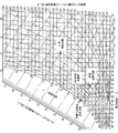
本発明にしたがえば、密閉空間57への供給空気のための所望の給送空気温度及び湿度のレベルを上で論じたASHRAE快適帯内に維持できる。これらの温度及び湿度条件から、対応する湿球温度を決定でき、図2の乾湿計図上の点3で表される所望の状態を確立できる。この湿球温度は、供給空気の(これがリターン空気だけであっても、上述したように補給空気と混合されていても)冷却及び乾燥のための目標設定点として用いられる。圧縮機28の可変容量を利用すれば、乾燥剤ホイールの処理区画54を空気が通過した後に点3の状態の達成を可能にするであろう温度に冷却コイル52を出る供給空気の温度を維持するように、冷却コイル52の容量が制御される。この温度は所望の給送空気の計算された湿球温度より若干低いであろう。すなわち、図2に示されるように、一般に65〜95°F(18.3〜35.0℃)DBTの温度範囲ないしそれより高い温度及び90〜180gr/lb(12.9〜25.7g/kg)の間の水分含有量を有するであろう供給空気(この場合は図1に示されるような周囲空気)が、95°F(35.0℃)乾球温度(‘DBT’),78.5°F(25.8℃)湿球温度(‘WBT’)及び120gr/lb(17.1g/kg)の水分含有量(図2の点1)において冷却コイル52に入る。空気がコイル52を通過すると、空気の状態は、比較的一定の湿度で点1から図2の破線に沿って飽和に達するまで移り、次いで湿度が飽和線に沿って点2まで温度とともに下がり、50〜68°F(10.0〜20.0℃)DBTの間及び水分含有量が30〜88gr/lb(4.3〜12.6g/kg)の間の飽和状態、この場合には61°F(16.1℃)DBT及び80.4gr/lb(11.5g/kg)で、空気がコイルを出る。次いで、空気は乾燥剤ホイールの処理区画54に入る。空気がホイールを通過すると、湿球線の近似経路にしたがって、空気は乾燥され、断熱加熱される。空気は、68〜81°F(20.0〜27.2℃)DBTの間、50〜65°F(10.0〜18.3℃)WBTの間、及び30〜88gr/lb(4.3〜12.6g/kg)の水分含有量の去出状態、この場合には77°F(25.0℃)DBT,61.5°F(16.4℃)WBT及び57gr/lb(8.1g/kg)の点3まで、さらに乾燥される。所望の最終空気温度を達成するため、図1の点Cにおいて冷却コイルを出る空気の温度に応じて圧縮機を動作させることは当然である。
In accordance with the present invention, the desired supply air temperature and humidity levels for the supply air to the enclosed
点2から点3までの線に沿う移行の長さはホイール55の再生条件に依存する。本発明にしたがえば、再生空気温度は湿球線に沿ってより長い経路を与えるため、すなわちさらに乾燥するために上昇させ、より短い移行を与えるため、すなわち乾燥を弱くするために低下させる。この態様において、供給空気の去出状態(点3)が目的とする設計状態に等しくなるように、ホイールの適切な乾燥を達成することもできる。
The length of the transition along the line from point 2 to
理解されるであろうように、冷却側設定点からの要求容量があれば、凝縮コイル58は、点E(図1)における状態に依存して、凝縮コイル58に入る周囲空気流に対して変動する熱量を放出する必要があろう。常態の下で、点Eにおいて入る変動熱流束は制御されていない温度の再生空気Fがホイール55に入るという結果を生じさせるであろう。本発明にしたがえば、コイル58を通る空気流量はホイール55に入る再生空気の適切な温度を達成するためにバイパスまたは排出ファン70の使用によって変えられる。これは、ホイールに入る空気の温度を検知し、ホイールに入る空気の温度を制御するために送風機56によりコイル58を通して引き入れられる空気の量を選択的に増加または減少させるようにファン70を制御することによってなされる。次いで、いかなる不要な空気量もファン70によって大気に排出される。空気流は、温度を下げるために増量され、温度を上げるために減量される。次いで、残余空気は、所望の乾燥結果を達成するに必要とされる適切な乾燥剤乾燥度を与えるため、すなわち、図7の点2から点3への移行を与えるため、乾燥剤ホイールを通して吸い込まれる。所望の再生温度を維持するに必要な空気量が乾燥剤全体を再生するに必要な空気流量をこえる場合には、コイル58を通る過剰な空気を排出することにより、増分空気流を乾燥剤ホイールにともなう圧力降下にさらさないことによってエネルギーが保存される。これは、より小さな送風機56を用い得ることも意味する。
As will be appreciated, if there is a required capacity from the cooling side set point, the condensing
本システムにより、去出空気状態、すなわちホイール55を出る空気の温度を得るに必要な最高吸引圧力で圧縮機28を動作させることが可能になる。これがなされれば、圧縮機は目的とする結果を得ることができる最小圧力比に向かって動作する。よって、サイクル能力は最大化され、エネルギー消費が低減される。
The system allows the
追加の感応性冷却を得る必要がある場合は、乾燥剤ホイールを出る空気をさらに冷却するために二次冷却コイル52'を用いることができる。このコイルには同じ圧縮機28から冷媒を供給できる。図1A及び1Bに示されるように、この追加のコイル52'は送風機50のいずれの側にも配置できる。図1Aに示される位置においては、送風機50を空気が通過することにより生じる空気温度の若干の上昇後に供給空気温度をコイル52'によって下げることが可能になる。図1Bに示される位置においては、送風機による温度上昇が問題にならない場合に、コイル52'が送風機50の上流側にある。冷却コイルはファンの吸入側においてより効率的にはたらくから、付加される送風機熱を考慮する必要がなければ、これが好ましい実施形態である。
If additional sensitive cooling needs to be obtained, a
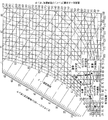
上述した制御システムに対する代替として、密閉空間に対する所望の冷却容量を与えるために装置の冷却側の容量を制御することにより、すなわち、所望の密閉空間温度を用いて圧縮機を制御し、システムの凝縮側の適宜の調節を可能にすることによって、湿球温度を計算せずに制御を達成することもできる。この場合、許容できる凝縮圧力限界範囲内で、必要な再生温度を達成し、よって必要な再生容量も達成するように、凝縮器58を通して引かれる空気の量が制御される。再生温度は、許容できる圧力限界範囲内で、流出湿度比を下げる場合は上昇させ、乾燥容量を小さくする場合は低下させる。このシステムが図3に示され、図3においては、95°F(35.0℃)DBT,78.5°F(25.8℃)WBT,120gr/lb(17.1g/kg)の点1において周囲空気が冷却コイルに入る。空気は冷却コイルを通ると、破線にしたがって飽和曲線に向かい、飽和50°F(10.0℃)及び64.6gr/lb(9.2g/kg)にある点2に移る。次いで、この空気は乾燥剤ホイールの処理区画54に入る。空気がホイールを通過すると、空気は乾燥し、湿球線の近似経路にしたがって断熱的に加熱されて、69°F(20.6℃)DBT,52°F(11.1℃)WBT,30gr/lb(4.3g/kg)の去出状態である点3に移る。上述したような予備冷却温度及び再生温度の最低化及び制御の組み合された効果により、ASHRAE快適帯内の目標去出条件が達成される。
As an alternative to the control system described above, by controlling the capacity on the cooling side of the device to provide the desired cooling capacity for the enclosed space, i.e., controlling the compressor using the desired enclosed space temperature and condensing the system Control can also be achieved without calculating the wet bulb temperature by allowing appropriate side adjustments. In this case, the amount of air drawn through the
湿球線に沿う移行の長さは再生条件に依存する。上述したように、再生温度は、線に沿うより長い経路、すなわちより強い乾燥を与える場合には上昇させ、乾燥を弱める場合には低下させる。初めに述べた代替制御システムにおいては、感応性冷却容量が増大させられて、装置による密閉空間の冷却の提供が可能になる。 The length of the transition along the wet bulb line depends on the regeneration conditions. As mentioned above, the regeneration temperature is increased to give a longer path along the line, i.e. stronger drying, and decreased to reduce drying. In the alternative control system described at the outset, the sensitive cooling capacity is increased, allowing the device to provide cooling of the enclosed space.
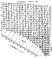
図13は図1にしたがう空気調節/除湿ユニット10の簡略な平面図を示し、各コンポーネントは図1と同じ参照数字をもつ。図13に示されるように、ユニット10は上述したダクト配管51,61の必要を排した配置で筐体100に収められている。筐体100は、内壁102によってプレナム室区画104,106に分けられる内部プレナム室100を定める直方体の箱のような構造体である。乾燥剤ホイールは、処理区画54がプレナム室104内に配置され、再生区画60がプレナム室106内にあるように、内壁102に回転可能な態様で取り付けられる。送風機70がプレナム室106の一方の側面108に配置されて、対向する側面110の開口(図示せず)を通し、コイル58を通り越して供給空気を引き入れる。この空気は圧縮機28を冷却するために圧縮機28通って流れ、壁108の開口を通して大気に放出される。
FIG. 13 shows a simplified top view of the air conditioning /
送風機50がプレナム室104内の、プレナム室104の壁114で定められる副プレナム室112内においてホイール55の処理区画の近くに配置される。送風機50は、端壁116の開口(図示せず)を通し、エバポレータコイル52を通り越し、また処理区画54を通して、供給空気を副プレナム室112に引き入れる。副プレナム室から、供給空気は、副プレナム室112にある壁110の開口(図示せず)を通して、密閉空間57に至る独立ダクト配管の中に放出される。
A
送風機56が乾燥剤ホイールの再生区画54の下流側に隣接してプレナム室106に取り付けられる。バッフルあるいはその他の隔離またはチャネル手段118がホイール55に隣接してプレナム室106内に配置され、壁108に向けて延びる分流路を形成する。上述したように、送風機56は、乾燥剤ホイールを再生するために、コイル58を出る空気の幾分かをホイールの再生区画60を通して引く。バッフル118が、ホイールを出る空気が再循環してホイールの周りに戻ることを防止する。この空気は次いで、ファン70によってプレナム室から大気に排出される空気と混合されるか、あるいは、全体または一部が、供給空気配管に独立に送られ得る。
A
この構造は、小型、ダクト配管の排除並びに凝縮器及び再生ファン/送風機の馬力(W数)の低減など、数多くの利点を有する。いかなるバックドラフト防止ルーバーの凝縮器回路への使用も排除される。 This structure has a number of advantages such as small size, elimination of duct piping and reduction of the horsepower (W number) of the condenser and regenerative fan / blower. Use of any backdraft prevention louver in the condenser circuit is eliminated.
本発明の別の実施形態が図4に示される。本実施形態において、システムは補給空気を処理し、リターン空気流からエンタルピーを回収するように構成されている。リターン空気は、収容人数能力により生じる大空間補給空気要件により新鮮空気が与えられ、透気負荷最小化のための空間与圧のための大量の空気が必要とされない用途において利用できることが多い。このタイプの設計は一般に、湿度を通常レベルより低い(湿度が低い状態であるほどエネルギー及び品質上の利益が得られるスーパーマーケット及びスケートリンクで必要とされるような)レベルに制御する必要がない、学校、劇場、アリーナ及びその他の商業スペースに用いられる。さらに、そのような広い空間は内部にかなりの熱量を有する大量の空気を用いる。 Another embodiment of the present invention is shown in FIG. In this embodiment, the system is configured to process make-up air and recover enthalpy from the return air stream. Return air is often available in applications where the large space make-up air requirement created by the capacity capacity provides fresh air and does not require a large amount of air for space pressurization to minimize air permeability load. This type of design generally does not require the humidity to be controlled to a level below normal levels (such as is required in supermarkets and skating rinks where lower humidity provides energy and quality benefits) Used for schools, theatres, arenas and other commercial spaces. Furthermore, such a large space uses a large amount of air having a considerable amount of heat inside.
図4の実施形態のシステムは、乾燥剤ホイール55及び供給空気流を密閉空間82に運ぶための送風機50が後続する、戸外環境の供給空気流Aの処理のための冷却コイル52を備える。この空気流は補給空気を構成する。エバポレータまたは冷却コイル52は複数のDX冷媒圧縮機回路に連結される。このことが2つのコイル52,52'及びそれぞれが付帯する2基の圧縮機28及び28'として図4に示される。しかし、コイル52及び圧縮機28を含む冷却回路が、独立のコイル及び圧縮機を含む、2つより多くの独立に動作可能な回路からなり得ることは当然である。
The system of the embodiment of FIG. 4 comprises a cooling
第2のすなわち再生空気流Eが空間82から引き入れられ、第2の空気流の量は第1の空気流Aの補給空気の50〜100%にほぼ等しい。第2の空気流は初めに凝縮コイル58を通過し、次いで乾燥剤ホールの再生区画を通過して、密閉空間から環境に放出される。本システムのための冷却回路は、凝縮器において空気流に放出される(すなわち移し渡される)所要の熱が、リターン空気温度とほぼ130°F(54.4℃)の最大冷却回路凝縮温度の間で、第2の空気流の熱搬送容量をこえないように、設計される。このコイル58からの冷媒は次いで、第1の(供給)空気流を冷却するために用いられる。
A second or regenerative air stream E is drawn from the
また図4に示されるように、1基より多くの補助圧縮機が供給空気流の冷却コイルに連結される。これらの補助圧縮機は補給周囲空気流を環境状態から57〜63°F(13.9〜17.2℃)まで下げるための補助冷却能力を与えるような容量をもつ。これらの補助冷却回路は、それぞれ自体の、熱を周囲に直接放出する凝縮回路を有する。このことが、それを通してファン70により引き入れられる周囲空気を処理する凝縮器52'で図4に示される。
Also, as shown in FIG. 4, more than one auxiliary compressor is connected to the cooling coil of the supply air flow. These auxiliary compressors have a capacity to provide an auxiliary cooling capacity to reduce the make-up ambient air flow from ambient conditions to 57-63 ° F. (13.9-17. 2 ° C.). Each of these auxiliary cooling circuits has its own condensation circuit that releases heat directly to the surroundings. This is illustrated in FIG. 4 with a
本実施形態において、乾燥剤ホイール55を高回転速度、すなわち10〜30rpm,及び低回転速度すなわち4〜30rphで選択的に回転させることができる集成駆動モーター装置が乾燥剤ホイールに装備される。高速モードにおいて、乾燥剤ホイールはエンタルピー交換器として作用し、再生空気流と補給空気流の間で潜熱及び顕熱を移すであろう。乾燥剤ホイールは冬季には補給空気を加熱及び加湿し、夏季には冷却及び除湿するであろう。
In this embodiment, the desiccant wheel is equipped with a centralized drive motor device that can selectively rotate the
本実施形態のシステムは異なる5つのモードで動作できる。以降で説明するように、システム性能が空間要件に適合するように圧縮機及びホイール速度の状態を変更できる。本システムは5つのモードのいずれにおいても、あるいは組合せにおいても稼働できる。主要な5つのモードは、冷却限定モード、除湿限定モード、冷却及び除湿モード、エンタルピー交換モード及び新鮮空気モードである。 The system of this embodiment can operate in five different modes. As described below, the compressor and wheel speed states can be changed so that the system performance meets the space requirements. The system can operate in any of the five modes or combinations. The five main modes are a cooling limited mode, a dehumidifying limited mode, a cooling and dehumidifying mode, an enthalpy exchange mode, and a fresh air mode.
冷却限定モードにおける本システムの動作が図5の乾湿計図に示される。本モードにおいては乾燥剤ホイール55が運転されず、空間に十分な冷却を与えるに必要な数の圧縮機だけが動作する。しかし、凝縮器コイル58がリターン空気配管にある圧縮機28'はホイールが動作していないから動作しない。本モードにおける動作は図5に示されるように空気流Aの周囲空気が95°F(35.0℃)DBT,78.5°F(25.8℃)WBT,120gr/lb(17.1g/kg)水分含有量にある点1の条件で冷却コイルバンクに入る。空気が冷却/エバポレータコイルを通過すると、空気は破線に沿って飽和曲線に移行して、飽和曲線上を、飽和65°F(18.3℃),92.8gr/lb(13.3g/kg)にある点2まで下がる。この時点で空気は冷却および除湿されているが、ホイールによる除湿が行われていないから、必ずしもASHRAE快適帯に入るとは限らない。凝縮コイル58'で吸収される熱は凝縮器及びファン70によって周囲空気流に単に放出されるだけである。
The operation of the system in the limited cooling mode is shown in the moisture meter diagram of FIG. In this mode, the
除湿限定モードにおける図4のシステムの動作が図6の乾湿計図に示される。本モードにおいては乾湿剤ホイールが低速モード(すなわち4〜30rph)で運転され、リターン空気流Eに凝縮器コイル58を提供する圧縮機28'が再生空気を加熱するように動作している。圧縮機28及びコイル58',52を含む他の冷却回路は運転されない。したがって、図6に示されるように、周囲空気Aが、95°F(35.0℃)DBT,78.5°F(25.8℃)WBT,及び120gr/lb(17.1g/kg)にある点1の状態でエバポレータコイルバンクに入る。この空気がコイル52',52を通過すると、空気は飽和線まで図上の破線に沿ってコイル52'で冷却され、飽和線上を飽和65°F(18.3℃),92.8gr/lb(13.3g/kg)にある点2まで下がる。乾燥剤ホイールが動作しているから、空気流Aはホイールで処理さる。すなわち、空気流Aは乾燥されて、湿球線の近似経路にしたがって断熱的に加熱される。空気流は乾燥剤ホイールを出て、79°F(26.1℃)DBT,66°F(18.9℃)WBT及び75gr/lb(10.7g/kg)にある点3の状態で密閉空間82に供給される。
The operation of the system of FIG. 4 in the dehumidification limited mode is shown in the moisture meter diagram of FIG. In this mode, the desiccant wheel is operated in the low speed mode (i.e., 4-30 rph) and the
本例及び一般的動作において、空間82から送風機56によって取り入れられる空気は、周囲空気の供給空気流とほぼ同じ状態である、約80°F(26.7℃)DBT及び67°F(19.4℃)WBTの状態にあるであろう。この再生空気(すなわち空間からの排出空気)は凝縮器コイル58を通され、コイルから放出される熱を受け取り、次いでホイール55を通過してホイールを再生する。これは、本動作条件において、凝縮器コイルを出る排出空気は、周囲空気が用いられる場合よりも比較的低い湿度を有するであろうから、周囲空気だけを使用するホイール再生に優る大きな利点である。すなわち、凝縮器コイルを出る排出空気はより多くの水分を吸収し、戸外空気だけで達成し得る乾燥剤能力よりも大きく乾燥剤能力を向上させるであろう。ホイールを通過した後、空気は大気に排出される。
In this example and general operation, the air taken by the
冷却及び除湿モードにおける図4のシステムの動作が図7の乾湿計図に示される。本モードにおいては、除湿限定モードにおけるように、乾燥剤ホイールが緩やかに(4〜30rphで)回転させられるが、コイル58',52及び圧縮機28を含む1つまたは複数の冷却回路がさらに、冷却限定モードにおいて行われるように、運転されることによって、さらに冷却が与えられる。この場合には、冷却モード及び除湿モードが同時に作用する。コイル58,52'及び圧縮機28'を含む第1段の冷却回路も動作し、再活性化エネルギー源を提供する。
The operation of the system of FIG. 4 in the cooling and dehumidifying mode is illustrated in the moisture meter diagram of FIG. In this mode, as in the dehumidification limited mode, the desiccant wheel is slowly rotated (at 4-30 rph), but one or more cooling
本モードで動作すると、(全てが周囲空気であるかまたは周囲空気と幾らかのリターン空気の混合気である)供給空気Aが、95°F(35.0℃)DBT,78.5°F(25.8℃)WBT,120gr/lb(17.1g/kg)にある点1において冷却コイルバンクに入る(図7)。この空気もやはり破線にしたがって飽和線に至り、飽和線上を点2まで下がって、コイル52'を出る。第2段すなわち補助段の冷却回路が動作しているから、空気の状態は飽和線上をさらに下がり続け、第2冷却段52を出た後に点3に達する。この点において、供給空気流の状態は、飽和57°F(13.9℃),69.5gr/lb(9.9g/kg)にある。この空気は次いで乾燥剤ホイール55の処理区画54に入り、そこで乾燥されて、断熱的に加熱される。空気は概ね湿球線の経路にしたがい、74°F(23.3℃)DBT,58°F(14.4℃)WBT,及び48gr/lb(6.9g/kg)にある点4でホイールを出る。
When operating in this mode, the supply air A (which is all ambient air or a mixture of ambient air and some return air) is 95 ° F (35.0 ° C) DBT, 78.5 ° F. Enter the cooling coil bank at
エンタルピー交換モードにおける図4のシステムの動作が図8の乾湿計図に示される。本モードは、戸外空気が屋内空気より高いエンタルピーにある夏季、あるいは屋内空気のエンタルピーが戸外空気のエンタルピーを上まわる冬季に一般に用いられる。 The operation of the system of FIG. 4 in the enthalpy exchange mode is shown in the moisture meter diagram of FIG. This mode is generally used in the summer when outdoor air is at a higher enthalpy than indoor air, or in the winter when the enthalpy of indoor air exceeds the enthalpy of outdoor air.
この場合、乾燥剤ホイール55は高速(10〜30rpm)で運転され、全ての冷却回路が停止される。図8に示されるように、冬季に、40°F(4.4℃)DBT,32°F(0.0℃)WBT,及び12.6gr/lb(1.8g/kg)の点1における状態を有する戸外空気が100%用いられる場合、空気の、ホイールの処理区画54の通過により、ホイールを出る空気の状態は破線に沿って点1から52.5°F(11.4℃)DBT,44.5°F(6.9℃)WBT,及び30.5gr/lb(4.4g/kg)にある点2に移される。この点から、通常の加熱器80で空気を加熱して所望の室温にすることが可能である。加熱器から引き出される排出空気は区画60に供給されて、区画60に熱及び水分を移す。
In this case, the
82.5°F(28.1℃)DBT,56°F(13.3℃)WBT及び42gr/lb(6.0g/kg)の点5にある戸外空気を100%用いる夏季においては、システムが逆の態様で動作して、空気を破線に沿って点5から、ちょうどASHRAE快適帯に入る、点6、すなわち、80°F(26.7℃)DBT,61.5°F(16.4℃)WBT,42gr/lb(6.0g/kg)に移すであろう。
In summer, the system uses 100% outdoor air at 82.5 ° F (28.1 ° C) DBT, 56 ° F (13.3 ° C) WBT and 42 gr / lb (6.0 g / kg). Operating in the opposite manner, air enters the ASHRAE comfort zone from
エンタルピー交換モードにおいて図4のシステムを周囲空気50%及びリターン空気50%で用いれば、乾燥剤ホイール処理区画54に入る空気の状態を図8上で点3から点4に移すであろう。
If the system of FIG. 4 is used with 50% ambient air and 50% return air in the enthalpy exchange mode, the state of the air entering the desiccant
図4の実施形態の動作の、最後の新鮮空気交換モードが図9の乾湿計図に示される。この場合、全ての冷却回路及び乾燥剤ホイールが停止され、新鮮空気を断えず補給するために送風機だけが運転される。この結果、システムは、熱回収、冷却または除湿を行わずに、新鮮な周囲空気を給送する。 The final fresh air exchange mode of operation of the embodiment of FIG. 4 is shown in the wet-dry meter diagram of FIG. In this case, all cooling circuits and desiccant wheels are stopped and only the blower is operated to replenish fresh air without interruption. As a result, the system delivers fresh ambient air without heat recovery, cooling or dehumidification.
本実施形態に用いられる圧縮機も、より効率の高い動作を提供するために可変型であることが好ましい。 The compressor used in the present embodiment is also preferably a variable type in order to provide more efficient operation.
本発明のまた別の実施形態が図10に示される。この実施形態のシステムは、冷却回路に2基の圧縮機20,28が用いられていることを除き、図1のシステムと同様である。2基圧縮機冷却回路を表すための図11のエバポレータクロスプロットに示されるように、圧縮機の内の1つが動作しているかまたははいずれもが動作しているかに依存して、本システムには2つの動作状態が可能である。エネルギー使用を最小限に抑えるため、システムの動作係数(COP)を高くすることにより、所望の空間湿度及び温度状態を達成できる最高吸引圧力でシステムを運転することが望ましい。可能であればいつでも2基の代りに1基の圧縮機を運転することによってもエネルギーが節約される。
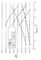
Another embodiment of the present invention is shown in FIG. The system of this embodiment is the same as the system of FIG. 1 except that two
図11は、1基及び2基の圧縮機のBTUH容量対その温度において100%の容量で動作している圧縮機の飽和吸引温度を示す、2本の右上がりの斜めの線を示す。飽和吸引温度という術語は、エバポレータ冷却コイル52を出て圧縮機に入る冷媒ガスの温度を意味する。
FIG. 11 shows two upward sloping lines showing the BTUH capacity of one and two compressors versus the saturation suction temperature of a compressor operating at 100% capacity at that temperature. The term saturated suction temperature refers to the temperature of the refrigerant gas that exits the
図11の右下がりの斜めの3本の線は、供給空気流がグラフに記されている3つの状態の内の1つにあるときの冷媒ガスの吸引温度を表し、それぞれの温度における圧縮機の対応する容量を示す。2組の斜め線が交差するところで、エバポレータ及び圧縮機は同じ状態で動作し、したがって効率が最も高い。 The three slanting lines on the lower right in FIG. 11 represent the refrigerant gas suction temperatures when the supply airflow is in one of the three states shown in the graph, and the compressor at each temperature. Indicates the corresponding capacity. Where the two sets of diagonal lines intersect, the evaporator and compressor operate in the same state and are therefore most efficient.
一般に複数基の圧縮機は(可変圧縮機も)、冷媒配管において検出される定圧点に基づくか、あるいはエバポレータ/冷却コイルを出る供給空気の温度に基づいて、動作に加わり、動作から抜けるように、運転されている。湿度制御ユニット(すなわち乾燥剤ホイール)を用いる、本発明においては、圧縮機の動作を制御するために空間湿度誤差を用いることができる。そのような‘誤差’は、室内または空間において検知される実湿度と湿度設定点(すなわち所望の湿度レベル)の間の差である。この信号は次いで、第2の圧縮機に対する吸引参加圧力点をリセットするために用いられる。湿度が下がっていないことを意味する、誤差が大きい場合には、リセット動作により吸引参加圧力がさらに低い設定に移されるであろう。他方で、誤差が小さいか、またはユニットが頻繁にオン/オフを繰り返す場合には、リセットにより吸引参加圧力が上昇するであろう。このようにして、最も安定した状態及び高められたエネルギー節約を達成できる最高吸引圧力でユニットが動作する。 In general, multiple compressors (and variable compressors) can participate in and exit from the operation based on the constant pressure point detected in the refrigerant piping or based on the temperature of the supply air exiting the evaporator / cooling coil. Is driving. In the present invention using a humidity control unit (ie desiccant wheel), the spatial humidity error can be used to control the operation of the compressor. Such 'error' is the difference between the actual humidity detected in the room or space and the humidity set point (ie, the desired humidity level). This signal is then used to reset the suction participating pressure point for the second compressor. If the error is large, meaning that the humidity has not dropped, the reset action will move the suction participation pressure to a lower setting. On the other hand, if the error is small or the unit frequently turns on and off, reset will increase the suction participation pressure. In this way, the unit operates at the highest suction pressure that can achieve the most stable state and increased energy savings.
冷却モードまたは除湿モードでの、あるいは同時に両モードでの、ユニットの運転も可能にする、本発明のさらに別の実施形態が図12に示される。 Yet another embodiment of the present invention that allows operation of the unit in cooling or dehumidifying mode or simultaneously in both modes is shown in FIG.
既存の技術は従来、冬季の間の放出圧力の過剰な低下を防止するため、冷却システムの放出圧力(すなわち、エバポレータまたは冷却コイルを出るガスの圧力)を制御していた。頭圧調節の一般的な手法の1つは凝縮器ファン速度を低減させることであり、これによりファンを運転するに必要な電力を低減するという有益な副次効果が得られる。 Existing technology has traditionally controlled the discharge pressure of the cooling system (i.e., the pressure of the gas exiting the evaporator or cooling coil) to prevent an excessive drop in the discharge pressure during the winter season. One common approach to adjusting head pressure is to reduce the condenser fan speed, which has the beneficial side effect of reducing the power required to operate the fan.
湿度制御ユニットについてもファン速度の低下は同じ効果を有し、低温で有益である。しかし、本発明に用いられる冷却用及び湿度制御ユニットは、冷却モード、除湿モード、または同時に両モードで動作する能力を有するから、工業的に容認された頭圧調節実施手段の変形が必要となる。 For the humidity control unit, the reduction in fan speed has the same effect and is beneficial at low temperatures. However, since the cooling and humidity control unit used in the present invention has the ability to operate in the cooling mode, the dehumidifying mode, or both modes at the same time, it is necessary to modify the industrially accepted head pressure adjusting means. .
高い戸外周囲温度または凝縮器の特定の設計基準に制限されなければ、圧縮機の放出圧力を80°F(26.7℃)と100°F(37.8℃)の間の飽和放出温度に等価な圧力に維持することが望ましい。本実施形態の制御システムでは、冷却モードにおいて、頭圧設定点を上記の範囲に設定することによって冷却性能が最適化されるであろう。より高い吸引圧力及びより低い放出圧力を特徴とする、より低い圧力比において最大効率が達成される。 Unless restricted to a high outdoor ambient temperature or specific design criteria for the condenser, the compressor discharge pressure should be a saturated discharge temperature between 80 ° F (26.7 ° C) and 100 ° F (37.8 ° C). It is desirable to maintain an equivalent pressure. In the control system of the present embodiment, the cooling performance will be optimized by setting the head pressure set point in the above range in the cooling mode. Maximum efficiency is achieved at lower pressure ratios, characterized by higher suction pressure and lower discharge pressure.
他方で、乾燥剤ホイール湿度制御ユニットは供給空気の流入時相対湿度と再生空気の相対湿度の間に十分な差をつくることに依存する。この差は、乾燥剤ホイールにおける水分移行の推進力である。冷却システムを可能な最低圧力比にかけて運転することも有益である。これは、より高い吸入圧力及びより低い凝縮圧力が用いられるべきであることを意味する。本発明のシステムは、冷却システムまたは乾燥剤システムのいずれかを優先させることなく、全ユニットの性能のバランスをとる。 On the other hand, the desiccant wheel humidity control unit relies on making a sufficient difference between the relative humidity of the supply air inflow and the relative humidity of the regeneration air. This difference is the driving force for moisture transfer in the desiccant wheel. It is also beneficial to operate the cooling system at the lowest possible pressure ratio. This means that higher suction pressures and lower condensation pressures should be used. The system of the present invention balances the performance of all units without prioritizing either the cooling system or the desiccant system.
これを達成するため、湿度センサ90が、加熱凝縮器コイル58の後で、再生空気流内に配置される。例示的な目標RH(相対湿度)値は10から30%RHの範囲にあるであろう。冷却コイル52を出る冷却された空気の飽和(乾湿計図の点2)が達成されているとすれば、ホイールに入る特定の検知されるRHを達成するために、空間57の空間湿度センサが頭圧をリセットするであろう。リセットは頭圧をあらかじめ定められた条件範囲内に保つように制限されるであろう。例えば、R−22冷媒を用いる場合、頭圧の限界範囲は168psig(大気圧+1.16×10⁶Pa)(90°F(32.2℃))から360psig(大気圧+2.48×10⁶Pa)(145°F(62.8℃))であろう。これらは既知のスクロール圧縮機に対して一般に許容される動作条件である。これにより、80°F(26.7℃)から140°F(60.0℃)の範囲の、凝縮器を出る空気すなわちホイールに入る空気の温度が達成され、冷却システムにおける性能の付随損失をともなう凝縮器頭圧の引上げが回避される。したがって圧縮機は最低頭圧で稼働し、それでも目標の相対湿度が得られるであろう。利益は、260psig(大気圧+1.79×106Pa)の頭圧により得られる45°F(7.2℃)の去出空気温度がより低い圧力で目標のRH%に達し、したがって圧縮機の入力電力が下がり、同時に冷却容量が高くなるであろう。
To accomplish this, a
同じ結果が、再活性化流出空気の微分または弾性あるいは再活性化流入空気温度に対する温度差を利用することによる別の方法で達成されるであろう。例えば、乾燥剤ホイールが未だに湿気ている場合には、ホイールはおそらくより低い流出空気温度を有するであろう。逆に、完全に最活性化されている、すなわち乾燥している場合には、流出空気温度が上昇し始めるであろう。ホイールの両側での空気の温度は通常の温度センサ92で検出でき、連続的にモニタできるであろう。再活性化流入空気温度の上昇がほぼ同様の流出空気温度の上昇をもたらす場合、これは、エネルギーがホイールから水分を移すために用いられておらず、したがって圧縮の適切な制御によって頭圧を低下させるべきであることを示す。
The same result would be achieved in another way by utilizing the differential or elasticity of the reactivated effluent air or the temperature difference with respect to the reactivated inflow air temperature. For example, if the desiccant wheel is still wet, the wheel will probably have a lower effluent air temperature. Conversely, when fully activated, i.e. dry, the effluent air temperature will begin to rise. The temperature of the air on both sides of the wheel can be detected with a
あるいは、ホイールを介して目標の20°F(11.1℃)の温度差を維持するように制御を設定することができる。
Alternatively, control can be set to maintain a
本システムは、再活性化温度を低下させ、したがって頭圧を低下させ、冷却性能が改善されるように、再活性化エネルギーを負荷に整合させることにより、失われるエネルギーを削減する。 The system reduces the energy lost by matching the reactivation energy to the load so that the reactivation temperature is lowered, thus reducing the head pressure and improving the cooling performance.
本発明の例示的実施形態を添付図面を参照して本明細書で説明したが、本発明がそれらの厳密な実施形態に限定されず、本発明の範囲または精神を逸脱することなく当業者によって様々な変更または改変がこれらの実施形態に実施され得ることは当然である。 While exemplary embodiments of the present invention have been described herein with reference to the accompanying drawings, the present invention is not limited to these exact embodiments and can be made by those skilled in the art without departing from the scope or spirit of the invention. It will be appreciated that various changes or modifications may be made to these embodiments.
10 空気調節/除湿システム
28 圧縮機
50,56 送風機
52 エバポレータコイル
54 処理区画
55 乾燥剤ホイール
58 凝縮器コイル
60 再生区画
70 ファン
100 筐体
102 内壁
104,106 プレナム室
112 副プレナム室
118 バッフル
10 Air Conditioning /
Claims (19)
可変圧縮器を備える冷却システムを用いて供給空気流を前記空気の温度を下げるために前記空気を冷却コイルを介してを通過させることにより冷却し、前記そのようにして冷却された供給空気流に、前記空気流の温度を上昇させるともに前記空気流の水分含有量を低減させる条件の下で、回転中の乾燥剤ホイールの一区画を通過させ次いで前記そのようにして処理された空気を前記密閉空間に給送する工程、
前記冷却システムの凝縮コイルを用いて再生空気流を加熱することにより前記乾燥剤ホイールを再生し、前記ホイール内の乾燥剤を再生するために、前記加熱された再生空気流に前記回転中の乾燥剤ホイールの別の区画を通過させる工程、
前記供給空気流、前記再生空気流及び/または前記冷却システムの少なくとも1つの状態を検知する工程、及び
前記検出された状態に応じて前記圧縮機の出力を制御する工程、
を有してなることを特徴とする方法。 In a method of adjusting air for an enclosed space,
A cooling system comprising a variable compressor is used to cool the supply air stream by passing the air through a cooling coil to reduce the temperature of the air and into the supply air stream thus cooled. Under the conditions of increasing the temperature of the air stream and reducing the water content of the air stream, the sealed desiccated air is then passed through a section of the rotating desiccant wheel. The process of feeding into space,
Regenerating the desiccant wheel by heating the regenerative air stream using a condensing coil of the cooling system, and rotating the drying to the heated regenerated air stream to regenerate the desiccant in the wheel. Passing through another section of the agent wheel,
Detecting at least one state of the supply air flow, the regeneration air flow and / or the cooling system; and controlling an output of the compressor in accordance with the detected state;
A method comprising the steps of:
65°F(18.3℃)〜95°F(35.0℃)の範囲の温度ないしさらに高い温度及び90〜180gr/lb(12.9〜25.7g/kg)の間の水分含有量を有する供給空気流を前記供給空気流の前記水分含有量及び温度を第1のあらかじめ定められた飽和水分含有量レベル及び飽和温度範囲まで下げるために冷却システムの冷却コイルを用いて冷却し、前記そのようにして冷却及び乾燥された周囲供給空気流に、前記冷却及び乾燥された空気流の温度を約68〜81°F(20.0〜27.2℃)の第2のあらかじめ定められた温度範囲まで上げ、前記冷却及び乾燥された空気の水分含有量をさらに30〜80gr/lb(4.3〜11.4g/kg)の間のあらかじめ定められた湿度レベルまで低減する条件の下で、回転中の乾燥剤ホイールの一区画を通過させる工程、及び、
次いで、前記そのようにして処理された空気を前記密閉空間に給送する工程、
再生空気流を前記再生空気流の温度を105°F(40.6℃)〜135°F(57.2℃)のあらかじめ定められた範囲の温度まで上げるために前記冷却システムの凝縮コイルを用いて加熱することにより前記乾燥ホイールを再生し次いで前記加熱された再生空気流に、前記ホイール内の乾燥剤を再生するために前記回転中の乾燥剤ホイールの別の区画を通過させる工程、
前記供給空気流、前記再生空気流及び/または前記冷却システムの少なくとも1つの状態を検知する工程、及び
前記検知された状態に応じて圧縮機の出力を制御する工程、
を有してなることを特徴とする方法。 In a method of adjusting air to supply an enclosed space,
Temperatures ranging from 65 ° F. (18.3 ° C.) to 95 ° F. (35.0 ° C.) or higher and moisture content between 90-180 gr / lb (12.9-25.7 g / kg) Cooling the supply air stream with a cooling coil of a cooling system to reduce the moisture content and temperature of the supply air stream to a first predetermined saturated moisture content level and saturation temperature range, and The cooled and dried ambient supply air stream has a second predetermined temperature of about 68 to 81 ° F. (20.0 to 27.2 ° C.). Under conditions that raise the temperature range and reduce the moisture content of the cooled and dried air to a predetermined humidity level of between 30-80 gr / lb (4.3-11.4 g / kg) Pass through a section of the rotating desiccant wheel Process and
Next, feeding the air thus treated to the sealed space;
Using the condensing coil of the cooling system to raise the temperature of the regeneration air stream to a temperature in a predetermined range of 105 ° F. (40.6 ° C.) to 135 ° F. (57.2 ° C.) Regenerating the drying wheel by heating and then passing the heated regeneration air stream through another section of the rotating desiccant wheel to regenerate the desiccant in the wheel;
Detecting at least one state of the supply air flow, the regenerative air flow and / or the cooling system; and controlling an output of a compressor according to the detected state;
A method comprising the steps of:
壁よって第1及び第2の独立プレナム室に分割されている密閉筐体、
前記筐体内の冷却回路であって、
第1のプレナム室内のエバポレータコイル、及び
第2のプレナム室内の、直列に配置された、凝縮器コイル、少なくとも1つの冷媒圧縮機及び、前記筐体の外部から前記第2のプレナム室を通して前記凝縮器コイルを介して供給空気を引き入れ、前記供給空気を前記筐体の外部に放出するように配置された、凝縮器ファン
を有する冷却回路、
前記筐体内の除湿システムであって、
乾燥剤ホイールであって、前記壁を垂直に横切る平面で回転させるために前記筐体に回転可能な態様で取り付けられ、よって、処理区画として機能する前記ホイールの第1の区画が前記第1のプレナム室に配置され、再生区画として機能する前記ホイールの第2の区画が第2のプレナム室に配置され、前記第2のプレナム室内の前記乾燥剤ホイール区画は前記凝縮器コイルを介して流れる前記空気の下流側に配置される、乾燥剤ホイール、
前記ホイールの一方の側に隣接して配置された前記第1のプレナム室内の供給/プロセス空気ファン、
前記第1のプレナム室を分割して副プレナム室を形成するための、前記ホイールの前記一方の側の近くから延び、よって前記供給/プロセス空気ファンが供給/プロセス空気流を前記第1のプレナム室に引き入れ、前記ホイールの前記処理区画を通して前記副プレナム室に引き入れて、前記そのようにして冷却及び除湿された空気を密閉空間に放出する、前記第1のプレナム室内の副分割壁、
前記乾燥剤ホイールの下流側に隣接する前記第2のプレナム室内の再生ファン、及び
前記ホイールを再生するために前記再生ファンが前記凝縮器コイルを出る空気を前記ホイールを通して引くときに、前記ホイールを出る空気が前記凝縮器コイルまたは前記ホイールの流入側に向かって流れ戻ることを防止するために、前記乾燥剤ホイールの下流側で、前記乾燥剤ホイールから前記筐体の側壁に向けて延びる、前記第2のプレナム室内のバッフル手段、
を有する除湿システム、
を備えることを特徴とする空気調節及び除湿システム。 In air conditioning and dehumidification systems,
A hermetically sealed housing divided into first and second independent plenum chambers by a wall;
A cooling circuit in the housing,
The evaporator coil in the first plenum chamber, and the condenser coil, at least one refrigerant compressor, and the condensation arranged in series in the second plenum chamber from the outside of the housing through the second plenum chamber. A cooling circuit having a condenser fan arranged to draw in supply air through a condenser coil and to release the supply air to the outside of the housing;
A dehumidification system in the housing,
A desiccant wheel, mounted in a rotatable manner to the housing for rotation in a plane perpendicular to the wall, so that the first compartment of the wheel functioning as a treatment compartment is the first compartment A second compartment of the wheel disposed in a plenum chamber and functioning as a regeneration compartment is disposed in a second plenum chamber, and the desiccant wheel compartment in the second plenum chamber flows through the condenser coil. A desiccant wheel, located downstream of the air,
A supply / process air fan in the first plenum chamber disposed adjacent to one side of the wheel;
Extending from near the one side of the wheel to divide the first plenum chamber to form a secondary plenum chamber, so that the supply / process air fan directs the supply / process air flow to the first plenum. A sub-partition wall in the first plenum chamber that is drawn into a chamber and drawn into the sub-plenum chamber through the processing section of the wheel to release the air thus cooled and dehumidified into a sealed space;
A regeneration fan in the second plenum chamber adjacent downstream of the desiccant wheel; and when the regeneration fan draws air exiting the condenser coil through the wheel to regenerate the wheel. Extending downstream from the desiccant wheel toward the sidewall of the housing on the downstream side of the desiccant wheel to prevent the exiting air from flowing back toward the condenser coil or the inflow side of the wheel, Baffle means in the second plenum chamber;
A dehumidification system,
An air conditioning and dehumidification system comprising:
乾燥剤ホイールベース除湿システム、及び
少なくとも1つの冷却回路、
を備え、
前記乾燥剤ホイール除湿システムが、
処理区画及び再生区画を有する乾燥剤ホイール、
前記空間から前記ホイールの前記再生区画を通して空気を引くための送風機、
を有し、
前記冷却回路が、
前記密閉空間から前記再生区画に流れる再生空気の経路において前記密閉空間と前記ホイールの前記再生区画の間に配置された凝縮器コイル、
エバポレータコイル、
前記エバポレータコイルを介して、前記乾燥剤ホイールの前記処理区画を通し、前記密閉区間に供給空気を引き入れるための送風機手段、及び
前記凝縮器コイルと前記エバポレータコイルの間で回路内の冷媒を移動させるための圧縮機、
を有する第1の冷却回路、及び
凝縮器コイル、
前記凝縮器コイルを介して周囲空気を引き入れ、前記引き入れられた周囲空気を大気に排出するための送風機手段、
前記乾燥剤ホイールの上流側で前記第1の再生システム内の前記供給空気流内に配置されたエバポレータコイル、及び
付帯するコイル間で冷媒を移動させるための圧縮機、
を有する第2の冷却回路、
を有し、よって、
前記第1の冷却回路だけの動作が冷却だけを生じさせ、
前記乾燥剤ホイールベースシステム及び前記第1の冷却回路だけの動作が除湿だけを生じさせ、
前記乾燥剤ホイールベースシステム並びに前記第1及び第2の冷却回路の動作が冷却及び除湿をともに生じさせ、
前記乾燥剤ホイールベースシステムだけの動作が前記再生空気流と前記供給空気流の間のエンタルピー交換を生じさせ、
前記乾燥剤ホイールベースシステムも前記冷却回路も動作しない、前記送風機だけの動作が新鮮空気の循環だけを生じさせる、
ことを特徴とする装置。 In an apparatus for selectively heating, cooling and dehumidifying air in an enclosed space,
A desiccant wheel-based dehumidification system, and at least one cooling circuit;
With
The desiccant wheel dehumidification system comprises:
A desiccant wheel having a treatment compartment and a regeneration compartment;
A blower for drawing air from the space through the regeneration section of the wheel;
Have
The cooling circuit is
A condenser coil disposed between the enclosed space and the regeneration section of the wheel in a path of regeneration air flowing from the enclosed space to the regeneration section;
Evaporator coil,
Blower means for drawing supply air through the processing section of the desiccant wheel through the evaporator coil and drawing the supply air into the sealed section, and moving refrigerant in the circuit between the condenser coil and the evaporator coil Compressor for,
A first cooling circuit having a condenser coil,
Blower means for drawing ambient air through the condenser coil and discharging the drawn ambient air to the atmosphere;
An evaporator coil disposed in the supply air flow in the first regeneration system upstream of the desiccant wheel, and a compressor for moving refrigerant between the accompanying coils;
A second cooling circuit having
And thus
Only the operation of the first cooling circuit results in cooling only;
Operation of only the desiccant wheelbase system and the first cooling circuit results in only dehumidification;
Operation of the desiccant wheelbase system and the first and second cooling circuits cause both cooling and dehumidification;
Operation of the desiccant wheelbase system alone causes an enthalpy exchange between the regeneration air stream and the supply air stream;
Neither the desiccant wheelbase system nor the cooling circuit operates, the operation of the blower alone causes only fresh air circulation,
A device characterized by that.
乾燥剤ホイールベース除湿システム、及び
少なくとも2つの冷却回路、
を備え、
前記乾燥剤ホイール除湿システムが、
処理区画及び再生区画を有する乾燥剤ホイール、
前記空間から前記ホイールの前記再生区画を通して空気を引くための送風機、
を有し、
前記冷却回路が、
前記密閉空間から前記再生区画に流れる再生空気の経路において前記密閉空間と前記ホイールの前記再生区画の間に配置された凝縮器コイル、
エバポレータコイル、
前記エバポレータコイルを介して、前記乾燥剤ホイールの前記処理区画を通して、前記密閉区間に供給空気を引き入れるための送風機手段、及び
前記凝縮器コイルと前記エバポレータコイルの間で回路内の冷媒を移動させるための圧縮機、
を有する第1の冷却回路、及び
凝縮器コイル、
前記凝縮器コイルを介して周囲空気を引き入れ、前記引き入れられた周囲空気を大気に排出するための送風機手段、
前記乾燥剤ホイールの上流側で前記第1の再生システム内の前記供給空気流内に配置されたエバポレータコイル、及び
付帯するコイル間で冷媒を移動させるための圧縮機、
を有する少なくとも第2の冷却回路、
を有し、よって、
前記第1の冷却回路だけの動作が冷却だけを生じさせ、
前記乾燥剤ホイールベースシステム及び前記第1の冷却回路だけの動作が除湿だけを生じさせ、
前記乾燥剤ホイールベースシステム並びに前記第1及び第2の冷却回路の動作が冷却及び除湿をともに生じさせ、
前記乾燥剤ホイールベースシステムだけの動作が前記再生空気流と前記供給空気流の間のエンタルピー交換を生じさせ、
前記乾燥剤ホイールベースシステムも前記冷却回路も動作しない、前記送風機だけの動作が新鮮空気の循環だけを生じさせる、
ことを特徴とする装置。 In an apparatus for selectively heating, cooling and dehumidifying air in an enclosed space,
A desiccant wheel-based dehumidification system, and at least two cooling circuits;
With
The desiccant wheel dehumidification system comprises:
A desiccant wheel having a treatment compartment and a regeneration compartment;
A blower for drawing air from the space through the regeneration section of the wheel;
Have
The cooling circuit is
A condenser coil disposed between the enclosed space and the regeneration section of the wheel in a path of regeneration air flowing from the enclosed space to the regeneration section;
Evaporator coil,
Blower means for drawing supply air into the sealed section through the processing section of the desiccant wheel via the evaporator coil, and for moving refrigerant in the circuit between the condenser coil and the evaporator coil Compressor,
A first cooling circuit having a condenser coil,
Blower means for drawing ambient air through the condenser coil and discharging the drawn ambient air to the atmosphere;
An evaporator coil disposed in the supply air flow in the first regeneration system upstream of the desiccant wheel, and a compressor for moving refrigerant between the accompanying coils;
At least a second cooling circuit,
And thus
Only the operation of the first cooling circuit results in cooling only;
Operation of only the desiccant wheelbase system and the first cooling circuit results in only dehumidification;
Operation of the desiccant wheelbase system and the first and second cooling circuits cause both cooling and dehumidification;
Operation of the desiccant wheelbase system alone causes an enthalpy exchange between the regeneration air stream and the supply air stream;
Neither the desiccant wheelbase system nor the cooling circuit operates, the operation of the blower alone causes only fresh air circulation,
A device characterized by that.
Applications Claiming Priority (2)
| Application Number | Priority Date | Filing Date | Title |
|---|---|---|---|
| US10/316,952 US6711907B2 (en) | 2001-02-28 | 2002-12-12 | Desiccant refrigerant dehumidifier systems |
| PCT/US2003/018090 WO2004055443A1 (en) | 2002-12-12 | 2003-06-09 | Desiccant refrigerant dehumidifier systems |
Publications (2)
| Publication Number | Publication Date |
|---|---|
| JP2006509989A true JP2006509989A (en) | 2006-03-23 |
| JP2006509989A5 JP2006509989A5 (en) | 2006-07-27 |
Family
ID=32592868
Family Applications (1)
| Application Number | Title | Priority Date | Filing Date |
|---|---|---|---|
| JP2004560269A Pending JP2006509989A (en) | 2002-12-12 | 2003-06-09 | Desiccant refrigerant dehumidifier system |
Country Status (12)
| Country | Link |
|---|---|
| US (3) | US6711907B2 (en) |
| EP (1) | EP1581773A1 (en) |
| JP (1) | JP2006509989A (en) |
| KR (1) | KR100766054B1 (en) |
| CN (1) | CN100350192C (en) |
| AU (1) | AU2003251422C1 (en) |
| BR (1) | BR0316773B1 (en) |
| HK (1) | HK1085263A1 (en) |
| IL (1) | IL169058A (en) |
| MX (1) | MXPA05006118A (en) |
| NZ (1) | NZ540581A (en) |
| WO (1) | WO2004055443A1 (en) |
Cited By (3)
| Publication number | Priority date | Publication date | Assignee | Title |
|---|---|---|---|---|
| JP2007187386A (en) * | 2006-01-13 | 2007-07-26 | Hitachi Plant Technologies Ltd | Dehumidification air conditioning system |
| JP2010529398A (en) * | 2007-05-30 | 2010-08-26 | マンターズ コーポレイション | Humidity control system using desiccant equipment |
| JP2014206376A (en) * | 2014-08-04 | 2014-10-30 | 高砂熱学工業株式会社 | Outdoor air treatment device using desiccant rotor |
Families Citing this family (109)
| Publication number | Priority date | Publication date | Assignee | Title |
|---|---|---|---|---|
| US6505475B1 (en) | 1999-08-20 | 2003-01-14 | Hudson Technologies Inc. | Method and apparatus for measuring and improving efficiency in refrigeration systems |
| JP2003097825A (en) * | 2001-07-18 | 2003-04-03 | Daikin Ind Ltd | Air conditioner |
| JP3709815B2 (en) * | 2001-07-18 | 2005-10-26 | ダイキン工業株式会社 | Air conditioner |
| JP3696224B2 (en) * | 2003-03-19 | 2005-09-14 | 株式会社グリーンセイジュ | Drying system |
| US7066091B2 (en) * | 2003-06-16 | 2006-06-27 | R.R. Donnelley & Sons Company | Methods and apparatus for controlling impurity levels in an enclosed printing press environment |
| KR100598220B1 (en) * | 2004-05-21 | 2006-07-07 | 엘지전자 주식회사 | an air conditioner's outdoor apparatus |
| US7260945B2 (en) * | 2004-05-22 | 2007-08-28 | Allanco Technologies, Inc. | Desiccant-assisted air conditioning system and process |
| EP1774230A2 (en) * | 2004-06-08 | 2007-04-18 | Nanopore, Inc. | Sorption cooling systems, their use in automotive cooling applications and methods relating to the same |
| JP4775623B2 (en) * | 2004-10-26 | 2011-09-21 | 株式会社日立プラントテクノロジー | Dehumidification system |
| US7155318B2 (en) * | 2004-11-05 | 2006-12-26 | Hewlett-Packard Development Company, Lp. | Air conditioning unit control to reduce moisture varying operations |
| US7226497B2 (en) * | 2004-11-30 | 2007-06-05 | Ranco Incorporated Of Delaware | Fanless building ventilator |
| JP4052319B2 (en) * | 2005-05-24 | 2008-02-27 | ダイキン工業株式会社 | Air conditioning system |
| JP3864982B2 (en) * | 2005-05-30 | 2007-01-10 | ダイキン工業株式会社 | Air conditioning system |
| WO2008018071A2 (en) * | 2006-08-08 | 2008-02-14 | Ewa Tech Ltd | Method and apparatus for extracting water from atmospheric air and utilizing the same |
| US9216197B2 (en) * | 2006-09-11 | 2015-12-22 | Biomas Ltd. | Topical formulations of tellurium-containing compounds |
| DK200600246Y6 (en) * | 2006-09-19 | 2007-10-12 | P S E Aps | Mobile pipe drying plant |
| US7874499B2 (en) * | 2006-11-22 | 2011-01-25 | Store-N-Stuff Llc | System and method to control sensible and latent heat in a storage unit |
| EP2097694A4 (en) * | 2006-12-29 | 2012-02-22 | Carrier Corp | System and method for controlling temperature and humidity of a controlled space |
| WO2008118565A2 (en) * | 2007-03-06 | 2008-10-02 | Steris Inc. | Shelf assembly |
| KR100775075B1 (en) * | 2007-08-13 | 2007-11-08 | (주)에이티이엔지 | Desiccant dehumidifier |
| DE102007038354A1 (en) * | 2007-08-14 | 2009-02-19 | BSH Bosch und Siemens Hausgeräte GmbH | Refrigeration device with moisture separation and operating method for it |
| CA2706490A1 (en) * | 2007-12-03 | 2009-07-23 | Gerald Landry | Thermodynamic closed loop desiccant rotor system and process |
| US7654101B2 (en) * | 2007-12-07 | 2010-02-02 | Shapiro Ian M | Split-air stream air conditioning with desiccant dehumidification |
| JP5248629B2 (en) * | 2008-01-25 | 2013-07-31 | アライアンス フォー サステイナブル エナジー リミテッド ライアビリティ カンパニー | Indirect evaporative cooler using liquid desiccant contained in membrane for dehumidification |
| CA2707793C (en) * | 2008-02-14 | 2016-03-29 | Munters Corporation | Energy recovery enhanced condenser reactivated desiccant refrigerant dehumidifier |
| US8051670B2 (en) * | 2008-05-09 | 2011-11-08 | Thermo King Corporation | HVAC management system for a vehicle |
| US20090277195A1 (en) * | 2008-05-09 | 2009-11-12 | Thermo King Corporation | Refrigeration system including a desiccant |
| US8602087B2 (en) * | 2008-11-19 | 2013-12-10 | Tai-Her Yang | Double flow-circuit heat exchange device for periodic positive and reverse directional pumping |
| JP5405801B2 (en) * | 2008-11-07 | 2014-02-05 | ヤンマー株式会社 | Desiccant air conditioner |
| CN102317699B (en) * | 2009-02-20 | 2014-11-12 | 三菱电机株式会社 | Use-side unit and air conditioner |
| DE102009010151B4 (en) * | 2009-02-23 | 2010-12-16 | Airbus Deutschland Gmbh | An aircraft air conditioning system with a dehumidifying device and method for operating such an aircraft air conditioning system |
| US20100242507A1 (en) * | 2009-03-24 | 2010-09-30 | Milton Meckler | Dynamic outside air management system and method |
| US8328904B2 (en) | 2009-05-04 | 2012-12-11 | Bry-Air, Inc. | Method and system for control of desiccant dehumidifier |
| KR101408990B1 (en) * | 2009-05-04 | 2014-06-18 | 브리-에어 (아시아) 프라이빗 리미티드 | Desiccant unit control system and method |
| US20100281893A1 (en) * | 2009-05-11 | 2010-11-11 | Stulz Air Technology Systems, Inc. | Desiccant dehumidifier utilizing hot water for reactivation, and related method |
| KR100928843B1 (en) * | 2009-07-08 | 2009-11-30 | (주)에이티이엔지 | Hybrid drying system and thereof control method |
| US9038409B2 (en) * | 2009-09-21 | 2015-05-26 | Korea Research Institute Of Chemical Technology | Apparatus for treating air by using porous organic-inorganic hybrid materials as an absorbent |
| JP2011085270A (en) * | 2009-10-13 | 2011-04-28 | Yamatake Corp | Desiccant air conditioning system and method of operating the same |
| ES2752069T3 (en) * | 2010-05-25 | 2020-04-02 | 7Ac Tech Inc | Methods and systems using liquid desiccants for air conditioning and other processes |
| US8943848B2 (en) * | 2010-06-16 | 2015-02-03 | Reznor Llc | Integrated ventilation unit |
| CN103069246B (en) | 2010-06-24 | 2016-02-03 | 北狄空气应对加拿大公司 | Liquid-to-air membrane energy exchanger |
| JP2013543106A (en) * | 2010-11-22 | 2013-11-28 | マンターズ コーポレイション | Desiccant dehumidification system with enhanced cooling capacity |
| CN103229006B (en) * | 2010-12-22 | 2015-11-25 | 三菱电机株式会社 | Supplying hot water air-conditioning set composite |
| US8915092B2 (en) * | 2011-01-19 | 2014-12-23 | Venmar Ces, Inc. | Heat pump system having a pre-processing module |
| US9810439B2 (en) | 2011-09-02 | 2017-11-07 | Nortek Air Solutions Canada, Inc. | Energy exchange system for conditioning air in an enclosed structure |
| BR112014005685B1 (en) | 2011-09-12 | 2021-05-11 | Bry Air [Asia] Pvt. Ltd | Apparatus and Method for Controlling a Rotary Solid Desiccant Dehumidifier |
| US8828128B1 (en) | 2011-12-23 | 2014-09-09 | Novelaire Technologies, L.L.C. | Desiccant dehumidification system and method |
| US9574782B2 (en) | 2012-01-20 | 2017-02-21 | Innovent Air Handling Equipment, LLC | Dehumidification system |
| US9976822B2 (en) | 2012-03-22 | 2018-05-22 | Nortek Air Solutions Canada, Inc. | System and method for conditioning air in an enclosed structure |
| US9308490B2 (en) | 2012-06-11 | 2016-04-12 | 7Ac Technologies, Inc. | Methods and systems for turbulent, corrosion resistant heat exchangers |
| CH706736A1 (en) * | 2012-07-09 | 2014-01-15 | Belimo Holding Ag | Process for operating a heat exchanger and HVAC system for performing the process. |
| US9816760B2 (en) | 2012-08-24 | 2017-11-14 | Nortek Air Solutions Canada, Inc. | Liquid panel assembly |
| US9719423B2 (en) | 2012-09-04 | 2017-08-01 | General Electric Company | Inlet air chilling system with humidity control and energy recovery |
| JP6138457B2 (en) * | 2012-11-13 | 2017-05-31 | 株式会社西部技研 | Drying room for glove box |
| US9506697B2 (en) | 2012-12-04 | 2016-11-29 | 7Ac Technologies, Inc. | Methods and systems for cooling buildings with large heat loads using desiccant chillers |
| ITMI20122084A1 (en) * | 2012-12-06 | 2014-06-07 | Climaveneta S P A | AIR HANDLING UNIT ENTRY INTO AN ENVIRONMENT |
| US20140190037A1 (en) * | 2013-01-09 | 2014-07-10 | Venmar Ces, Inc. | System and method for providing conditioned air to an enclosed structure |
| KR20150122167A (en) | 2013-03-01 | 2015-10-30 | 7에이씨 테크놀로지스, 아이엔씨. | Desiccant air conditioning methods and systems |
| US10006649B2 (en) * | 2013-03-05 | 2018-06-26 | Mitsubishi Electric Corporation | Air-conditioning system |
| US9109808B2 (en) | 2013-03-13 | 2015-08-18 | Venmar Ces, Inc. | Variable desiccant control energy exchange system and method |
| US10352628B2 (en) | 2013-03-14 | 2019-07-16 | Nortek Air Solutions Canada, Inc. | Membrane-integrated energy exchange assembly |
| EP2972009B1 (en) | 2013-03-14 | 2019-09-18 | 7AC Technologies, Inc. | Split liquid desiccant air conditioning system |
| KR20150119345A (en) | 2013-03-14 | 2015-10-23 | 7에이씨 테크놀로지스, 아이엔씨. | Methods and systems for liquid desiccant air conditioning system retrofit |
| US10584884B2 (en) | 2013-03-15 | 2020-03-10 | Nortek Air Solutions Canada, Inc. | Control system and method for a liquid desiccant air delivery system |
| US11408681B2 (en) | 2013-03-15 | 2022-08-09 | Nortek Air Solations Canada, Iac. | Evaporative cooling system with liquid-to-air membrane energy exchanger |
| EP3667191A1 (en) | 2013-06-12 | 2020-06-17 | 7AC Technologies, Inc. | Liquid desiccant air conditioning system |
| US9638434B2 (en) * | 2013-09-18 | 2017-05-02 | Alaska Structures, Inc. | Environment control system and devices |
| WO2015125251A1 (en) * | 2014-02-20 | 2015-08-27 | 三菱電機株式会社 | Air-conditioning device and method for controlling air-conditioning device |
| CN110594883B (en) | 2014-03-20 | 2022-06-14 | 艾默生环境优化技术有限公司 | Combined heat exchanger and water injection system |
| WO2015192249A1 (en) | 2014-06-20 | 2015-12-23 | Nortek Air Solutions Canada, Inc. | Systems and methods for managing conditions in enclosed space |
| DK3183051T3 (en) | 2014-08-19 | 2020-06-02 | Nortek Air Solutions Canada Inc | LIQUID-TO-LUFTMEMBRANENERGIVEKSLERE |
| WO2016031139A1 (en) * | 2014-08-29 | 2016-03-03 | パナソニックIpマネジメント株式会社 | Dehumidifying device |
| JP6718871B2 (en) | 2014-11-21 | 2020-07-08 | 7エーシー テクノロジーズ,インコーポレイテッド | Liquid desiccant air conditioning system |
| KR101679574B1 (en) * | 2015-02-09 | 2016-11-25 | 엘지전자 주식회사 | Air conditioner |
| SG10201913923WA (en) | 2015-05-15 | 2020-03-30 | Nortek Air Solutions Canada Inc | Using liquid to air membrane energy exchanger for liquid cooling |
| US11092349B2 (en) | 2015-05-15 | 2021-08-17 | Nortek Air Solutions Canada, Inc. | Systems and methods for providing cooling to a heat load |
| US10935275B2 (en) * | 2015-05-29 | 2021-03-02 | Carrier Corporation | HVAC system thermal recovery |
| CA2990765A1 (en) | 2015-06-26 | 2016-12-29 | Nortek Air Solutions Canada, Inc. | Three-fluid liquid to air membrane energy exchanger |
| KR101746154B1 (en) * | 2015-07-15 | 2017-06-13 | 한국과학기술연구원 | Air conditioning system |
| EP3400407A4 (en) | 2016-01-08 | 2019-08-07 | Nortek Air Solutions Canada, Inc. | Integrated make-up air system in 100% air recirculation system |
| EP3426984A4 (en) | 2016-03-08 | 2019-11-20 | Nortek Air Solutions Canada, Inc. | Systems and methods for providing cooling to a heat load |
| CN105671216A (en) * | 2016-03-29 | 2016-06-15 | 海宁市富升裘革有限公司 | Low-temperature dehumidifying and drying system for leather |
| US10907845B2 (en) | 2016-04-13 | 2021-02-02 | Trane International Inc. | Multi-functional heat pump apparatus |
| US10274228B2 (en) | 2016-04-28 | 2019-04-30 | Trane International Inc. | Packaged HVAC unit with secondary system capability |
| US10350536B2 (en) | 2016-11-09 | 2019-07-16 | Climate By Design International, Inc. | Reverse flow dehumidifier and methods of operating the same |
| US10653042B2 (en) | 2016-11-11 | 2020-05-12 | Stulz Air Technology Systems, Inc. | Dual mass cooling precision system |
| WO2018191806A1 (en) | 2017-04-18 | 2018-10-25 | Nortek Air Solutions Canada, Inc. | Desiccant enhanced evaporative cooling systems and methods |
| US10359203B2 (en) * | 2017-06-26 | 2019-07-23 | Therma-Stor LLC | Portable desiccant dehumidifier |
| CN111448425A (en) | 2017-11-01 | 2020-07-24 | 7Ac技术公司 | Storage tank system for liquid desiccant air conditioning system |
| KR102609680B1 (en) | 2017-11-01 | 2023-12-05 | 코프랜드 엘피 | Method and apparatus for uniform distribution of liquid desiccant in membrane modules of liquid desiccant air conditioning systems |
| US10767875B2 (en) * | 2017-11-28 | 2020-09-08 | Munters Corporation | Humidity control unit and method having bypass for process air |
| US11598535B2 (en) * | 2017-11-28 | 2023-03-07 | Munters Corporation | Humidity control unit and method |
| US10603627B2 (en) | 2018-01-17 | 2020-03-31 | Ingersoll-Rand Industrial U.S., Inc. | Hybrid low dew point compressed air dryer |
| US10722839B2 (en) | 2018-01-26 | 2020-07-28 | Ingersoll-Rand Industrial U.S., Inc. | Parallel split flow combination gas dryer |
| JP7249361B2 (en) * | 2018-02-05 | 2023-03-30 | ザ リージェンツ オブ ザ ユニヴァーシティ オブ カリフォルニア | atmospheric moisture collector |
| KR101993825B1 (en) * | 2018-02-27 | 2019-06-28 | 한국과학기술연구원 | Deciccant cooling system |
| CN109059098B (en) * | 2018-05-14 | 2022-05-13 | 深圳市星邑股份有限公司 | Small-sized constant-temperature constant-humidity precise air conditioning device and control method thereof |
| US11022330B2 (en) | 2018-05-18 | 2021-06-01 | Emerson Climate Technologies, Inc. | Three-way heat exchangers for liquid desiccant air-conditioning systems and methods of manufacture |
| CN109140610B (en) * | 2018-08-31 | 2019-04-19 | 西安科技大学 | A kind of the double runner dehumidifier/air-conditioning system and its air supply method of low temperature and low humidity driving |
| BE1027363B1 (en) * | 2019-06-12 | 2021-01-20 | Atlas Copco Airpower Nv | Compressor plant and method for supplying compressed gas |
| BE1027505B1 (en) * | 2019-08-16 | 2021-03-15 | Atlas Copco Airpower Nv | Dryer for compressed gas, compressor installation equipped with dryer and method for drying compressed gas. |
| SE543617C2 (en) * | 2019-09-13 | 2021-04-20 | Munters Europe Ab | A dehumidification system and a method operating said dehumidification system |
| CN111895772A (en) * | 2020-09-04 | 2020-11-06 | 张勇 | High-efficient heat pump drying system |
| CN112097375B (en) * | 2020-09-29 | 2022-01-14 | 上汽通用五菱汽车股份有限公司 | Energy-saving control method and control system of air conditioner |
| US11913672B2 (en) * | 2020-12-21 | 2024-02-27 | Goodman Global Group, Inc. | Heating, ventilation, and air-conditioning system with dehumidification |
| CN114543176B (en) * | 2022-02-16 | 2023-04-18 | 青岛海信日立空调系统有限公司 | Air conditioning equipment |
| SE545070C2 (en) | 2021-08-23 | 2023-03-21 | Munters Europe Ab | Gas sorption system |
| CN113418248B (en) * | 2021-08-25 | 2021-11-12 | 徐州立卓智能科技有限公司 | Domestic desiccator based on sensor |
| WO2024000348A1 (en) * | 2022-06-30 | 2024-01-04 | Trane International Inc. | Compressor staging control architecture for hot gas reheat systems |
Family Cites Families (19)
| Publication number | Priority date | Publication date | Assignee | Title |
|---|---|---|---|---|
| US2968165A (en) * | 1955-12-22 | 1961-01-17 | Norback Per Gunnar | Air conditioning method and apparatus |
| US3401530A (en) | 1966-12-19 | 1968-09-17 | Lithonia Lighting Inc | Comfort conditioning system |
| US4180985A (en) | 1977-12-01 | 1980-01-01 | Northrup, Incorporated | Air conditioning system with regeneratable desiccant bed |
| IL64915A (en) * | 1982-02-02 | 1985-04-30 | Joel Harband | Apparatus and method for temperature and humidity control |
| SE8500584L (en) | 1985-02-08 | 1986-08-09 | Munters Ab Carl | SET AND DEVICE FOR CONDITIONING GAS |
| JPH068703B2 (en) * | 1987-11-13 | 1994-02-02 | 株式会社東芝 | Air conditioner |
| US4873649A (en) * | 1988-06-10 | 1989-10-10 | Honeywell Inc. | Method for operating variable speed heat pumps and air conditioners |
| US4887438A (en) * | 1989-02-27 | 1989-12-19 | Milton Meckler | Desiccant assisted air conditioner |
| US5325676A (en) * | 1992-08-24 | 1994-07-05 | Milton Meckler | Desiccant assisted multi-use air pre-conditioner unit with system heat recovery capability |
| US5551245A (en) | 1995-01-25 | 1996-09-03 | Engelhard/Icc | Hybrid air-conditioning system and method of operating the same |
| US5649428A (en) * | 1993-01-08 | 1997-07-22 | Engelhard/Icc | Hybrid air-conditioning system with improved recovery evaporator and subcool condenser coils |
| US5517828A (en) * | 1995-01-25 | 1996-05-21 | Engelhard/Icc | Hybrid air-conditioning system and method of operating the same |
| US5761923A (en) * | 1996-01-12 | 1998-06-09 | Ebara Corporation | Air conditioning system |
| US5816065A (en) * | 1996-01-12 | 1998-10-06 | Ebara Corporation | Desiccant assisted air conditioning system |
| AUPO783697A0 (en) * | 1997-07-10 | 1997-07-31 | Shaw, Allan | A low energy high performance variable coolant temperature air conditioning system |
| US5931016A (en) * | 1997-10-13 | 1999-08-03 | Advanced Thermal Technologies, Llc | Air conditioning system having multiple energy regeneration capabilities |
| JP2968241B2 (en) * | 1997-10-24 | 1999-10-25 | 株式会社荏原製作所 | Dehumidifying air conditioning system and operating method thereof |
| US6141979A (en) * | 1999-11-19 | 2000-11-07 | American Standard Inc. | Dual heat exchanger wheels with variable speed |
| US6557365B2 (en) * | 2001-02-28 | 2003-05-06 | Munters Corporation | Desiccant refrigerant dehumidifier |
-
2002
- 2002-12-12 US US10/316,952 patent/US6711907B2/en not_active Expired - Lifetime
-
2003
- 2003-06-09 MX MXPA05006118A patent/MXPA05006118A/en active IP Right Grant
- 2003-06-09 EP EP03813328A patent/EP1581773A1/en not_active Withdrawn
- 2003-06-09 NZ NZ540581A patent/NZ540581A/en not_active IP Right Cessation
- 2003-06-09 BR BRPI0316773-9A patent/BR0316773B1/en active IP Right Grant
- 2003-06-09 KR KR1020057010385A patent/KR100766054B1/en active IP Right Grant
- 2003-06-09 CN CNB038256037A patent/CN100350192C/en not_active Expired - Lifetime
- 2003-06-09 AU AU2003251422A patent/AU2003251422C1/en not_active Expired
- 2003-06-09 WO PCT/US2003/018090 patent/WO2004055443A1/en active Application Filing
- 2003-06-09 JP JP2004560269A patent/JP2006509989A/en active Pending
- 2003-09-26 US US10/670,309 patent/US20040060315A1/en not_active Abandoned
-
2004
- 2004-10-25 US US10/971,087 patent/US7047751B2/en not_active Expired - Lifetime
-
2005
- 2005-06-07 IL IL169058A patent/IL169058A/en unknown
-
2006
- 2006-05-04 HK HK06105271A patent/HK1085263A1/en not_active IP Right Cessation
Cited By (4)
| Publication number | Priority date | Publication date | Assignee | Title |
|---|---|---|---|---|
| JP2007187386A (en) * | 2006-01-13 | 2007-07-26 | Hitachi Plant Technologies Ltd | Dehumidification air conditioning system |
| JP4591355B2 (en) * | 2006-01-13 | 2010-12-01 | 株式会社日立プラントテクノロジー | Dehumidification air conditioning system |
| JP2010529398A (en) * | 2007-05-30 | 2010-08-26 | マンターズ コーポレイション | Humidity control system using desiccant equipment |
| JP2014206376A (en) * | 2014-08-04 | 2014-10-30 | 高砂熱学工業株式会社 | Outdoor air treatment device using desiccant rotor |
Also Published As
| Publication number | Publication date |
|---|---|
| EP1581773A1 (en) | 2005-10-05 |
| AU2003251422A1 (en) | 2004-07-09 |
| WO2004055443A1 (en) | 2004-07-01 |
| US20050050906A1 (en) | 2005-03-10 |
| CN1714259A (en) | 2005-12-28 |
| US20040060315A1 (en) | 2004-04-01 |
| US6711907B2 (en) | 2004-03-30 |
| US7047751B2 (en) | 2006-05-23 |
| IL169058A (en) | 2010-11-30 |
| AU2003251422C1 (en) | 2013-03-28 |
| NZ540581A (en) | 2006-07-28 |
| BR0316773B1 (en) | 2014-04-29 |
| CN100350192C (en) | 2007-11-21 |
| MXPA05006118A (en) | 2005-11-17 |
| AU2003251422B2 (en) | 2008-06-05 |
| US20030121271A1 (en) | 2003-07-03 |
| KR100766054B1 (en) | 2007-10-11 |
| HK1085263A1 (en) | 2006-08-18 |
| KR20050084208A (en) | 2005-08-26 |
| BR0316773A (en) | 2005-11-01 |
Similar Documents
| Publication | Publication Date | Title |
|---|---|---|
| JP2006509989A (en) | Desiccant refrigerant dehumidifier system | |
| US6311511B1 (en) | Dehumidifying air-conditioning system and method of operating the same | |
| US8631661B2 (en) | Energy recovery enhanced condenser reactivated desiccant refrigerant dehumidifier | |
| JP2968232B2 (en) | Air conditioning system and operating method thereof | |
| EP2427698B1 (en) | Desiccant unit control system and method | |
| US20100242507A1 (en) | Dynamic outside air management system and method | |
| JP4857901B2 (en) | Desiccant air conditioning system | |
| US8393549B2 (en) | System and method for controlling temperature and humidity of a controlled space | |
| US20100281893A1 (en) | Desiccant dehumidifier utilizing hot water for reactivation, and related method | |
| CN111819398A (en) | Humidity control unit and method | |
| JPH09329371A (en) | Air conditioning system | |
| KR100607108B1 (en) | Air conditioning system of outer-air induction type for full season, and air conditioning method | |
| JP2001174074A (en) | Dehumidification device | |
| JP3933264B2 (en) | Dehumidification air conditioning system | |
| US11598535B2 (en) | Humidity control unit and method | |
| JPH09318128A (en) | Air-conditioning system | |
| WO2022051730A1 (en) | Humidity control unit and method | |
| JPH05157274A (en) | Dehumidifying device | |
| JP2001108309A (en) | Dehumidifying system |
Legal Events
| Date | Code | Title | Description |
|---|---|---|---|
| A521 | Request for written amendment filed |
Free format text: JAPANESE INTERMEDIATE CODE: A523 Effective date: 20060609 |
|
| A621 | Written request for application examination |
Free format text: JAPANESE INTERMEDIATE CODE: A621 Effective date: 20060609 |
|
| A131 | Notification of reasons for refusal |
Free format text: JAPANESE INTERMEDIATE CODE: A131 Effective date: 20080430 |
|
| A601 | Written request for extension of time |
Free format text: JAPANESE INTERMEDIATE CODE: A601 Effective date: 20080730 |
|
| A602 | Written permission of extension of time |
Free format text: JAPANESE INTERMEDIATE CODE: A602 Effective date: 20080806 |
|
| A02 | Decision of refusal |
Free format text: JAPANESE INTERMEDIATE CODE: A02 Effective date: 20081028 |