JP2006505460A - Foldable flat rack - Google Patents
Foldable flat rack Download PDFInfo
- Publication number
- JP2006505460A JP2006505460A JP2004549360A JP2004549360A JP2006505460A JP 2006505460 A JP2006505460 A JP 2006505460A JP 2004549360 A JP2004549360 A JP 2004549360A JP 2004549360 A JP2004549360 A JP 2004549360A JP 2006505460 A JP2006505460 A JP 2006505460A
- Authority
- JP
- Japan
- Prior art keywords
- deck
- flat rack
- capture
- handling
- accessories
- Prior art date
- Legal status (The legal status is an assumption and is not a legal conclusion. Google has not performed a legal analysis and makes no representation as to the accuracy of the status listed.)
- Pending
Links
Images


Classifications
-
- B—PERFORMING OPERATIONS; TRANSPORTING
- B65—CONVEYING; PACKING; STORING; HANDLING THIN OR FILAMENTARY MATERIAL
- B65D—CONTAINERS FOR STORAGE OR TRANSPORT OF ARTICLES OR MATERIALS, e.g. BAGS, BARRELS, BOTTLES, BOXES, CANS, CARTONS, CRATES, DRUMS, JARS, TANKS, HOPPERS, FORWARDING CONTAINERS; ACCESSORIES, CLOSURES, OR FITTINGS THEREFOR; PACKAGING ELEMENTS; PACKAGES
- B65D88/00—Large containers
- B65D88/005—Large containers of variable capacity, e.g. with movable or adjustable walls or wall parts, modular
-
- B—PERFORMING OPERATIONS; TRANSPORTING
- B65—CONVEYING; PACKING; STORING; HANDLING THIN OR FILAMENTARY MATERIAL
- B65D—CONTAINERS FOR STORAGE OR TRANSPORT OF ARTICLES OR MATERIALS, e.g. BAGS, BARRELS, BOTTLES, BOXES, CANS, CARTONS, CRATES, DRUMS, JARS, TANKS, HOPPERS, FORWARDING CONTAINERS; ACCESSORIES, CLOSURES, OR FITTINGS THEREFOR; PACKAGING ELEMENTS; PACKAGES
- B65D88/00—Large containers
- B65D88/02—Large containers rigid
- B65D88/022—Large containers rigid in multiple arrangement, e.g. stackable, nestable, connected or joined together side-by-side
-
- B—PERFORMING OPERATIONS; TRANSPORTING
- B65—CONVEYING; PACKING; STORING; HANDLING THIN OR FILAMENTARY MATERIAL
- B65D—CONTAINERS FOR STORAGE OR TRANSPORT OF ARTICLES OR MATERIALS, e.g. BAGS, BARRELS, BOTTLES, BOXES, CANS, CARTONS, CRATES, DRUMS, JARS, TANKS, HOPPERS, FORWARDING CONTAINERS; ACCESSORIES, CLOSURES, OR FITTINGS THEREFOR; PACKAGING ELEMENTS; PACKAGES
- B65D88/00—Large containers
- B65D88/02—Large containers rigid
- B65D88/12—Large containers rigid specially adapted for transport
- B65D88/129—Transporter frames for containers
-
- B—PERFORMING OPERATIONS; TRANSPORTING
- B65—CONVEYING; PACKING; STORING; HANDLING THIN OR FILAMENTARY MATERIAL
- B65D—CONTAINERS FOR STORAGE OR TRANSPORT OF ARTICLES OR MATERIALS, e.g. BAGS, BARRELS, BOTTLES, BOXES, CANS, CARTONS, CRATES, DRUMS, JARS, TANKS, HOPPERS, FORWARDING CONTAINERS; ACCESSORIES, CLOSURES, OR FITTINGS THEREFOR; PACKAGING ELEMENTS; PACKAGES
- B65D88/00—Large containers
- B65D88/52—Large containers collapsible, i.e. with walls hinged together or detachably connected
- B65D88/522—Large containers collapsible, i.e. with walls hinged together or detachably connected all side walls hingedly connected to each other or to another component of the container
-
- B—PERFORMING OPERATIONS; TRANSPORTING
- B65—CONVEYING; PACKING; STORING; HANDLING THIN OR FILAMENTARY MATERIAL
- B65D—CONTAINERS FOR STORAGE OR TRANSPORT OF ARTICLES OR MATERIALS, e.g. BAGS, BARRELS, BOTTLES, BOXES, CANS, CARTONS, CRATES, DRUMS, JARS, TANKS, HOPPERS, FORWARDING CONTAINERS; ACCESSORIES, CLOSURES, OR FITTINGS THEREFOR; PACKAGING ELEMENTS; PACKAGES
- B65D90/00—Component parts, details or accessories for large containers
- B65D90/0026—Corner fittings characterised by shape, configuration or number of openings
-
- B—PERFORMING OPERATIONS; TRANSPORTING
- B65—CONVEYING; PACKING; STORING; HANDLING THIN OR FILAMENTARY MATERIAL
- B65D—CONTAINERS FOR STORAGE OR TRANSPORT OF ARTICLES OR MATERIALS, e.g. BAGS, BARRELS, BOTTLES, BOXES, CANS, CARTONS, CRATES, DRUMS, JARS, TANKS, HOPPERS, FORWARDING CONTAINERS; ACCESSORIES, CLOSURES, OR FITTINGS THEREFOR; PACKAGING ELEMENTS; PACKAGES
- B65D2585/00—Containers, packaging elements or packages specially adapted for particular articles or materials
- B65D2585/68—Containers, packaging elements or packages specially adapted for particular articles or materials for machines, engines, or vehicles in assembled or dismantled form
- B65D2585/6802—Containers, packaging elements or packages specially adapted for particular articles or materials for machines, engines, or vehicles in assembled or dismantled form specific machines, engines or vehicles
- B65D2585/686—Containers, packaging elements or packages specially adapted for particular articles or materials for machines, engines, or vehicles in assembled or dismantled form specific machines, engines or vehicles vehicles
- B65D2585/6867—Containers, packaging elements or packages specially adapted for particular articles or materials for machines, engines, or vehicles in assembled or dismantled form specific machines, engines or vehicles vehicles automobiles
Abstract
Description
自動車(道路車両)、特に乗用車を運搬するのに適応した折り畳み式プラットフォーム・デッキ(または「フラットラック」と呼ばれる)コンテナはすでに知られている。 Folding platform deck (or “flat rack”) containers adapted for carrying automobiles (road vehicles), in particular passenger cars, are already known.
典型的なフラットラックは長さ40フィート前後で、2台から3台の乗用車を縦に並べて収容可能なデッキを有する。 A typical flat rack is around 40 feet long and has a deck that can accommodate two to three passenger cars vertically.
コンテナの最近の開発によって、標準的な長さを40フィートから45フィートに伸ばすことが可能になり、一部の国では長さ58フィートのものまである。 Recent developments in containers have allowed standard lengths to be extended from 40 feet to 45 feet, and in some countries can be as long as 58 feet.
今までは、前述の40フィートの標準コンテナ用取り扱い装置および運搬車両は、長さ40フィート用のみに適応されてきた。 To date, the aforementioned 40 foot standard container handling equipment and haulage vehicles have been adapted for 40 feet long only.
最近、より長い45フィートのトップ・リフティング用スプレッダと、長さ45フィートの貨物倉セルガイドとを、45フィートのコンテナの固定及び誘導のために海洋貨物船またはコンテナ船に使うことが、ますます一般的になってきている。 Recently, longer 45-foot top-lifting spreaders and 45-foot cargo hold cell guides are increasingly being used in marine or container ships for 45-foot container anchoring and guidance It is becoming common.
40フィートと45フィートのコンテナの相互互換性のために、補助的なキャプチャポイント及びハンドリングポイント(隅柱のツイストロックなど)が、45フィート長のコンテナの40フィート位置に必要である。 For interoperability between 40-foot and 45-foot containers, an auxiliary capture point and handling point (such as a corner column twist lock) is required at the 40-foot location of a 45-foot container.
これによって40フィートのスプレッダ、及びおそらく40フィートトレーラーまたはレール付き貨車は、コンテナが各端においてそれぞれ2フィートずつ延長して40フィート位置にあるキャプチャ付属品と係合することが可能である。 This allows a 40 foot spreader, and possibly a 40 foot trailer or rail wagon, to engage the capture accessory at the 40 foot position with the container extending 2 feet at each end.
しかし、45フィート長のセルガイド内で45フィートコンテナを取り扱うために40フィートスプレッダを使用することには問題がある。 However, using a 40 foot spreader to handle a 45 foot container within a 45 foot long cell guide is problematic.
いったん船内に収納されると、45フィートコンテナは45フィート長のセルガイドを滑り降り、セルガイド表面にあるコーナー付属品を擦る。 Once stored in the ship, the 45 foot container slides down the 45 foot long cell guide and rubs corner accessories on the cell guide surface.
この方法で、45フィートコンテナは安全且つ迅速に、下部にある45フィートコンテナに対し正確な位置で船内に降ろされ、ハンドリング及びサポート付属品の上に置かれる。 In this way, the 45 foot container is safely and quickly lowered into the ship at a precise location relative to the underlying 45 foot container and placed on the handling and support accessories.
40フィート長のスプレッダが45フィートコンテナに装着されている限り、セルガイド内の縦と横の位置の精度は確保される。 As long as a 40 foot spreader is mounted on a 45 foot container, the accuracy of the vertical and horizontal position within the cell guide is ensured.
いったんコンテナから取り外されると、40フィートスプレッダはセルガイドによって上に揚げられるようになるが、コンテナと接触させるセルガイドによる支配はなくなる。
しかし、前記スプレッダは、降ろされたコンテナのデッキ上に曝された貨物から離れて行く。
Once removed from the container, the 40 foot spreader can be lifted up by the cell guide, but is no longer controlled by the cell guide in contact with the container.
However, the spreader goes away from the cargo exposed on the deck of the unloaded container.
コンテナを獲得するためには、クレーンを使いスプレッダを慎重にセルガイドの間に降ろし、40フィートのキャプチャ付属品それぞれに対し正確に位置づける必要がある。 To acquire the container, the spreader must be carefully lowered between the cell guides using a crane and accurately positioned for each 40 foot capture accessory.
そうする間に、前記スプレッダと貨物が偶発的に接触し、損傷を引き起こす危険がある。 In the meantime, there is a risk that the spreader and cargo will accidentally contact and cause damage.
このことは、ソリッドルーフ(例えば乾貨)の場合はあまり問題とならない。つまり、キャプチャ付属品が位置づけと係合に失敗しても、前記ソリッドルーフ屋根が屈折して前記スプレッダを支え、内部の貨物を保護するからである。 This is not a problem for solid roofs (eg dry coins). That is, even if the capture accessory fails to position and engage, the solid roof roof bends to support the spreader and protect the cargo inside.
オープンフレームのフラットラックには屋根がないため、セルガイドと上部コーナー付属品との間を40フィートのスプレッダが滑り降りることは、曝されている貨物に容易に打撃を与え得る。 Since an open frame flat rack has no roof, sliding a 40 foot spreader between the cell guide and the upper corner attachment can easily hit exposed cargo.
従って、フラットラックには、何らかの貨物を保護する形態があることが望ましい。 Therefore, it is desirable that the flat rack has a form for protecting some cargo.
保護のための1つのオプションは、あくまでも45フィートのスプレッダをセルガイド操作で使うことであり、実際これは実質的な規範である。 One option for protection is to use a 45 foot spreader in the cell guide operation, in fact this is a substantial norm.
45フィートのスプレッダは容易にセルガイドを通って降り、隅柱に配置されるようなタイプの45フィートのキャプチャ付属品に直接位置づけられ、貨物に損傷を与えることなく安全に前記フラットラックを獲得することができる。 The 45 foot spreader can easily be lowered through the cell guide and positioned directly on a 45 foot capture accessory of the type that would be placed in a corner post to safely capture the flat rack without damaging the cargo be able to.
しかし、40フィートスプレッダは現在も使用されており、45フィートのセルガイド船でさえ使われている。 However, 40 foot spreaders are still in use today, even on 45 foot cell guide ships.
既存のコンテナ船との適合性のために、40フィートの位置にキャプチャ付属品及びハンドリング付属品を提供する必要がある。これは、(セルガイドのない)地上ベースの操作では、40フィートのスプレッダがいまだに使用されているからである。 For compatibility with existing container ships, it is necessary to provide capture and handling accessories at 40 feet. This is because ground-based operations (without cell guides) still use 40 foot spreaders.
本発明の1つの態様によれば、フラットラックは(隅柱上等に)異なるハンドリング長でキャプチャ付属品とハンドリング付属品とを有する。 According to one aspect of the invention, the flat rack has a capture accessory and a handling accessory with different handling lengths (such as on a corner post).
代表的な例は、45フィートと40フィートの標準位置の両方に置かれるキャプチャ付属品及びハンドリング付属品である。 Typical examples are capture accessories and handling accessories placed in both 45 feet and 40 feet standard positions.
これにより、2つのモードによるハンドリング操作が可能となる。 Thereby, handling operation by two modes is attained.
キャプチャ付属品及びハンドリング付属品は、それぞれの支柱に置くか、または1つの柱を共有することができる。 Capture accessories and handling accessories can be placed on their respective struts or share one pillar.
複数の柱は、油圧ラム及び/またはケーブルのような共通延長ドライブを有する支柱モジュールでグループ化することができる。
フラットラックの折り畳み
フラットラックは一般にが折り畳み可能であるため、プラットフォーム・ベースから貨物が降ろされると、エンドフレームと隅柱が前記ベース上に折り畳まれ、折り畳まれたコンパクトな「平らなパッケージ」にする(空の状態に戻る)ことができる。
Multiple posts can be grouped with post modules having a common extension drive such as a hydraulic ram and / or cable.
Flat Rack Folding Flat racks are generally foldable, so when cargo is unloaded from the platform base, the end frame and corner posts are folded onto the base to form a compact “flat package” that is folded. (Return to an empty state).
そのような折り畳まれたユニットは、経済的な保管及び輸送のために1つずつ上に積み上げることが可能である。 Such folded units can be stacked one on top for economical storage and transportation.
前記コンテナを積み上げたスタックが1つのコンテナの底面積を共有し、スタックの奥行きが、コンテナの標準の奥行きに合致した設計にできる。 The stack in which the containers are stacked shares the bottom area of one container, and the depth of the stack can be designed to match the standard depth of the container.
従って、(それぞれのキャプチャ付属品を通して)スタックが連結されると、一体化した荷物としてスタック内容物をまとめて取り扱うことが可能である。 Thus, once the stacks are connected (through their respective capture accessories), the stack contents can be handled together as an integrated package.
隅柱が40フィート及び45フィートの位置に必要であれば、合計8つの隅柱が共通プラットフォーム・デッキの上に取り付けられることになり、前記隅柱はすべて折り畳み可能であり、おそらくは互いに重なり合うように折り畳まれ、折り畳まれたスタックの高さがその分増す。 If corner posts are required at 40 feet and 45 feet, a total of eight corner posts will be mounted on the common platform deck, all of which are collapsible and possibly overlap each other. It is folded and the height of the folded stack is increased accordingly.
本発明の別の態様によれば、フラットラックは、例えば40フィートと45フィートの標準位置の両方で、異なるキャプチャ長及びハンドリング長で隅柱上にハンドリングとキャプチャ付属品を有し、前記付属品はすべてベースデッキ上にコンパクトに折り畳まれるか、または入れ子状に多重デッキ・プラットフォーム上に折り畳まれる。 According to another aspect of the present invention, the flat rack has handling and capture accessories on the corner post with different capture lengths and handling lengths, for example at both standard positions of 40 feet and 45 feet, said accessories All can be folded compactly on a base deck or nested on a multi-deck platform.
具体的な構造において、フラットラックは長方形ベースの一方または両方の端に複数(2若しくはそれ以上)の柱構造を有し、それぞれの上端に複数の異なるコンテナ取り扱い範囲が得られるようにキャプチャ及びハンドリング付属品が取り付けられている。 In a specific construction, a flat rack has multiple (two or more) pillar structures at one or both ends of a rectangular base, and capture and handling to provide multiple different container handling ranges at each upper end. Accessories are attached.
対面する支柱に旋回軸を取り付けすることにより、内側に向けて横倒しに折り畳み、プラットフォーム・デッキ上に相互に重なるようにすることが可能である。 It is possible to fold it sideways toward the inside and attach it to the platform deck by attaching the swivel shaft to the struts facing each other.
異なる高さにある支柱旋回軸により、相互に折り重なることが可能となる。 The column pivots at different heights can be folded on each other.
支柱旋回軸取り付け部分は、柱の重量と平衡するようにトーション・バーばねによって付勢することが可能である。 The column pivot shaft mounting portion can be biased by a torsion bar spring to balance the column weight.
積載された油圧ラムとケーブル・プリー・ドライブの連結作用により、支柱延長およびデッキ停止動作が可能である。 By connecting the loaded hydraulic ram and cable pulley drive, it is possible to extend the strut and stop the deck.
対の伸縮自在の支柱は、異なる標準長でのそれぞれのキャプチャ及びハンドリング付属品と共にラムとケーブル・ドライブの共同作用によって作動可能である。 The pair of telescopic struts can be actuated by the combined action of the ram and cable drive with their respective capture and handling accessories at different standard lengths.
可動デッキは、異なる標準長でのそれぞれのキャプチャ及びハンドリング付属品と共に長さの調整可能な対の支柱によりそれぞれの角にまたはその近傍に運ばれることができる。 The movable deck can be carried at or near each corner by a pair of adjustable length struts with respective capture and handling accessories at different standard lengths.
可動上部デッキは、ベースデッキ上に取り付けられている支柱によって運ぶことが可能である。 The movable upper deck can be carried by struts mounted on the base deck.
末端アクセス閉鎖ゲートは、各デッキ端の反対側にあるキャプチャ及びハンドリング付属品と共に対の支柱の間に取り付けることができる。 A terminal access closure gate can be mounted between the pair of struts with capture and handling accessories on the opposite side of each deck end.
デッキ端の輪郭を先細りにすることにより、自動車貨物のための末端傾斜台を形成することができ、それにより自動車を傾け、フラットラックのデッキ領域にコンパクトに収めることができる。
同様に、デッキフロア中間デッキ端にヒンジでつなげたトラップドアにより、その上に車輪が乗るように配置された自動車貨物の局所的傾斜が可能となる。
By tapering the deck edge profile, it is possible to form an end ramp for automobile cargo so that the automobile can be tilted and fit compactly in the deck area of a flat rack.
Similarly, a trap door hinged to the end of the deck floor intermediate deck allows for local tilting of the automobile cargo arranged to have wheels on it.
複数のキャプチャ及びハンドリング付属品は、個々の支柱によって運ぶことができる。 Multiple capture and handling accessories can be carried by individual struts.
支柱延長ラムは、柱の領域内に配置することができる。 The strut extension ram can be located in the area of the pillar.
同様に、ケーブル・サスペンションも支柱領域内に配置することができる。 Similarly, cable suspensions can be placed in the strut region.
デュアル・インターフィッティング・デッキは、内側に向けて横倒しに折り畳むように旋回軸取り付けされた長さの調整可能な支柱の間で運ぶことができ、相互はめ込みデッキ内で支柱とともにコンパクトに全体が折りたためるようになる。 The dual interfitting deck can be transported between adjustable struts that are pivotally attached to the pivot axis so that they fold sideways inward and folds together with the struts in a compact manner. It becomes like this.
選択的に作動可能なデッキロックにより、デッキの位置を固定することができる。 The deck position can be fixed by a selectively actuable deck lock.
選択的に作動可能な折り畳み式インターロックを、内向きに折り畳まれた支柱の間と、それによって運ばれるゲートと、下部のデッキとに取り付けることができる。 A selectively actuable folding interlock can be attached between the inwardly folded struts, the gate carried thereby, and the lower deck.
折り畳み式支柱と下部のデッキの相互作用により、残されたコーナー・スタブ柱と付随のキャプチャ及びハンドリング付属品を支えることができる。 The interaction of the foldable column and the lower deck can support the remaining corner stub columns and associated capture and handling accessories.
可動デッキ・オーバートラベル設備は、甲板積載を容易にすることができる。 Movable deck and overtravel equipment can facilitate deck loading.
可動デッキ・オーバートラベル・ロックは、甲板積載においてアクセスを確実にすることができる。 Movable deck overtravel locks ensure access on deck loading.
実施形態
以下、本発明の一部の具体的な実施形態を特定の実施例を示す目的としてのみ、付随の図面を参照して説明する。
図面を参照して
図1は、長さ約40フィートの典型的な既知の折り畳み式コンテナ50を示し、プラットフォーム・ベースデッキ10の各端に、対の対面する隅柱12が載っている。
Embodiments Some specific embodiments of the present invention will be described below with reference to the accompanying drawings only for the purpose of showing specific examples.
Referring to the drawings, FIG. 1 shows a typical known
各隅柱12の上には、上部キャプチャ及びハンドリング付属品13があり、前記付属品は例えば、標準的ないわゆる「ツイストロック」として最も外側の3つの側面にアパーチャがある空洞の長方形の箱である。
Above each
同様に、底部キャプチャ及びハンドリング付属品15が、フラットラック50の4つの底部隅それぞれに置かれる。
Similarly, a bottom capture and handling
図1は、フラットラック50のベースデッキ・プラットフォーム10の上に縦に置かれた3台の小型車16を示す。
FIG. 1 shows three
フラットラック50全体の高さ(地面から上部付属品13までの距離)は、固定された末端支柱フレーム46によって制限される。
The overall height of the flat rack 50 (distance from the ground to the upper accessory 13) is limited by the fixed
図2は、フラットラック50に類似のフラットラック18を示すが、各端にベースデッキ・スタブ延長17があり、それにより、全長は典型的に約45フィート若しくはそれ以上となる。
FIG. 2 shows a
しかし、支柱46は40フィートの長さの位置に維持される。
However, the
フラットラック18の上には、キャプチャ及びハンドリング付属品(例えばツイストロック)を有するクレーン・リフト・スプレッダ19が懸垂されており、それにより、上部付属品13の上部アパーチャ14が係合され、フラットラック18が獲得され、持ち上げられる。
Above the
キャプチャ付属品20が上部付属品13の上部アパーチャと整列せず、どちらか一方の側に置かれると、20’のキャプチャ付属品と共に示された19’が示すように、接触により乗用車16の屋根に深刻な損傷をきたす可能性がある。
If the
45フィート長のフラットラック18が、対応する45フィート長の船舶セルガイド21に置かれると、その縦横の位置が制約される。
When a 45-foot long
しかしながら、45フィート長のセルガイド21の中に降ろされた40フィート長のスパン・スプレッダ19は、点線19’が示すように両側に振れることが可能であるため、乗用車16に被害を与え得る。
However, the 40 foot
スプレッダ19を、例えば点線19"が示すように45フィート長に作り、ツイストロックを20’、20"に置けば、スプレッダ19"もセルガイド21によって制約されるため、貨物16の損傷は起こり得ない。
For example, if the
これまでは、スプレッダまたはコンテナのいずれも、40フィートと45フィートの長さのキャプチャ付属品20を有するように作られていない。
To date, neither the spreader nor the container has been made to have a
従ってフラットラック18の貨物16は、45フィートスプレッダ19の接触からは保護されるが、40フィートスプレッダ19からは保護されない。
Accordingly, the
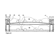
図3は、本発明の実施形態の透視図を示し、複数のデッキと、折り畳み式隅モジュール70として設計された対の支柱それぞれの上に置かれたデュアルスパン(40フィートと45フィートの長さの)キャプチャ及びハンドリング付属品とを有する。
FIG. 3 shows a perspective view of an embodiment of the present invention, with dual spans (40 feet and 45 feet long) placed on multiple decks and each of a pair of struts designed as a
より具体的には、ベース22は、ブレースで支えられたスチール波板のプラットフォーム・デッキ・フロア24の各側面にある、縦に直立したサイドレール23が作る浅い盆の形(shallow tray)をしている。
More specifically, the
内側の(底部)支柱25は、40フィートの長さの位置にあり、近接する外側の(底部)柱26は45フィートの長さの位置にある。
The inner (bottom)
底部柱25及び26は構造的に橋板47に接合されており、それにより、ベース22に載せられた隅柱モジュール70が統合する。
The
底部柱25及び26は、サイドレール23に取り付けられたヒンジ29によってベース22上に旋回軸取り付けされており、図8及び10が示すように、対のトーション・バー付勢バネ**が付随している。
The
底部柱25、26を、空洞(長方形または円形)の箱のセクションとして構成することができ、そこへ、それぞれ内側と外側の上部柱55及び56を順にはめ込むことによって、可動上部デッキ42を運ぶ。
The bottom posts 25, 26 can be configured as a section of a hollow (rectangular or circular) box that carries the movable
上部柱55、56は、キャプチャ上部付属品31及びハンドル上部付属品33により蓋をして閉じられる。
The
上部レール37は付属品31、33に接合し、(スプレッダ打撃)ガードバー38によって内側に延長される。
The
対(または単独)のアクセス用エンドゲート28は、反対側のデッキ端で外側底部柱26にヒンジ39で取り付けられている。
The pair (or single)
ヒンジ30により、ゲート28は270度回転することができ、互いに、若しくは反対側の柱26と接触する閉じた位置から、ベース22に沿って手前に開かれた位置(図示せず)まで旋回する。
The
ベースデッキ24の上には、やはり波板スチール製であるブレースされたプラットフォーム・デッキ・フロア43の対面する側部にある直立した長手方向のサイドレール49の可動上部デッキ42がある。
Above the
上部デッキ42は、取り外し可能なピン51によってサイドレール49に取り外し可能な方法で接続されているワイヤーケーブルまたはチェーン41により懸垂されており、ケーブル41は、内側の上部柱55上に取り付けられたプリー・ホイール39に乗って動く。
The
プリー39は柱55と上部付属品31の軸の近くに配置され、前記プリーはケーブル41を隅支柱モジュール70に近づける、若しくはその制限範囲内で動かす。
The
図10により更に明確に示すように、ケーブル41のもう一方の端は、アンカーピン53で内側底部柱25に固定されている。
As more clearly shown in FIG. 10, the other end of the
移動制限ストップ54は、底部柱25、26の一方または両方に取り付けられ、それにより、上部柱55、56を延長するためにケーブル41が解除されて獲得用付属品31、33が露出されたときに、図6が示すように上部デッキ42を支える。
The
制限ストップ54は、貨物がベースデッキ22に積載されたときに上部デッキ42の下方制限となるが、シングル・デッキとして作動する形態またはフラットラック全体を折り畳む前の準備段階として、上部デッキ42を下げてベースデッキ22の上に乗せるためには、前記制限ストップが解除される。
The
取り外し可能なデテント(戻り止め)58は、付随する底部及び上部柱25/55及び26/56を合体してロックするように作動可能である。
A
図4及び5は、まず上部デッキ42を動かし、次に上部デッキ積載物66を越えるところまで延びる上部支柱55、56の延長を示す。
4 and 5 show the extension of the
操作上は、横軸ヘッダービームまたはブレースがない状態では、上部デッキ42及びそれに付随する積載物(乗用車)66を、ベースデッキ22の上へ運び上げることが可能である。
In operation, in the absence of a horizontal header beam or brace, the
これにより、ベースデッキの積載物(乗用車)65を運転して載せ降ろしするために十分なスペースが車の頭上に与えられる。 Thus, sufficient space is provided above the head of the vehicle for driving and loading and unloading the load (passenger car) 65 on the base deck.
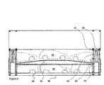
いったん両方のデッキ22、42へ貨物が積載されたら、図5が示すように上部デッキ42を下げてベースデッキ22に近づけることが可能である。
Once the cargo is loaded on both
この形態において、ベースデッキ22上の背の高い自動車65の屋根は、上部デッキ42のデッキ下部の制限をいくらか越えて入り込むことができ、それにより、積載物全体をコンパクトにまとめることができる。
In this configuration, the roof of the
上部デッキ42をロック64により制止させることができ、ピン51を解除することによってケーブル41の連結を解くことができる。
The
これにより、上部柱55、56の完全延長が可能となり、付随するキャプチャ付属品31、33を露出し、上部デッキ積載物(乗用車)66の上まで伸ばすことができる。
Accordingly, the
この形態においてコンテナ60は、スプレッダ(図示せず)による取り扱い、またはその上に積まれた対応するコンテナの支持が可能となる。
In this configuration, the
柱間デテント(戻り止め)
確実に固定するために、柱間デテント58を上部柱55、56とそれぞれ対応する底部柱25、26との間に係合し、サポート・ワイヤ41またはリフト・ラム35の折り畳みが失敗したときに作動する初期設定積載物運搬ストップとする。
Detent between pillars (detent)
In order to securely fix, the
いったん望ましい位置に上げられると、上部支柱55、56は、対応する整合された穴を貫通するデテント58によって、それぞれ対応する底部柱25、26にロックされる。
Once raised to the desired position, the top struts 55, 56 are locked to the corresponding bottom posts 25, 26, respectively, by
デテント58は、キャプチャ付属品31または33に置かれた揚重、振り、及び積み重ね負荷に耐える。
The
柱間デテント58は、望ましくは平面ラッチピンの形に作られ、それにより、負荷を拡散し、磨耗またはその場での焼き付きの危険を最小限にする。
The
リフト・ラム
油圧リフト・ラム35は、内側及び外側の底部支柱25、26の間に配置される。
Lift Ram A
延長可能なラム・ピストン36は、上部の内側及び外側の支柱55、56の間にあり、獲得ピン34によってバー37に固定されている。
リフト・ラム35は、隅モジュール70内のベースフレーム上にあり、獲得ピン34を介しバー37上で、例えばハンド・ポンプによって選択的に作動する。
The
ラム36の引き込みまたは延長は、上部柱55、56及び付随するプリー39を動かし、前記プリーは、前記ラム36が迅速なデッキ動作のために「届く距離」を倍にする作用により、ケーブル41の長さを伸縮させる。
Retraction or extension of the
U型デッキ
上部及びベースデッキ42、22は、一定のインターフィットに適した相補的な「U」型の横断面の輪郭である。
U-Deck The top and
従って、ケーブル41と、リフト・ラム35の後退とによって完全に下げられると、図10が示す部分的末端部の点線が示すように、上部デッキ42はベースデッキ22の輪郭が定める「U」型の盆の中に納められる。
Thus, when fully lowered by the
ガードバー38は、例えば横方向に不整合の40フィートスプレッダが上部デッキ積載物66と接触するのを防ぐ。
従って、積載物に損傷を与える危険を伴わずに、40フィートまたは45フィートのスプレッダを使うことが可能であり、この点が、図2が示すフラットラック18と異なる。
Therefore, it is possible to use a 40 foot or 45 foot spreader without the risk of damaging the load, which differs from the
柱ヒンジ
柱ヒンジ29は、水平長手方向の旋回ピン27軸を有し、それにより、底部柱25及び26はベースデッキ24に向けて横倒しに共に折り畳まれる。
Column Hinge Column hinge 29 has a horizontal
図6は、デッキの両側にある底部柱25、26のヒンジ29の異なる相対的高さを示す。
FIG. 6 shows the different relative heights of the
これにより、折り畳み式柱25、26が内側に横倒しに折り畳まれたときに互いに重なり合い、ベースデッキ22の範囲内に収まることが可能となる。
As a result, when the
ゲートロック
輸送及び荷物の取り扱いの際に支柱25、26を直立に維持するために、単独または複数のエンドゲート28が、合体させてロックされ及び/またはスピゴット52によって反対側の柱にロックされる。
Gate locks One or
柱とゲートが完全に内側に折り畳まれると、それらはロック57によって下部のベースデッキ24に固定され、堅固なブレース構造を作り出す。
When the column and gate are fully folded inward, they are secured to the
スタブ柱
それぞれの上部獲得・取り扱い付属品68とともに残された直立スタブ柱67は、横倒しに内側に折り畳まれた支柱25、26より上に突き出る。
Stub Columns The
これにより、図9が示すように、内部の付属品に接触損傷を与えずに相互に積み重ねることが可能になる。 Thereby, as FIG. 9 shows, it becomes possible to mutually stack | stack without giving a contact damage to an internal accessory.
これらスタブ柱67には、苛酷な振れ・積み重ね負荷がかかるが、前記スタブ柱は、インターロックした柱、ゲート、及びデッキ構造によって支えられている。
These
図7では、エンドゲート28は180度まで開かれており、これによりベース22のフロア24へ貨物を積載することが可能となる。
In FIG. 7, the
上部デッキ42のデッキフロア44は上に揚げられた位置で示されており、これにより、フロア23上の乗用車66の下を通り、乗用車65を運転して載せ降ろしすることが可能である。
The deck floor 44 of the
図8は、図6及び7に対応する端面図を示しているが、上部隅支柱延長部55,56は、それぞれの底部隅支柱25、26の中に引き込まれている。
FIG. 8 shows an end view corresponding to FIGS. 6 and 7, but the top
エンドゲート28は270度まで手前に開かれており、フラットラック60の縦の側面に沿って置かれている。
The
上部デッキ42は下げられており、そのフロア面44はベースデッキ・フロア24上にある。
The
フラットラック22を折り畳むために、柱25及び26は、図面においてフロア24に向かう矢印A及びBが示すように、それぞれ左からと右から互い違いに内側に折り畳まれる。
In order to fold the
ガードバー38と上部レール37は、前記隅柱25、26と共に容易に折り畳まれ、それに伴って1若しくはそれ以上のエンドゲート28が折り畳まれ、全体にコンパクトな折り畳みモジュール60の輪郭の中に納まる。
シングル・エンドゲート28の底部支柱が先に折り畳まれると、ゲート28は、それが取り付けられた柱及び上に重なっている柱の両方の下に置かれる。
The
When the bottom column of single-ended
傾斜台になったベースデッキ24の輪郭により、底部柱25、25はベースのサイドレール23の深さに納まるように折り畳まれる。
The
一体型支柱
個別の柱25/55、26/56を、1つの柱に一体化することが考えられる。
Integrated column It is conceivable to integrate the
45フィート及び40フィート長用キャプチャ付属品31、33を、上部レール37またはガードバー38に沿って(再)配置することが可能である。
The 45 foot and 40 foot
スタック
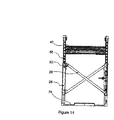
図8は、平坦に折り畳まれたフラットラック60を5つ積み重ねたスタック80の端面図であり、上述のように、それぞれの支柱25及び26は内側に折り畳まれている。
Stack FIG. 8 is an end view of a
スタック80全体の深さは、立ち上げられた1つのフラットラック60の深さに総じて等しく、上部柱55、56はそれぞれの底部柱25、26内に引き込められている。
The depth of the
フラットラック60が、それぞれに近接するキャプチャ付属品68を介して相互連結されることにより、一体化されたスタック・アセンブリ80を作ることが可能であり、最上部にある付属品68によって取り扱うことが可能である。
The
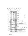
図10は、側面の一部を拡大し、フラットラック60の一方の端にある隅支柱モジュールの詳細を示している。
FIG. 10 shows a detail of the corner post module at one end of the
隅柱25、26は、立ち上げられ、合体してロックされているか、若しくはゲートがヒンジで接続されている柱の反対側の柱にロックされている1若しくはそれ以上のエンドゲート28によりロックされている。
The corner posts 25, 26 are raised and united and locked, or locked by one or
柱55、56は、上部レール37、キャプチャ付属品31、33、及びガードレール38と共に、点線37’が示す完全に引き込まれた位置から上に上げられている。
ポンプ駆動式の油圧ラム35は、柱25、26内部で柱55、56を動かす。
The pump-driven
ラム・ピストン・ロッド36は、上部レール37にあるピン34を介して作動し、上部レール37を押し上げ、上部構造60(要素55、56、37、及び38を含む)を上昇させる。
The
柱55、56がいったん望ましい高さに上昇したら、柱55、56を、軸48で作動するデテント58によってその位置にロックすることができる。
Once the
上部支柱55、56を引き込めるには、デテント58を引き込めることにより、重力の作用でラム・ピストン36を引き込めるか、ラム35シリンダー排気ポンプ作用によりそれを行うか、またはその両方を行う。
To retract the
上部支柱55、56の上昇と下降は、追加的機能を有する。
The raising and lowering of the
プリー・ホイール39は、ブラケット49によってバー37に取り付けられている。
The
前記プリー39には、上部デッキ42の一方の端**に止められているチェーンまたはワイヤ・ロープ41がかけられており、もう一方の端はピン63によって柱25に固定されている。
A chain or
ラム35が上部支柱55、56を上下するにつれ、ベース22に納まっている最低位42’から望ましい高さ42"まで、ワイヤ41は前記動作を上部デッキ42に伝達する。
As the
いったん望ましい高さになったデッキ42は、柱25にあるデッキロック64によって定位置に止めることが可能であり、それによりデッキ42を輸送用に固定することができる。
Once the desired height is reached, the
詳述した前記フラットラック60は、伸縮自在の隅支柱55、56を有するが、高さの固定した隅支柱を使うことも考えられる。
The
その他の実施形態には、デッキ24上の乗用車66の傾斜を最大にするように形作ったデッキ24表面が含まれる。
Other embodiments include a
この事例において、可動上部デッキ42はサイドレール43の上部端にプラットフォーム充填物を有し、それにより、下部のベースデッキ22にある貨物の頭上空間が大きくなる。
In this case, the movable
図5が示すように、局所的に上部デッキフロア24の一部若しくは全部を、間隔を空けて置かれた横軸バー61と交換することにより、個々の乗用車66の車輪を捉えて支えることが可能である。
As shown in FIG. 5, it is possible to catch and support the wheels of
バー61をデッキ22に固定せず、調整可能にすることにより、上部デッキ42をベース22から離して上昇させたときに乗用車66を選択的に局部傾斜させることができる。
By allowing the bar 61 to be adjusted without being fixed to the
組み込まれるラム35またはプリー・ホイール39、及びケーブルまたはチェーン41は不可欠ではない。
The incorporated
むしろ、クレーン、フォークトラック、または何らかの他の特殊装置のような外部または補助的手段によって上部デッキ42を上昇させ、下降させることが可能である。
Rather, the
ベースデッキ22及び可動上部デッキ42の長さを調整可能とすること(伸縮自在にすること)が可能である。
It is possible to adjust the lengths of the
従って、45フィートのフラットラックを延長または引き込むことにより別の長さにすることが可能である。 It is therefore possible to extend or retract a 45 foot flat rack to another length.
40フィート及び45フィート長は、広く採用されている標準的な長さであるが、他の長さも可能である。 40 feet and 45 feet long are standard lengths that are widely adopted, but other lengths are possible.
上部デッキ42を高いレベルに上昇させ、下部デッキ貨物の保護カバーまたは屋根とすることが可能である。
The
エンドゲート28を全部または部分的に充填またはパネル付けし、貨物を保護することができる。
The
柱55の間でガードバー38からサイドカーテンを下げ、下部サイドレール23に接続することにより、閉じられた貨物室を作ることができる。
By closing the side curtain from the
デッキ42の一端をもう一方の端よりも先に上昇させ、傾斜したスロープを乗用車26が上がるようにすれば、ラム35の上昇作業が軽減される。
If one end of the
入れ子状になったベース及び上部デッキ22、42の共同作用が可能であり、一体化された構造物としてロックすれば、より大きく重い自動車または貨物を支えることができる。
Nested bases and
(直立)柱15,16の間隔よりも幅の広い自動車は、図面に描かれた垂直の位置を越えて斜めに押し出すことにより、前記柱の間を通過することができる。
A car that is wider than the spacing between the (upright)
実際、柱は、例えば水平な位置まで外側に広げる(折り倒す)ことが可能であり、それにより、ベース14の内側の幅よりも大きいアクセス幅が得られる。 In fact, the pillar can be expanded outward (folded down), for example, to a horizontal position, thereby providing an access width that is greater than the inner width of the base 14.
デッキ42は取り外し可能である。
The
デッキフロア24、44は、複数の分離した要素によって構成することが可能であり(ただし端は相互連結している)、それにより局所的に個別にスロープを調整すれば、異なる形状及びサイズの乗用車を積載することが更に容易になる。
The
デッキ端の傾斜台の代替物及び中間トラップドアについては後に説明する。 Alternative deck ramps and intermediate trap doors will be described later.
プリーの設置
望ましくはケーブル移動プリーは、前記ピストン・ラム軸センターライン上またはその近くに取り付けられる。
Pre-installation Preferably, the cable travel pulley is mounted on or near the piston ram shaft centerline.
柱ベース旋回軸
望ましくは柱ベース旋回軸も、前記柱軸またはセンターライン上またはその近くに取り付けられる。
背が高く先細りの形の自動車
いわゆるワンボックスカーまたは多目的車(MPV)のように、背が高く、より直立した形の自動車は、背の高い後部端(テールゲート)から、浅いフロント・ボンネットに向けていくらか先細りの輪郭をしている。
Column-based swivel axis Preferably a column-based swivel axis is also mounted on or near the column axis or centerline.
Tall and tapered cars, such as so-called one-box cars or multipurpose vehicles (MPVs), taller and more upright cars, from the tall rear end (tailgate) to the shallow front bonnet It has a somewhat tapered outline.
輸送中の位置にある積載物の高さまたはデッキ間の頭上空間は、全体に等しい深さであるため、背の高い自動車には不十分であるか、前述のように複数積載するときに非効率的に空間が占有される可能性がある。 The height of the load in the position being transported or the overhead space between the decks is the same depth as the whole, so that it is not sufficient for tall cars or is not suitable for multiple loading as described above. Space can be efficiently occupied.
出願人が先に提出した「マルチデッキ(Multi−Deck)」国際出願番号第PCT/GB97/02319号は、デッキ部分と付随する相対的な積載物傾斜及び再配向によって、より高い密度で入れ子状に積載する方法を構想している。 “Multi-Deck” International Application No. PCT / GB97 / 02319, previously filed by the applicant, is nested at higher densities due to the relative load slope and reorientation associated with the deck portion. I envision how to load it.
デッキ端の傾斜
デッキ端の傾斜により、端にある自動車の後輪がやや低く置かれる。
Deck edge inclination The deck edge inclination places the rear wheel of the car slightly lower.
これには、完全に分離されたデッキが一端から逆になるように、端の最も近くに載せられる自動車を、それぞれの端から前向きに載せる必要がある。 This requires that the car that is mounted closest to the end be mounted forward from each end so that the fully separated deck is reversed from one end.
デッキ・トラップドア
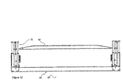
同様に、(図13の上部デッキの69のような)デッキ・トラップドアを取り付けることにより、背の高い(後部)車両端にある車輪がデッキの中のより低い位置に置かれ、前記屋根の輪郭は、用意された積載物の高さに合わせやすくなる。
Deck Trap Door Similarly, by installing a deck trap door (such as 69 in the upper deck in Figure 13), the wheels on the tall (rear) vehicle end are placed lower in the deck. The outline of the roof can be easily adjusted to the height of the prepared load.
これには、デッキ積載空間の垂直方向が含まれる。 This includes the vertical direction of the deck loading space.
種々の組み合わせ
具体的に記述される様々な特徴を、選択的に「種々の組み合わせ」をすることができるが、実行可能なすべての組み合わせを本書に含めるのは実際的ではない。
コンポーネント一覧
10 プラットフォーム・ベース
12 隅柱
13 上部キャプチャ及びハンドリング付属品
14 上部アパーチャ
15 底部キャプチャ付属品
16 乗用車貨物積載物
18 フラットラック
19,19’ クレーン・リフト・スプレッダ
20,20’ キャプチャ付属品(スプレッダ19)
21 セルガイド
22 ベース
23 縦のサイドレール
24 プラットフォーム・デッキ・フロア
25 (内側)底部支柱
26 (外側)底部支柱
27 旋回ピン
28 エンドゲート
29 柱ヒンジ
30 ゲートヒンジ
31 上部キャプチャ及びハンドリング付属品
33 上部キャプチャ及びハンドリング付属品
34 キャプチャ・ピン
35 リフト・ラム
36 ラム・ピストン
37 バー
38 ガードバー
39 プリー
41 ワイヤーケーブル/チェーン
42,42’ (可動)上部デッキ(+42")
43 サイドレール
44 デッキ
45 ラム・フレーム
46 隅支柱エンドフレーム
47 橋板
48 デテント(58)軸
49 プリー・ブラケット
50 フラットラック
51 取り外し式ケーブルピン
52 ゲート・スピゴット・ロック
53 ケーブル・アンカーピン
54 移動制限ストップ
55 (内側)上部柱
56 (外側)上部柱
57 ゲート・柱・デッキロック
58 柱間デテント
59 付勢バネ
60 フラットラック
61 デッキ・バー
62 バー位置
64 (上部)デッキロック
65 (底部デッキ)乗用車積載物
66 (上部デッキ)乗用車積載物
67 スタブ柱
68 キャプチャ及びハンドリング付属品
69 (デッキ)トラップドア
70 隅支柱モジュール
80 スタック
21
43 Side rail 44 Deck 45
Claims (26)
プラットフォーム・デッキまたはフラットラック・コンテナであって、
キャプチャ及びハンドリング付属品を有し、
異なる長さで配置されているものである。 {Capture different lengths}
A platform deck or flat rack container,
With capture and handling accessories,
They are arranged with different lengths.
請求項1のフラットラックにおいて、
キャプチャ及びハンドリング付属品を有し、
異なる長さ標準によって集められたものである。 {Gathering accessories}
The flat rack of claim 1,
With capture and handling accessories,
Collected by different length standards.
上記請求項のいずれかのフラットラックにおいて、
それぞれの支柱と、
付随のキャプチャ及びハンドリング付属品とを有し、
異なる長さであるものである。 {Distances and accessories of different lengths}
In the flat rack of any of the above claims,
Each strut,
With accompanying capture and handling accessories,
Are of different lengths.
上記請求項のいずれかのフラットラックにおいて、
複数の支柱を有し、
1つの柱モジュール内に、
デッキ端においてまたはデッキ端に近接して集められているものである。 {Multiple assembly struts}
In the flat rack of any of the above claims,
Have multiple struts,
In one pillar module,
Collected at or near the deck edge.
上記請求項のいずれかのフラットラックにおいて、
独立した折り畳み式支柱集合を有するものである。 {Independent foldable strut assembly}
In the flat rack of any of the above claims,
It has an independent folding column set.
上記請求項のいずれかのフラットラックにおいて、
キャプチャ及びハンドリング付属品を有し、
40フィート及び45フィート長さの両方で、
2つの取り扱い標準を満たすものである。 {40 feet and 45 feet accessories}
In the flat rack of any of the above claims,
With capture and handling accessories,
Both 40 feet and 45 feet long,
It meets two handling standards.
上記請求項のいずれかのフラットラックにおいて、
対面する側に支柱を有し、
旋回軸が取り付けられており内側に横倒しに折り畳まれて、
プラットフォーム・デッキ上に互いに重なり合うものである。 {Stands folded sideways}
In the flat rack of any of the above claims,
It has a support on the facing side,
A swivel axis is attached and folded inward on the inside,
They overlap each other on the platform deck.
上記請求項のいずれかのフラットラックにおいて、
異なる高さに支柱旋回軸を有し、
互いに重なり合って折り畳まれるものである。 {Column swivel axes with different heights}
In the flat rack of any of the above claims,
With column pivots at different heights,
They overlap each other and are folded.
上記請求項のいずれかのフラットラックにおいて、
支柱旋回軸取り付け部分を有し、
トーション・バーばねにより付勢されており、
柱の重量と平衡するものである。 {Equilibration of torsion bar pillar}
In the flat rack of any of the above claims,
It has a strut turning shaft mounting part,
It is energized by a torsion bar spring,
It is balanced with the weight of the pillar.
上記請求項のいずれかのフラットラックであって、
積載された油圧ラムと
ケーブル・プリー・ドライブ連結とを有し、
支柱延長と、
懸垂されたデッキとの移動を行うものである。 {Ram and cable pulley deck suspension}
A flat rack according to any of the preceding claims,
It has a loaded hydraulic ram and cable pulley drive connection,
Strut extension,
It moves with the suspended deck.
上記請求項のいずれかのフラットラックにおいて、
対の伸縮自在の支柱を有し、
ジョイント・ラムとケーブル・ドライブとにより作動可能であり、
それぞれのキャプチャ及びハンドリング付属品を、
異なる標準長さで有するものである。 {Pair of pairs}
In the flat rack of any of the above claims,
With a pair of telescopic struts,
Operable with joint ram and cable drive,
Each capture and handling accessory,
Have different standard lengths.
上記請求項のいずれかのフラットラックにおいて、
可動デッキを有し、
各隅においてまたは各隅に近接して置かれた、
長さ調整可能な対の支柱によって運ばれ、
前記対の支柱はそれぞれのキャプチャ及びハンドリング付属品を、
異なる長さで有するものである。 {Length adjustable pair of struts}
In the flat rack of any of the above claims,
Has a movable deck,
Placed at or near each corner,
Carried by twin struts adjustable in length and
The pair of struts has their respective capture and handling accessories,
Have different lengths.
上記請求項のいずれかのフラットラックにおいて、
可動上部デッキを有し、
支柱によって運ばれ、
前記支柱はベースデッキに載っているものである。 {Moveable upper over base deck}
In the flat rack of any of the above claims,
Has a movable upper deck,
Carried by props and
The column is mounted on the base deck.
上記請求項のいずれかのフラットラックにおいて、
末端アクセス閉鎖ゲートを有し、
対の支柱の間に、
それぞれのキャプチャ及びハンドリング付属品を、
各デッキ端の対面する側に有するものである。 {Terminal access gate}
In the flat rack of any of the above claims,
Has a terminal access closure gate,
Between the pair of struts,
Each capture and handling accessory,
Each deck end has a facing side.
上記請求項のいずれかのフラットラックにおいて、
デッキの端が先細りに形成されており、
それにより自動車貨物用の末端傾斜台が作られ、
コンパクトに収納するために自動車を傾けることが、
フラットラック・デッキの限られた空間で可能となるものである。 {Deck tilt}
In the flat rack of any of the above claims,
The edge of the deck is tapered,
As a result, an end ramp for automobile cargo was created,
Tilting the car to store it compactly,
This is possible in the limited space of a flat rack deck.
上記請求項のいずれかのフラットラックにおいて、
デッキフロアにヒンジ取り付けされたトラップドアを、
デッキフロア中間のデッキ端に有し、
自動車貨物の局所的傾斜が可能となり、
その上に車輪が置かれるものである。 {Deck trap door}
In the flat rack of any of the above claims,
A trap door hinged on the deck floor
At the deck end in the middle of the deck floor,
Allowing local inclination of automobile cargo,
Wheels are placed on it.
上記請求項のいずれかのフラットラックにおいて、
複数のキャプチャ及びハンドリング付属品を有し、
個々の支柱によって運ばれるものである。 {Multiple capture accessories for each pillar}
In the flat rack of any of the above claims,
Has multiple capture and handling accessories,
It is carried by individual struts.
上記請求項のいずれかのフラットラックにおいて、
支柱延長ラムを有し、
柱の領域内に配置されるものである。 {Extension ram in pillar}
In the flat rack of any of the above claims,
With a strut extension ram,
It is arranged within the column area.
上記請求項のいずれかのフラットラックにおいて、
ケーブル・サスペンションを有し、
支柱の領域内に配置されるものである。 {In-pillar cable suspension}
In the flat rack of any of the above claims,
With cable suspension,
It is arranged in the area of the column.
上記請求項のいずれかのフラットラックにおいて、
デュアル・インターフィッティング・デッキを有し、
長さ調整可能な支柱の間で運ばれ、
前記支柱が旋回軸取り付けされており内側に横倒しに折り畳まれることにより、
全体がコンパクトに折り畳まれ、
互いに重なり合うデッキ内に支柱を有するものである。 {Dual Interfitting Deck}
In the flat rack of any of the above claims,
Has a dual interfitting deck,
Carried between length adjustable struts,
The support column is attached to the pivot and is folded inward on the inside,
The whole is folded compactly,
It has a support | pillar in the deck which mutually overlaps.
上記請求項のいずれかのフラットラックにおいて、
選択的に作動可能なデッキロックを有する。 {Deck Rock}
In the flat rack of any of the above claims,
Has a selectively actuable deck lock.
上記請求項のいずれかのフラットラックにおいて、
選択的に作動可能な折り畳み式インターロックを有し、
内側に折り畳まれた支柱の間と、それによって運ばれるゲートと、
下部デッキとに取り付けられる。 {Foldable interlock}
In the flat rack of any of the above claims,
Has a selectively actuable folding interlock,
Between the struts folded inside and the gate carried by it,
Attached to the lower deck.
上記請求項のいずれかのフラットラックにおいて、
折り畳み支柱と、
下部デッキの相互作用とを有し、
残りの隅スタブ柱と、
付随のキャプチャ及びハンドリング付属品とを支えるものである。 {Folding stub pillar brace}
In the flat rack of any of the above claims,
Folding stand,
With lower deck interaction,
The remaining corner stub pillars,
Supports accompanying capture and handling accessories.
上記請求項のいずれかのフラットラックにおいて、
可動デッキ・オーバートラベル設備を有し、
デッキ荷役を容易にするものである。 {Movable deck overtravel}
In the flat rack of any of the above claims,
It has a movable deck and overtravel equipment,
It makes deck handling easier.
上記請求項のいずれかのフラットラックにおいて、
可動デッキ・オーバートラベル・ロックを有し、
それによりデッキ荷役アクセスを固定する。 {Deck Overtravel Rock}
In the flat rack of any of the above claims,
It has a movable deck, overtravel lock,
This fixes the deck handling access.
本書において前述したフラットラックは、
添付の図面を参照して説明され、且つ示される。 {Embodiment of Figure}
The flat rack mentioned earlier in this document is
It will be described and illustrated with reference to the accompanying drawings.
Applications Claiming Priority (2)
| Application Number | Priority Date | Filing Date | Title |
|---|---|---|---|
| GBGB0226012.3A GB0226012D0 (en) | 2002-11-07 | 2002-11-07 | A car carrying container |
| PCT/GB2003/004805 WO2004041679A1 (en) | 2002-11-07 | 2003-11-05 | Collapsible flat rack |
Publications (2)
| Publication Number | Publication Date |
|---|---|
| JP2006505460A true JP2006505460A (en) | 2006-02-16 |
| JP2006505460A5 JP2006505460A5 (en) | 2006-12-21 |
Family
ID=9947408
Family Applications (1)
| Application Number | Title | Priority Date | Filing Date |
|---|---|---|---|
| JP2004549360A Pending JP2006505460A (en) | 2002-11-07 | 2003-11-05 | Foldable flat rack |
Country Status (9)
| Country | Link |
|---|---|
| US (2) | US20060104755A1 (en) |
| EP (1) | EP1567429B1 (en) |
| JP (1) | JP2006505460A (en) |
| CN (1) | CN100463817C (en) |
| AT (1) | ATE367329T1 (en) |
| AU (1) | AU2003276480A1 (en) |
| DE (1) | DE60315065T2 (en) |
| GB (1) | GB0226012D0 (en) |
| WO (1) | WO2004041679A1 (en) |
Cited By (1)
| Publication number | Priority date | Publication date | Assignee | Title |
|---|---|---|---|---|
| KR101556396B1 (en) * | 2014-07-04 | 2015-09-30 | 김규완 | Container for automobiles |
Families Citing this family (38)
| Publication number | Priority date | Publication date | Assignee | Title |
|---|---|---|---|---|
| GB0226012D0 (en) * | 2002-11-07 | 2002-12-18 | Clive Smith Martin | A car carrying container |
| CN100398415C (en) * | 2004-07-23 | 2008-07-02 | 中国国际海运集装箱(集团)股份有限公司 | Platform type container for transporting large cylindrical goods |
| US8915684B2 (en) | 2005-09-27 | 2014-12-23 | Fontaine Trailer Company, Inc. | Cargo deck |
| US7544027B2 (en) * | 2007-04-28 | 2009-06-09 | James Barker | System and method for loading vehicles onto the cargo bed of a transporting vehicle |
| NL1034670C2 (en) * | 2007-11-12 | 2009-05-14 | Arie Van Donge B V | Flat container and method for transporting vehicles. |
| US8790062B2 (en) * | 2008-04-01 | 2014-07-29 | Mi-Jack Products, Inc. | Distribution system |
| DE102008029075B3 (en) * | 2008-06-10 | 2010-01-21 | WAP Wöhr Automatikparksysteme GmbH & Co KG | Park for motor vehicles |
| US20110073595A1 (en) * | 2009-09-30 | 2011-03-31 | Murray Crane | Collapsible freight container |
| US8714895B2 (en) | 2010-09-29 | 2014-05-06 | Raildecks (2009), Inc. | Collapsible intermodal transport platform |
| US8353647B2 (en) | 2010-09-29 | 2013-01-15 | Raildecks (2009), Inc. | Collapsible intermodal transport platform |
| US9004832B1 (en) | 2012-05-14 | 2015-04-14 | Raildecks (2009), Inc. | Intermodal container |
| MX2015005784A (en) | 2012-11-09 | 2015-12-17 | Fontaine Engineered Products Inc | Collapsible intermodal flat rack. |
| CN104837725B (en) | 2012-12-12 | 2018-11-30 | 欧申奈克斯公司 | flat bracket |
| NO335191B1 (en) * | 2012-12-19 | 2014-10-20 | Polotec As | Transfer station for vehicles |
| CN103072765B (en) * | 2013-01-28 | 2014-12-31 | 浙江双友物流器械股份有限公司 | Layering device used in container |
| TWI488798B (en) * | 2013-02-01 | 2015-06-21 | Ming Lurn Prec Machine Co Ltd | Vehicle lift transmission mechanism and vehicle lift comprising the same |
| CN103274138B (en) * | 2013-05-28 | 2015-09-09 | 浙江双友物流器械股份有限公司 | A kind of for the decker in container |
| CN104648449A (en) * | 2013-11-18 | 2015-05-27 | 铜陵市大明玛钢有限责任公司 | Steel pipe carrying cart |
| US20150368035A1 (en) * | 2014-06-19 | 2015-12-24 | Innovative Trailer Design Technologies Inc. | Intermodal shipping container box |
| US20160278516A1 (en) * | 2015-03-26 | 2016-09-29 | James Lawrence | Product shipping system |
| WO2016181023A1 (en) * | 2015-05-13 | 2016-11-17 | Outotec (Finland) Oy | A flotation plant and its uses, a method of changing a flotation tank in a tank module and a method of changing a module |
| CN107672956B (en) | 2016-08-01 | 2020-09-04 | 南通中集特种运输设备制造有限公司 | Double-layer foldable frame box |
| ES2594802B1 (en) * | 2016-08-23 | 2017-09-26 | J.S.V. Logistic, S.L. | OPEN CONTAINER WITH SWING COVER |
| US10035464B2 (en) | 2016-08-26 | 2018-07-31 | Toyota Motor Engineering & Manufacturing North America, Inc. | Multi-level rear storage systems and methods for vehicles |
| CN106329390B (en) * | 2016-11-02 | 2018-06-29 | 国网江苏省电力公司仪征市供电公司 | A kind of vehicle-mounted crossing frame |
| GB2555792A (en) * | 2016-11-08 | 2018-05-16 | Tiger Trailers Ltd | Lifting mechanism for a double-deck container for transportation of goods |
| EA039688B1 (en) * | 2017-03-21 | 2022-02-28 | Спектейнер Пти ЛТД | Collapsible intermodal container and collapsible intermodal container assembly |
| CN107381388A (en) * | 2017-09-01 | 2017-11-24 | 宁津县万发机械有限责任公司 | A kind of container modularization liftable cable reel |
| CN109987351A (en) * | 2017-12-29 | 2019-07-09 | 广东新会中集特种运输设备有限公司 | Folding carton |
| CN108035578A (en) * | 2018-01-09 | 2018-05-15 | 何照纯 | A kind of collapsible shared bicycle intelligent stereo garage |
| AU2018271285B2 (en) * | 2018-03-24 | 2022-08-04 | David CEROCCHI | Transport trailer |
| CN109110322B (en) * | 2018-09-14 | 2020-12-18 | 谢永琴 | Automatic charging management and control flat cabinet with protection assembly |
| KR20210126139A (en) * | 2019-03-04 | 2021-10-19 | 굿팩 아이비씨 (싱가포르) 피티이. 엘티디. | cargo unit |
| IL267832B2 (en) * | 2019-07-03 | 2023-05-01 | Fridenson Logistics services Ltd | Train wagon car carrier adapted for forklift lifting |
| RU2743296C2 (en) * | 2019-08-09 | 2021-02-16 | Акционерное общество "Завод металлоконструкций" | Pallet for locating and fixating an automobile semi-trailer on a flat wagon |
| CN110589270A (en) * | 2019-08-29 | 2019-12-20 | 广东新会中集特种运输设备有限公司 | Platform type container |
| DE102021205134A1 (en) | 2021-05-20 | 2022-11-24 | Psa Automobiles Sa | Transport vehicle and method of operation therefor |
| CN116118603B (en) * | 2023-04-17 | 2023-06-20 | 成都成飞航空产业发展有限责任公司 | Aircraft skin transfer system |
Family Cites Families (37)
| Publication number | Priority date | Publication date | Assignee | Title |
|---|---|---|---|---|
| US2128376A (en) * | 1936-01-06 | 1938-08-30 | Worth Co | Car loading device |
| US2523271A (en) * | 1944-10-25 | 1950-09-26 | Bartel Arthur | Load supporting pallet |
| US3480174A (en) * | 1967-08-02 | 1969-11-25 | James B Sherwood | Assembly of freight containers and foundation frame for use therewith |
| US3801177A (en) * | 1971-06-04 | 1974-04-02 | Fmc Corp | Frameless shipping container |
| US3830381A (en) * | 1972-04-27 | 1974-08-20 | Sea Land Service | Truck and outsize cargo container |
| US3807581A (en) * | 1972-11-07 | 1974-04-30 | Pullman Inc | Pallet with adjustable height legs |
| US4049149A (en) * | 1975-11-24 | 1977-09-20 | William Brener | Freight container universal corner |
| US4116135A (en) * | 1976-11-01 | 1978-09-26 | Southern Pacific Transportation Company | Sliding screen closure for rail cars |
| US4151925A (en) * | 1978-03-27 | 1979-05-01 | Pullman Incorporated | Flatrack container |
| NO159785C (en) * | 1979-10-16 | 1989-02-08 | Peter Howe | ADDITIONAL LOADING DEVICE. |
| GB2112356B (en) * | 1981-12-23 | 1985-06-19 | Boughton T T Sons Ltd | Improvements in or relating to transport frames for vehicles |
| FR2577534A1 (en) * | 1985-02-14 | 1986-08-22 | Weidmann Pittet Sa | NON-REUSABLE, HIGH CAPACITY INTERMODAL PACKAGING |
| US4714169A (en) * | 1987-03-26 | 1987-12-22 | Chrysler Motors Corporation | Collapsible/expandable shipping rack |
| US4986705A (en) * | 1987-11-25 | 1991-01-22 | Eis Corporation | Stackable freight container for holding stacked chassis |
| US4913061A (en) * | 1988-09-27 | 1990-04-03 | Youngblood Bernard J | Auto rack side panel support system |
| US5253975A (en) * | 1989-12-21 | 1993-10-19 | Taiyo Seiki Iron Works Co., Ltd. | Car loading apparatus |
| CA2091824A1 (en) * | 1992-03-18 | 1993-09-19 | Martin Clive-Smith | Freight container |
| US5394956A (en) * | 1993-08-30 | 1995-03-07 | Hulse; James M. | Suspended tender box |
| US5730578A (en) * | 1995-02-15 | 1998-03-24 | Wabash National Corporation | Lifting mechanism for a deck system |
| FR2741034B1 (en) * | 1995-11-13 | 1998-01-02 | Lohr Ind | STRUCTURAL EQUIPMENT FOR A ROAD VEHICLE PROVIDING AN ADDITIONAL MOBILE FLOOR |
| US5688086A (en) * | 1996-02-16 | 1997-11-18 | Aluminum Company Of America | Standard corner fittings for aluminum container frames |
| DE19730165A1 (en) * | 1997-07-14 | 1999-01-21 | Juergen Dipl Ing Gloystein | Device for transporting vehicles, in particular passenger cars, vans or the like |
| GB2329630A (en) * | 1997-09-24 | 1999-03-31 | Clive Smith Martin | Side-loading multi-deck container |
| IL126467A0 (en) * | 1998-10-06 | 1999-08-17 | Mifned Ltd | Sea/land going container for vehicle |
| GB2345282B (en) * | 1998-12-30 | 2001-09-05 | Kim Jum Gyu | Variable height container for vessel |
| GB9911483D0 (en) * | 1999-05-17 | 1999-07-14 | Clive Smith Martin | Vehicle mounting in container |
| GB2353031B (en) * | 1999-05-12 | 2003-12-31 | Martin Clive-Smith | Container with adjustable configuration |
| US6866160B2 (en) * | 2000-01-21 | 2005-03-15 | Feng Wang | Folding structure for foldable container |
| EP1326791B1 (en) * | 2000-10-03 | 2006-06-07 | Martin Clive-Smith | Vehicle support frame |
| GB0024214D0 (en) * | 2000-10-03 | 2000-11-15 | Clive Smith Martin | A frame to extend a container height |
| EP1358116A4 (en) * | 2001-02-09 | 2006-09-13 | Jum-Gyu Kim | Container for ship capable of height adjustment |
| US6533510B2 (en) * | 2001-07-23 | 2003-03-18 | International Transport Logistics, Inc. | Carrier for a trailer, system thereof using a stacking device, and method thereof |
| US6814529B2 (en) * | 2002-04-08 | 2004-11-09 | Friedola Gebr, Holzapef Gmbh & Co. Kg | Transport container for unit goods |
| GB0226012D0 (en) * | 2002-11-07 | 2002-12-18 | Clive Smith Martin | A car carrying container |
| GB0304780D0 (en) * | 2003-03-03 | 2003-04-09 | Clive Smith Martin | Demountable drive |
| US7040848B2 (en) * | 2003-07-21 | 2006-05-09 | Itl Technologies, Inc. | Transport platform |
| US6904857B1 (en) * | 2004-02-05 | 2005-06-14 | Gregory Aaron Holden | Boat lift securing device |
-
2002
- 2002-11-07 GB GBGB0226012.3A patent/GB0226012D0/en not_active Ceased
-
2003
- 2003-11-05 EP EP03810535A patent/EP1567429B1/en not_active Expired - Lifetime
- 2003-11-05 AT AT03810535T patent/ATE367329T1/en not_active IP Right Cessation
- 2003-11-05 WO PCT/GB2003/004805 patent/WO2004041679A1/en active IP Right Grant
- 2003-11-05 CN CNB2003801025913A patent/CN100463817C/en not_active Expired - Fee Related
- 2003-11-05 DE DE60315065T patent/DE60315065T2/en not_active Expired - Lifetime
- 2003-11-05 AU AU2003276480A patent/AU2003276480A1/en not_active Abandoned
- 2003-11-05 US US10/533,987 patent/US20060104755A1/en not_active Abandoned
- 2003-11-05 JP JP2004549360A patent/JP2006505460A/en active Pending
-
2007
- 2007-05-10 US US11/746,780 patent/US20070206999A1/en not_active Abandoned
Cited By (1)
| Publication number | Priority date | Publication date | Assignee | Title |
|---|---|---|---|---|
| KR101556396B1 (en) * | 2014-07-04 | 2015-09-30 | 김규완 | Container for automobiles |
Also Published As
| Publication number | Publication date |
|---|---|
| EP1567429B1 (en) | 2007-07-18 |
| GB0226012D0 (en) | 2002-12-18 |
| CN100463817C (en) | 2009-02-25 |
| US20060104755A1 (en) | 2006-05-18 |
| ATE367329T1 (en) | 2007-08-15 |
| CN1708441A (en) | 2005-12-14 |
| US20070206999A1 (en) | 2007-09-06 |
| DE60315065D1 (en) | 2007-08-30 |
| DE60315065T2 (en) | 2008-03-20 |
| EP1567429A1 (en) | 2005-08-31 |
| WO2004041679A1 (en) | 2004-05-21 |
| AU2003276480A1 (en) | 2004-06-07 |
Similar Documents
| Publication | Publication Date | Title |
|---|---|---|
| JP2006505460A (en) | Foldable flat rack | |
| US5275301A (en) | Collapsible freight container with gates | |
| US7025546B2 (en) | Vehicle support frame | |
| US7186065B2 (en) | Vehicle support frame | |
| RU2584043C2 (en) | Folding intermodal transport platform | |
| US10632894B2 (en) | Two-level pallet for stackable loading | |
| RU2500553C2 (en) | Handling device | |
| US6644704B1 (en) | Extendable truck rack | |
| AU778189B2 (en) | Adjustable post for container | |
| AU739733B2 (en) | Multi-deck container | |
| WO2006005920A1 (en) | Over-length log rack | |
| CA2944316C (en) | Cage assembly for use with pivotal gangway | |
| US20040188433A1 (en) | Convertible, transport, cargo box system | |
| US6634689B1 (en) | Retractable truck cargo support walls | |
| US11897380B2 (en) | Tri-fold liftgate | |
| GB2376014A (en) | Folding flatrack with outward bracing | |
| US20050000834A1 (en) | Adjustable post for container | |
| US20040222219A1 (en) | Freight container | |
| US7128355B1 (en) | Side access truck rack and system | |
| US20200109039A1 (en) | Foldable Personnel Basket For A Crane | |
| GB2303360A (en) | Collapsible Shipping Container | |
| GB2347918A (en) | Combined tail-lift and ramp for a vehicle container/transporter | |
| CA3223068C (en) | System for allowing access to a covered cargo platform | |
| CA3223068A1 (en) | System for allowing access to a covered cargo platform | |
| JP2021046158A (en) | truck |
Legal Events
| Date | Code | Title | Description |
|---|---|---|---|
| A521 | Request for written amendment filed |
Free format text: JAPANESE INTERMEDIATE CODE: A523 Effective date: 20061104 |
|
| A621 | Written request for application examination |
Free format text: JAPANESE INTERMEDIATE CODE: A621 Effective date: 20061104 |
|
| A871 | Explanation of circumstances concerning accelerated examination |
Free format text: JAPANESE INTERMEDIATE CODE: A871 Effective date: 20061106 |
|
| A975 | Report on accelerated examination |
Free format text: JAPANESE INTERMEDIATE CODE: A971005 Effective date: 20061129 |
|
| A521 | Request for written amendment filed |
Free format text: JAPANESE INTERMEDIATE CODE: A821 Effective date: 20061106 |
|
| A131 | Notification of reasons for refusal |
Free format text: JAPANESE INTERMEDIATE CODE: A131 Effective date: 20061205 |
|
| A601 | Written request for extension of time |
Free format text: JAPANESE INTERMEDIATE CODE: A601 Effective date: 20070217 |
|
| A602 | Written permission of extension of time |
Free format text: JAPANESE INTERMEDIATE CODE: A602 Effective date: 20070226 |
|
| A521 | Request for written amendment filed |
Free format text: JAPANESE INTERMEDIATE CODE: A523 Effective date: 20070605 |
|
| A131 | Notification of reasons for refusal |
Free format text: JAPANESE INTERMEDIATE CODE: A131 Effective date: 20070710 |
|
| A02 | Decision of refusal |
Free format text: JAPANESE INTERMEDIATE CODE: A02 Effective date: 20071204 |