EP1567429B1 - Collapsible flat rack - Google Patents
Collapsible flat rack Download PDFInfo
- Publication number
- EP1567429B1 EP1567429B1 EP03810535A EP03810535A EP1567429B1 EP 1567429 B1 EP1567429 B1 EP 1567429B1 EP 03810535 A EP03810535 A EP 03810535A EP 03810535 A EP03810535 A EP 03810535A EP 1567429 B1 EP1567429 B1 EP 1567429B1
- Authority
- EP
- European Patent Office
- Prior art keywords
- deck
- flat rack
- capture
- post
- posts
- Prior art date
- Legal status (The legal status is an assumption and is not a legal conclusion. Google has not performed a legal analysis and makes no representation as to the accuracy of the status listed.)
- Expired - Lifetime
Links
- 230000009977 dual effect Effects 0.000 claims abstract description 12
- 230000033001 locomotion Effects 0.000 claims description 4
- 239000000725 suspension Substances 0.000 claims description 3
- 230000008878 coupling Effects 0.000 claims description 2
- 238000010168 coupling process Methods 0.000 claims description 2
- 238000005859 coupling reaction Methods 0.000 claims description 2
- 230000003993 interaction Effects 0.000 claims description 2
- 229910000831 Steel Inorganic materials 0.000 description 2
- 239000010959 steel Substances 0.000 description 2
- 206010010904 Convulsion Diseases 0.000 description 1
- 239000000969 carrier Substances 0.000 description 1
- 230000000295 complement effect Effects 0.000 description 1
- 238000010276 construction Methods 0.000 description 1
- 238000011161 development Methods 0.000 description 1
- 230000018109 developmental process Effects 0.000 description 1
- 230000000694 effects Effects 0.000 description 1
- 230000005484 gravity Effects 0.000 description 1
- 238000011065 in-situ storage Methods 0.000 description 1
- 239000000203 mixture Substances 0.000 description 1
- 238000012856 packing Methods 0.000 description 1
- 230000001681 protective effect Effects 0.000 description 1
- 238000005086 pumping Methods 0.000 description 1
- 239000007787 solid Substances 0.000 description 1
- 238000003860 storage Methods 0.000 description 1
Images


Classifications
-
- B—PERFORMING OPERATIONS; TRANSPORTING
- B65—CONVEYING; PACKING; STORING; HANDLING THIN OR FILAMENTARY MATERIAL
- B65D—CONTAINERS FOR STORAGE OR TRANSPORT OF ARTICLES OR MATERIALS, e.g. BAGS, BARRELS, BOTTLES, BOXES, CANS, CARTONS, CRATES, DRUMS, JARS, TANKS, HOPPERS, FORWARDING CONTAINERS; ACCESSORIES, CLOSURES, OR FITTINGS THEREFOR; PACKAGING ELEMENTS; PACKAGES
- B65D88/00—Large containers
- B65D88/005—Large containers of variable capacity, e.g. with movable or adjustable walls or wall parts, modular
-
- B—PERFORMING OPERATIONS; TRANSPORTING
- B65—CONVEYING; PACKING; STORING; HANDLING THIN OR FILAMENTARY MATERIAL
- B65D—CONTAINERS FOR STORAGE OR TRANSPORT OF ARTICLES OR MATERIALS, e.g. BAGS, BARRELS, BOTTLES, BOXES, CANS, CARTONS, CRATES, DRUMS, JARS, TANKS, HOPPERS, FORWARDING CONTAINERS; ACCESSORIES, CLOSURES, OR FITTINGS THEREFOR; PACKAGING ELEMENTS; PACKAGES
- B65D88/00—Large containers
- B65D88/02—Large containers rigid
- B65D88/022—Large containers rigid in multiple arrangement, e.g. stackable, nestable, connected or joined together side-by-side
-
- B—PERFORMING OPERATIONS; TRANSPORTING
- B65—CONVEYING; PACKING; STORING; HANDLING THIN OR FILAMENTARY MATERIAL
- B65D—CONTAINERS FOR STORAGE OR TRANSPORT OF ARTICLES OR MATERIALS, e.g. BAGS, BARRELS, BOTTLES, BOXES, CANS, CARTONS, CRATES, DRUMS, JARS, TANKS, HOPPERS, FORWARDING CONTAINERS; ACCESSORIES, CLOSURES, OR FITTINGS THEREFOR; PACKAGING ELEMENTS; PACKAGES
- B65D88/00—Large containers
- B65D88/02—Large containers rigid
- B65D88/12—Large containers rigid specially adapted for transport
- B65D88/129—Transporter frames for containers
-
- B—PERFORMING OPERATIONS; TRANSPORTING
- B65—CONVEYING; PACKING; STORING; HANDLING THIN OR FILAMENTARY MATERIAL
- B65D—CONTAINERS FOR STORAGE OR TRANSPORT OF ARTICLES OR MATERIALS, e.g. BAGS, BARRELS, BOTTLES, BOXES, CANS, CARTONS, CRATES, DRUMS, JARS, TANKS, HOPPERS, FORWARDING CONTAINERS; ACCESSORIES, CLOSURES, OR FITTINGS THEREFOR; PACKAGING ELEMENTS; PACKAGES
- B65D88/00—Large containers
- B65D88/52—Large containers collapsible, i.e. with walls hinged together or detachably connected
- B65D88/522—Large containers collapsible, i.e. with walls hinged together or detachably connected all side walls hingedly connected to each other or to another component of the container
-
- B—PERFORMING OPERATIONS; TRANSPORTING
- B65—CONVEYING; PACKING; STORING; HANDLING THIN OR FILAMENTARY MATERIAL
- B65D—CONTAINERS FOR STORAGE OR TRANSPORT OF ARTICLES OR MATERIALS, e.g. BAGS, BARRELS, BOTTLES, BOXES, CANS, CARTONS, CRATES, DRUMS, JARS, TANKS, HOPPERS, FORWARDING CONTAINERS; ACCESSORIES, CLOSURES, OR FITTINGS THEREFOR; PACKAGING ELEMENTS; PACKAGES
- B65D90/00—Component parts, details or accessories for large containers
- B65D90/0026—Corner fittings characterised by shape, configuration or number of openings
-
- B—PERFORMING OPERATIONS; TRANSPORTING
- B65—CONVEYING; PACKING; STORING; HANDLING THIN OR FILAMENTARY MATERIAL
- B65D—CONTAINERS FOR STORAGE OR TRANSPORT OF ARTICLES OR MATERIALS, e.g. BAGS, BARRELS, BOTTLES, BOXES, CANS, CARTONS, CRATES, DRUMS, JARS, TANKS, HOPPERS, FORWARDING CONTAINERS; ACCESSORIES, CLOSURES, OR FITTINGS THEREFOR; PACKAGING ELEMENTS; PACKAGES
- B65D2585/00—Containers, packaging elements or packages specially adapted for particular articles or materials
- B65D2585/68—Containers, packaging elements or packages specially adapted for particular articles or materials for machines, engines, or vehicles in assembled or dismantled form
- B65D2585/6802—Containers, packaging elements or packages specially adapted for particular articles or materials for machines, engines, or vehicles in assembled or dismantled form specific machines, engines or vehicles
- B65D2585/686—Containers, packaging elements or packages specially adapted for particular articles or materials for machines, engines, or vehicles in assembled or dismantled form specific machines, engines or vehicles vehicles
- B65D2585/6867—Containers, packaging elements or packages specially adapted for particular articles or materials for machines, engines, or vehicles in assembled or dismantled form specific machines, engines or vehicles vehicles automobiles
Definitions
- Collapsible platform deck, or so-called 'flat rack', containers adapted for carrying (road) vehicles, in particular cars, are known.
- Applicant's WO-A-0069677 describes vehicle stacking on different load deck levels within a container.
- the flat rack is some 12.19m (405ft) long, with a deck capacity for 2 or 3 cars in tandem.
- Handling devices and transport vehicles for the former 12.19m (405ft) standard containers have hitherto been adapted to carry only 12.19m (405ft) lengths.
- supplementary capture and handling points (such as twistlocks upon corner posts), are required at 12.19m (405ft) positions on 13.72m (45ft) long containers.
- a 13.72m (45ft) container can be lowered safely and rapidly down into a vessel in accurate registration with - and to sit with its handling and support fittings upon - those of an underlying 13.72m (45ft) container.
- a 12.19m (405ft) spreader can be raised up a cell guide,albeit is no longer governed by cell guide to container contact.
- the spreader is moving away from exposed cargo on the deck of the container just deposited.
- An open frame flat rack has no roof, so a 12.19m (405ft) spreader travelling down between cell guides and missing top corner fittings can easily impact exposed cargo.
- a 13.72m (45ft) spreader could readily pass down cell guides and locate directly into 13.72m (45ft) capture fittings, such as those located upon corner posts - and safely pick up the flat rack without cargo damage.
- a flat rack has capture and handling fittings, such as upon corner posts, at different handling spans.
- a prime example would be capture and handling fittings at both 13.72m (45ft) and 12.19m (405ft) standard positions.
- Capture and handling fittings could be upon respective support posts or share a post.
- Multiple posts could be grouped in post modules with common extension drives, such as hydraulic rams and/or cables.
- Flat racks are generally collapsible, so that when cargo is unloaded from a platform base, end frames and corner posts can be folded down thereupon, in a collapsed compact 'flat - pacK' (return-empty) configuration.
- Such collapsed units can be stacked, one upon another, for economical storage and transport.
- the container stack shares the footprint of an individual container and stack depth can be contrived to match container depth standards.
- the stack contents can be handled together as a unified load.
- corner posts are required at 12.19m (405ft) and 13.72m (45ft) positions a total of 8 corner posts surmount a common platform deck and all of which be folded down - perhaps one on top of the other - adding to folded stack height.
- a flat rack has handling capture fittings upon corner posts, at different capture and handling spans, such as at both 12.19m (405ft) and 13.72m (45ft) standard positions, all configured for compact collapse fold upon a base deck, or inter-nested multiple deck platforms.
- a flat rack has at one or both ends of a rectangular base a multiple (two or more) post structure, each with respective capture and handling fittings at is upper end, for multiple alternative container handling spans.
- Support posts at opposite sides could be pivot mounted for inward transverse fold, to overlie one another upon a platform deck.
- Support post pivots at different heights, would allow mutual collapse fold overlay.
- Support post pivot mountings could be biased by torsion bar springs, to counterbalance post weight.
- On-board hydraulic rams, and cable pulley drive coupling, could effect support post extension and suspended deck movement.
- Paired telescopic support posts could be operable by joint ram and cable drive, with respective capture and handling fittings at different standard spans
- a movable deck could be carried at or adjacent each corner, by paired adjustable span support posts, with respective capture and handling fittings at different spans.
- a movable upper deck could be carried by support posts surmounting a base deck.
- An end access closure gate could be fitted between paired support posts,with respective capture and handling fittings at opposite sides of each deck end.
- a tapered deck end profile could create end ramps for a vehicle cargo, to allow vehicle tilt for compact fit within flat rack deck confines.
- a hinged trap door in a deck floor intermediate deck ends could allow local tilt of a vehicle cargo disposed with wheels thereupon.
- a support post extension ram could be disposed within post confines.
- a cable suspension could be disposed within support post confines.
- Dual inter-fitting decks could be carried between adjustable span support posts, pivotally mounted for inward transverse fold, to allow a compact overall collapse fold with support posts within mutually inset decks.
- a selectively operable deck lock could secure deck position.
- a selectively operable collapse fold, interlock could be fitted between inward folded support posts, gate carried thereby, and underlying deck.
- a collapse fold support post and underlying deck interaction could brace residual corner stub posts and attendant capture and handling fittings.
- a movable deck over-travel facility could facilitate under deck loading.
- a movable deck over-travel lock could secure under deck loading access.
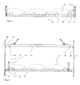
- Figure 1 depicts a typical known collapsible container 50 of some 12.19m (405ft) length or span, with a platform base deck 10 surmounted at each end by a pair of opposed corner posts 12.
- each corner post 12 is a top capture and handling fitting 13, such as a hollow rectangular box with apertures on three outermost sides for a standard so-called 'twistlock'.
- a bottom capture and handling fitting 15 is located at each four bottom corners of flat rack 50.
- Figure 1 depicts three small cars 16 disposed in tandem upon base deck platform 10 of flat rack 50.
- Figure 2 depicts a flat rack 18 similar to flat rack 50, but with base deck stub extensions 17 at each end - taking overall length typically to some 13.72m (45ft) or more.
- support posts 46 remain at a 12.19m (405ft) span.
- a crane lift spreader 19 Suspended above flat rack 18 is a crane lift spreader 19 with capture and handling fittings (such as twistlocks) 20 - to engage top apertures 14 of top fittings 13 for capture and lift of flat rack 18.
- capture and handling fittings such as twistlocks
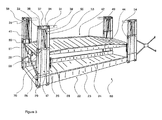
- Figure 3 shows a perspective view of an embodiment of the present invention, with multiple decks and dual (12.19m (405ft) and 13.72m (45ft)) span capture and handling fittings upon respective paired support posts, configured as collapse fold corner modules 70.
- a base 22 is configured as a shallow tray of longitudinal upstanding side rails 23 at each side of an intervening braced platform deck floor 24 of corrugated sheet steel.
- Inboard (bottom) support posts 25 are located at a 12.19m (405ft) span position and adjacent outboard (bottom) posts 26 at a 13.72m (45ft) span position.
- Bottom posts 25 and 26 are joined structurally by bridge plates 47, to create an integrated corner post module 70 surmounting base 22.
- Bottom posts 25 and 26 are pivotally mounted upon base 22 by hinges 29 fitted to side rails 23, along with paired torsion bar bias springs**, as detailed in Figures 8 and 10.
- Bottom posts 25, 26 are configured as hollow (rectangular or circular) box sections, from which telescope respective inboard and outboard upper posts 55, 56 to carry a movable upper deck 42.
- Upper posts 55, 56 are capped by respective capture and handling top fittings 31, 33.
- a top rail 37 joins fittings 31, 33 and is extended inward by a (spreader impact) guard bar 38.
- Paired (or single) end access gates 28 are mounted by hinges 39 upon outboard bottom posts 26 at opposite deck ends.
- Hinges 30 allow gates 28 to rotate through 270 degrees, from a closed position abutting one another or an opposite post 26, to a folded back open position (not illustrated) alongside base 22.
- base deck 24 is a movable upper deck 42 of upstanding longitudinal side rails 49 at opposed sides of braced platform deck floor 43, also of corrugated sheet steel.
- Upper deck 42 is suspended from wire cable or chains 41 detachably connected by removable pins 51 to side rails 49 - cable 41 passing over pulley wheels 39 mounted upon inboard upper posts 55.
- Pulleys 39 are disposed close to post 55 and top fitting 31 axis, to bring cable 41 close to, or within the confines of, corner support post module 70.
- a travel limit stop 54 is fitted to one or both bottom posts 25, 26, for upper deck 42 support when cables 41 are released to allow upper post 55, 56 extension to present capture fittings 31, 33 above an upper deck load 26, as depicted in Figure 6.
- Limit stop 54 represents a lower limit for upper deck 42 when cargo is carried upon base deck 22, but is disengaged to allow upper deck 42 to be lowered upon base deck 22 in a single deck operating mode or preparatory to overall flat rack collapse.
- a removable detent 58 is operable to lock together associated bottom and upper posts 25/55, 26 / 56.
- Figures 4 and 5 show upper support post 55, 56 extension, initially to carry upper deck 42 and then beyond an upper deck load 66.
- upper deck 42 along with its car load 66, can be carried way above base deck 22.
- upper deck 42 can be lowered closer to base deck 22, as depicted in Figure 5.
- the roofs of tall vehicles 65 on base deck 22 can intrude somewhat into the under-deck confines of upper deck 42, allowing a closely inter-nested compact load profile.
- Upper deck 42 can be restrained by locks 64, with and cables 41 uncoupled by releasing pins 51.
- container 60 can be handled by a spreader (not shown) or support a corresponding container stacked upon it.
- inter-post detents 58 are engaged between upper posts 55, 56 and respective bottom posts 25, 26, as a default load carrying stop, upon failure of support wire 41 or lift ram 35 collapse.
- upper support posts 55, 56 are locked to respective bottom posts 25, 26 by detents 58, shot through corresponding aligned holes therein.
- Detents 58 take lifting, racking and stacking loads placed upon capture fittings 31 or 33.
- Inter-post detents 58 are desirably configured as flat-faced latch pins, for load spread and to minimise wear or risk of seizure in situ.
- Hydraulic lift rams 35 are located between inboard and outboard bottom support posts 25, 26.
- Extendible ram pistons 36 lie between upper inboard and outboard support posts 55, 56 and are secured to bar 37 by a capture pin 34.
- Lift rams 35 sit upon a base frame 45 within corner module 70 and operate selectively - say through a hand pump - upon bar 37 through capture pin 34
- Ram 36 retraction or extension moves upper posts 55, 56 and associated pulley 39, which effectively lengthens or shortens the run of cable 41 by double the ram 36 'throw' for rapid deck movement.
- Upper and base decks 42, 22 are of complementary 'U'-shaped cross-sectional profile for a certain interfit.
- upper deck 42 can sit or nest within 'U' tray profile confines of base deck 22 - as depicted in broken line in the fragmentary end view of Figure 10.
- Guard bar 38 inhibits contact of, say, a laterally misaligned 12.19m (405ft) spreader with upper deck load 66.
- a post hinge 29, has a pivot pin 27 axis of horizontal longitudinal orientation, so bottom posts 25 and 26 can fold transversely together towards base deck 24.
- Figure 6 shows differential relative height of hinges 29 for bottom posts 25, 26 at opposite deck sides.
- single or multiple end gates 28 are locked together and/or to an opposite post by a spigot 52.
- These stub posts 67 are subjected to severe racking and stacking loads and are braced by the interlocked post, gate and deck structure.
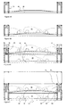
- Figure 7 depicts end gate(s) 28 swung open through 180 degrees, allowing end access for cargo onto floor 24 of base 22.
- Deck floor 44 of upper deck 42 is shown in a raised position, allowing a car 65 to drive in and out underneath any cars 66 upon floor 23.
- Figure 8 shows a corresponding end elevation to Figures 6 and 7, but with upper corner support post extensions 55, 56 retracted into respective bottom corner support posts 25, 26.
- End gate 28 is folded back through 270°, to lie alongside longitudinal sides of flat rack 60.
- Upper deck 42 has been lowered and its floor surface 44 lies upon base deck floor 24.
- posts 25 and 26 are counter folded inward - respectively from left and then from the right as viewed - as indicated by arrows A and B towards floor 24 about pivot pins 27.
- Guard bar 38 and top rail 37 can fold easily with the corner posts 25, 26 and one or more end gates 28 can fold along therewith to lie unobtrusively within a compact overall collapse folded module 60 profile.
- a bottom support post for a single end gate 28 is folded first, so gate 28 sits underneath both its appended post and an overlying post
- a ramp end profile base deck 24 allows bottom post 25, 25 fold within the depth of base side rails 23.
- Capture fittings 31,33 for 13.72m (45ft) and 12.19m (405ft) span could be (re-) located along top rail 37 or guard bar 38.
- Figure 8 is an end elevation of a stack 80 of some five flat-pack collapsed flat racks 60, with respective support posts 25 and 26 folded inward as described.
- Overall stack 80 depth generally equates to that of an erected individual flat rack 60, with top posts 55, 56 retracted within respective bottom posts 25, 26.
- Flat racks 60 can be inter-coupled through respective adjoining capture fittings 68 to create a unitary stack assembly 80, which can be handled from uppermost top fittings 68.
- Figure 10 is an enlarged fragmentary side elevation detail of a corner support post module at one end of flat rack 60.
- Corner posts 25, 26 are erected and locked in place with one or more end gates 28 locked together, or to opposite posts from which they are hinged.
- Posts 55, 56 are raised, along with top rail 37, capture fittings 31, 33 and guard rail 38 from a fully retracted position shown in broken line 37 '.
- Pump driven hydraulic ram 35 moves posts 55, 56 up and down within posts 25, 26.
- a ram piston rod 36 acts through a pin 34 upon top rail 37 to push up top rail 37 and raise upper structure 60 (of elements 55,56, 37 and 38).
- posts 55,56 can be locked in place by detent 58 operative on axis 48.
- detent 58 is withdrawn so gravity action retracts ram piston 36, and/or by exhaust pumping of ram 35 cylinder.
- Raising and lowering of upper support posts 55, 56 has an additional function.
- a pulley wheel 39 is mounted upon bar 37 by a bracket 49.
- a chain or wire rope 41 Over the pulley 39 is draped a chain or wire rope 41, pinned at one end ** to upper deck 42, and at the other end is secured to post 25 by a pin 63.
- deck 42 can be pinned in place by a deck lock 64 upon post 25 - and upon which deck 42 can rest solidly for transport.
- movable upper deck 42 has a platform infill at the top edge of side rails 43 - affording greater headspace to an underlying cargo on base deck 22.
- upper deck floor 24 might be replaced, partially or overall, by spaced transverse bars 61, locally to capture and support individual car 66 wheels.
- bars 61 might be adjustable, to allow selective local tilt of cars 66 when upper deck 42 is raised clear of base 22.
- upper deck 42 could be raised and lowered by external or auxiliary means - such as a crane, fork truck or some other specially adapted device.
- Base deck 22 and indeed also movable upper deck 42 could be of adjustable (eg telescopic) span.
- a 13.72m (45ft) flat rack could be extended or retracted to some other length.
- Upper deck 42 could be raised to a high level, as a protective cover or roof over lower deck cargo.
- End gate(s) 28 could be wholly or partially infilled or panelled, for cargo protection.
- One end of deck 42 could be raised before the other, and vehicles 26 driven up the slope - requiring less lifting work by rams 35.
- Base and upper decks 22, 42 can act together when nested and even locked together as an integrated structure to support larger heavier vehicles or cargo.
- Vehicles wider than (erect) post 15, 16 spacing can be driven between, by canting them out beyond the vertical erect position illustrated.
- posts could be folded outward , say to a horizontal position, for an access width greater than the internal width of base 14.
- Deck 42 can be removable.
- Deck floors 24, 44 can be of multiple discrete (albeit possibly edge interlinked) elements, for individual relative local slope adjustment, more readily to accommodate different car shapes and sizes.
- the cable transfer pulley is desirably fitted at or close to the piston ram axis centre line.
- the post base pivot is also desirably fitted at or close to the post axis or centre-line.
- Taller or more upright stance vehicles such as so-called people carriers or multi-purpose vehicles (MPV's) have a somewhat tapered profile, from a taller rear (tailgate) end to a shallower front bonnet.
- MPV's multi-purpose vehicles
- Load height or head space between decks when in their transit position is generally of even depth - and so may be inadequate for taller vehicles or inefficiently occupied by such a multiple load profile.
- the Applicant's earlier Multi-Deck PCT/GB97102319 envisaged multiple decks with relative deck portion and attendant load tilt and re-orientation, for denser inter-nesting load packing.
- Ramp ends of a deck allow end vehicles to sit with one set of (rear) wheels somewhat lower.
- a deck trap door (such as 69 in Figure 13 upper deck), could be fitted - to allow wheels at a taller (rear) vehicle end to sit lower in the deck and bring the roof contour into greater conformity with available load height.
Landscapes
- Engineering & Computer Science (AREA)
- Mechanical Engineering (AREA)
- Auxiliary Methods And Devices For Loading And Unloading (AREA)
- Body Structure For Vehicles (AREA)
- Load-Engaging Elements For Cranes (AREA)
- Tents Or Canopies (AREA)
- Power Steering Mechanism (AREA)
- Audible-Bandwidth Dynamoelectric Transducers Other Than Pickups (AREA)
- Leg Units, Guards, And Driving Tracks Of Cranes (AREA)
Abstract
Description
- Collapsible platform deck, or so-called 'flat rack', containers adapted for carrying (road) vehicles, in particular cars, are known.
- Thus for example, the Applicant's
WO-A-0069677 - Typically the flat rack is some 12.19m (405ft) long, with a deck capacity for 2 or 3 cars in tandem.
- Recent developments in containers have allowed an increase in standardised length from 12.19m (405ft) to 13.72m (45ft) - and in some countries even longer at 58ft.
- Handling devices and transport vehicles for the former 12.19m (405ft) standard containers have hitherto been adapted to carry only 12.19m (405ft) lengths.
- Nowadays, longer 13.72m (45ft) length spreaders for top lifting and 13.72m (45ft) span cargo hold cell guides are increasingly common in containerised sea going cargo vessels or ships, for constraining and guiding 13.72m (45ft) containers.
- For compatibility between 12.19m (405ft) and 13.72m (45ft) containers, supplementary capture and handling points, (such as twistlocks upon corner posts), are required at 12.19m (405ft) positions on 13.72m (45ft) long containers.
- This allows 12.19m (405ft) spreaders, and perhaps 12.19m (405ft) trailers or rail wagons, to engage capture fittings at 12.19m (405ft) positions, even though the container extends each end by another 2 ft.
- However, a problem arises in using 12.19m (405ft) spreaders to handle 13-72m (45ft) containers within 13.72m (45ft) span cell guides.
- Once within a ship, a 13.72m (45ft) container slides down 13.72m (45ft) span cell guides, rubbing its corner fittings upon cell guide surfaces.
- In this way a 13.72m (45ft) container can be lowered safely and rapidly down into a vessel in accurate registration with - and to sit with its handling and support fittings upon - those of an underlying 13.72m (45ft) container.
- For so long as a 12.19m (405ft) span spreader remains attached to a 13.72m (45ft) container, accuracy of lateral and longitudinal location is ensured within cell guides.
- Once detached from a container, a 12.19m (405ft) spreader can be raised up a cell guide,albeit is no longer governed by cell guide to container contact.
- However, the spreader is moving away from exposed cargo on the deck of the container just deposited.
- For container pick up, a crane must negotiate the spreader carefully down between cell guides and accurately register respective 12.19m (405ft) capture fittings.
- In doing so, the spreader and cargo can come into inadvertent contact, with attendant damage risk.
- This is less of a concern for solid roof (eg dry freight) containers, since if capture fittings should fail to register and engage, the roof deflects and supports the spreader and protects the cargo inside.
- An open frame flat rack has no roof, so a 12.19m (405ft) spreader travelling down between cell guides and missing top corner fittings can easily impact exposed cargo.
- Some form of cargo protection is thus desirable for a flat rack.
- One protection option would be to insist that 13.72m (45ft) spreaders be used in cell guide operation, and indeed this is virtually the norm.
- A 13.72m (45ft) spreader could readily pass down cell guides and locate directly into 13.72m (45ft) capture fittings, such as those located upon corner posts - and safely pick up the flat rack without cargo damage.
- However, 12.19m (405ft) spreaders are still in use - even on 13.72m (45ft) cell guide vessels.
- For compatibility with existing container fleets, capture and handling fittings at 12.19m (405ft) positions must be provided - as land based operations (where there are no cell guides) still use 12.19m (405ft) spreaders.
- According to one aspect of the invention, a flat rack has capture and handling fittings, such as upon corner posts, at different handling spans.
- A prime example would be capture and handling fittings at both 13.72m (45ft) and 12.19m (405ft) standard positions.
- This allows dual mode handling operation.
- Capture and handling fittings could be upon respective support posts or share a post.
- Multiple posts could be grouped in post modules with common extension drives, such as hydraulic rams and/or cables.
- Flat racks are generally collapsible, so that when cargo is unloaded from a platform base, end frames and corner posts can be folded down thereupon, in a collapsed compact 'flat - pacK' (return-empty) configuration.
- Such collapsed units can be stacked, one upon another, for economical storage and transport.
- The container stack shares the footprint of an individual container and stack depth can be contrived to match container depth standards.
- Thus, when coupled together (say through their respective capture fittings), the stack contents can be handled together as a unified load.
- If corner posts are required at 12.19m (405ft) and 13.72m (45ft) positions a total of 8 corner posts surmount a common platform deck and all of which be folded down - perhaps one on top of the other - adding to folded stack height.
- According to another aspect of the invention, a flat rack has handling capture fittings upon corner posts, at different capture and handling spans, such as at both 12.19m (405ft) and 13.72m (45ft) standard positions, all configured for compact collapse fold upon a base deck, or inter-nested multiple deck platforms.
- In a particular construction, a flat rack has at one or both ends of a rectangular base a multiple (two or more) post structure, each with respective capture and handling fittings at is upper end, for multiple alternative container handling spans.
- Support posts at opposite sides could be pivot mounted for inward transverse fold, to overlie one another upon a platform deck.
- Support post pivots at different heights, would allow mutual collapse fold overlay.
- Support post pivot mountings could be biased by torsion bar springs, to counterbalance post weight.
- On-board hydraulic rams, and cable pulley drive coupling, could effect support post extension and suspended deck movement.
- Paired telescopic support posts, could be operable by joint ram and cable drive, with respective capture and handling fittings at different standard spans
- A movable deck, could be carried at or adjacent each corner, by paired adjustable span support posts, with respective capture and handling fittings at different spans.
- A movable upper deck could be carried by support posts surmounting a base deck.
- An end access closure gate could be fitted between paired support posts,with respective capture and handling fittings at opposite sides of each deck end.
- A tapered deck end profile could create end ramps for a vehicle cargo, to allow vehicle tilt for compact fit within flat rack deck confines.
- Similarly, a hinged trap door in a deck floor intermediate deck ends could allow local tilt of a vehicle cargo disposed with wheels thereupon.
- Multiple capture and handling fittings could be carried by individual support posts.
- A support post extension ram could be disposed within post confines.
- Similarly, a cable suspension could be disposed within support post confines.
- Dual inter-fitting decks could be carried between adjustable span support posts, pivotally mounted for inward transverse fold, to allow a compact overall collapse fold with support posts within mutually inset decks.
- A selectively operable deck lock could secure deck position.
- A selectively operable collapse fold, interlock could be fitted between inward folded support posts, gate carried thereby, and underlying deck.
- A collapse fold support post and underlying deck interaction could brace residual corner stub posts and attendant capture and handling fittings.
- A movable deck over-travel facility, could facilitate under deck loading.
- A movable deck over-travel lock could secure under deck loading access.
- There now follows a description of some particular embodiments of the invention, by way of example only, with reference to the accompanying diagrammatic and schematic drawings.
- Various features identified can be 'mixed and matched' selectively - albeit it is impractical here to set out every feasible combination.
- Figure 1 shows a side elevation of a known single (base) platform deck or flat rack of some 12.19m (405ft) span, with triple tandem vehicle (car) load;
- Figure 2 shows an extended variant of the flat rack of Figure 1 extended to some 13.72m (45ft) span, for location in a containerised cargo vessel cell guides, along with a spreader beam of 12.19m (405ft) span;
- Figure 3 shows a perspective view of a collapsible multiple (dual) deck flat rack adapted for vehicle load according to the invention and with both 12.19m (405ft) and 13.72m (45ft) capture and handling fittings;
- Figures 4A through 4C show sequential loading operation for the dual deck flat rack of Figure 3;
- Figure 4A shows a movable upper deck lowered upon a base deck between erect corner support post modules ;
- Figure 4B shows initial car cargo loading of the lowered upper deck;
- Figure 4C shows elevation of the upper deck to allow base deck loading and optional support post extension to present capture and handling fittings above upper deck load height;
- Figure 5 shows a fully loaded flat rack of Figure 4C with end support post modules extended to support an overlying container;
- Figures 6 and 7 show an end elevations of the flat rack of Figures 3, 4 and 5, with a single full-width end gate hung from one corner post closed; double half-span gates hung from respective posts may be substituted;
- Figure 6 shows a single gate swung open for unobstructed deck end access;
- Figure 7 shows gate closed and coupled between opposite end posts as end bracing;
- Figure 8 shows an end elevation of transverse inward (mutually overlaid) fold of dual (12.19m (405ft) and 13.72m (45ft)) span corner support post modules at one deck end;
- Figure 9 shows an end elevation a stack of collapsed flat racks of Figures 3, 4 and 5;
- Figure 10 shows a detail of a dual (12.19m (405ft) and 13.72m (45ft)) span corner end post module, with hydraulic ram and cable pulley lift, for the flat rack of Figures 3, 4 and 5;
- Figures 11 through 14 show views of an engineered flat rack embodying features of preceding drawings;
- Figure 11 shows a 3D perspective view of a dual deck flat rack, with movable upper deck carried by corner support post modules (with 12.19m (405ft) and 13.72m (45ft) span capture and handling fittings), surmounting a base deck and mounted for inward compact Collapse fold;
- Figure 12 shows a side elevation of the flat rack of Figure 11, with upper deck elevated from a cable suspension with pulley traveller upon extendible rams in corner post modules;
- Figure 13 shows a plan view of the flat rack of Figures 11 and 12; and
- Figure 14 shows an end elevation of the flat rack of Figures 11 through 13, with single hinged end gate addressing both upper and base deck access;
- Referring to the drawings ...
- Figure 1 depicts a typical known
collapsible container 50 of some 12.19m (405ft) length or span, with aplatform base deck 10 surmounted at each end by a pair of opposed corner posts 12. - Upon each
corner post 12 is a top capture and handling fitting 13, such as a hollow rectangular box with apertures on three outermost sides for a standard so-called 'twistlock'. - Similarly, a bottom capture and handling fitting 15 is located at each four bottom corners of
flat rack 50. - Figure 1 depicts three
small cars 16 disposed in tandem uponbase deck platform 10 offlat rack 50. - Overall
flat rack 50 height (distance oftop fitting 13 above ground) is limited by fixed end support post frames 46. - Figure 2 depicts a
flat rack 18 similar toflat rack 50, but with basedeck stub extensions 17 at each end - taking overall length typically to some 13.72m (45ft) or more. - However, support posts 46 remain at a 12.19m (405ft) span.
- Suspended above
flat rack 18 is acrane lift spreader 19 with capture and handling fittings (such as twistlocks) 20 - to engagetop apertures 14 oftop fittings 13 for capture and lift offlat rack 18. - Should a capture fitting 20 not line up with
top aperture 14 oftop fitting 13, but sit over to one side, as denoted by19' and with capture fitting at 20' , serious contact damage could occur tocar 16 roof. - When a 13.72m (45ft) span
flat rack 18 is located in corresponding 13.72m (45ft) span vessel cell guides 21, its lateral and longitudinal position is constrained. - However, a 12.19m (405ft) span spreader19 lowered down inside 13.72m (45ft) span cell guides 21, can still swing from one side to the other, as denoted by broken line 19', and cause damage to a
car 16. - If
spreader 19 were made, say, 13.72m (45ft) span, as denoted bybroken line 19", and with twistlocks located at 20', 20 ", nocargo 16 damage could arise, asspreader 19" would also be constrained by cell guides 21. - Hitherto, neither spreaders nor containers have featured both 12.19m (405ft) and 13.72m (45ft)
span capture fittings 20. - Thus
cargo 16 offlat rack 18 is protected from 13.72m (45ft)spreader 19 contact, but not from a 12.19m (405ft)spreader 19. - Figure 3 shows a perspective view of an embodiment of the present invention, with multiple decks and dual (12.19m (405ft) and 13.72m (45ft)) span capture and handling fittings upon respective paired support posts, configured as collapse
fold corner modules 70. - More specifically, a
base 22 is configured as a shallow tray of longitudinal upstanding side rails 23 at each side of an intervening bracedplatform deck floor 24 of corrugated sheet steel. - Inboard (bottom) support posts 25 are located at a 12.19m (405ft) span position and adjacent outboard (bottom) posts 26 at a 13.72m (45ft) span position.
- Bottom posts 25 and 26 are joined structurally by
bridge plates 47, to create an integratedcorner post module 70 surmountingbase 22. - Bottom posts 25 and 26 are pivotally mounted upon
base 22 byhinges 29 fitted to side rails 23, along with paired torsion bar bias springs**, as detailed in Figures 8 and 10. - Bottom posts 25, 26 are configured as hollow (rectangular or circular) box sections, from which telescope respective inboard and outboard
upper posts upper deck 42. -
Upper posts top fittings - A
top rail 37 joinsfittings guard bar 38. - Paired (or single)
end access gates 28 are mounted byhinges 39 upon outboard bottom posts 26 at opposite deck ends. -
Hinges 30 allowgates 28 to rotate through 270 degrees, from a closed position abutting one another or anopposite post 26, to a folded back open position (not illustrated) alongsidebase 22. - Above
base deck 24 is a movableupper deck 42 of upstanding longitudinal side rails 49 at opposed sides of bracedplatform deck floor 43, also of corrugated sheet steel. -
Upper deck 42 is suspended from wire cable orchains 41 detachably connected byremovable pins 51 to side rails 49 -cable 41 passing overpulley wheels 39 mounted upon inboardupper posts 55. -
Pulleys 39 are disposed close to post 55 and top fitting 31 axis, to bringcable 41 close to, or within the confines of, cornersupport post module 70. - As more readily discerned from Figure 10, the other end of
cable 41 is secured to inboardbottom post 25 atanchor pin 53. - A
travel limit stop 54 is fitted to one or bothbottom posts upper deck 42 support whencables 41 are released to allowupper post capture fittings upper deck load 26, as depicted in Figure 6. -
Limit stop 54 represents a lower limit forupper deck 42 when cargo is carried uponbase deck 22, but is disengaged to allowupper deck 42 to be lowered uponbase deck 22 in a single deck operating mode or preparatory to overall flat rack collapse. - A
removable detent 58 is operable to lock together associated bottom andupper posts 25/55, 26 / 56. - Figures 4 and 5 show
upper support post upper deck 42 and then beyond anupper deck load 66. - Operationally, absent any transverse header beams or braces,
upper deck 42, along with itscar load 66, can be carried way abovebase deck 22. - This provides ample drive-on/off headroom for a base
deck car load 65. - Once both
decks upper deck 42 can be lowered closer tobase deck 22, as depicted in Figure 5. - In this mode, the roofs of
tall vehicles 65 onbase deck 22 can intrude somewhat into the under-deck confines ofupper deck 42, allowing a closely inter-nested compact load profile. -
Upper deck 42 can be restrained bylocks 64, with andcables 41 uncoupled by releasingpins 51. - This allows full
upper post capture fittings deck car load 66. - In this
mode container 60 can be handled by a spreader (not shown) or support a corresponding container stacked upon it. - For security,
inter-post detents 58 are engaged betweenupper posts support wire 41 or liftram 35 collapse. - Once raised to a desired position, upper support posts 55, 56 are locked to respective bottom posts 25, 26 by
detents 58, shot through corresponding aligned holes therein. -
Detents 58 take lifting, racking and stacking loads placed uponcapture fittings -
Inter-post detents 58 are desirably configured as flat-faced latch pins, for load spread and to minimise wear or risk of seizure in situ. - Hydraulic lift rams 35 are located between inboard and outboard bottom support posts 25, 26.
-
Extendible ram pistons 36 lie between upper inboard and outboard support posts 55, 56 and are secured to bar 37 by acapture pin 34. - Lift rams 35 sit upon a base frame 45 within
corner module 70 and operate selectively - say through a hand pump - uponbar 37 throughcapture pin 34 -
Ram 36 retraction or extension movesupper posts pulley 39, which effectively lengthens or shortens the run ofcable 41 by double the ram 36 'throw' for rapid deck movement. - Upper and
base decks - Thus, when fully lowered by
cables 41 and retraction of lift rams 35,upper deck 42 can sit or nest within 'U' tray profile confines of base deck 22 - as depicted in broken line in the fragmentary end view of Figure 10. -
Guard bar 38 inhibits contact of, say, a laterally misaligned 12.19m (405ft) spreader withupper deck load 66. - Thus either a 12.19m (405ft) or 45 spreader can be used without risk of load damage - unlike, say, the
flat rack 18 of Figure 2. - A
post hinge 29, has apivot pin 27 axis of horizontal longitudinal orientation, sobottom posts base deck 24. - Figure 6 shows differential relative height of
hinges 29 forbottom posts - This allows collapsed
posts base deck 22 confines when folded transversely inward. - In order to keep
support posts multiple end gates 28 are locked together and/or to an opposite post by aspigot 52. - When post and gate are fully collapse folded inward, they are secured to an
underlying base deck 24 by a lock 57 - creating a stiff braced structure. - Residual upstanding stub posts 67, with respective top capture and
handling fittings 68, protrude beyond the transverse inward folded support posts 25, 26. - This allows mutual stacking - as represented in Figure 9 - without contact damage to internal fittings.
- These stub posts 67 are subjected to severe racking and stacking loads and are braced by the interlocked post, gate and deck structure.
- Figure 7 depicts end gate(s) 28 swung open through 180 degrees, allowing end access for cargo onto
floor 24 ofbase 22. -
Deck floor 44 ofupper deck 42 is shown in a raised position, allowing acar 65 to drive in and out underneath anycars 66 uponfloor 23. - Figure 8 shows a corresponding end elevation to Figures 6 and 7, but with upper corner
support post extensions -
End gate 28 is folded back through 270°, to lie alongside longitudinal sides offlat rack 60. -
Upper deck 42 has been lowered and itsfloor surface 44 lies uponbase deck floor 24. - In order to collapse
flat rack 22, posts 25 and 26 are counter folded inward - respectively from left and then from the right as viewed - as indicated by arrows A and B towardsfloor 24 about pivot pins 27. -
Guard bar 38 andtop rail 37 can fold easily with the corner posts 25, 26 and one ormore end gates 28 can fold along therewith to lie unobtrusively within a compact overall collapse foldedmodule 60 profile. - A bottom support post for a
single end gate 28 is folded first, sogate 28 sits underneath both its appended post and an overlying post - A ramp end
profile base deck 24 allowsbottom post - It is envisaged that
discrete posts 25/ 55, 26 / 56 might be integrated as a single post. -
Capture fittings top rail 37 orguard bar 38. - Figure 8 is an end elevation of a
stack 80 of some five flat-pack collapsedflat racks 60, with respective support posts 25 and 26 folded inward as described. -
Overall stack 80 depth generally equates to that of an erected individualflat rack 60, withtop posts -
Flat racks 60 can be inter-coupled through respective adjoiningcapture fittings 68 to create aunitary stack assembly 80, which can be handled from uppermosttop fittings 68. - Figure 10 is an enlarged fragmentary side elevation detail of a corner support post module at one end of
flat rack 60. - Corner posts 25, 26 are erected and locked in place with one or
more end gates 28 locked together, or to opposite posts from which they are hinged. -
Posts top rail 37,capture fittings guard rail 38 from a fully retracted position shown in broken line 37 '. - Pump driven
hydraulic ram 35 moves posts 55, 56 up and down withinposts - A
ram piston rod 36 acts through apin 34 upontop rail 37 to push uptop rail 37 and raise upper structure 60 (ofelements - Once raised to a desired height, posts 55,56 can be locked in place by
detent 58 operative onaxis 48. - For retraction of upper support posts 55, 56,
detent 58 is withdrawn so gravity action retractsram piston 36, and/or by exhaust pumping ofram 35 cylinder. - Raising and lowering of upper support posts 55, 56 has an additional function.
- A
pulley wheel 39 is mounted uponbar 37 by abracket 49. - Over the
pulley 39 is draped a chain orwire rope 41, pinned at one end ** toupper deck 42, and at the other end is secured to post 25 by a pin 63. - As upper support posts 55, 56 are raised up and down by
ram 35, sowire 41 transfers the motion toupper deck 42 , from a lowermost position 42 ' nested withinbase 22 up to a desiredheight 42". - Once at desired height,
deck 42 can be pinned in place by adeck lock 64 upon post 25 - and upon whichdeck 42 can rest solidly for transport. - Although the
flat rack 60 described has telescopic corner support posts 55,56, fixed height corner support posts are also envisaged. - Other embodiments might include a profiled
deck 24 surface to maximise slope ofcars 66 placed upon it. - In this case, movable
upper deck 42 has a platform infill at the top edge of side rails 43 - affording greater headspace to an underlying cargo onbase deck 22. - As depicted in Figure 5,
upper deck floor 24 might be replaced, partially or overall, by spaced transverse bars 61, locally to capture and supportindividual car 66 wheels. - Rather than being fixed to
deck 22, bars 61 might be adjustable, to allow selective local tilt ofcars 66 whenupper deck 42 is raised clear ofbase 22. - Built-in
rams 35 orpulley wheels 39 and cables orchains 41 are not essential. - Rather,
upper deck 42 could be raised and lowered by external or auxiliary means - such as a crane, fork truck or some other specially adapted device. -
Base deck 22 and indeed also movableupper deck 42 could be of adjustable (eg telescopic) span. - Thus, say, a 13.72m (45ft) flat rack could be extended or retracted to some other length.
- Whilst 12.19m (405ft) and 13.72m (45ft) lengths are widely adopted standards,others can be accommodated.
-
Upper deck 42 could be raised to a high level, as a protective cover or roof over lower deck cargo. - End gate(s) 28 could be wholly or partially infilled or panelled, for cargo protection.
- Side curtains could hang from
guard bars 38 betweenposts 55, and connected to bottom side rails 23, for an enclosed cargo space. - One end of
deck 42 could be raised before the other, andvehicles 26 driven up the slope - requiring less lifting work by rams 35. - Base and
upper decks - Vehicles wider than (erect)
post - Indeed posts could be folded outward , say to a horizontal position, for an access width greater than the internal width of
base 14. -
Deck 42 can be removable. -
Deck floors - Alternatives of deck end ramps and intermediate trap doors are discussed later.
- The cable transfer pulley is desirably fitted at or close to the piston ram axis centre line.
- The post base pivot is also desirably fitted at or close to the post axis or centre-line.
- Taller or more upright stance vehicles, such as so-called people carriers or multi-purpose vehicles (MPV's) have a somewhat tapered profile, from a taller rear (tailgate) end to a shallower front bonnet.
- Load height or head space between decks when in their transit position is generally of even depth - and so may be inadequate for taller vehicles or inefficiently occupied by such a multiple load profile.
- The Applicant's earlier Multi-Deck
PCT/GB97102319 - Ramp ends of a deck allow end vehicles to sit with one set of (rear) wheels somewhat lower.
- This would require end vehicles to be loaded front first from respective ends, for with decks fully separated to be reversed on from one end.
- Similarly, a deck trap door, (such as 69 in Figure 13 upper deck), could be fitted - to allow wheels at a taller (rear) vehicle end to sit lower in the deck and bring the roof contour into greater conformity with available load height.
- This includes vertical between deck load space.
-
- 10
- platform base
- 12
- corner posts
- 13
- top capture + handling fitting
- 14
- top apertures
- 15
- bottom capture fitting
- 16
- car cargo load
- 18
- flat rack
- 19, 19'
- crane lift spreader
- 20, 20'
- capture fitting (spreader 19)
- 21
- cell guides
- 22
- base
- 23
- longitudinal side rails
- 24
- platform deck floor
- 25
- (inboard) bottom support post
- 26
- (outboard) bottom support post
- 27
- pivot pin
- 28
- end gate
- 29
- post hinge
- 30
- gate hinge
- 31
- top capture and handling fitting
- 33
- top capture and handling fitting
- 34
- capture pin
- 35
- lift ram
- 36
- ram piston
- 37
- bar
- 38
- guard bar
- 39
- pulley
- 41
- wire cable /chain
- 42, 42'
- (movable) upper deck (+ 42")
- 43
- side rail
- 44
- deck
- 45
- ram frame
- 46
- corner support post end frames
- 47
- bridge plate
- 48
- detent (58) axis
- 49
- pulley bracket
- 50
- flat rack
- 51
- removable cable pin
- 52
- gate spigot lock
- 53
- cable anchor pin
- 54
- travel limit stop
- 55
- (inboard) upper post
- 56
- (outboard) upper post
- 57
- gate-post-deck lock
- 58
- inter-post detent
- 59
- bias springs
- 60
- flat rack
- 61
- deck bars
- 62
- bar position
- 64
- (upper) deck lock
- 65
- (lower deck) car load
- 66
- (upper deck) car load
- 67
- stub post
- 68
- capture + handling fitting
- 69
- (deck) trap door
- 70
- corner support post module
- 80
- stack
Claims (25)
- A platform deck or flat rack container (50), with capture and handling fittings (31,33), disposed at different spans,
- A flat rack of Claim 1, with capture and handling fittings (31,33) grouped by different span standards.
- A flat rack of either preceding claim, with respective support posts (25,26,55,56), and attendant capture and handling fittings(31,33), at different spans.
- A flat rack of any preceding claim, with multiple support posts, grouped together in a post module at or adjacent deck ends.
- A flat rack of any preceding claim, with independently folding support post groups.
- A flat rack of any preceding claim, with capture and handling fittings (31,33) at both 12.19m (40ft) and 13.72m (45ft) span, for conformity with dual handling standards.
- A flat rack of any preceding claim, with support posts (25, 26, 55, 56) at opposite sides pivot mounted for inward transverse fold, to overlie one another upon a platform deck (42).
- A flat rack of any preceding claim, with support post pivots at different heights, to allow mutual collapse fold overlay.
- A flat rack of any preceding claim, with support post pivot mountings biased by torsion bar springs, to counterbalance post weight.
- A flat rack of any preceding claim, with on-board hydraulic rams (36), and cable pulley (39) drive coupling, for support post extension and suspended deck movement.
- A flat rack of any preceding claim, with paired telescopic support posts, operable by joint ram and cable drive, with respective capture and handling fittings at different standard spans
- A flat rack of any preceding claim, with a movable deck (42), carried at or adjacent each corner by paired adjustable span support posts (25,26,55,56) with respective capture and handling fittings (31,33) at different spans.
- A flat rack of any preceding claim, with a movable upper deck (42), carried by support posts surmounting a base deck (22).
- A flat rack of any preceding claim, with an end access closure gate (28) between paired support posts (25,26,55,56), with respective capture and handling fittings(31,33) at opposite sides of each deck end.
- A flat rack of any preceding claim, with a tapered deck end profile to create end ramps for a vehicle cargo to allow vehicle tilt for compact fit within flat rack deck confines.
- A flat rack of any preceding claim, with a hinged trap door (69) in a deck floor (24) intermediate deck ends to allow local tilt of a vehicle cargo disposed with wheels thereupon.
- A flat rack of any preceding claim, with multiple capture and handling fittings, carried by individual support posts.
- A flat rack of any preceding claim, with a support post extension ram (35) disposed within post confines.
- A flat rack of any preceding claim, with a cable suspension disposed within support post confines.
- A flat rack of any preceding claim, with dual inter-fitting decks carried between adjustable span support posts pivotally mounted for inward transverse fold to allow a compact overall collapse fold with support posts within mutually inset decks.
- A flat rack of any preceding claim, with a selectively operable deck lock.
- A flat rack of any preceding claim, with selectively operable collapse fold interlock, between inward folded support posts, gate carried thereby, and underlying deck.
- A flat rack of any preceding claim, with a collapse fold support post and underlying deck interaction, to brace residual corner stub posts and attendant capture and handling fittings.
- A flat rack of any preceding claim, with movable deck over-travel facility, to facilitate under deck loading.
- A flat rack of any preceding claim, with movable deck over-travel lock (54), for secure under deck loading access.
Applications Claiming Priority (3)
| Application Number | Priority Date | Filing Date | Title |
|---|---|---|---|
| GBGB0226012.3A GB0226012D0 (en) | 2002-11-07 | 2002-11-07 | A car carrying container |
| GB0226012 | 2002-11-07 | ||
| PCT/GB2003/004805 WO2004041679A1 (en) | 2002-11-07 | 2003-11-05 | Collapsible flat rack |
Publications (2)
| Publication Number | Publication Date |
|---|---|
| EP1567429A1 EP1567429A1 (en) | 2005-08-31 |
| EP1567429B1 true EP1567429B1 (en) | 2007-07-18 |
Family
ID=9947408
Family Applications (1)
| Application Number | Title | Priority Date | Filing Date |
|---|---|---|---|
| EP03810535A Expired - Lifetime EP1567429B1 (en) | 2002-11-07 | 2003-11-05 | Collapsible flat rack |
Country Status (9)
| Country | Link |
|---|---|
| US (2) | US20060104755A1 (en) |
| EP (1) | EP1567429B1 (en) |
| JP (1) | JP2006505460A (en) |
| CN (1) | CN100463817C (en) |
| AT (1) | ATE367329T1 (en) |
| AU (1) | AU2003276480A1 (en) |
| DE (1) | DE60315065T2 (en) |
| GB (1) | GB0226012D0 (en) |
| WO (1) | WO2004041679A1 (en) |
Families Citing this family (46)
| Publication number | Priority date | Publication date | Assignee | Title |
|---|---|---|---|---|
| GB0226012D0 (en) * | 2002-11-07 | 2002-12-18 | Clive Smith Martin | A car carrying container |
| CN100398415C (en) * | 2004-07-23 | 2008-07-02 | 中国国际海运集装箱(集团)股份有限公司 | Platform container for transporting large cylindrical goods |
| US8915684B2 (en) | 2005-09-27 | 2014-12-23 | Fontaine Trailer Company, Inc. | Cargo deck |
| US7544027B2 (en) * | 2007-04-28 | 2009-06-09 | James Barker | System and method for loading vehicles onto the cargo bed of a transporting vehicle |
| NL1034670C2 (en) * | 2007-11-12 | 2009-05-14 | Arie Van Donge B V | Flat container and method for transporting vehicles. |
| US8790062B2 (en) * | 2008-04-01 | 2014-07-29 | Mi-Jack Products, Inc. | Distribution system |
| DE102008029075B3 (en) * | 2008-06-10 | 2010-01-21 | WAP Wöhr Automatikparksysteme GmbH & Co KG | Park for motor vehicles |
| US20110073595A1 (en) * | 2009-09-30 | 2011-03-31 | Murray Crane | Collapsible freight container |
| US8342784B2 (en) * | 2010-09-29 | 2013-01-01 | Raildecks (2009), Inc. | Collapsible intermodal transport platform |
| US8714895B2 (en) | 2010-09-29 | 2014-05-06 | Raildecks (2009), Inc. | Collapsible intermodal transport platform |
| US9004832B1 (en) | 2012-05-14 | 2015-04-14 | Raildecks (2009), Inc. | Intermodal container |
| US9156607B2 (en) | 2012-11-09 | 2015-10-13 | Fontaine Engineered Products, Inc. | Collapsible intermodal flat rack |
| WO2014089664A1 (en) | 2012-12-12 | 2014-06-19 | Oceanex Inc. | Flat rack |
| NO335191B1 (en) * | 2012-12-19 | 2014-10-20 | Polotec As | Transfer station for vehicles |
| CN103072765B (en) * | 2013-01-28 | 2014-12-31 | 浙江双友物流器械股份有限公司 | Layering device used in container |
| TWI488798B (en) * | 2013-02-01 | 2015-06-21 | Ming Lurn Prec Machine Co Ltd | Vehicle lift transmission mechanism and vehicle lift comprising the same |
| USD713114S1 (en) | 2013-03-15 | 2014-09-09 | Oceanex Inc. | Flat rack |
| CN103274138B (en) * | 2013-05-28 | 2015-09-09 | 浙江双友物流器械股份有限公司 | A kind of for the decker in container |
| CN104648449A (en) * | 2013-11-18 | 2015-05-27 | 铜陵市大明玛钢有限责任公司 | Steel pipe carrying cart |
| CA2894724A1 (en) * | 2014-06-19 | 2015-12-19 | Innovative Trailer Design Technologies Inc. | Intermodal shipping container box |
| KR101556396B1 (en) * | 2014-07-04 | 2015-09-30 | 김규완 | Container for automobiles |
| US20160278516A1 (en) * | 2015-03-26 | 2016-09-29 | James Lawrence | Product shipping system |
| AU2015394641B2 (en) * | 2015-05-13 | 2019-02-14 | Metso Finland Oy | A flotation plant and its uses, a method of changing a flotation tank in a tank module and a method of changing a module |
| CN107672956B (en) | 2016-08-01 | 2020-09-04 | 南通中集特种运输设备制造有限公司 | Double foldable frame box |
| ES2594802B1 (en) * | 2016-08-23 | 2017-09-26 | J.S.V. Logistic, S.L. | OPEN CONTAINER WITH SWING COVER |
| US10035464B2 (en) | 2016-08-26 | 2018-07-31 | Toyota Motor Engineering & Manufacturing North America, Inc. | Multi-level rear storage systems and methods for vehicles |
| CN106329390B (en) * | 2016-11-02 | 2018-06-29 | 国网江苏省电力公司仪征市供电公司 | A kind of vehicle-mounted crossing frame |
| GB2555792A (en) * | 2016-11-08 | 2018-05-16 | Tiger Trailers Ltd | Lifting mechanism for a double-deck container for transportation of goods |
| AU2017404842B2 (en) * | 2017-03-21 | 2019-03-28 | Spectainer Pty Limited | A collapsible intermodal container and a collapsible intermodal container assembly |
| CN107381388A (en) * | 2017-09-01 | 2017-11-24 | 宁津县万发机械有限责任公司 | A kind of container modularization liftable cable reel |
| CN109987351B (en) * | 2017-12-29 | 2024-07-12 | 广东新会中集特种运输设备有限公司 | Folding Box |
| CN108035578A (en) * | 2018-01-09 | 2018-05-15 | 何照纯 | A kind of collapsible shared bicycle intelligent stereo garage |
| AU2018271285B2 (en) * | 2018-03-24 | 2022-08-04 | David CEROCCHI | Transport trailer |
| CN109110322B (en) * | 2018-09-14 | 2020-12-18 | 谢永琴 | Automatic charging management and control flat cabinet with protection assembly |
| WO2020178637A1 (en) * | 2019-03-04 | 2020-09-10 | Goodpack Ibc (Singapore) Pte, Ltd, | Cargo unit |
| BR112021022787A2 (en) | 2019-05-17 | 2022-02-15 | Goodpack Ibc Singapore Pte Ltd | shipping containers |
| IL267832B2 (en) * | 2019-07-03 | 2023-05-01 | Fridenson Logistics services Ltd | Train wagon car carrier adapted for forklift lifting |
| RU2743296C2 (en) * | 2019-08-09 | 2021-02-16 | Акционерное общество "Завод металлоконструкций" | Pallet for locating and fixating an automobile semi-trailer on a flat wagon |
| CN110589270B (en) * | 2019-08-29 | 2024-07-12 | 广东新会中集特种运输设备有限公司 | Platform container |
| CN111532583B (en) * | 2020-06-09 | 2024-11-01 | 浙江盘毂动力科技有限公司 | Independent suspension tool rack |
| CN114074789B (en) * | 2020-08-10 | 2025-01-28 | 中包物联网科技(天津)有限公司 | A universal engine intelligent circulation device and management system |
| WO2022096928A1 (en) | 2020-11-03 | 2022-05-12 | Goodpack Ibc (Singapore) Pte Ltd | Collapsible crate |
| DE102021205134A1 (en) | 2021-05-20 | 2022-11-24 | Psa Automobiles Sa | Transport vehicle and method of operation therefor |
| CN116118603B (en) * | 2023-04-17 | 2023-06-20 | 成都成飞航空产业发展有限责任公司 | Aircraft skin transfer system |
| AT527188A1 (en) | 2023-04-28 | 2024-11-15 | Jonathan Pieringer Peter | Container for attachment to a rail-bound container wagon |
| EP4455048A1 (en) * | 2023-04-28 | 2024-10-30 | Peter Jonathan Pieringer | Container for attachment to a rail-bound container transport vehicle |
Family Cites Families (37)
| Publication number | Priority date | Publication date | Assignee | Title |
|---|---|---|---|---|
| US2128376A (en) * | 1936-01-06 | 1938-08-30 | Worth Co | Car loading device |
| US2523271A (en) * | 1944-10-25 | 1950-09-26 | Bartel Arthur | Load supporting pallet |
| US3480174A (en) * | 1967-08-02 | 1969-11-25 | James B Sherwood | Assembly of freight containers and foundation frame for use therewith |
| US3801177A (en) * | 1971-06-04 | 1974-04-02 | Fmc Corp | Frameless shipping container |
| US3830381A (en) * | 1972-04-27 | 1974-08-20 | Sea Land Service | Truck and outsize cargo container |
| US3807581A (en) * | 1972-11-07 | 1974-04-30 | Pullman Inc | Pallet with adjustable height legs |
| US4049149A (en) * | 1975-11-24 | 1977-09-20 | William Brener | Freight container universal corner |
| US4116135A (en) * | 1976-11-01 | 1978-09-26 | Southern Pacific Transportation Company | Sliding screen closure for rail cars |
| US4151925A (en) * | 1978-03-27 | 1979-05-01 | Pullman Incorporated | Flatrack container |
| NO159785C (en) * | 1979-10-16 | 1989-02-08 | Peter Howe | ADDITIONAL LOADING DEVICE. |
| GB2112356B (en) * | 1981-12-23 | 1985-06-19 | Boughton T T Sons Ltd | Improvements in or relating to transport frames for vehicles |
| FR2577534A1 (en) * | 1985-02-14 | 1986-08-22 | Weidmann Pittet Sa | NON-REUSABLE, HIGH CAPACITY INTERMODAL PACKAGING |
| US4714169A (en) * | 1987-03-26 | 1987-12-22 | Chrysler Motors Corporation | Collapsible/expandable shipping rack |
| US4986705A (en) * | 1987-11-25 | 1991-01-22 | Eis Corporation | Stackable freight container for holding stacked chassis |
| US4913061A (en) * | 1988-09-27 | 1990-04-03 | Youngblood Bernard J | Auto rack side panel support system |
| US5253975A (en) * | 1989-12-21 | 1993-10-19 | Taiyo Seiki Iron Works Co., Ltd. | Car loading apparatus |
| CA2091824A1 (en) * | 1992-03-18 | 1993-09-19 | Martin Clive-Smith | Freight container |
| US5394956A (en) * | 1993-08-30 | 1995-03-07 | Hulse; James M. | Suspended tender box |
| US5730578A (en) * | 1995-02-15 | 1998-03-24 | Wabash National Corporation | Lifting mechanism for a deck system |
| FR2741034B1 (en) * | 1995-11-13 | 1998-01-02 | Lohr Ind | STRUCTURAL EQUIPMENT FOR A ROAD VEHICLE PROVIDING AN ADDITIONAL MOBILE FLOOR |
| US5688086A (en) * | 1996-02-16 | 1997-11-18 | Aluminum Company Of America | Standard corner fittings for aluminum container frames |
| DE19730165A1 (en) * | 1997-07-14 | 1999-01-21 | Juergen Dipl Ing Gloystein | Device for transporting vehicles, in particular passenger cars, vans or the like |
| GB2329630A (en) * | 1997-09-24 | 1999-03-31 | Clive Smith Martin | Side-loading multi-deck container |
| IL126467A0 (en) * | 1998-10-06 | 1999-08-17 | Mifned Ltd | Sea/land going container for vehicle |
| GB2345282B (en) * | 1998-12-30 | 2001-09-05 | Kim Jum Gyu | Variable height container for vessel |
| GB9911483D0 (en) * | 1999-05-17 | 1999-07-14 | Clive Smith Martin | Vehicle mounting in container |
| GB2353031B (en) * | 1999-05-12 | 2003-12-31 | Martin Clive-Smith | Container with adjustable configuration |
| US6866160B2 (en) * | 2000-01-21 | 2005-03-15 | Feng Wang | Folding structure for foldable container |
| WO2002028747A1 (en) * | 2000-10-03 | 2002-04-11 | Clive Smith Martin | Container extension module |
| GB0024214D0 (en) * | 2000-10-03 | 2000-11-15 | Clive Smith Martin | A frame to extend a container height |
| CN1248927C (en) * | 2001-02-09 | 2006-04-05 | 金点奎 | Height adjustable container for ship |
| US6533510B2 (en) * | 2001-07-23 | 2003-03-18 | International Transport Logistics, Inc. | Carrier for a trailer, system thereof using a stacking device, and method thereof |
| US6814529B2 (en) * | 2002-04-08 | 2004-11-09 | Friedola Gebr, Holzapef Gmbh & Co. Kg | Transport container for unit goods |
| GB0226012D0 (en) * | 2002-11-07 | 2002-12-18 | Clive Smith Martin | A car carrying container |
| GB0304780D0 (en) * | 2003-03-03 | 2003-04-09 | Clive Smith Martin | Demountable drive |
| US7040848B2 (en) * | 2003-07-21 | 2006-05-09 | Itl Technologies, Inc. | Transport platform |
| US6904857B1 (en) * | 2004-02-05 | 2005-06-14 | Gregory Aaron Holden | Boat lift securing device |
-
2002
- 2002-11-07 GB GBGB0226012.3A patent/GB0226012D0/en not_active Ceased
-
2003
- 2003-11-05 DE DE60315065T patent/DE60315065T2/en not_active Expired - Lifetime
- 2003-11-05 AT AT03810535T patent/ATE367329T1/en not_active IP Right Cessation
- 2003-11-05 EP EP03810535A patent/EP1567429B1/en not_active Expired - Lifetime
- 2003-11-05 CN CNB2003801025913A patent/CN100463817C/en not_active Expired - Fee Related
- 2003-11-05 WO PCT/GB2003/004805 patent/WO2004041679A1/en not_active Ceased
- 2003-11-05 US US10/533,987 patent/US20060104755A1/en not_active Abandoned
- 2003-11-05 AU AU2003276480A patent/AU2003276480A1/en not_active Abandoned
- 2003-11-05 JP JP2004549360A patent/JP2006505460A/en active Pending
-
2007
- 2007-05-10 US US11/746,780 patent/US20070206999A1/en not_active Abandoned
Also Published As
| Publication number | Publication date |
|---|---|
| EP1567429A1 (en) | 2005-08-31 |
| DE60315065D1 (en) | 2007-08-30 |
| US20070206999A1 (en) | 2007-09-06 |
| CN1708441A (en) | 2005-12-14 |
| CN100463817C (en) | 2009-02-25 |
| AU2003276480A1 (en) | 2004-06-07 |
| US20060104755A1 (en) | 2006-05-18 |
| GB0226012D0 (en) | 2002-12-18 |
| DE60315065T2 (en) | 2008-03-20 |
| WO2004041679A1 (en) | 2004-05-21 |
| JP2006505460A (en) | 2006-02-16 |
| ATE367329T1 (en) | 2007-08-15 |
Similar Documents
| Publication | Publication Date | Title |
|---|---|---|
| EP1567429B1 (en) | Collapsible flat rack | |
| US9896263B2 (en) | Collapsible containers | |
| US5275301A (en) | Collapsible freight container with gates | |
| EP1326791B1 (en) | Vehicle support frame | |
| US11498753B2 (en) | Collapsible container | |
| US6655300B1 (en) | Adjustable post for container | |
| AU739733B2 (en) | Multi-deck container | |
| US7722101B2 (en) | Cargo shipping container spreader and method | |
| US20100135742A1 (en) | Enclosed Shipping Platform | |
| US20040188433A1 (en) | Convertible, transport, cargo box system | |
| US4618068A (en) | Method and apparatus for shipping and storing cargo | |
| US20060153656A1 (en) | Vehicle support frame | |
| GB2376014A (en) | Folding flatrack with outward bracing | |
| US20040222219A1 (en) | Freight container | |
| AU2010100432A4 (en) | Collapsible containers | |
| GB2368336A (en) | A freight container | |
| GB2303360A (en) | Collapsible Shipping Container | |
| US20020084270A1 (en) | Folding wall container | |
| GB2347918A (en) | Combined tail-lift and ramp for a vehicle container/transporter | |
| AU742174B2 (en) | Improvements in or relating to freight containers | |
| GB2389863A (en) | Support post for a container |
Legal Events
| Date | Code | Title | Description |
|---|---|---|---|
| PUAI | Public reference made under article 153(3) epc to a published international application that has entered the european phase |
Free format text: ORIGINAL CODE: 0009012 |
|
| 17P | Request for examination filed |
Effective date: 20050607 |
|
| AK | Designated contracting states |
Kind code of ref document: A1 Designated state(s): AT BE BG CH CY CZ DE DK EE ES FI FR GB GR HU IE IT LI LU MC NL PT RO SE SI SK TR |
|
| AX | Request for extension of the european patent |
Extension state: AL LT LV MK |
|
| DAX | Request for extension of the european patent (deleted) | ||
| GRAP | Despatch of communication of intention to grant a patent |
Free format text: ORIGINAL CODE: EPIDOSNIGR1 |
|
| GRAS | Grant fee paid |
Free format text: ORIGINAL CODE: EPIDOSNIGR3 |
|
| GRAA | (expected) grant |
Free format text: ORIGINAL CODE: 0009210 |
|
| AK | Designated contracting states |
Kind code of ref document: B1 Designated state(s): AT BE BG CH CY CZ DE DK EE ES FI FR GB GR HU IE IT LI LU MC NL PT RO SE SI SK TR |
|
| REG | Reference to a national code |
Ref country code: GB Ref legal event code: FG4D |
|
| REG | Reference to a national code |
Ref country code: CH Ref legal event code: EP |
|
| REF | Corresponds to: |
Ref document number: 60315065 Country of ref document: DE Date of ref document: 20070830 Kind code of ref document: P |
|
| REG | Reference to a national code |
Ref country code: IE Ref legal event code: FG4D |
|
| PG25 | Lapsed in a contracting state [announced via postgrant information from national office to epo] |
Ref country code: PT Free format text: LAPSE BECAUSE OF FAILURE TO SUBMIT A TRANSLATION OF THE DESCRIPTION OR TO PAY THE FEE WITHIN THE PRESCRIBED TIME-LIMIT Effective date: 20071218 Ref country code: FI Free format text: LAPSE BECAUSE OF FAILURE TO SUBMIT A TRANSLATION OF THE DESCRIPTION OR TO PAY THE FEE WITHIN THE PRESCRIBED TIME-LIMIT Effective date: 20070718 Ref country code: ES Free format text: LAPSE BECAUSE OF FAILURE TO SUBMIT A TRANSLATION OF THE DESCRIPTION OR TO PAY THE FEE WITHIN THE PRESCRIBED TIME-LIMIT Effective date: 20071029 Ref country code: BG Free format text: LAPSE BECAUSE OF FAILURE TO SUBMIT A TRANSLATION OF THE DESCRIPTION OR TO PAY THE FEE WITHIN THE PRESCRIBED TIME-LIMIT Effective date: 20071018 |
|
| REG | Reference to a national code |
Ref country code: CH Ref legal event code: PL |
|
| PG25 | Lapsed in a contracting state [announced via postgrant information from national office to epo] |
Ref country code: LI Free format text: LAPSE BECAUSE OF FAILURE TO SUBMIT A TRANSLATION OF THE DESCRIPTION OR TO PAY THE FEE WITHIN THE PRESCRIBED TIME-LIMIT Effective date: 20070718 Ref country code: AT Free format text: LAPSE BECAUSE OF FAILURE TO SUBMIT A TRANSLATION OF THE DESCRIPTION OR TO PAY THE FEE WITHIN THE PRESCRIBED TIME-LIMIT Effective date: 20070718 Ref country code: CH Free format text: LAPSE BECAUSE OF FAILURE TO SUBMIT A TRANSLATION OF THE DESCRIPTION OR TO PAY THE FEE WITHIN THE PRESCRIBED TIME-LIMIT Effective date: 20070718 |
|
| EN | Fr: translation not filed | ||
| PG25 | Lapsed in a contracting state [announced via postgrant information from national office to epo] |
Ref country code: BE Free format text: LAPSE BECAUSE OF FAILURE TO SUBMIT A TRANSLATION OF THE DESCRIPTION OR TO PAY THE FEE WITHIN THE PRESCRIBED TIME-LIMIT Effective date: 20070718 |
|
| PG25 | Lapsed in a contracting state [announced via postgrant information from national office to epo] |
Ref country code: DK Free format text: LAPSE BECAUSE OF FAILURE TO SUBMIT A TRANSLATION OF THE DESCRIPTION OR TO PAY THE FEE WITHIN THE PRESCRIBED TIME-LIMIT Effective date: 20070718 Ref country code: GR Free format text: LAPSE BECAUSE OF FAILURE TO SUBMIT A TRANSLATION OF THE DESCRIPTION OR TO PAY THE FEE WITHIN THE PRESCRIBED TIME-LIMIT Effective date: 20071019 |
|
| PLBE | No opposition filed within time limit |
Free format text: ORIGINAL CODE: 0009261 |
|
| STAA | Information on the status of an ep patent application or granted ep patent |
Free format text: STATUS: NO OPPOSITION FILED WITHIN TIME LIMIT |
|
| PG25 | Lapsed in a contracting state [announced via postgrant information from national office to epo] |
Ref country code: SK Free format text: LAPSE BECAUSE OF FAILURE TO SUBMIT A TRANSLATION OF THE DESCRIPTION OR TO PAY THE FEE WITHIN THE PRESCRIBED TIME-LIMIT Effective date: 20070718 Ref country code: CZ Free format text: LAPSE BECAUSE OF FAILURE TO SUBMIT A TRANSLATION OF THE DESCRIPTION OR TO PAY THE FEE WITHIN THE PRESCRIBED TIME-LIMIT Effective date: 20070718 |
|
| 26N | No opposition filed |
Effective date: 20080421 |
|
| PG25 | Lapsed in a contracting state [announced via postgrant information from national office to epo] |
Ref country code: RO Free format text: LAPSE BECAUSE OF FAILURE TO SUBMIT A TRANSLATION OF THE DESCRIPTION OR TO PAY THE FEE WITHIN THE PRESCRIBED TIME-LIMIT Effective date: 20070718 Ref country code: SE Free format text: LAPSE BECAUSE OF FAILURE TO SUBMIT A TRANSLATION OF THE DESCRIPTION OR TO PAY THE FEE WITHIN THE PRESCRIBED TIME-LIMIT Effective date: 20071018 Ref country code: MC Free format text: LAPSE BECAUSE OF NON-PAYMENT OF DUE FEES Effective date: 20071130 |
|
| PG25 | Lapsed in a contracting state [announced via postgrant information from national office to epo] |
Ref country code: FR Free format text: LAPSE BECAUSE OF FAILURE TO SUBMIT A TRANSLATION OF THE DESCRIPTION OR TO PAY THE FEE WITHIN THE PRESCRIBED TIME-LIMIT Effective date: 20080314 |
|
| PG25 | Lapsed in a contracting state [announced via postgrant information from national office to epo] |
Ref country code: IE Free format text: LAPSE BECAUSE OF NON-PAYMENT OF DUE FEES Effective date: 20071105 |
|
| PG25 | Lapsed in a contracting state [announced via postgrant information from national office to epo] |
Ref country code: EE Free format text: LAPSE BECAUSE OF FAILURE TO SUBMIT A TRANSLATION OF THE DESCRIPTION OR TO PAY THE FEE WITHIN THE PRESCRIBED TIME-LIMIT Effective date: 20070718 |
|
| PGFP | Annual fee paid to national office [announced via postgrant information from national office to epo] |
Ref country code: IT Payment date: 20081127 Year of fee payment: 6 |
|
| PG25 | Lapsed in a contracting state [announced via postgrant information from national office to epo] |
Ref country code: SI Free format text: LAPSE BECAUSE OF FAILURE TO SUBMIT A TRANSLATION OF THE DESCRIPTION OR TO PAY THE FEE WITHIN THE PRESCRIBED TIME-LIMIT Effective date: 20070718 |
|
| PG25 | Lapsed in a contracting state [announced via postgrant information from national office to epo] |
Ref country code: CY Free format text: LAPSE BECAUSE OF FAILURE TO SUBMIT A TRANSLATION OF THE DESCRIPTION OR TO PAY THE FEE WITHIN THE PRESCRIBED TIME-LIMIT Effective date: 20070718 |
|
| PG25 | Lapsed in a contracting state [announced via postgrant information from national office to epo] |
Ref country code: LU Free format text: LAPSE BECAUSE OF NON-PAYMENT OF DUE FEES Effective date: 20071105 |
|
| PG25 | Lapsed in a contracting state [announced via postgrant information from national office to epo] |
Ref country code: TR Free format text: LAPSE BECAUSE OF FAILURE TO SUBMIT A TRANSLATION OF THE DESCRIPTION OR TO PAY THE FEE WITHIN THE PRESCRIBED TIME-LIMIT Effective date: 20070718 Ref country code: HU Free format text: LAPSE BECAUSE OF FAILURE TO SUBMIT A TRANSLATION OF THE DESCRIPTION OR TO PAY THE FEE WITHIN THE PRESCRIBED TIME-LIMIT Effective date: 20080119 |
|
| PGFP | Annual fee paid to national office [announced via postgrant information from national office to epo] |
Ref country code: DE Payment date: 20091029 Year of fee payment: 7 |
|
| PGFP | Annual fee paid to national office [announced via postgrant information from national office to epo] |
Ref country code: NL Payment date: 20091104 Year of fee payment: 7 |
|
| PGFP | Annual fee paid to national office [announced via postgrant information from national office to epo] |
Ref country code: GB Payment date: 20091104 Year of fee payment: 7 |
|
| PG25 | Lapsed in a contracting state [announced via postgrant information from national office to epo] |
Ref country code: IT Free format text: LAPSE BECAUSE OF NON-PAYMENT OF DUE FEES Effective date: 20091105 |
|
| REG | Reference to a national code |
Ref country code: NL Ref legal event code: V1 Effective date: 20110601 |
|
| GBPC | Gb: european patent ceased through non-payment of renewal fee |
Effective date: 20101105 |
|
| PG25 | Lapsed in a contracting state [announced via postgrant information from national office to epo] |
Ref country code: NL Free format text: LAPSE BECAUSE OF NON-PAYMENT OF DUE FEES Effective date: 20110601 |
|
| REG | Reference to a national code |
Ref country code: DE Ref legal event code: R119 Ref document number: 60315065 Country of ref document: DE Effective date: 20110601 Ref country code: DE Ref legal event code: R119 Ref document number: 60315065 Country of ref document: DE Effective date: 20110531 |
|
| PG25 | Lapsed in a contracting state [announced via postgrant information from national office to epo] |
Ref country code: GB Free format text: LAPSE BECAUSE OF NON-PAYMENT OF DUE FEES Effective date: 20101105 |
|
| PG25 | Lapsed in a contracting state [announced via postgrant information from national office to epo] |
Ref country code: DE Free format text: LAPSE BECAUSE OF NON-PAYMENT OF DUE FEES Effective date: 20110531 |