JP2006351387A - Surface light source device, and liquid crystal display device - Google Patents
Surface light source device, and liquid crystal display device Download PDFInfo
- Publication number
- JP2006351387A JP2006351387A JP2005176790A JP2005176790A JP2006351387A JP 2006351387 A JP2006351387 A JP 2006351387A JP 2005176790 A JP2005176790 A JP 2005176790A JP 2005176790 A JP2005176790 A JP 2005176790A JP 2006351387 A JP2006351387 A JP 2006351387A
- Authority
- JP
- Japan
- Prior art keywords
- light source
- light
- reflection
- source device
- face
- Prior art date
- Legal status (The legal status is an assumption and is not a legal conclusion. Google has not performed a legal analysis and makes no representation as to the accuracy of the status listed.)
- Pending
Links
Images


Abstract
Description
本発明は、液晶表示装置に代表される面光源装置に関し、詳述すれば、液晶パネルを背面から照明するバックライトに関する。 The present invention relates to a surface light source device represented by a liquid crystal display device, and more particularly to a backlight that illuminates a liquid crystal panel from the back.
薄型軽量で画像表示が可能な液晶表示装置は、製造技術の進展による価格低減や高画質化技術開発によって急速に普及して、パーソナルコンピュータのモニタやTV受像機のディスプレイとして広く用いられている。そのような用途には、透過型液晶表示装置が一般的に用いられている。透過型液晶表示装置は、バックライトと呼ばれる面状光源を備え、バックライトから発せられる照明光を液晶パネルによって空間変調して画像を形成する。また、バックライトには、略線状光源である冷陰極管から照射される光を、薄板状の導光板の側面より導光板内に入射させる方式が良く用いられている(例えば、特許文献1参照)。 Thin and lightweight liquid crystal display devices capable of displaying images have rapidly spread due to price reduction and development of high image quality technology due to progress in manufacturing technology, and are widely used as monitors for personal computers and displays for TV receivers. For such applications, transmissive liquid crystal display devices are generally used. The transmissive liquid crystal display device includes a planar light source called a backlight, and forms an image by spatially modulating illumination light emitted from the backlight with a liquid crystal panel. In addition, a method of making light emitted from a cold cathode tube, which is a substantially linear light source, enter the light guide plate from the side surface of the thin plate light guide plate is often used for the backlight (for example, Patent Document 1). reference).
図3を参照して、冷陰極線管を用いた従来のバックライトの基本構造について説明する。なお、図(3a)にはバックライトを光の出射面側から観察した様子を示し、図3(b)には図3(a)におけるIIIb−IIIb断面を示す。なお、図3(a)においては、視認性の都合上、後述のリフレクタ130が割愛されている。
The basic structure of a conventional backlight using a cold cathode ray tube will be described with reference to FIG. FIG. 3 (a) shows a state in which the backlight is observed from the light exit surface side, and FIG. 3 (b) shows a cross section along IIIb-IIIb in FIG. 3 (a). In FIG. 3A, a
図3(b)に例示されるように、冷陰極線管120から導光板110の側面に位置する入射面111に入射された光Lは、対向する2つの主面(112、113)の間を全反射を繰り返しながら導光板110の内部を伝播する。導光板110において、対抗する2つの主面の内で光が出射する方を出射面112と呼び、出射面112に対応する光が反射される方を反射面と呼ぶ。
As illustrated in FIG. 3B, the light L incident on the
出射面112または反射面113の表面には、導光板110の内部を伝播する光の一部を出射面112から出射させる様に、特定の密度分布および特定の大きさの拡散反射層あるいは反射用凹凸等の散乱手段が形成されている。この拡散反射層あるいは反射用凹凸を形成する密度分布および大きさ分布などを適度に設定することにより、液晶パネルの全面(出射面112)に渡ってほぼ一様な照明が実現できる。
On the surface of the
導光板110において、反射面113の側に反射シート140を設けることにより、反射面113から導光板110の外部に漏れる一部の光を導光板110の内部に反射させて光の損失を防止している。反射シート140としては、PET(Polyethylene Terephthalate)およびポリカーボネートに代表される透明樹脂を材料として、その内部に高密度な微細空泡を形成した微細発泡シートを用いることができる。微細発泡シートは、入射した光が内部の微細空泡の界面で屈折および反射を繰り返すことにより拡散反射するものである。また、微細発泡シートは、空泡の存在ゆえに見かけ比重が小さな割に機械強度が大きい。例えば、100μm〜200μm程度の厚みで十分な機械強度と反射特性を示しバックライトの反射シート用途に好適である。
In the
バックライトから出射する光の指向性を制御して所望の配光特性で液晶パネル(図示せず)を照明するために、出射面112の側に拡散フィルムおよびプリズムシートに代表される光学フィルム150が一般的に設置される。そして、冷陰極線管120を囲み導光板110の入射面111に向かって解放された開口部Oするリフレクタ130が設けられる。リフレクタ130は、通常金属シートの基材の上に鏡面反射層が形成された鏡面反射シートにより成形される。このような構成により、冷陰極線管120より発せられる光を効率よく導光板110の内部に導くことを意図している。
上述の従来のバックライトにおいては、リフレクタ自身に独立した部品としてある程度の強度が必要とされるために、金属シートが基材として構成される。結果、製造コストおよび重量の増大が不可避である。さらに、バックライトの組み立て時に、リフレクタと導光板の入射面との位置がずれると、光源から発せられた光が全て導光板に入射できずに、所謂光漏れが生じる。なお、光漏れは、バックライトの不均一照明や光損失という問題を招く。このような位置ずれを防止するには、より複雑な構造或いはより慎重な作業を必要とするために、製造工数および製造コストの増大を招く。
よって、本発明は、上記の問題を解消するべく、極めて簡便な構成で正確で高効率な導光を実現する安価で軽量な面光源装置を提供することを目的とする。
In the above-described conventional backlight, since a certain degree of strength is required as a component independent of the reflector itself, a metal sheet is configured as a base material. As a result, an increase in manufacturing cost and weight is inevitable. Furthermore, if the position of the reflector and the incident surface of the light guide plate is shifted during the assembly of the backlight, all of the light emitted from the light source cannot enter the light guide plate, and so-called light leakage occurs. Note that light leakage causes problems such as uneven illumination of the backlight and light loss. In order to prevent such misalignment, a more complicated structure or more careful work is required, resulting in an increase in manufacturing man-hours and manufacturing costs.
Accordingly, an object of the present invention is to provide an inexpensive and lightweight surface light source device that realizes accurate and highly efficient light guide with an extremely simple configuration in order to solve the above-described problems.
上述した課題を解決するために、本発明に係る面光源装置は、
側面部に位置する入射面から導入された光を、互いに対向する反射面と出射面との間を全反射を繰り返しながらその全面に伝播させると共に、その一部を散乱させて、当該出射面より出射させて面状の照明を行う導光板と、
前記入射面に光を供給する光源と、
前記反射面に配置された光を拡散反射する拡散反射面と、前記光源を囲み前記入射面に対応する開口を有して光を鏡面反射する鏡面反射面とが一体に形成されたリフレクタ一体型反射シートとを備える。
In order to solve the above-described problem, a surface light source device according to the present invention includes:
The light introduced from the incident surface located on the side surface is propagated to the entire surface while repeating total reflection between the reflecting surface and the emitting surface facing each other, and a part of the light is scattered from the emitting surface. A light guide plate that emits a planar illumination; and
A light source for supplying light to the incident surface;
A reflector-integrated type in which a diffuse reflection surface that diffuses and reflects light disposed on the reflection surface and a specular reflection surface that surrounds the light source and has an opening corresponding to the incident surface and specularly reflects light are integrally formed A reflective sheet.
本発明に係る面光源装置は、構成要素として必須の反射シートと同一部材上に鏡面反射層を形成するのみで光源からの光を導光板に導くためのリフレクタ機能を実現することができるので、従来のように別部材としてリフレクタを形成する必要が無いため、部品点数を削減して価格低減、工程の簡略化および装置の軽量化を実現できる。 Since the surface light source device according to the present invention can realize a reflector function for guiding light from the light source to the light guide plate only by forming a specular reflection layer on the same member as the reflection sheet essential as a component, Since there is no need to form a reflector as a separate member as in the prior art, it is possible to reduce the number of parts, reduce the price, simplify the process, and reduce the weight of the apparatus.
以下に、図1および図2を参照して、本発明の実施の形態に係る面光源装置について説明する。本実施の形態においても、面光源装置は好ましくは液晶表示装置として構成されている。図1には、本発明に係る面光源装置において用いられるリフレクタ一体型反射シートRFSの構成および制作課程を示す。具体的には、図1(b)に示すように、リフレクタ一体型反射シートRFSは、拡散反射部271と鏡面反射部272とが一体的に構成されている。なお、鏡面反射部272は、折り曲げられて、後述する光源部(冷陰極線管220)を囲むようなコの字状断面を有する形状に形成される。
Below, with reference to FIG. 1 and FIG. 2, the surface light source device which concerns on embodiment of this invention is demonstrated. Also in the present embodiment, the surface light source device is preferably configured as a liquid crystal display device. FIG. 1 shows the configuration and production process of a reflector-integrated reflection sheet RFS used in the surface light source device according to the present invention. Specifically, as shown in FIG. 1B, the reflector-integrated reflection sheet RFS includes a
図1(a)に示すように、拡散反射シート240の一部に鏡面反射フィルム260が張り合わせされて、積層反射シート270が構成される。なお、拡散反射シート240は、PETおよびポリカーボネートに代表される透明樹脂を材料としてその内部に高密度な微細空泡が形成されて、光を拡散反射する機能を有している。
As shown in FIG. 1A, a
そして、図1(b)に示すように、積層反射シート270の鏡面反射フィルム260が積層された部分が光源を囲む形状に折り曲げられて、鏡面反射部272が形成される。そして、拡散反射シート240で鏡面反射フィルム260が貼り付けられていない部分は拡散反射部271として使用される。つまり、従来のリフレクタ130(図3(b))に対応する鏡面反射部272と従来の反射シート140(図3(b))に対応する拡散反射部271とが一体的に形成されたリフレクタ一体型反射シートRFSが完成される。
And as shown in FIG.1 (b), the part where the
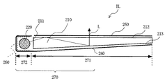
図2に、リフレクタ一体型反射シートRFSを用いて構成されたバックライトBLの横断面を示す。なお、図2に示す横断面図は、光源の位置を除いて図3(b)に示された従来の液晶表示装置の横断面図と基本的に同様に、本発明の実施の形態に係る面状光源装置であるバックライトBLの構造を模式的に表している。具体的には、バックライトBLは、リフレクタ一体型反射シートRFSの鏡面反射部272に形成されたコの字状の部分に冷陰極線管220が装着され、拡散反射部271の上部に導光板210が配置される。そして、導光板210の出射面212の上に光学シート250が適宜配置される。なお、図2において、鏡面反射部272の表面に積層されている鏡面反射フィルム260が点線で示されている。
FIG. 2 shows a cross section of a backlight BL configured using a reflector-integrated reflection sheet RFS. The cross-sectional view shown in FIG. 2 is basically the same as the cross-sectional view of the conventional liquid crystal display device shown in FIG. 3B except for the position of the light source, according to the embodiment of the present invention. The structure of the backlight BL which is a planar light source device is typically represented. Specifically, in the backlight BL, a cold
上述のように、バックライトBLにおいては、導光板210の反射面213からの漏れ光を観察側に反射する反射シート(拡散反射部271)と光源の光を導光板入射面に導くためのリフレクタ(鏡面反射部272)とが一体化して、リフレクタ一体型反射シートRFSとして構成されている。結果、バックライトBLの部品点数と共に組み立て工数を抑えることができ、製造コストを低減できる。また、反射シート(拡散反射部271)とリフレクタ(鏡面反射部272)とは一体に形成されているので、互いの位置ずれによる漏れ光や光損失が発生することは無い。
As described above, in the backlight BL, the reflection sheet (diffuse reflection portion 271) that reflects the leakage light from the
つまり、本発明に係る面光源装置の特徴は、導光板210の反射面213からの漏れ光を観察側に反射する領域を拡散反射(拡散反射部271)とし、光源の光を導光板210の入射面211に導くための反射領域を鏡面反射(鏡面反射部272)とすることにある。以下に、上述の本発明に係るリフレクタ一体型反射シートRFSの拡散反射部271と鏡面反射部272とに対応する部分を、拡散反射部271のみで構成する場合或いは鏡面反射部272のみで構成する場合について説明する。
That is, the surface light source device according to the present invention is characterized in that a region in which leakage light from the
先ず、拡散反射部271のみで構成する場合には、拡散反射シート240に鏡面反射フィルム260を貼り合わせる工程を省略でき、本発明に係るリフレクタ一体型反射シートRFSに比べて、さらに、部品点数および組み立て工数の低減による一層のコスト低減および工数低減が期待される。しかしながら、光源部(220)に鏡面反射部272の代わりに拡散反射部271が適応されることにより、光源から発せられた光が拡散反射されて、光源自身の方向に戻る光の成分が増加して導光板210への光の入射効率が低下するという問題が生じる。
First, in the case of only the diffuse
一方、本発明に係るリフレクタ一体型反射シートRFSの拡散反射部271と鏡面反射部272とに対応する部分を、鏡面反射部272のみで構成した場合には、光源から発せられた光が導光板210の出射面212から射出される出射効率が僅かに向上する。しかしながら、以下に述べる3つの問題が新たに生じる。
On the other hand, when the part corresponding to the diffuse
第1の問題は、部品のコストの増大である。つまり、鏡面反射部272の構成に用いられる金属蒸着フィルムおよび積層型鏡面反射フィルム等の鏡面反射フィルム材は、拡散反射部271の構成に用いられる微細発泡シートに比べるとはるかに高価である。よって、拡散反射部271を置き換える部分だけ鏡面反射フィルム材と微細発泡シートとのコスト差額に相当して部品コストが増大し、結果としてバックライト自体のコストも増大する。
The first problem is an increase in the cost of parts. That is, specular reflection film materials such as a metal vapor deposition film and a laminated specular reflection film used for the configuration of the
第2の問題は、部品重量の増大である。つまり、鏡面反射部272の構成に用いられる金属蒸着フィルムの基材は表面の平滑な透明フィルムで構成する必要がある。このようなフィルムは、微細発泡シートに比べ比重が大きく重量を要する。よって、拡散反射部271を置き換える部分だけ鏡面反射フィルム材の重量に相当する部品重量が増大し、結果としてバックライト自体の重量も増大する。つまり、積層型鏡面反射フィルムもそれ自身は薄く自立出来ないために、鏡面反射フィルム材や微細発泡シートと同等の機械強度を有する基材に貼り付ける必要が有り、その分だけ部品重量が増大する。
The second problem is an increase in component weight. That is, the base material of the metal vapor deposition film used for the configuration of the
第3の問題は、バックライトBLの歩留まりの低下である。つまり、拡散反射部271では目立たないような導光板210に存在する微小な欠陥でも、導光板210の裏面に配置された鏡面反射部272によって拡大反射されて、導光板210の出射面212を介してはっきりと表示されてしまい、バックライトBLとしての使用に耐えないものになる。結果、バックライトBLの製造歩留まりが減少する。
The third problem is a decrease in the yield of the backlight BL. That is, even a minute defect present in the
一方、本発明に係るリフレクタ一体型反射シートRFSは、高価且つ重い鏡面反射部272を、特に光漏れ対策に効果の大きな部分に限定した上で鏡面反射部272と一体化して構成されているので、低組み立て工数、軽量、高組み立て精度、および高コストパフフォーマンスを実現している。
On the other hand, the reflector-integrated reflection sheet RFS according to the present invention is configured by integrating the expensive and heavy
本発明に係る面光源装置は、軽量および薄型化が要求される液晶表示装置等のバックライトに用いることができる。 The surface light source device according to the present invention can be used for a backlight of a liquid crystal display device or the like that is required to be lightweight and thin.
BL バックライト
RFS リフレクタ一体型反射シート
110、210 導光板
111 入射面
112 出射面
113 反射面
120、220 冷陰極線管
130 リフレクタ
140 反射シート
150 光学フィルム
240 拡散反射シート
260 鏡面反射フィルム
270 積層反射シート
271 拡散反射部
272 鏡面反射部
BL Backlight RFS Reflector-integrated
Claims (7)
前記入射面に光を供給する光源と、
前記反射面に配置された光を拡散反射する拡散反射面と、前記光源を囲み前記入射面に対応する開口を有して光を鏡面反射する鏡面反射面とが一体に形成されたリフレクタ一体型反射シートとを備える面光源装置。 The light introduced from the incident surface located on the side surface is propagated to the entire surface while repeating total reflection between the reflecting surface and the emitting surface facing each other, and a part of the light is scattered from the emitting surface. A light guide plate that emits a planar illumination; and
A light source for supplying light to the incident surface;
A reflector integrated type in which a diffuse reflection surface that diffuses and reflects light disposed on the reflection surface and a specular reflection surface that surrounds the light source and has an opening corresponding to the incident surface and that specularly reflects light are integrally formed. A surface light source device comprising a reflection sheet.
Priority Applications (1)
| Application Number | Priority Date | Filing Date | Title |
|---|---|---|---|
| JP2005176790A JP2006351387A (en) | 2005-06-16 | 2005-06-16 | Surface light source device, and liquid crystal display device |
Applications Claiming Priority (1)
| Application Number | Priority Date | Filing Date | Title |
|---|---|---|---|
| JP2005176790A JP2006351387A (en) | 2005-06-16 | 2005-06-16 | Surface light source device, and liquid crystal display device |
Publications (2)
| Publication Number | Publication Date |
|---|---|
| JP2006351387A true JP2006351387A (en) | 2006-12-28 |
| JP2006351387A5 JP2006351387A5 (en) | 2008-06-19 |
Family
ID=37647012
Family Applications (1)
| Application Number | Title | Priority Date | Filing Date |
|---|---|---|---|
| JP2005176790A Pending JP2006351387A (en) | 2005-06-16 | 2005-06-16 | Surface light source device, and liquid crystal display device |
Country Status (1)
| Country | Link |
|---|---|
| JP (1) | JP2006351387A (en) |
Cited By (4)
| Publication number | Priority date | Publication date | Assignee | Title |
|---|---|---|---|---|
| JP2009300868A (en) * | 2008-06-16 | 2009-12-24 | Furukawa Electric Co Ltd:The | Reflector, back light apparatus, liquid crystal display apparatus and method for manufacturing reflector |
| US8026995B2 (en) | 2008-03-19 | 2011-09-27 | Samsung Electronics Co., Ltd. | Liquid crystal display and method of fabricating the same |
| JP2012054008A (en) * | 2010-08-31 | 2012-03-15 | Longeval Precision Technological Corp | Light-emitting device and backlight module equipped with this light-emitting device |
| JP2017091839A (en) * | 2015-11-11 | 2017-05-25 | パナソニックIpマネジメント株式会社 | Light guide body |
Citations (3)
| Publication number | Priority date | Publication date | Assignee | Title |
|---|---|---|---|---|
| JPH05341134A (en) * | 1992-06-04 | 1993-12-24 | Tosoh Corp | Back light |
| JPH06235918A (en) * | 1993-02-09 | 1994-08-23 | Ohtsu Tire & Rubber Co Ltd :The | Light guide device |
| JP2005108788A (en) * | 2003-10-02 | 2005-04-21 | Shinwa:Kk | Reflection structure and reflection sheet |
-
2005
- 2005-06-16 JP JP2005176790A patent/JP2006351387A/en active Pending
Patent Citations (3)
| Publication number | Priority date | Publication date | Assignee | Title |
|---|---|---|---|---|
| JPH05341134A (en) * | 1992-06-04 | 1993-12-24 | Tosoh Corp | Back light |
| JPH06235918A (en) * | 1993-02-09 | 1994-08-23 | Ohtsu Tire & Rubber Co Ltd :The | Light guide device |
| JP2005108788A (en) * | 2003-10-02 | 2005-04-21 | Shinwa:Kk | Reflection structure and reflection sheet |
Cited By (4)
| Publication number | Priority date | Publication date | Assignee | Title |
|---|---|---|---|---|
| US8026995B2 (en) | 2008-03-19 | 2011-09-27 | Samsung Electronics Co., Ltd. | Liquid crystal display and method of fabricating the same |
| JP2009300868A (en) * | 2008-06-16 | 2009-12-24 | Furukawa Electric Co Ltd:The | Reflector, back light apparatus, liquid crystal display apparatus and method for manufacturing reflector |
| JP2012054008A (en) * | 2010-08-31 | 2012-03-15 | Longeval Precision Technological Corp | Light-emitting device and backlight module equipped with this light-emitting device |
| JP2017091839A (en) * | 2015-11-11 | 2017-05-25 | パナソニックIpマネジメント株式会社 | Light guide body |
Similar Documents
| Publication | Publication Date | Title |
|---|---|---|
| JP5147250B2 (en) | Liquid crystal display | |
| JP5275441B2 (en) | Light guide, surface light source device, and liquid crystal display device | |
| US7161644B2 (en) | Backlight assembly and liquid crystal display device using the same | |
| US20080278658A1 (en) | Front light unit and flat display apparatus employing the same | |
| WO2010038516A1 (en) | Illuminating device, planar light source device and liquid crystal display device | |
| JP3833639B2 (en) | Backlight module of liquid crystal display device | |
| US20070081111A1 (en) | Double-sided backlight module and double-sided liquid crystal display with same | |
| US20120320624A1 (en) | Illuminating device and display device | |
| TW201319694A (en) | Display apparatus and backlight module thereof | |
| WO2010001653A1 (en) | Light guide unit, planar light source device and liquid crystal display device | |
| JP2006351387A (en) | Surface light source device, and liquid crystal display device | |
| JP4411186B2 (en) | Liquid crystal display | |
| JP2009176512A (en) | Surface light source device and image display apparatus | |
| WO2013125134A1 (en) | Light source module, and liquid crystal display device | |
| CN103105695A (en) | Liquid crystal panel assembly and image display apparatus having the same | |
| JP2007256697A (en) | Liquid crystal display | |
| KR20110026958A (en) | Liquid crystal display device | |
| JP4353279B2 (en) | Display device and mobile phone | |
| JP2007059168A (en) | Backlight | |
| JP2006134661A (en) | Planar light source and liquid crystal display device using this | |
| JP2002323607A (en) | Light control sheet, surface light source device and image display | |
| WO2012043361A1 (en) | Illumination device and display device | |
| EP2172700B1 (en) | Back light unit and image display device using the same | |
| JP5929552B2 (en) | Light guide plate, surface light source device, transmissive display device | |
| JPH11329042A (en) | Flat surface light source, exposing element and flat surface display device |
Legal Events
| Date | Code | Title | Description |
|---|---|---|---|
| A521 | Written amendment |
Free format text: JAPANESE INTERMEDIATE CODE: A523 Effective date: 20080507 |
|
| A621 | Written request for application examination |
Free format text: JAPANESE INTERMEDIATE CODE: A621 Effective date: 20080507 |
|
| A977 | Report on retrieval |
Free format text: JAPANESE INTERMEDIATE CODE: A971007 Effective date: 20091203 |
|
| A131 | Notification of reasons for refusal |
Free format text: JAPANESE INTERMEDIATE CODE: A131 Effective date: 20091216 |
|
| A02 | Decision of refusal |
Free format text: JAPANESE INTERMEDIATE CODE: A02 Effective date: 20100416 |