JP5929552B2 - Light guide plate, surface light source device, transmissive display device - Google Patents

Light guide plate, surface light source device, transmissive display device Download PDF

Info

Publication number
JP5929552B2
JP5929552B2 JP2012144569A JP2012144569A JP5929552B2 JP 5929552 B2 JP5929552 B2 JP 5929552B2 JP 2012144569 A JP2012144569 A JP 2012144569A JP 2012144569 A JP2012144569 A JP 2012144569A JP 5929552 B2 JP5929552 B2 JP 5929552B2
Authority
JP
Japan
Prior art keywords
light
guide plate
light guide
back side
unit optical
Prior art date
Legal status (The legal status is an assumption and is not a legal conclusion. Google has not performed a legal analysis and makes no representation as to the accuracy of the status listed.)
Active
Application number
JP2012144569A
Other languages
Japanese (ja)
Other versions
JP2014010911A (en
Inventor
後藤 正浩
正浩 後藤
関口 博
博 関口
Current Assignee (The listed assignees may be inaccurate. Google has not performed a legal analysis and makes no representation or warranty as to the accuracy of the list.)
Dai Nippon Printing Co Ltd
Original Assignee
Dai Nippon Printing Co Ltd
Priority date (The priority date is an assumption and is not a legal conclusion. Google has not performed a legal analysis and makes no representation as to the accuracy of the date listed.)
Filing date
Publication date
Application filed by Dai Nippon Printing Co Ltd filed Critical Dai Nippon Printing Co Ltd
Priority to JP2012144569A priority Critical patent/JP5929552B2/en
Publication of JP2014010911A publication Critical patent/JP2014010911A/en
Application granted granted Critical
Publication of JP5929552B2 publication Critical patent/JP5929552B2/en
Active legal-status Critical Current
Anticipated expiration legal-status Critical

Links

Images

Landscapes

  • Liquid Crystal (AREA)
  • Planar Illumination Modules (AREA)

Description

本発明は、導光板、及び、これを備える面光源装置、透過型表示装置に関するものである。   The present invention relates to a light guide plate, a surface light source device including the same, and a transmissive display device.

従来、LCD(Liquid Crystal Display)パネル等の透過型表示部を背面から面光源装置(バックライト)によって照明し、映像を表示する透過型表示装置が知られている。
面光源装置は、大きく分けて、各種光学シート等の光学部材の直下に光源を配置する直下型のものと、光学部材の側面側に光源が配置されるエッジライト型のものがある。このエッジライト型の面光源装置は、光源を導光板等の光学部材の側面側に配置することから、直下型のものに比べて面光源装置をより薄型化できるという利点を有し、近年広く用いられている。
2. Description of the Related Art Conventionally, a transmissive display device that displays an image by illuminating a transmissive display unit such as an LCD (Liquid Crystal Display) panel from the back with a surface light source device (backlight) is known.
Surface light source devices are broadly classified into a direct type in which a light source is arranged directly under an optical member such as various optical sheets and an edge light type in which a light source is arranged on a side surface side of the optical member. This edge light type surface light source device has an advantage that the surface light source device can be made thinner than the direct type since the light source is arranged on the side surface side of the optical member such as a light guide plate. It is used.

一般的に、エッジライト型の面光源装置では、導光板の側面である入光面に対面する位置に光源が配置されており、光源が発する光は、入光面から導光板に入射し、出光面とこれに対向する背面とで反射を繰り返しながら、入光面に略直交する方向(導光方向)へ進む。
そして、導光板の背面に設けられた拡散パターンやプリズム形状等によって光の進行方向を変化させることにより、出光面の導光方向に沿った各位置から少しずつ光がLCDパネル側へ出光していく(例えば、特許文献1〜4参照)。
Generally, in an edge light type surface light source device, a light source is disposed at a position facing a light incident surface that is a side surface of a light guide plate, and light emitted from the light source enters the light guide plate from the light incident surface, While repeating reflection at the light exit surface and the back surface opposite to the light exit surface, the light travels in a direction substantially perpendicular to the light entrance surface (light guide direction).
Then, by changing the traveling direction of the light according to the diffusion pattern or prism shape provided on the back surface of the light guide plate, light is gradually emitted from each position along the light guide direction of the light exit surface to the LCD panel side. (For example, see Patent Documents 1 to 4).

特開平9−43433号公報JP-A-9-43433 特開2007−227405号公報JP 2007-227405 A 特開2005−259361号公報JP 2005-259361 A 特開平9−166713号公報JP-A-9-166713

例えば、特許文献1,2に示すような背面に拡散パターンを有する導光板を用いた場合には、光が背面の拡散パターンによって拡散反射されて出光するため、光の収束性が低下し、正面輝度が低下するという問題がある。また、このような導光板を用いた場合には、導光方向以外の方向にも光が拡散反射されるため、導光効率が低下し、導光方向において光源から遠い側が暗くなるという問題が生じる場合がある。
そのため、近年では、特許文献3,4に示すような、背面にプリズム形状が複数配列された導光板が広く用いられるようになってきている。このような導光板は、光を拡散反射しないので、正面輝度を高くすることができ、また、導光方向において、光源から離れた領域であっても、十分に導光することができ、光の均一性も良好である。
For example, when using a light guide plate having a diffusion pattern on the back surface as shown in Patent Documents 1 and 2, the light is diffused and reflected by the diffusion pattern on the back surface, and thus the light convergence is reduced, and the front surface is reduced. There is a problem that the luminance is lowered. In addition, when such a light guide plate is used, light is diffusely reflected in directions other than the light guide direction, so that the light guide efficiency is lowered and the side far from the light source in the light guide direction is dark. May occur.
Therefore, in recent years, as shown in Patent Documents 3 and 4, a light guide plate having a plurality of prism shapes arranged on the back surface has been widely used. Since such a light guide plate does not diffusely reflect light, the front luminance can be increased, and even in a region away from the light source in the light guide direction, light can be sufficiently guided, The uniformity is also good.

しかし、このような背面側にプリズム形状を有する導光板では、組み立て作業中や搬送中等において、プリズム形状の頂部や光が反射する斜面が傷付き易く、その傷ついた部分に入光面からの光が入射すると、その光が拡散反射されて一部が出光面から出射する等し、導光効率の低下や、輝度ムラ等を招くという問題があった。   However, in such a light guide plate having a prism shape on the back side, the top of the prism shape and the inclined surface on which the light is reflected are easily damaged during assembly work, transportation, etc., and the light from the light incident surface is applied to the damaged part. When the light is incident, there is a problem that the light is diffusely reflected and a part of the light is emitted from the light exit surface, leading to a decrease in light guide efficiency and luminance unevenness.

本発明の課題は、導光効率が高く、明るさの均一性の高い良好な導光板、及び、これを備える面光源装置、透過型表示装置を提供することである。   An object of the present invention is to provide a good light guide plate with high light guide efficiency and high brightness uniformity, a surface light source device including the same, and a transmissive display device.

本発明は、以下のような解決手段により、前記課題を解決する。なお、理解を容易にするために、本発明の実施形態に対応する符号を付して説明するが、これに限定されるものではない。
請求項1の発明は、面光源装置に用いられ、光が入射する入光面(13a)と、前記入光面に交差し光が出射する出光面(13c)と、前記出光面に対向する背面(13d)とを有し、前記入光面から入射した光を、入光面側から前記入光面に対向する対向面側へと向かう導光方向に導光しながら前記出光面から出射する導光板であって、前記背面に、背面側単位光学形状(133)が前記導光方向に平行に複数配列されて設けられ、前記背面側単位光学形状は、背面側に凸となる柱状であり、該導光板よりも背面(13d)側に位置する部材と接する接触部を有する頂面部(133c)と、前記背面側単位光学形状の配列方向において、前記頂面部よりも入光面側に位置する第1斜面部(133a)と、対向面側に位置して入射する光の少なくとも一部を全反射する第2斜面部(133b)とを有し、少なくとも前記第1斜面部及び前記接触部は、前記入光面から前記導光方向に進む光が入射しない領域に位置し、前記背面側単位光学形状の配列方向において、前記頂面部の少なくとも前記第2斜面部に隣接する領域は、その入光面側端部が対向面側端部よりも背面側に位置するように、前記背面に対して、0°<α≦1°を満たす角度αをなすこと、特徴とする導光板(13)である。
請求項2の発明は、請求項1に記載の導光板において、前記背面側単位光学形状(133)の間の谷底となる点(133v)から前記接触部(133t)まの前記背面の法線方向における寸法(H1)は、1μm以上50μm以下であること、を特徴とする導光板(13)である。
請求項3の発明は、請求項1又は請求項2に記載の導光板において、前記背面側単位光学形状(131)の配列方向における前記光が到達しない領域(A)の幅(W)が、前記背面側単位光学形状の配列ピッチ(P1)に対する割合は、5%以上であること、を特徴とする導光板(13)である。
請求項4の発明は、請求項1から請求項3までのいずれか1項に記載の導光板において、前記第1斜面部(133a)が該導光板の板面となす角度をβ、前記出光面(13c)での臨界角をθ、前記第2斜面部(133b)が前記板面となす角度γとするとき、角度βは、(90°−θ)<β、かつ、γ<βを満たすこと、を特徴とする導光板(13)である。
請求項5の発明は、請求項1から請求項4までのいずれか1項に記載の導光板において、前記接触部(133t)は、背面(13d)側に凸となる曲面上に位置すること、を特徴とする導光板(13)である。
The present invention solves the above problems by the following means. In addition, in order to make an understanding easy, although the code | symbol corresponding to embodiment of this invention is attached | subjected and demonstrated, it is not limited to this.
The invention of claim 1 is used in a surface light source device, and is opposed to the light incident surface (13a) on which light is incident, a light exit surface (13c) that intersects the light incident surface and emits light, and the light exit surface. The light incident from the light incident surface is emitted from the light exit surface while being guided in the light guide direction from the light incident surface toward the opposite surface opposite the light incident surface. A plurality of back side unit optical shapes (133) arranged in parallel to the light guide direction, and the back side unit optical shape is a columnar shape convex toward the back side. And a top surface portion (133c) having a contact portion in contact with a member located on the back surface (13d) side of the light guide plate, and in the arrangement direction of the back side unit optical shape, on the light incident surface side from the top surface portion. a first inclined surface portion located (133a), less of the incident light is located on the opposite surface side A second slope part (133b) that totally reflects at least a part, and at least the first slope part and the contact part are located in a region where light traveling in the light guide direction from the light incident surface is not incident. And, in the arrangement direction of the back side unit optical shapes, at least the area of the top surface portion adjacent to the second slope portion is such that the light incident surface side end portion is located on the back side with respect to the opposing surface side end portion. to, to the rear, it is 0 ° <α ≦ 1 ° satisfies that an angle alpha, the light guide plate, wherein (13).
According to a second aspect of the present invention, in the light guide plate according to the first aspect, a normal line of the back surface from a point (133v) which becomes a valley bottom between the back-side unit optical shapes (133) to the contact portion (133t). The light guide plate (13) is characterized in that a dimension (H1) in the direction is 1 μm or more and 50 μm or less.
The invention according to claim 3 is the light guide plate according to claim 1 or 2, wherein the width (W) of the region (A) where the light does not reach in the arrangement direction of the back unit optical shape (131), A ratio of the back side unit optical shape to the arrangement pitch (P1) is 5% or more.
According to a fourth aspect of the present invention, in the light guide plate according to any one of the first to third aspects, an angle formed by the first inclined surface portion (133a) with the plate surface of the light guide plate is β, and the light output When the critical angle at the surface (13c) is θ and the angle γ between the second slope (133b) and the plate surface is the angle β, (90 ° −θ) <β and γ <β. A light guide plate (13) characterized by satisfying.
According to a fifth aspect of the present invention, in the light guide plate according to any one of the first to fourth aspects, the contact portion (133t) is located on a curved surface that protrudes toward the back surface (13d). A light guide plate (13) characterized by the above.

請求項6の発明は、請求項1から請求項5までのいずれか1項に記載の導光板(13)と、前記入光面(13a)に対面する位置に設けられ、前記入光面へ光を投射する光源部(12)と、前記導光板の出光面(13c)側に配置され、前記導光板から出射した光を、そのシート面の法線方向又は法線方向となす角度が小さくなる方向へ向ける偏向作用を有する偏向光学シートと、を備える面光源装置(10)である。
請求項7の発明は、請求項6に記載の面光源装置(10)と、前記面光源装置によって背面側から照明される透過型表示部(11)と、を備える透過型表示装置(1)である。
The invention of claim 6 is provided at a position facing the light guide plate (13) according to any one of claims 1 to 5 and the light incident surface (13a), to the light incident surface. The light source part (12) that projects light and the light exit surface (13c) side of the light guide plate, and the angle that makes the light emitted from the light guide plate the normal direction or normal direction of the sheet surface is small. A surface light source device (10) including a deflecting optical sheet having a deflecting action toward a certain direction.
The invention of claim 7 is a transmissive display device (1) comprising the surface light source device (10) according to claim 6 and a transmissive display unit (11) illuminated from the back side by the surface light source device. It is.

本発明によれば、導光効率が高く、明るさの均一性の高い良好な導光板とすることができる。また、本発明によれば、そのような導光板を備えることにより、光の利用効率が高く、明るさの均一性の高い良好な面光源装置、透過型表示装置とすることができる。   ADVANTAGE OF THE INVENTION According to this invention, it can be set as the favorable light-guide plate with high light guide efficiency and high uniformity of brightness. Further, according to the present invention, by providing such a light guide plate, it is possible to provide a good surface light source device and a transmissive display device with high light utilization efficiency and high brightness uniformity.

実施形態の透過型表示装置1を説明する図である。It is a figure explaining the transmissive display apparatus 1 of embodiment. 実施形態の導光板13の形状を説明する図である。It is a figure explaining the shape of the light-guide plate 13 of embodiment. 実施形態の背面側単位光学形状133を説明する図である。It is a figure explaining the back side unit optical shape 133 of an embodiment. 実施形態の背面側単位光学形状133の他の形状の例を説明する図である。It is a figure explaining the example of the other shape of the back side unit optical shape 133 of an embodiment. プリズムシート14を説明する図である。It is a figure explaining the prism sheet. 比較例1,2の導光板73,83の背面側単位光学形状733,833を説明する図である。It is a figure explaining back side unit optical shape 733,833 of light guide plates 73 and 83 of comparative examples 1 and 2.

以下、図面等を参照して、本発明の実施形態について説明する。
なお、図1を含め、以下に示す各図は、模式的に示した図であり、各部の大きさ、形状は、理解を容易にするために、適宜誇張している。
また、板、シート等の言葉を使用しているが、これらは、一般的な使い方として、厚さの厚い順に、板、シート、フィルムの順で使用されており、本明細書中でもそれに倣って使用している。しかし、このような使い分けには、技術的な意味は無いので、これらの文言は、適宜置き換えることができるものとする。
さらに、本明細書中において、シート面(板面,フィルム面)とは、各シート(板,フィルム)において、そのシート(板,フィルム)全体として見たときにおける、シート(板,フィルム)の平面方向となる面を示すものであるとする。
Embodiments of the present invention will be described below with reference to the drawings.
In addition, each figure shown below including FIG. 1 is the figure shown typically, and the magnitude | size and shape of each part are exaggerated suitably for easy understanding.
In addition, words such as plate and sheet are used, but these are generally used in the order of thickness, plate, sheet, and film in order of increasing thickness. I use it. However, there is no technical meaning in such proper use, so these terms can be replaced as appropriate.
Further, in this specification, the sheet surface (plate surface, film surface) is the sheet (plate, film) of each sheet (plate, film) when viewed as the whole sheet (plate, film). Suppose that the surface which becomes a plane direction is shown.

本明細書中において、形状や幾何学的条件を特定する用語、例えば、平行や直交等の用語については、厳密に意味するところに加え、同様の光学的機能を奏し、平行や直交と見なせる程度の誤差を有する状態も含むものとする。
また、本明細書中に記載する各部材の寸法等の数値及び材料名等は、実施形態としての一例であり、これに限定されるものではなく、適宜選択して使用してよい。
In this specification, terms that specify shape and geometric conditions, for example, terms such as parallel and orthogonal, are strictly meanings, have similar optical functions, and can be regarded as parallel and orthogonal It also includes a state having an error of.
In addition, the numerical values such as the dimensions of the respective members and the material names described in the present specification are examples of the embodiment, and are not limited thereto, and may be appropriately selected and used.

(実施形態)
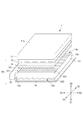
図1は、本実施形態の透過型表示装置1を説明する図である。
本実施形態の透過型表示装置1は、LCDパネル11と面光源装置10とを備えている。透過型表示装置1は、LCDパネル11を背面側から面光源装置10で照明し、LCDパネル11に形成される映像情報を表示する。
なお、図1を含め以下の図中及び以下の説明において、理解を容易にするために、透過型表示装置1の使用状態において、透過型表示装置1の画面に平行であって互いに直交する2方向をX方向(X1−X2方向)、Y方向(Y1−Y2方向)とし、透過型表示装置1の画面に直交する方向をZ方向(Z1−Z2方向)とする。なお、Z方向においてZ1側が背面側であり、Z2側は観察者側である。
本実施形態の透過型表示装置1の画面は、LCDパネル11の最も観察者側の面(以下、表示面という)11aに相当し、透過型表示装置1の「正面方向」とは、この表示面11aの法線方向であり、Z方向に平行であり、後述するプリズムシート14のシート面や、導光板13の板面等への法線方向と一致するものとする。
(Embodiment)
FIG. 1 is a diagram illustrating a transmissive display device 1 according to the present embodiment.
The transmissive display device 1 of the present embodiment includes an LCD panel 11 and a surface light source device 10. The transmissive display device 1 illuminates the LCD panel 11 with the surface light source device 10 from the back side, and displays video information formed on the LCD panel 11.
In addition, in the following drawings including FIG. 1 and the following description, in order to facilitate understanding, when the transmissive display device 1 is in use, the transmissive display device 1 is parallel to the screen of the transmissive display device 1 and orthogonal to each other. The directions are the X direction (X1-X2 direction) and the Y direction (Y1-Y2 direction), and the direction orthogonal to the screen of the transmissive display device 1 is the Z direction (Z1-Z2 direction). In the Z direction, the Z1 side is the back side, and the Z2 side is the observer side.
The screen of the transmissive display device 1 of the present embodiment corresponds to the surface 11a closest to the viewer (hereinafter referred to as a display surface) 11a of the LCD panel 11, and the “front direction” of the transmissive display device 1 is the display. It is the normal direction of the surface 11a, parallel to the Z direction, and coincides with the normal direction to the sheet surface of the prism sheet 14 described later, the plate surface of the light guide plate 13, and the like.

LCDパネル11は、透過型の液晶表示素子により形成され、その表示面に映像情報を形成する透過型表示部である。
本実施形態のLCDパネル1は、略平板状であり、LCDパネル11の外形及び表示面11aは、Z方向から見て矩形形状である。そして、LCDパネル11及びLCDパネル11を構成する各部材は、Z方向から見て、X方向に平行な対向する2辺と、Y方向に平行な対向する2辺とを有している。
The LCD panel 11 is a transmissive display unit that is formed of a transmissive liquid crystal display element and forms video information on its display surface.
The LCD panel 1 of the present embodiment is substantially flat, and the outer shape of the LCD panel 11 and the display surface 11a are rectangular when viewed from the Z direction. The LCD panel 11 and each member constituting the LCD panel 11 have two opposite sides parallel to the X direction and two opposite sides parallel to the Y direction when viewed from the Z direction.

面光源装置10は、LCDパネル11を背面側から照明する装置であり、光源部12、導光板13、プリズムシート14、光拡散シート15、反射シート16を備えている。この面光源装置10は、所謂、エッジライト型の面光源装置(バックライト)である。この面光源装置10を構成する導光板13、プリズムシート14、光拡散シート15、反射シート16等は、正面方向(Z方向)から見て矩形形状であり、X方向に平行な対向する2辺と、Y方向に平行な対向する2辺とを有している。   The surface light source device 10 is a device that illuminates the LCD panel 11 from the back side, and includes a light source unit 12, a light guide plate 13, a prism sheet 14, a light diffusion sheet 15, and a reflection sheet 16. The surface light source device 10 is a so-called edge light type surface light source device (backlight). The light guide plate 13, the prism sheet 14, the light diffusion sheet 15, the reflection sheet 16, and the like constituting the surface light source device 10 are rectangular when viewed from the front direction (Z direction) and are opposed to two sides parallel to the X direction. And two opposite sides parallel to the Y direction.

光源部12は、LCDパネル11を照明する光を発する部分である。この光源部12は、導光板13のX方向の一方(X1側)の端面である入光面13aに対面する位置に、Y方向に沿って配置されている。
光源部12は、点光源121がY方向に所定の間隔で複数配列されて形成されている。本実施形態では、点光源121は、LED(Light Emitting Diode)光源を用いている。なお、光源部12は、例えば、冷陰極管等の線光源としてもよいし、Y方向に延在するライトガイドの端面に光源を配置した形態としてもよい。また、光源部12の発する光の利用効率を向上させる観点から、光源部12の外側を覆うように不図示の反射板を設けてもよい。
The light source unit 12 is a part that emits light that illuminates the LCD panel 11. The light source unit 12 is disposed along the Y direction at a position facing the light incident surface 13a that is one end surface (X1 side) of the light guide plate 13 in the X direction (X1 side).
The light source unit 12 is formed by arranging a plurality of point light sources 121 at predetermined intervals in the Y direction. In the present embodiment, the point light source 121 uses an LED (Light Emitting Diode) light source. The light source unit 12 may be, for example, a line light source such as a cold cathode tube, or may have a form in which a light source is disposed on an end surface of a light guide extending in the Y direction. Further, from the viewpoint of improving the utilization efficiency of light emitted from the light source unit 12, a reflection plate (not shown) may be provided so as to cover the outside of the light source unit 12.

導光板13は、光を導光する略平板状の部材である。本実施形態では、入光面13a及び対向面13bは、導光板13のX方向の両端部に位置し、板面の法線方向(Z方向)から見て、Y方向に平行な2辺である。この入光面13a及び対向面13bは、Y方向に延在し、X方向及びZ方向に直交している。また、導光板13の板面は、XY面に平行であり、出光面13cは、この板面に平行な面であるとする。
この導光板13は、光源部12が発する光を入光面13aから入射させ、出光面13cと背面13dとで全反射させながら、入光面13aに対向する対向面13b側(X2側)へ、主としてX方向に導光しながら、出光面13cからプリズムシート14側(Z2側)へ適宜出射させる。
The light guide plate 13 is a substantially flat member that guides light. In the present embodiment, the light incident surface 13a and the opposing surface 13b are located at both ends in the X direction of the light guide plate 13 and are two sides parallel to the Y direction when viewed from the normal direction (Z direction) of the plate surface. is there. The light incident surface 13a and the facing surface 13b extend in the Y direction and are orthogonal to the X direction and the Z direction. The plate surface of the light guide plate 13 is parallel to the XY plane, and the light output surface 13c is a surface parallel to the plate surface.
The light guide plate 13 allows light emitted from the light source unit 12 to be incident from the light incident surface 13a, and is totally reflected by the light output surface 13c and the back surface 13d, to the opposite surface 13b side (X2 side) facing the light incident surface 13a. The light is appropriately emitted from the light exit surface 13c to the prism sheet 14 side (Z2 side) while being guided mainly in the X direction.

図2は、本実施形態の導光板13の形状を説明する図である。図2(a)は、出光側単位光学形状131を説明する図であり、図2(b)は、背面側単位光学形状133を説明する図である。図2(a)では、導光板13のYZ面に平行な断面の一部を拡大して示している。図2(b)では、導光板13のXZ面に平行な断面の一部を拡大して示している。
図3は、本実施形態の背面側単位光学形状133を説明する図である。図3では、図2(b)に示す導光板13のXZ面に平行な断面の一部をさらに拡大して示している。
導光板13は、図2に示すように、導光板13の出光面13cには、出光側単位光学形状131が複数配列して形成される出光側光学形状部132を有し、背面13dには、背面側単位光学形状133が複数配列されて形成される背面側光学形状部134を有している。また、導光板13は、板面の法線方向(Z方向)において、出光側光学形状部132と背面側光学形状部134との間に、単位光学形状等が形成されていない略平板状の部分である本体部135を有している。この本体部135と出光側光学形状部132と背面側光学形状部134とは、一体に形成されている。
本実施形態では、本体部135は、X方向及びY方向における厚さが一定であり、導光板13の総厚は、一定である。また、本実施形態では、導光板13の背面13dは、出光面13c及びXY面に平行な面であるとする。
FIG. 2 is a diagram illustrating the shape of the light guide plate 13 of the present embodiment. FIG. 2A is a diagram for explaining the light exit side unit optical shape 131, and FIG. 2B is a diagram for explaining the back side unit optical shape 133. FIG. 2A shows an enlarged part of a cross section parallel to the YZ plane of the light guide plate 13. FIG. 2B shows an enlarged part of a cross section of the light guide plate 13 parallel to the XZ plane.
FIG. 3 is a diagram illustrating the back-side unit optical shape 133 of the present embodiment. In FIG. 3, a part of a cross section parallel to the XZ plane of the light guide plate 13 shown in FIG.
As shown in FIG. 2, the light guide plate 13 has a light output side optical shape portion 132 formed by arranging a plurality of light output side unit optical shapes 131 on the light output surface 13c of the light guide plate 13, and a back surface 13d. The rear side optical shape portion 134 is formed by arranging a plurality of back side unit optical shapes 133. The light guide plate 13 has a substantially flat plate shape in which no unit optical shape is formed between the light output side optical shape portion 132 and the back side optical shape portion 134 in the normal direction (Z direction) of the plate surface. It has a main body part 135 which is a part. The main body portion 135, the light output side optical shape portion 132, and the back surface side optical shape portion 134 are integrally formed.
In the present embodiment, the main body 135 has a constant thickness in the X direction and the Y direction, and the total thickness of the light guide plate 13 is constant. In the present embodiment, the back surface 13d of the light guide plate 13 is a surface parallel to the light output surface 13c and the XY plane.

出光側光学形状部132は、導光板13の出光面13cに設けられ、出光側単位光学形状131が複数配列されて形成されている。
出光側単位光学形状131は、図1及び図2(a)に示すように、出光側(LCDパネル11側、Z2側)に凸となる柱状であり、長手方向(稜線方向)をX方向とし、Y方向に複数配列されている。
本実施形態の出光側単位光学形状131は、三角柱状であり、図2(a)に示すように、YZ面に平行な断面形状が頂角δとする二等辺三角形形状である。また、この出光側単位光学形状131の配列ピッチは、P2であり、配列ピッチP2は、出光側単位光学形状131の配列方向の幅W2に等しい(P2=W2)形態となっている。
なお、出光側単位光学形状131は、上記の例に限らず、例えば、長軸が導光板13の板面(出光面13c)に直交する楕円柱の一部形状としてもよいし、円柱の一部形状としてもよいし、複数種類の曲面や平面を組み合わせてなる形状としてもよい。
The light output side optical shape portion 132 is provided on the light output surface 13 c of the light guide plate 13, and is formed by arranging a plurality of light output side unit optical shapes 131.
As shown in FIG. 1 and FIG. 2A, the light exit side unit optical shape 131 is a columnar shape convex to the light exit side (LCD panel 11 side, Z2 side), and the longitudinal direction (ridge line direction) is the X direction. Are arranged in the Y direction.
The light output side unit optical shape 131 of the present embodiment has a triangular prism shape, and is an isosceles triangular shape having a cross-sectional shape parallel to the YZ plane as an apex angle δ, as shown in FIG. Further, the arrangement pitch of the light output side unit optical shapes 131 is P2, and the arrangement pitch P2 is equal to the width W2 in the arrangement direction of the light output side unit optical shapes 131 (P2 = W2).
The light output side unit optical shape 131 is not limited to the above example. For example, the light output side unit optical shape 131 may be a partial shape of an elliptic cylinder whose major axis is orthogonal to the plate surface of the light guide plate 13 (light output surface 13c). It may be a part shape, or may be a shape formed by combining a plurality of types of curved surfaces or planes.

出光側単位光学形状131は、導光板13の光の導光方向(X方向)に直交する方向(Y方向)に配列されており、出光面13cから出射する光に対して、その配列方向における光線制御作用を有する。従って、出光側光学形状部132により、導光板13からの出射光のY方向における明るさの均一性を向上させることができる。なお、このような光線制御作用を必要としない場合には、出光面13cに出光側光学形状部132を形成しない形態としてもよい。   The light output side unit optical shapes 131 are arranged in a direction (Y direction) orthogonal to the light guide direction (X direction) of the light of the light guide plate 13, and the light emitted from the light output surface 13c is arranged in the arrangement direction. Has a light beam control action. Therefore, the light emission side optical shape portion 132 can improve the uniformity of the brightness in the Y direction of the light emitted from the light guide plate 13. In addition, when such a light beam control action is not required, it is good also as a form which does not form the light emission side optical shape part 132 in the light emission surface 13c.

背面側光学形状部134は、導光板13の背面13dに設けられ、背面側単位光学形状133が複数配列されて形成されている。
背面側単位光学形状133は、図1,図2(b),図3に示すように、背面側(Z1側)に凸となる柱状であり、長手方向(稜線方向)をY方向とし、導光方向となるX方向に複数配列されている。
背面側単位光学形状133は、図2(b)に示すように、XZ面に平行な断面における断面形状が略台形状であり、入光面13a側(X1側)に位置する第1斜面部133aと、頂面部133cよりも対向面13b側(X2側)に位置し、入射する光の少なくとも一部を全反射する第2斜面部133bと、第1斜面部133a及び第2斜面部133bとの間に位置し、最も背面側(Z1側)となる頂面部133cとを有している。
また、この背面側単位光学形状133の配列ピッチは、P1であり、配列ピッチP1は、背面側単位光学形状133の配列方向の幅W1に等しい(P1=W1)形態となっている。
The back side optical shape part 134 is provided on the back side 13d of the light guide plate 13, and is formed by arranging a plurality of back side unit optical shapes 133.
As shown in FIGS. 1, 2B, and 3, the back side unit optical shape 133 is a columnar shape that is convex on the back side (Z1 side), and the longitudinal direction (ridge line direction) is the Y direction. A plurality are arranged in the X direction, which is the light direction.
As shown in FIG. 2B, the back unit optical shape 133 has a substantially trapezoidal cross-sectional shape in a cross section parallel to the XZ plane, and is a first slope portion located on the light incident surface 13a side (X1 side). 133a, a second inclined surface portion 133b that is located closer to the opposing surface 13b (X2 side) than the top surface portion 133c and totally reflects at least part of incident light, and a first inclined surface portion 133a and a second inclined surface portion 133b, And a top surface portion 133c which is the rearmost side (Z1 side).
The arrangement pitch of the rear unit optical shapes 133 is P1, and the arrangement pitch P1 is equal to the width W1 in the arrangement direction of the rear unit optical shapes 133 (P1 = W1).

第1斜面部133aは、導光板13の板面(本実施形態では、XY面に平行な面)と角度βをなし、第2斜面部133bは、導光板13の板面と角度γをなしている。このとき、角度β,γは、γ<βである。
第1斜面部133aと導光板13の板面とがなす角度βは、図3に示す断面において、出光面13c(XY面に平行な面)における臨界角をθとするとき、(90°−θ)<βを満たしている。従って、入光面13aから対向面13b側へ(X1側からX2側へ)導光する光のうち、出光面13cで全反射して背面側単位光学形状133の間の谷底となる点133vを通って背面側へ進む光L0が第2斜面部133bに入射する点を点133dとすると、点133vよりも対向面13b側であって点133dよりも入光面13a側となる領域A(X方向の幅W)には光は入射せず、点133dを含みその対向面13b側となる領域Bには、光が入射する形態となっている。
The first inclined surface portion 133a forms an angle β with the plate surface of the light guide plate 13 (in this embodiment, a surface parallel to the XY surface), and the second inclined surface portion 133b forms an angle γ with the plate surface of the light guide plate 13. ing. At this time, the angles β and γ satisfy γ <β.
The angle β formed by the first slope portion 133a and the plate surface of the light guide plate 13 is (90 ° − when the critical angle at the light exit surface 13c (surface parallel to the XY plane) is θ in the cross section shown in FIG. θ) <β is satisfied. Therefore, of the light guided from the light incident surface 13a to the facing surface 13b side (from the X1 side to the X2 side), a point 133v that is totally reflected by the light exit surface 13c and becomes a valley bottom between the rear unit optical shapes 133 is obtained. If the point where the light L0 passing through and entering the second inclined surface portion 133b enters the point 133d is a point A, the region A (X that is on the opposite surface 13b side than the point 133v and closer to the light incident surface 13a side than the point 133d. Light is not incident on the direction width W), and light is incident on the region B including the point 133d and facing the facing surface 13b.

また、第2斜面部133bは、導光方向に進む光の一部が入射し、かつ、その入射した光の少なくとも一部を全反射する。従って、光の導光効率及び取り出し効率の双方を向上させる観点から、角度γは、1°<γ≦5°を満たすことが好ましい。
γ≦1°であると、後述する頂面部133cと第2斜面部133bとの傾斜角度の差が小さくなり、略同一面となり、第2斜面部133bの頂面部133c側端部が反射シート16等に接触して傷が付きやすくなる。
また、γ>5°であると、導光方向(X方向)に進む光が、第2斜面部133bで全反射したとき、全反射前後での出光面13c(XY面に平行な面)となす角度の変化量が大きくなり、導光効率が低下する。以上のことから、上記の範囲とすることが好ましい。
In addition, the second inclined surface portion 133b receives a part of the light traveling in the light guide direction and totally reflects at least a part of the incident light. Therefore, from the viewpoint of improving both the light guiding efficiency and the light extraction efficiency, the angle γ preferably satisfies 1 ° <γ ≦ 5 °.
When γ ≦ 1 °, a difference in inclination angle between a top surface portion 133c and a second slope portion 133b, which will be described later, becomes substantially the same surface, and the end portion on the top surface portion 133c side of the second slope portion 133b is the reflecting sheet 16. It becomes easy to get scratched by contact.
Further, when γ> 5 °, when the light traveling in the light guide direction (X direction) is totally reflected by the second inclined surface portion 133b, the light exit surface 13c (a surface parallel to the XY plane) before and after the total reflection. The amount of change in the angle formed increases, and the light guide efficiency decreases. From the above, the above range is preferable.

頂面部133cは、導光板13よりも背面側に配置された反射シート16と接する接触部を前述の光が入射しない領域Aに有している。また、頂面部133cは、少なくとも第2斜面部133bに隣接する領域が、その入光面13a側端部が対向面13b側端部よりも背面側となるように、導光板13の背面13d(XY面に平行な面)に対して角度α(0°<α≦1°)をなしている。この頂面部133cは、背面側単位光学形状133の配列方向の幅が、W3である。
本実施形態では、図3等に示すように、頂面部133cは、平面状であり、その入光面13a側端部が対向面13b側端部よりもより背面側(Z2側)に位置するように、背面13dに対して角度αをなしている。
また、本実施形態では、前述の光が入射しない領域A内に位置し、最も背面側(Z2側)に位置する頂点133tが接触部であり、この頂点133tで反射シート16に接している。
The top surface portion 133 c has a contact portion in contact with the reflection sheet 16 disposed on the back side with respect to the light guide plate 13 in the region A where the light is not incident. Further, the top surface portion 133c has at least a region adjacent to the second inclined surface portion 133b such that the end portion on the light incident surface 13a side is closer to the back side than the end portion on the opposite surface 13b side. An angle α (0 ° <α ≦ 1 °) is formed with respect to a plane parallel to the XY plane. The width of the top surface portion 133c in the arrangement direction of the back-side unit optical shapes 133 is W3.
In the present embodiment, as shown in FIG. 3 and the like, the top surface portion 133c has a flat shape, and the end portion on the light incident surface 13a side is located on the back side (Z2 side) more than the end portion on the facing surface 13b side. Thus, an angle α is formed with respect to the back surface 13d.
In the present embodiment, the vertex 133t that is located in the region A where the light does not enter and is located on the backmost side (Z2 side) is the contact portion, and is in contact with the reflection sheet 16 at the vertex 133t.

ここで、背面側単位光学形状133において、少なくとも第1斜面部133a及び接触部は、光が入射しない領域A内に位置するので、仮に接触部に傷等が生じた場合にも、その部分には光が入射しないので、光の導光に影響を与えず、拡散反射による光の不要な出射を抑制し、導光効率や明るさの均一性を向上させることができる。
また、本実施形態では、頂面部133cの入光面13a側の部分133c−1は、光が入射しない領域Aに位置し、それより対向面13b側の部分133c−2は、光が入射する領域B内に位置している。頂面部133cの角度αが、0°<α≦1°となっているので、光が入射する領域Bとなる頂面部133cの部分133c−2に入射した光は、そのほとんどが全反射し、出光面13cに対する角度をほとんど変えずに、出光面13c側へ進み、再び出光面13cで全反射する等して、X2側へ導光する。従って、対向面13b側へ十分に導光することができ、導光効率を向上させることができる。
Here, in the back side unit optical shape 133, at least the first inclined surface portion 133a and the contact portion are located in the region A where the light does not enter, so even if the contact portion is damaged or the like, Since the light does not enter, it does not affect the light guide, suppresses unnecessary emission of light due to diffuse reflection, and improves the light guide efficiency and the uniformity of brightness.
Further, in the present embodiment, the portion 133c-1 on the light incident surface 13a side of the top surface portion 133c is located in the region A where no light is incident, and the portion 133c-2 on the opposite surface 13b side is incident with light. It is located in region B. Since the angle α of the top surface portion 133c is 0 ° <α ≦ 1 °, most of the light incident on the portion 133c-2 of the top surface portion 133c that is the region B where the light is incident is totally reflected, The light is guided to the X2 side by changing to the light exiting surface 13c side with almost no change in the angle with respect to the light exiting surface 13c, and being totally reflected again by the light exiting surface 13c. Therefore, the light can be sufficiently guided to the facing surface 13b side, and the light guide efficiency can be improved.

また、頂面部133cは、上述のように、入光面13a側の端部が対向面13b側の端部よりも背面側になるように傾斜しており、導光板13の背面13dとなす角度αは、0°<α≦1°となっている。これにより、光の導光に寄与する反射面である第2斜面部133bの最も背面13d側の領域は、反射シート16等の導光板13の背面側に位置する部材には接触しない。従って、第2斜面部133b(特に、第2斜面部133bの最も背面13d側の領域)に傷が付き、その部分で拡散反射された光が出光面から出射することによる導光効率の低下や、対向面13b側が暗くなったり、不要な明るいスポットが生じる輝度ムラ等を大幅に改善することができる。
また、図3に示す頂面部133cは、平面状であり、反射シート16のシート面(XY面に平行な面)に対してなす角度αが0°<α≦1°であるので、接触部である頂点133tが反射シート16のシート面に対して鋭利に刺さるように接することがなく、反射シート16表面や頂点133tの破損を防止することができる。
Further, as described above, the top surface portion 133c is inclined such that the end portion on the light incident surface 13a side is on the back side with respect to the end portion on the facing surface 13b side, and the angle formed with the back surface 13d of the light guide plate 13 α is 0 ° <α ≦ 1 °. Thereby, the area | region of the back surface 13d side of the 2nd slope part 133b which is a reflective surface which contributes to the light guide of light does not contact the member located in the back side of the light guide plate 13, such as the reflective sheet 16. Accordingly, the second inclined surface portion 133b (particularly, the region on the backmost surface 13d side of the second inclined surface portion 133b) is damaged, and the light diffused and reflected at that portion is emitted from the light exit surface, thereby reducing the light guide efficiency. Further, it is possible to greatly improve luminance unevenness and the like in which the facing surface 13b side becomes dark or unnecessary bright spots are generated.
Also, the top surface portion 133c shown in FIG. 3 has a planar shape, and the angle α formed with respect to the sheet surface (surface parallel to the XY plane) of the reflection sheet 16 is 0 ° <α ≦ 1 °. The vertex 133t is not in contact with the sheet surface of the reflection sheet 16 so as to be sharply pierced, and the surface of the reflection sheet 16 and the vertex 133t can be prevented from being damaged.

ここで、光が入射しない領域Aの幅Wは、背面側単位光学形状133の配列ピッチP1に対する割合W/P1が、5%以上となることが好ましい。即ち、0.05≦W/P1という関係を満たすことが好ましい。
光が入射しない領域Aの幅Wが、背面側単位光学形状133の配列ピッチP1に対して5%未満となる場合には、光が入射しない領域Aの幅が狭く、接触部に光が入射する場合があり、仮に、接触部が破損した場合に、導光効率の低下や輝度ムラの発生が生じる。
なお、幅Wの配列ピッチP1に対する割合の上限に関しては、所望する導光板13からの出光量分布等に応じて、レンズ高さH1とピッチP1と屈折率(臨界角θ)により、適宜設計してよい。
従って、光が入射しない領域Aの幅Wは、背面側単位光学形状133の配列ピッチP1に対して上記割合の範囲内とすることが好ましい。
Here, it is preferable that the ratio W / P1 with respect to the arrangement pitch P1 of the back-side unit optical shapes 133 is 5% or more in the width W of the region A where no light is incident. That is, it is preferable to satisfy the relationship of 0.05 ≦ W / P1.
When the width W of the area A where light does not enter is less than 5% with respect to the arrangement pitch P1 of the back unit optical shapes 133, the width of the area A where light does not enter is narrow and light enters the contact portion. If the contact portion is damaged, the light guide efficiency is reduced and luminance unevenness occurs.
Note that the upper limit of the ratio of the width W to the arrangement pitch P1 is appropriately designed according to the desired light output distribution from the light guide plate 13 and the like by the lens height H1, the pitch P1, and the refractive index (critical angle θ). It's okay.
Accordingly, it is preferable that the width W of the region A where no light is incident be within the above-mentioned range with respect to the arrangement pitch P1 of the back unit optical shapes 133.

さらに、背面側単位光学形状133の高さ、即ち、背面13dの法線方向における背面側単位光学形状133の間の谷底となる点133vから最も背面側となる接触部(本実施形態では、頂点133t)までの寸法H1は、1μm以上50μm以下であることが好ましい。
寸法H1が1μm未満である場合、背面側単位光学形状133の高さが低いために、光が到達しない領域が狭くなり、接触部に光が入射する場合がある。仮に、接触部が(本実施形態では、頂点133t)が破損していた場合には、導光効率の低下等を招き、好ましくない。
また、寸法H1が50μmよりも大きくなると、光が到達しない領域が広くなりすぎ、導光効率の低下等を招くことや、導光板13の総厚が増大による生産コストの増大等を招くことから、好ましくない。また、寸法H1が50μmより大きくなると、背面側単位光学形状133のレンズ幅W1及び配列ピッチP1が大きくなり、プリズムシート14の単位プリズム141やLCDパネル11の画素との間でモアレが生じる可能性が高くなり、好ましくない。
以上のことから、寸法H1は、上記範囲内とすることが好ましい。
Further, the height of the back side unit optical shape 133, that is, the contact portion that is the back side from the point 133v that is the valley bottom between the back side unit optical shapes 133 in the normal direction of the back side 13d (the vertex in this embodiment) The dimension H1 up to 133t) is preferably 1 μm or more and 50 μm or less.
When the dimension H1 is less than 1 μm, the height of the back unit optical shape 133 is low, so that the region where the light does not reach becomes narrow, and the light may enter the contact portion. If the contact portion (in this embodiment, the vertex 133t) is damaged, the light guide efficiency is lowered, which is not preferable.
Further, if the dimension H1 is larger than 50 μm, the area where light does not reach becomes too wide, leading to a decrease in light guide efficiency or the like, or an increase in production cost due to an increase in the total thickness of the light guide plate 13. Is not preferable. Further, when the dimension H1 is larger than 50 μm, the lens width W1 and the arrangement pitch P1 of the rear unit optical shape 133 are increased, and moire may occur between the unit prism 141 of the prism sheet 14 and the pixels of the LCD panel 11. Is not preferable.
From the above, the dimension H1 is preferably within the above range.

図4は、本実施形態の背面側単位光学形状133の他の形状の例を説明する図である。図4では、XZ面に平行な断面の一部を拡大して示している。
図4(a)に示すように、頂面部133cと第1斜面部133aとの接続部分が、背面側に凸となる滑らかな曲面となる形状とし、頂点133tがその曲面上に位置する形態としてもよい。このような形状とすることにより、反射シート16の傷つきや、背面側単位光学形状133(特に、頂点133tやその近傍)の破損を防止することができる。
図4(b)に示すように、頂面部133cが複数の平面から形成される折れ面状である形態としてもよい。このとき、接触部となる頂点133tは、光が入射しない領域A内であれば、図4(b)に示すように、背面側単位光学形状133の頂面部133cの中央等に位置していてもよい。このとき、最も第2斜面部133b側に位置する面は、その面の入光面13a側の端部が対向面13b側の端部よりも背面側となるように、背面13dに対して角度α(0°<α≦1°)をなしている。
なお、このとき、頂面部133cの複数の平面の内、第2斜面部133bに隣接する面以外の少なくとも1つの面が、背面13dに平行な面となり、その平面を接触部として反射シート16に面で接する形態としてもよい。
FIG. 4 is a diagram for explaining an example of another shape of the back side unit optical shape 133 of the present embodiment. FIG. 4 shows an enlarged part of a cross section parallel to the XZ plane.
As shown in FIG. 4A, the connecting portion between the top surface portion 133c and the first slope portion 133a has a shape that forms a smooth curved surface that protrudes toward the back surface, and the vertex 133t is located on the curved surface. Also good. By adopting such a shape, it is possible to prevent the reflection sheet 16 from being damaged and the back side unit optical shape 133 (particularly, the vertex 133t and the vicinity thereof) from being damaged.
As shown in FIG.4 (b), it is good also as a form which is the shape of a broken surface in which the top surface part 133c is formed from several planes. At this time, the vertex 133t serving as the contact portion is located in the center of the top surface portion 133c of the back side unit optical shape 133 as shown in FIG. Also good. At this time, the surface closest to the second inclined surface portion 133b is angled with respect to the back surface 13d so that the end portion on the light incident surface 13a side of the surface is closer to the back surface side than the end portion on the facing surface 13b side. α (0 ° <α ≦ 1 °) is satisfied.
At this time, at least one surface other than the surface adjacent to the second inclined surface portion 133b among the plurality of flat surfaces of the top surface portion 133c is a surface parallel to the back surface 13d, and the reflection surface 16 serves as the contact portion. It is good also as a form which touches on a surface.

図4(c)に示すように、第1斜面部133a及び頂面部133cは、光が入射しない領域A内に位置する形態としてもよい。なお、この図4(c)に示すような形状の背面側単位光学形状と、前述の図2(b)及び図3に示すような形状の背面側単位光学形状133とを、所望する光学性能等に合わせて、組み合わせて背面13dに配列して用いてもよい。
なお、ここでは、背面側単位光学形状133の配列ピッチP1や、角度β、γが一定である例を示したが、これに限らず、例えば、対向面13b側へ向かうにつれて、次第に頂面部133cの幅W3が大きくなったり、配列ピッチP1が大きくなったりする形態としてもよい。また角度αについても、配列方向において次第にその大きさを変化させる等してもよい。
As shown in FIG.4 (c), the 1st slope part 133a and the top surface part 133c are good also as a form located in the area | region A where light does not enter. It should be noted that the desired optical performance of the back side unit optical shape of the shape shown in FIG. 4C and the back side unit optical shape 133 of the shape shown in FIGS. 2B and 3 described above. For example, they may be combined and arranged on the back surface 13d.
Here, an example in which the arrangement pitch P1 of the back side unit optical shape 133 and the angles β and γ are constant is shown, but this is not a limitation. For example, the top surface portion 133c gradually increases toward the facing surface 13b side. The width W3 may be increased or the arrangement pitch P1 may be increased. Further, the angle α may be gradually changed in the arrangement direction.

本実施形態の導光板13は、例えば、以下のような製造方法で製造可能である。
出光側光学形状部132(出光側単位光学形状131)及び背面側光学形状部134(背面側単位光学形状133)と本体部135とを熱可塑性樹脂により一体に射出成形したり、キャスト成形したり、押し出し成形してもよい。
また、出光側光学形状部132及び背面側光学形状部134と本体部135とを別々に押し出し成形等で形成し、不図示の接着剤等によって一体に接合してもよい。このとき、接着剤と、出光側光学形状部132、背面側光学形状部134、本体部135とは、同じ屈折率とすることが好ましいが、同等と見なせる程度にわずかに屈折率を有していてもよい。
さらに、本体部135を押し出し成形等により形成し、その一方の面に出光側光学形状部132を、他方の面に背面側光学形状部134を、それぞれ電離放射線硬化型樹脂によって形成してもよい。
導光板13の製造方法は、上記の例に限らず、適宜選択して用いてよい。
使用される熱可塑性樹脂としては、例えば、アクリル系樹脂や、PC(ポリカーボネート)樹脂、COP(シクロオレフィンポリマー)樹脂等が挙げられる。また、使用される電離放射線硬化型樹脂としては、例えば、ウレタンアクリレートやエポキシアクリレート等のアクリル系紫外線硬化型樹脂等が挙げられる。
なお、上述の材料に限らず、例えば、ガラス等を用いてもよい。
The light guide plate 13 of the present embodiment can be manufactured by the following manufacturing method, for example.
The light output side optical shape portion 132 (light output side unit optical shape 131), the back surface side optical shape portion 134 (back surface side unit optical shape 133), and the main body portion 135 are integrally injection-molded or cast-molded with a thermoplastic resin. It may be extruded.
Alternatively, the light output side optical shape portion 132, the back side optical shape portion 134, and the main body portion 135 may be separately formed by extrusion or the like, and may be joined together by an adhesive (not shown) or the like. At this time, the adhesive, the light output side optical shape portion 132, the back side optical shape portion 134, and the main body portion 135 preferably have the same refractive index, but have a slight refractive index to such an extent that they can be regarded as equivalent. May be.
Further, the main body part 135 may be formed by extrusion molding or the like, and the light emission side optical shape part 132 may be formed on one surface thereof, and the back surface side optical shape part 134 may be formed on the other surface by an ionizing radiation curable resin. .
The manufacturing method of the light guide plate 13 is not limited to the above example, and may be appropriately selected and used.
Examples of the thermoplastic resin used include acrylic resins, PC (polycarbonate) resins, and COP (cycloolefin polymer) resins. Examples of the ionizing radiation curable resin used include acrylic ultraviolet curable resins such as urethane acrylate and epoxy acrylate.
In addition, not only the above-mentioned material but glass etc. may be used, for example.

図1に戻って、反射シート16は、光を反射可能なシート状の部材であり、導光板13よりも背面側(Z1側)配置されている。この反射シート16は、導光板13からZ1側へ向かう光を反射して、導光板13内へ向ける機能を有している。
反射シート16は、光の利用効率等を高める観点から、主として鏡面反射性(正反射性)を有するものが好ましい。反射シート16は、例えば、少なくとも反射面(導光板13側の面)が金属等の高い反射率を有する材料により形成されたシート状の部材、高い反射率を有する材料により形成された薄膜(例えば金属薄膜)を表面層として含んだシート状の部材等を用いることができる。なお、これに限らず、例えば、主として拡散反射性を有し、反射率の高い白色の樹脂シート等としてもよい。
Returning to FIG. 1, the reflection sheet 16 is a sheet-like member capable of reflecting light, and is disposed on the back side (Z1 side) of the light guide plate 13. The reflection sheet 16 has a function of reflecting light traveling from the light guide plate 13 toward the Z1 side and directing the light into the light guide plate 13.
The reflection sheet 16 preferably has mainly specular reflectivity (regular reflectivity) from the viewpoint of increasing the light utilization efficiency and the like. The reflection sheet 16 is, for example, a sheet-like member having at least a reflection surface (surface on the light guide plate 13 side) formed of a material having a high reflectance such as a metal, or a thin film formed of a material having a high reflectance (for example, A sheet-like member containing a metal thin film as a surface layer can be used. However, the present invention is not limited to this, and for example, a white resin sheet or the like mainly having diffuse reflectivity and high reflectivity may be used.

図5は、プリズムシート14を説明する図である。図5では、プリズムシート14のXZ面に平行な断面の一部を拡大して示している。
プリズムシート14は、導光板13よりもLCDパネル11側(Z2側)に配置されている(図1参照)。このプリズムシート14は、導光板13の出光面13cから出射した光の進行方向を、正面方向(Z方向)又は、Z方向となす角度が小さい方向へ偏向(集光)する作用を有する偏向光学シートである。
プリズムシート14は、プリズム基材層142と、プリズム基材層142の導光板13側(Z1側)に複数配列されて形成された単位プリズム141とを有している。
FIG. 5 is a diagram illustrating the prism sheet 14. In FIG. 5, a part of a cross section parallel to the XZ plane of the prism sheet 14 is shown enlarged.
The prism sheet 14 is disposed closer to the LCD panel 11 (Z2 side) than the light guide plate 13 (see FIG. 1). This prism sheet 14 has a function of deflecting (condensing) the traveling direction of light emitted from the light exit surface 13c of the light guide plate 13 in the front direction (Z direction) or in a direction having a small angle with the Z direction. It is a sheet.
The prism sheet 14 includes a prism base layer 142 and a plurality of unit prisms 141 arranged in a plurality on the light guide plate 13 side (Z1 side) of the prism base layer 142.

プリズム基材層142は、プリズムシート14のベース(基材)となる部分である。
単位プリズム141は、導光板13側(Z1側)に凸となる三角柱形状であり、プリズム基材層142の背面側(Z1側)の面に、長手方向(稜線方向)をY方向とし、X方向に複数配列されている。即ち、透過型表示装置1の表示面の法線方向(Z方向)から見て、単位プリズム141の配列方向は、導光板13の出光側単位光学形状131の配列方向と直交している。
The prism base material layer 142 is a portion that becomes a base (base material) of the prism sheet 14.
The unit prism 141 has a triangular prism shape that is convex toward the light guide plate 13 side (Z1 side), and the longitudinal direction (ridge line direction) is set to the Y direction on the back side (Z1 side) surface of the prism base material layer 142. A plurality are arranged in the direction. That is, when viewed from the normal direction (Z direction) of the display surface of the transmissive display device 1, the arrangement direction of the unit prisms 141 is orthogonal to the arrangement direction of the light output side unit optical shapes 131 of the light guide plate 13.

本実施形態の単位プリズム141は、その断面形状が頂角εとする二等辺三角形形状である例を示しているが、これに限らず、断面形状を不等辺三角形形状としてもよい。また、単位プリズム141は、少なくとも一方の面が複数の面からなる折れ面状となっていてもよいし、曲面と平面とを組み合わせた形状としてもよいし、断面形状が配列方向において非対称な形状としてもよい。
また、本実施形態の単位プリズム141は、配列ピッチがP4、配列方向の幅がW4であり、配列ピッチと配列方向のレンズ幅が等しい(P4=W4)形状となっている。
プリズムシート14は、導光板13から出射し、一方の面(例えば、斜面142a)から入射した光L1を他方の面(例えば、斜面142b)で全反射させることにより、その進行方向を正面方向(Z方向)又は正面方向に対してなす角度が小さくなる方向へ偏向(集光)する。
The unit prism 141 of the present embodiment shows an example in which the cross-sectional shape is an isosceles triangular shape with the apex angle ε, but the present invention is not limited to this, and the cross-sectional shape may be an unequal triangular shape. In addition, the unit prism 141 may have a bent surface shape in which at least one surface is composed of a plurality of surfaces, or may have a shape in which a curved surface and a flat surface are combined, or a cross-sectional shape that is asymmetric in the arrangement direction. It is good.
In addition, the unit prism 141 of the present embodiment has a shape in which the arrangement pitch is P4 and the width in the arrangement direction is W4, and the arrangement pitch and the lens width in the arrangement direction are equal (P4 = W4).
The prism sheet 14 emits from the light guide plate 13 and totally reflects the light L1 incident from one surface (for example, the inclined surface 142a) by the other surface (for example, the inclined surface 142b). Z direction) or deflected (condensed) in a direction where the angle formed with respect to the front direction becomes smaller.

本実施形態のプリズムシート14は、例えば、PET樹脂製や、PC樹脂製等のシート状のプリズム基材層142の片面に、紫外線硬化型樹脂等の電離放射線硬化型樹脂により単位プリズム141を形成して作製される。
なお、これに限らず、例えば、プリズムシート14は、PC樹脂、MBS(メチルメタクリレート・ブタジエン・スチレン共重合体)樹脂、MS(メチルメタクリレート・スチレン共重合体)樹脂、PET樹脂、PS(ポリスチレン)樹脂等の熱可塑性樹脂を押し出し成形することにより形成してもよい。
In the prism sheet 14 of the present embodiment, for example, a unit prism 141 is formed on one side of a sheet-like prism base material layer 142 made of PET resin or PC resin by using an ionizing radiation curable resin such as an ultraviolet curable resin. Is produced.
For example, the prism sheet 14 may be a PC resin, an MBS (methyl methacrylate / butadiene / styrene copolymer) resin, an MS (methyl methacrylate / styrene copolymer) resin, a PET resin, or PS (polystyrene). You may form by extruding thermoplastic resins, such as resin.

図1に戻って、光拡散シート15は、光を拡散する作用を有するシート状の部材である。光拡散シート15は、プリズムシート14のLCDパネル11側(Z2側)に設けられている。
このような光拡散シート15を設けることにより、視野角を適度に広げたり、LCDパネル11の不図示の画素と単位プリズム141等とによって生じるモアレ等を低減したりする効果が得られる。
この光拡散シート15は、各種汎用の光拡散性を有するシート状の部材を、面光源装置10及び表示装置1として所望される光学性能や、導光板13の光学特性等に合わせて、適宜選択して用いてよい。
このような光拡散シート15としては、拡散材を含有する樹脂製のシート状の部材や、基材となる樹脂製のシート状の部材の少なくとも片面等に拡散材を含有するバインダをコートした部材や、基材となる樹脂製のシート状の部材の片面等にマイクロレンズアレイが形成されたマイクロレンズシート等を用いることができる。
Returning to FIG. 1, the light diffusion sheet 15 is a sheet-like member having an action of diffusing light. The light diffusion sheet 15 is provided on the LCD panel 11 side (Z2 side) of the prism sheet 14.
By providing such a light diffusing sheet 15, it is possible to obtain an effect of appropriately widening the viewing angle or reducing moire or the like caused by pixels (not shown) of the LCD panel 11 and the unit prism 141.
The light diffusing sheet 15 is appropriately selected from various general-purpose light diffusing sheet-like members in accordance with optical performance desired for the surface light source device 10 and the display device 1, optical characteristics of the light guide plate 13, and the like. May be used.
As such a light diffusing sheet 15, a member made of a resin sheet containing a diffusing material, or a member coated with a binder containing a diffusing material on at least one surface of a resin sheet member serving as a base material Alternatively, a microlens sheet or the like in which a microlens array is formed on one surface of a resin sheet-like member serving as a substrate can be used.

なお、光拡散シート15に限らず、プリズムシート14よりもLCDパネル11側(Z2側)に、特定の偏光状態の光を透過し、それ以外の偏光状態の光については反射する機能を有する偏光選択反射シートを配置してもよい。なお、このような偏光選択反射シートを用いる場合には、偏光選択反射シートの透過軸が、LCDパネル11の入光側(Z1側)に位置する不図示の偏光板の透過軸と平行となるように配置することが、輝度向上や光の利用効率向上の観点から好ましい。このような偏光選択反射シートとしては、例えば、DBEFシリーズ(住友スリーエム株式会社製)を使用することができる。
また、光拡散シート15に限らず、レンチキュラーレンズシート等の各種光学シート等を配置してもよい。
さらに、光拡散シート15のLCDパネル11側に、上述のような偏光選択反射シートや各種光学シート等を配置してもよい。
In addition, not only the light diffusion sheet 15 but also a polarized light having a function of transmitting light of a specific polarization state to the LCD panel 11 side (Z2 side) from the prism sheet 14 and reflecting light of other polarization states. A selective reflection sheet may be arranged. When such a polarization selective reflection sheet is used, the transmission axis of the polarization selective reflection sheet is parallel to the transmission axis of a polarizing plate (not shown) located on the light incident side (Z1 side) of the LCD panel 11. Such arrangement is preferable from the viewpoint of improving luminance and improving light utilization efficiency. As such a polarization selective reflection sheet, for example, DBEF series (manufactured by Sumitomo 3M Limited) can be used.
In addition to the light diffusion sheet 15, various optical sheets such as a lenticular lens sheet may be disposed.
Furthermore, the above-described polarization selective reflection sheet, various optical sheets, and the like may be disposed on the LCD panel 11 side of the light diffusion sheet 15.

ここで、本実施形態の導光板13の実施例に相当する導光板と、比較例に相当する導光板とを作成し、実際に透過型表示装置を組み立て、背面側単位光学形状の破損等について調べた。
実施例1の導光板13は、アクリル樹脂製(屈折率1.49)であり、その総厚(Z方向の寸法)が約0.8mmである。
実施例1の導光板13の出光側単位光学形状131は、配列ピッチP2=50μmであり、その頂角δ=90°である。
実施例1の導光板13の背面側単位光学形状133について説明する。
実施例1の背面側単位光学形状133の配列ピッチP1は、P1=60〜500μmであり、配列方向に沿って光源部12から離れるにつれて(X2側に向かうにつれて)、次第に大きくなっている。寸法H1は、H1=0.7〜20μm程度であり、配列方向に沿って光源部12から離れるにつれて(X2側に向かうにつれて)次第に大きくなっている。
また、実施例1の背面側単位光学形状133の第1斜面部133aの角度β=80°、第2斜面部133bの角度γ=2.5°であり、背面側単位光学形状133の頂面部133cは、その幅W3=50μm、角度α=0.3°であり、頂点133tが接触部となっている。
実施例2の導光板13は、第1斜面部133aと頂面部133cとが滑らかな曲面でつなげられており、頂点133tがその曲面上に位置する点が、実施例1とは異なる点以外は、実施例1の導光板と同じ形状である。
Here, a light guide plate corresponding to an example of the light guide plate 13 of the present embodiment and a light guide plate corresponding to a comparative example are created, a transmissive display device is actually assembled, and the rear side unit optical shape is damaged. Examined.
The light guide plate 13 of Example 1 is made of acrylic resin (refractive index 1.49), and its total thickness (dimension in the Z direction) is about 0.8 mm.
The light output side unit optical shape 131 of the light guide plate 13 of Example 1 has an arrangement pitch P2 = 50 μm and an apex angle δ = 90 °.
The back side unit optical shape 133 of the light guide plate 13 of Example 1 will be described.
The arrangement pitch P1 of the back-side unit optical shapes 133 of Example 1 is P1 = 60 to 500 μm, and gradually increases with distance from the light source unit 12 along the arrangement direction (toward the X2 side). The dimension H1 is about H1 = 0.7 to 20 μm, and gradually increases with distance from the light source unit 12 along the arrangement direction (toward the X2 side).
Further, the angle β of the first inclined surface portion 133a of the back-side unit optical shape 133 of Example 1 is 80 °, the angle γ of the second inclined surface portion 133b is 2.5 °, and the top surface portion of the back-side unit optical shape 133 133c has a width W3 = 50 μm and an angle α = 0.3 °, and the vertex 133t is a contact portion.
The light guide plate 13 according to the second embodiment is different from the first embodiment except that the first slope portion 133a and the top surface portion 133c are connected by a smooth curved surface, and the vertex 133t is located on the curved surface. The shape is the same as that of the light guide plate of Example 1.

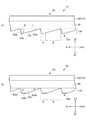
図6は、比較例1,2の導光板73,83の背面側単位光学形状733,833を説明する図である。図6では、比較例1,2の導光板73,83のXZ面に平行な断面の一部を拡大して示しており、図6(a)は、比較例1の導光板73の背面側単位光学形状733を示し、図6(b)は、比較例2の導光板83の背面側単位光学形状833を示している。
比較例1の導光板73及び比較例2の導光板83は、その背面に形成される背面側光学形状部の背面側単位光学形状733,833の形状が、実施例1の導光板とは異なる以外は、実施例1の導光板と同様の形状である。
図6(a)に示すように、比較例1の導光板73の背面側単位光学形状733は、頂面部133cを有しておらず、その断面形状が第1斜面部733a,第2斜面部733bを有する不等辺三角形形状である。第1斜面部733a及び第2斜面部733bが背面73d(XY面に平行な面)となす角度β=45°,γ=0.6°であり、頂角はε=134.4°である。また、背面側単位光学形状733の配列ピッチは、150μmである。
FIG. 6 is a diagram for explaining the rear-side unit optical shapes 733 and 833 of the light guide plates 73 and 83 of the first and second comparative examples. In FIG. 6, a part of a cross section parallel to the XZ plane of the light guide plates 73 and 83 of Comparative Examples 1 and 2 is enlarged, and FIG. 6A shows the back side of the light guide plate 73 of Comparative Example 1. The unit optical shape 733 is shown, and FIG. 6B shows the back-side unit optical shape 833 of the light guide plate 83 of Comparative Example 2.
The light guide plate 73 of the comparative example 1 and the light guide plate 83 of the comparative example 2 are different from the light guide plate of the first embodiment in the shape of the back side unit optical shapes 733 and 833 of the back side optical shape portion formed on the back side. Other than that, it is the same shape as the light guide plate of Example 1.
As shown in FIG. 6A, the back side unit optical shape 733 of the light guide plate 73 of Comparative Example 1 does not have the top surface portion 133c, and the cross-sectional shapes thereof are the first slope portion 733a and the second slope portion. It is an unequal triangular shape having 733b. The angles β = 45 ° and γ = 0.6 ° formed by the first inclined surface portion 733a and the second inclined surface portion 733b and the rear surface 73d (surface parallel to the XY plane), and the apex angle is ε = 13.4.4 °. . The arrangement pitch of the back unit optical shapes 733 is 150 μm.

比較例2の導光板83の背面側単位光学形状833は、頂面部833cと、第1斜面部833a,第2斜面部833bを有し、その断面形状は、台形形状である。この頂面部833cは、背面83d(本実施形態では、XY面)に平行、即ち、角度α=0°である。従って、頂面部833c全体で、反射シート16に接する。第1斜面部833a及び第2斜面部833bが背面73d(XY面に平行な面)となす角度β,γや配列ピッチは、実施例1の背面側単位光学形状の角度β,γ及び配列ピッチP1と同様である。   The rear unit optical shape 833 of the light guide plate 83 of Comparative Example 2 includes a top surface portion 833c, a first inclined surface portion 833a, and a second inclined surface portion 833b, and the cross-sectional shape thereof is a trapezoidal shape. The top surface portion 833c is parallel to the back surface 83d (XY surface in the present embodiment), that is, the angle α = 0 °. Accordingly, the entire top surface portion 833c is in contact with the reflection sheet 16. The angles β, γ and arrangement pitch formed by the first inclined surface portion 833a and the second inclined surface portion 833b with the rear surface 73d (surface parallel to the XY plane) are the angles β, γ and the arrangement pitch of the rear unit optical shape of the first embodiment. Same as P1.

また、特に図示しないが、以下の比較例3の導光板も作製し、評価等を行った。
比較例3の導光板は、背面側単位光学形状の頂面部の角度α=2°(即ち、α>1°)である点等が、実施例1の導光板13とは異なる以外は、実施例1の導光板13と同様の形態である。
Although not particularly shown, a light guide plate of Comparative Example 3 below was also prepared and evaluated.
The light guide plate of Comparative Example 3 is implemented except that the angle α = 2 ° (that is, α> 1 °) of the top surface portion of the back unit optical shape is different from the light guide plate 13 of Example 1. This is the same form as the light guide plate 13 of Example 1.

実施例1,2及び比較例1〜3の導光板を備える各透過型表示装置1を、同一条件下で作成し、所定の時間及び速度等で輸送した後、透過型表示装置の状態で光源部12を点灯して白色表示し、目視により面内輝度分布の均一性を評価した。
また、実施例1,2及び比較例1〜3の導光板を備える各透過型表示装置1を分解し、実施例1,2の導光板13及び比較例1〜3の導光板73,83の背面側単位光学形状133,733,833の破損の状況や、反射シート16の破損の状況等を調べた。
Each transmissive display device 1 including the light guide plates of Examples 1 and 2 and Comparative Examples 1 to 3 is prepared under the same conditions, transported at a predetermined time and speed, etc., and then a light source in the state of the transmissive display device. The part 12 was turned on and displayed in white, and the uniformity of the in-plane luminance distribution was evaluated visually.
Moreover, each transmissive display apparatus 1 provided with the light guide plates of Examples 1 and 2 and Comparative Examples 1 to 3 is disassembled, and the light guide plates 13 of Examples 1 and 2 and the light guide plates 73 and 83 of Comparative Examples 1 to 3 are disassembled. The state of breakage of the rear unit optical shapes 133, 733, and 833, the state of breakage of the reflection sheet 16, and the like were examined.

比較例1の導光板73では、多くの背面側単位光学形状733において、頂点733tに欠けやひび等が生じ、第2斜面部733bの頂点733t側にもひび等の傷が生じていた。また、頂点733tが接する反射シート16の表面には、頂点733tによ引っかき状の傷も多数生じてた。
また、比較例2の導光板83では、多くの背面側単位光学形状833において、頂面部833c自体に引っかき状の傷が多数生じており、頂面部833cの光が入射する領域Bにも傷が生じていた。また、多くの背面側単位光学形状833において、第2斜面部833bの頂面部833c側端部に欠けやひび等が生じていた。
さらに、比較例1,2の導光板73,83を備える透過型表示装置1の光源部12を点灯して白色表示すると、傷付いた部分で拡散反射された光の一部が出光面から出射し、明るく見えるスポットができたり、光源部12から離れた対向面13b側(X2側)の領域の輝度が低下する等の輝度ムラが確認された。
In the light guide plate 73 of the comparative example 1, in many of the back side unit optical shapes 733, the apex 733t was chipped, cracked or the like, and the second inclined surface portion 733b was also scratched or cracked on the apex 733t side. In addition, many scratches were formed on the surface of the reflection sheet 16 with which the vertex 733t was in contact with the vertex 733t.
Further, in the light guide plate 83 of the comparative example 2, in many of the back side unit optical shapes 833, many scratches are generated on the top surface portion 833c itself, and there are also scratches on the region B where the light of the top surface portion 833c is incident. It was happening. Further, in many back-side unit optical shapes 833, chips, cracks, and the like were generated at the end portion on the top surface portion 833c side of the second inclined surface portion 833b.
Further, when the light source unit 12 of the transmissive display device 1 including the light guide plates 73 and 83 of Comparative Examples 1 and 2 is turned on to display white, a part of the light diffusely reflected by the damaged part is emitted from the light exit surface. In addition, brightness unevenness such as a bright spot or a decrease in brightness of the area on the facing surface 13b side (X2 side) away from the light source unit 12 was confirmed.

比較例3の導光板では、角度α=2°であるため、頂面部の光が到達する領域に入射して全反射した後、出光面13cから出射する光の量が増えていた。そのため、導光効率が低下し、特に光源部12近傍が明るくなり、光源部12から離れるにつれて暗くなり、面内輝度分布の均一性が低下し、輝度ムラが生じていた。
ここで、角度γは、導光効率を高め、かつ、出光面13cからの出光量分布の均一性を高める観点から、γ>αを満たしながら、できるだけ小さい方が好ましい。しかし、α>1°である場合、上述のような輝度ムラを低減し、導光効率を高めるような角度γの設計が困難である。
In the light guide plate of Comparative Example 3, since the angle α = 2 °, the amount of light emitted from the light exit surface 13c increased after entering the region where the light on the top surface reaches and totally reflected. For this reason, the light guide efficiency is lowered, particularly in the vicinity of the light source unit 12, and becomes darker with distance from the light source unit 12, the uniformity of the in-plane luminance distribution is reduced, and luminance unevenness occurs.
Here, the angle γ is preferably as small as possible while satisfying γ> α from the viewpoint of improving the light guide efficiency and improving the uniformity of the light output distribution from the light output surface 13c. However, when α> 1 °, it is difficult to design an angle γ that reduces the luminance unevenness as described above and increases the light guide efficiency.

一方、実施例1,2の導光板13では、背面側単位光学形状133の一部に頂点133t近傍の欠けやひび等が生じていたが、光の反射に寄与する領域B内に位置する頂面部133cや第2斜面部133bには、傷等がほとんど生じておらず、また、反射シート16表面の傷つきも大幅に低減されていた。
また、実施例1に比べて実施例2の導光板13方が、接触部となる頂点133tが曲面上に位置しているため、背面側単位光学形状133や反射シート16の傷つきがより低減されていた。
さらに、実施例1,2の導光板13を備える透過型表示装置1を白色表示したところ、輝度ムラや局所的な明るいスポット等は生じておらず、面内輝度分布の均一性が高かった。
On the other hand, in the light guide plate 13 of Examples 1 and 2, chipping or cracking in the vicinity of the apex 133t occurred in a part of the rear unit optical shape 133, but the apex located in the region B that contributes to light reflection. The surface portion 133c and the second inclined surface portion 133b were hardly damaged, and the surface of the reflective sheet 16 was greatly reduced.
Moreover, since the vertex 133t used as the contact part is located on the curved surface of the light guide plate 13 of the second embodiment as compared with the first embodiment, damage to the back side unit optical shape 133 and the reflection sheet 16 is further reduced. It was.
Furthermore, when the transmissive display device 1 including the light guide plate 13 of Examples 1 and 2 was displayed in white, there was no luminance unevenness or local bright spots, and the uniformity of the in-plane luminance distribution was high.

以上のことから、本実施形態によれば、製造作業中等において、背面側単位光学形状133の光が入射する領域Bへの傷付きを大幅に低減でき、導光効率が高く、かつ、輝度ムラのない良好な導光板とすることができる。
また、このような導光板13を備える面光源装置10、透過型表示装置1とすることにより、輝度ムラが大幅に改善され、光の利用効率も高い良好な面光源装置10及び透過型表示装置1とすることができる。
From the above, according to the present embodiment, during manufacturing work or the like, it is possible to greatly reduce the damage to the region B where the light of the rear-side unit optical shape 133 is incident, the light guide efficiency is high, and the luminance unevenness It can be set as the favorable light-guide plate without this.
In addition, by using the surface light source device 10 and the transmissive display device 1 including the light guide plate 13 as described above, a favorable surface light source device 10 and a transmissive display device in which luminance unevenness is significantly improved and light utilization efficiency is high. 1 can be used.

(変形形態)
以上説明した実施形態に限定されることなく、種々の変形や変更が可能であって、それらも本発明の範囲内である。
(1)本実施形態において、出光側単位光学形状131は、その配列ピッチP2と、配列方向における幅W2とが等しい例を示したが、これに限らず、配列ピッチP2が配列方向における幅W2よりも大きく、各出光側単位光学形状131間に、平面部や凹部等が形成された形状としてもよい。
なお、背面側単位光学形状133についても同様である。
(Deformation)
The present invention is not limited to the embodiment described above, and various modifications and changes are possible, and these are also within the scope of the present invention.
(1) In the present embodiment, the light emitting unit optical shape 131 has an example in which the arrangement pitch P2 is equal to the width W2 in the arrangement direction, but the present invention is not limited to this, and the arrangement pitch P2 is the width W2 in the arrangement direction. It is also possible to use a shape in which a flat portion, a concave portion or the like is formed between the light exit side unit optical shapes 131.
The same applies to the rear unit optical shape 133.

(2)本実施形態において、本体部135の厚さが一定であり、導光板13の総厚(Z方向における厚さ)が一定である例を示したが、これに限らず、例えば、出光面13cに直交しかつ背面側単位光学形状133の配列方向に平行な断面(XZ面に平行な断面)において、本体部135の厚さが、入光面13a側が厚く、対向面13b側へ進むにつれて次第に薄くなる形状とし、入光面13a側が厚く、対向面13b側へ進むにつれて次第に薄くなる導光板13としてもよい。このとき、背面13dは、出光面やXY面に平行ではない。なお、このような形状とする場合には、背面側単位光学形状の角度αは、背面13dに平行な面に対してなす角度とする。 (2) In the present embodiment, the example in which the thickness of the main body portion 135 is constant and the total thickness of the light guide plate 13 (thickness in the Z direction) is constant has been described. In a cross section orthogonal to the surface 13c and parallel to the arrangement direction of the back side unit optical shapes 133 (cross section parallel to the XZ plane), the thickness of the main body 135 is thick on the light incident surface 13a side and proceeds toward the facing surface 13b side. The light guide plate 13 may have a shape that gradually becomes thinner as the light incident surface 13a side becomes thicker and the light guide plate 13 gradually becomes thinner toward the opposing surface 13b side. At this time, the back surface 13d is not parallel to the light exit surface or the XY plane. In the case of such a shape, the angle α of the back unit optical shape is an angle formed with respect to a surface parallel to the back surface 13d.

(3)本実施形態において、導光板13に背面側(Z1側)に反射シート16が配置される例を示したが、これに限らず、例えば、反射シートではなく、面光源装置10又は透過型表示装置1の導光板13の背面側に位置する筐体の導光板13側の面に、光反射性を有する塗料や金属箔等を塗付又は転写等して形成してもよい。 (3) In the present embodiment, the example in which the reflection sheet 16 is arranged on the back side (Z1 side) of the light guide plate 13 has been described. However, the present invention is not limited to this. The surface of the housing located on the back side of the light guide plate 13 of the mold display device 1 may be formed by applying or transferring a light-reflecting paint or metal foil.

(4)本実施形態において、面光源装置10は、導光板13よりもLCDパネル11側(観察面側)に、プリズムシート14、光拡散シート15等を備える例を示したが、これに限らず、プリズムシート14と導光板13との間や、プリズムシート14とLCDパネル11との間に、拡散作用を有する光学シートや、各種レンズ形状やプリズム形状が形成された他の光学シート等を組み合わせ配置してもよい。また、面光源装置10は、プリズムシート14以外の偏向作用を有する光学シートを用いてもよい。
使用環境や所望の光学性能に合わせて、面光源装置10として導光板13と組み合わせて用いる各種光学シート等は、適宜選択して用いることができる。
(4) In the present embodiment, the surface light source device 10 has been described as including the prism sheet 14, the light diffusion sheet 15, and the like on the LCD panel 11 side (observation surface side) with respect to the light guide plate 13. First, an optical sheet having a diffusing action, other optical sheets formed with various lens shapes or prism shapes, or the like between the prism sheet 14 and the light guide plate 13 or between the prism sheet 14 and the LCD panel 11. Combinations may be arranged. Further, the surface light source device 10 may use an optical sheet having a deflecting action other than the prism sheet 14.
Various optical sheets used in combination with the light guide plate 13 as the surface light source device 10 can be appropriately selected and used in accordance with the use environment and desired optical performance.

なお、本実施形態及び変形形態は、適宜組み合わせて用いることもできるが、詳細な説明は省略する。また、本発明は以上説明した実施形態によって限定されることはない。   In addition, although this embodiment and modification can also be used in combination as appropriate, detailed description is abbreviate | omitted. Further, the present invention is not limited to the embodiment described above.

1 透過型表示装置
10 面光源装置
11 LCDパネル
12 光源部
13 導光板
131 出光側単位光学形状
133 背面側単位光学形状
13a 入光面
13b 対向面
14 プリズムシート
15 光拡散シート
16 反射シート
DESCRIPTION OF SYMBOLS 1 Transmission type display apparatus 10 Surface light source device 11 LCD panel 12 Light source part 13 Light guide plate 131 Light emission side unit optical shape 133 Back side unit optical shape 13a Light incident surface 13b Opposite surface 14 Prism sheet 15 Light diffusion sheet 16 Reflection sheet

Claims (7)

面光源装置に用いられ、光が入射する入光面と、前記入光面に交差し光が出射する出光面と、前記出光面に対向する背面とを有し、前記入光面から入射した光を、入光面側から前記入光面に対向する対向面側へと向かう導光方向に導光しながら前記出光面から出射する導光板であって、
前記背面に、背面側単位光学形状が前記導光方向に平行に複数配列されて設けられ、
前記背面側単位光学形状は、背面側に凸となる柱状であり、該導光板よりも背面側に位置する部材と接する接触部を有する頂面部と、前記背面側単位光学形状の配列方向において、前記頂面部よりも入光面側に位置する第1斜面部と、対向面側に位置して入射する光の少なくとも一部を全反射する第2斜面部とを有し、
少なくとも前記第1斜面部及び前記接触部は、前記入光面から前記導光方向に進む光が入射しない領域に位置し、
前記背面側単位光学形状の配列方向において、前記頂面部の少なくとも前記第2斜面部に隣接する領域は、その入光面側端部が対向面側端部よりも背面側に位置するように、前記背面に対して、0°<α≦1°を満たす角度αをなすこと、
特徴とする導光板。
Used in a surface light source device, has a light incident surface on which light is incident, a light exit surface that intersects the light incident surface and emits light, and a back surface that faces the light exit surface, and is incident from the light incident surface A light guide plate that emits light from the light exit surface while guiding light in a light guide direction from the light entrance surface toward the opposite surface opposite the light entrance surface ;
On the back side, a plurality of back side unit optical shapes are arranged in parallel to the light guide direction,
The back side unit optical shape is a columnar shape that is convex on the back side, in the arrangement direction of the back side unit optical shape, the top surface portion having a contact portion that contacts a member located on the back side of the light guide plate, has a first inclined surface portion located to the incident surface side of the top wall, and a second slope portion for totally reflecting at least a part of the light incident positioned facing side,
At least the first slope portion and the contact portion are located in a region where light traveling in the light guide direction from the light incident surface is not incident,
In the arrangement direction of the back side unit optical shape, the region adjacent to at least the second slope portion of the top surface portion is such that its light incident surface side end portion is located on the back side with respect to the opposing surface side end portion, An angle α satisfying 0 ° <α ≦ 1 ° with respect to the back surface;
The light guide plate according to claim.
請求項1に記載の導光板において、
前記背面側単位光学形状の間の谷底となる点から前記接触部までの前記背面の法線方向における寸法は、1μm以上50μm以下であること、
を特徴とする導光板。
The light guide plate according to claim 1,
The dimension in the normal direction of the back surface from the point that becomes the valley bottom between the back side unit optical shapes to the contact portion is 1 μm or more and 50 μm or less,
A light guide plate characterized by
請求項1又は請求項2に記載の導光板において、
前記背面側単位光学形状の配列方向における前記光が到達しない領域の幅が、前記背面側単位光学形状の配列ピッチに対する割合は、5%以上であること、
を特徴とする導光板。
In the light guide plate according to claim 1 or 2,
The ratio of the width of the region where the light does not reach in the arrangement direction of the back side unit optical shape is 5% or more with respect to the arrangement pitch of the back side unit optical shape,
A light guide plate characterized by
請求項1から請求項3までのいずれか1項に記載の導光板において、
前記第1斜面部が該導光板の板面となす角度をβ、前記出光面での臨界角をθ、前記第2斜面部が前記板面となす角度γとするとき、角度βは、
(90°−θ)<β、かつ、γ<β
を満たすこと、
を特徴とする導光板。
In the light-guide plate of any one of Claim 1- Claim 3,
When the angle formed by the first inclined surface portion with the plate surface of the light guide plate is β, the critical angle at the light exit surface is θ, and the angle γ formed by the second inclined surface portion with the plate surface, the angle β is:
(90 ° −θ) <β and γ <β
Meeting,
A light guide plate characterized by
請求項1から請求項4までのいずれか1項に記載の導光板において、
前記接触部は、背面側に凸となる曲面上に位置すること、
を特徴とする導光板。
In the light-guide plate of any one of Claim 1- Claim 4,
The contact portion is located on a curved surface that is convex on the back side;
A light guide plate characterized by
請求項1から請求項5までのいずれか1項に記載の導光板と、
前記入光面に対面する位置に設けられ、前記入光面へ光を投射する光源部と、
前記導光板の出光面側に配置され、前記導光板から出射した光を、そのシート面の法線方向又は法線方向となす角度が小さくなる方向へ向ける偏向作用を有する偏向光学シートと、
を備える面光源装置。
The light guide plate according to any one of claims 1 to 5,
A light source unit provided at a position facing the light incident surface and projecting light onto the light incident surface;
A deflecting optical sheet disposed on the light exit surface side of the light guide plate and having a deflection action to direct light emitted from the light guide plate in a direction in which a normal angle of the sheet surface or an angle with the normal direction is reduced;
A surface light source device comprising:
請求項6に記載の面光源装置と、
前記面光源装置によって背面側から照明される透過型表示部と、
を備える透過型表示装置。
A surface light source device according to claim 6;
A transmissive display unit illuminated from the back side by the surface light source device;
A transmissive display device.
JP2012144569A 2012-06-27 2012-06-27 Light guide plate, surface light source device, transmissive display device Active JP5929552B2 (en)

Priority Applications (1)

Application Number Priority Date Filing Date Title
JP2012144569A JP5929552B2 (en) 2012-06-27 2012-06-27 Light guide plate, surface light source device, transmissive display device

Applications Claiming Priority (1)

Application Number Priority Date Filing Date Title
JP2012144569A JP5929552B2 (en) 2012-06-27 2012-06-27 Light guide plate, surface light source device, transmissive display device

Publications (2)

Publication Number Publication Date
JP2014010911A JP2014010911A (en) 2014-01-20
JP5929552B2 true JP5929552B2 (en) 2016-06-08

Family

ID=50107457

Family Applications (1)

Application Number Title Priority Date Filing Date
JP2012144569A Active JP5929552B2 (en) 2012-06-27 2012-06-27 Light guide plate, surface light source device, transmissive display device

Country Status (1)

Country Link
JP (1) JP5929552B2 (en)

Families Citing this family (2)

* Cited by examiner, † Cited by third party
Publication number Priority date Publication date Assignee Title
CN105445844A (en) * 2014-09-02 2016-03-30 深圳Tcl新技术有限公司 Light guide plate, manufacturing method of same, and backlight module
CN114910992B (en) * 2022-04-19 2022-12-13 安徽亿光源光电科技有限公司 High light efficiency type light guide plate

Family Cites Families (6)

* Cited by examiner, † Cited by third party
Publication number Priority date Publication date Assignee Title
JPS6094605U (en) * 1983-12-02 1985-06-27 セイコーエプソン株式会社 Transparent display device
JP3012462B2 (en) * 1994-09-26 2000-02-21 富士通株式会社 Light guide plate, surface light source and non-light emitting display device using the same
JPH09166713A (en) * 1995-10-11 1997-06-24 Mitsubishi Rayon Co Ltd Backlight
JP2001093318A (en) * 1999-09-22 2001-04-06 Sanyo Electric Co Ltd Light guide plate, surface light source device and display
JP2009224316A (en) * 2008-02-19 2009-10-01 Seiko Instruments Inc Illuminating device and liquid crystal display device
JP2011215569A (en) * 2010-03-19 2011-10-27 Hitachi Chem Co Ltd Optical film and surface light source device

Also Published As

Publication number Publication date
JP2014010911A (en) 2014-01-20

Similar Documents

Publication Publication Date Title
JP5919964B2 (en) Light guide plate, surface light source device, display device
JP5765301B2 (en) Light guide plate, surface light source device, transmissive display device
JP2012164583A (en) Light guide plate, surface light source device, and transmission type display device
JP5700084B2 (en) Light guide plate, surface light source device, transmissive display device
JP6354207B2 (en) Reflective sheet, surface light source device, transmissive display device
JP2018106828A (en) Surface light source device, transmissive display device
JP5804216B2 (en) Light guide plate, surface light source device, transmissive display device
JP5929552B2 (en) Light guide plate, surface light source device, transmissive display device
JP5804011B2 (en) Transmission type display device
JP2017208287A (en) Surface light source device, transmissive display device
JP2016134353A (en) Light guide plate, surface light source device, transmissive display device
JP6303649B2 (en) Surface light source device, transmissive display device
JP4730339B2 (en) Surface light source device, transmissive display device
JP5700169B2 (en) Light guide plate, surface light source device, transmissive display device
JP5664609B2 (en) Light guide plate, surface light source device, transmissive display device
JP2017004637A (en) Light guide plate, surface light source device, transmission type display device
JP5935459B2 (en) Light guide plate, surface light source device, display device
JP2015069932A (en) Surface light source device, transmissive display device
JP2008305585A (en) Surface light source device, transmissive display device
JP2008305587A (en) Surface light source device, transmissive display device
JP2015191818A (en) Surface light source device, transmissive display device
JP5679020B1 (en) Light guide plate, surface light source device, transmissive display device
JP2015069764A (en) Reflective sheet, surface light source device, transmissive display device
JP2016134332A (en) Light guide plate, surface light source device, and transmission type display device
JP6020687B1 (en) Light guide plate, surface light source device, transmissive display device

Legal Events

Date Code Title Description
A621 Written request for application examination

Free format text: JAPANESE INTERMEDIATE CODE: A621

Effective date: 20150514

A977 Report on retrieval

Free format text: JAPANESE INTERMEDIATE CODE: A971007

Effective date: 20160127

A131 Notification of reasons for refusal

Free format text: JAPANESE INTERMEDIATE CODE: A131

Effective date: 20160202

A521 Written amendment

Free format text: JAPANESE INTERMEDIATE CODE: A523

Effective date: 20160315

TRDD Decision of grant or rejection written
A01 Written decision to grant a patent or to grant a registration (utility model)

Free format text: JAPANESE INTERMEDIATE CODE: A01

Effective date: 20160405

A61 First payment of annual fees (during grant procedure)

Free format text: JAPANESE INTERMEDIATE CODE: A61

Effective date: 20160418

R150 Certificate of patent or registration of utility model

Ref document number: 5929552

Country of ref document: JP

Free format text: JAPANESE INTERMEDIATE CODE: R150

RD04 Notification of resignation of power of attorney

Free format text: JAPANESE INTERMEDIATE CODE: R3D04