JP5765301B2 - Light guide plate, surface light source device, transmissive display device - Google Patents
Light guide plate, surface light source device, transmissive display device Download PDFInfo
- Publication number
- JP5765301B2 JP5765301B2 JP2012179601A JP2012179601A JP5765301B2 JP 5765301 B2 JP5765301 B2 JP 5765301B2 JP 2012179601 A JP2012179601 A JP 2012179601A JP 2012179601 A JP2012179601 A JP 2012179601A JP 5765301 B2 JP5765301 B2 JP 5765301B2
- Authority
- JP
- Japan
- Prior art keywords
- light
- guide plate
- light guide
- light source
- slope portion
- Prior art date
- Legal status (The legal status is an assumption and is not a legal conclusion. Google has not performed a legal analysis and makes no representation as to the accuracy of the status listed.)
- Active
Links
Images


Description
本発明は、導光板と、これを備える面光源装置、透過型表示装置に関するものである。 The present invention relates to a light guide plate, a surface light source device including the light guide plate, and a transmissive display device.
従来、LCD(Liquid Crystal Display)パネル等の透過型表示部を背面から面光源装置(バックライト)によって照明し、映像を表示する透過型表示装置が知られている。
面光源装置は、大きく分けて、各種光学シート等の光学部材の直下に光源を配置する直下型のものと、光学部材の側面側に光源が配置されるエッジライト型のものがある。このエッジライト型の面光源装置は、光源を導光板等の光学部材の側面側に配置することから、直下型のものに比べて面光源装置をより薄型化できるという利点を有し、近年広く用いられている。
2. Description of the Related Art Conventionally, a transmissive display device that displays an image by illuminating a transmissive display unit such as an LCD (Liquid Crystal Display) panel from the back with a surface light source device (backlight) is known.
Surface light source devices are broadly classified into a direct type in which a light source is arranged directly under an optical member such as various optical sheets and an edge light type in which a light source is arranged on a side surface side of the optical member. This edge light type surface light source device has an advantage that the surface light source device can be made thinner than the direct type since the light source is arranged on the side surface side of the optical member such as a light guide plate. It is used.
一般的に、エッジライト型の面光源装置では、導光板の側面である入光面に対面する位置に光源が配置されており、光源が発する光は、入光面から導光板に入射し、出光面とこれに対向する背面とで反射を繰り返しながら、入光面に略直交する方向(導光方向)へ進む。
そして、導光板の背面に設けられた拡散パターン等によって光の進行方向を変化させることにより、出光面の導光方向に沿った各位置から少しずつ光がLCDパネル側へ出光していく(例えば、特許文献1,2参照)。
Generally, in an edge light type surface light source device, a light source is disposed at a position facing a light incident surface that is a side surface of a light guide plate, and light emitted from the light source enters the light guide plate from the light incident surface, While repeating reflection at the light exit surface and the back surface opposite to the light exit surface, the light travels in a direction substantially perpendicular to the light entrance surface (light guide direction).
Then, by changing the traveling direction of the light by a diffusion pattern or the like provided on the back surface of the light guide plate, light is emitted little by little from each position along the light guide direction of the light exit surface to the LCD panel side (for example, Patent Documents 1 and 2).
例えば、特許文献1,2に示すような背面に拡散パターンを有する導光板を用いた場合には、光が背面の拡散パターンによって拡散反射されて出光するため、光の収束性が低下し、正面輝度が低下するという問題がある。また、このような導光板を用いた場合には、導光方向以外の方向にも光が拡散反射されるため、導光効率が低下し、導光方向において光源から遠い側が暗くなるという問題が生じる場合がある。
そのため、近年では、背面にプリズム形状等が複数形成された導光板が広く用いられるようになってきている。このような導光板は、光を拡散反射しないので、正面輝度を高くすることができ、また、導光方向において、光源から離れた領域であっても、十分に導光することができ、光の均一性も良好である。
For example, when using a light guide plate having a diffusion pattern on the back surface as shown in Patent Documents 1 and 2, the light is diffused and reflected by the diffusion pattern on the back surface, and thus the light convergence is reduced, and the front surface is reduced. There is a problem that the luminance is lowered. In addition, when such a light guide plate is used, light is diffusely reflected in directions other than the light guide direction, so that the light guide efficiency is lowered and the side far from the light source in the light guide direction is dark. May occur.
Therefore, in recent years, a light guide plate having a plurality of prism shapes and the like formed on the back surface has been widely used. Since such a light guide plate does not diffusely reflect light, the front luminance can be increased, and even in a region away from the light source in the light guide direction, light can be sufficiently guided, The uniformity is also good.
このような背面側にプリズム形状を有する導光板において、導光効率を向上させ、かつ、光の取り出し効率を向上させるために、光源側(入光面側)から離れるにつれてピッチを大きくし、1つのプリズム形状において光が入射する斜面部分を大きく形成しているものがある。このような導光板では、他の光学シート等との干渉によるもの以外にも、導光板のプリズム形状の配列ピッチの変化等に起因するモアレ(所謂、自己モアレ)が生じるという問題があった。
このモアレは、入光面側(光源側)から離れ、配列ピッチが大きくなるにつれて顕著に視認される傾向を有し、また、特に、モアレとして明暗縞が生じた場合には、導光板の出射側に複数の光学シート等を配置しても解消されにくいという問題があった。
In such a light guide plate having a prism shape on the back side, in order to improve light guide efficiency and improve light extraction efficiency, the pitch is increased as the distance from the light source side (light incident surface side) increases. In some prism shapes, a slope portion on which light is incident is greatly formed. In such a light guide plate, there is a problem that moire (so-called self moire) is caused due to a change in the arrangement pitch of prism shapes of the light guide plate in addition to interference with other optical sheets.
This moire has a tendency to be noticed as the arrangement pitch increases with increasing distance from the light incident surface side (light source side). In particular, when light and dark stripes occur as moire, the light is emitted from the light guide plate. There is a problem that even if a plurality of optical sheets and the like are arranged on the side, it is difficult to be solved.
本発明の課題は、モアレを大幅に改善でき、明るさの面内均一性が高い、良好な導光板、及び、これを備える面光源装置、透過型表示装置を提供することである。 An object of the present invention is to provide a good light guide plate that can greatly improve moire and has high in-plane brightness uniformity, and a surface light source device and a transmissive display device including the same.
本発明は、以下のような解決手段により、前記課題を解決する。なお、理解を容易にするために、本発明の実施形態に対応する符号を付して説明するが、これに限定されるものではない。
請求項1の発明は、光源部からの光が入射する入光面(13a,23a,23b)と、光が出射する出光面(13c)と、出光面に対向する背面(13d,23d)とを備える導光板であって、前記背面には、光の導光方向に略平行な方向を配列方向として背面側単位光学形状(133,233)が互いに隣接して複数配列され、前記背面側単位光学形状は、背面側に凸となる略四角柱形状であり、頂面部(133c,233c)と、前記頂面部を挟んで対向する位置に形成される側面である第1斜面部(133a,233a)及び第2斜面部(133b,233b)を有し、前記配列方向における前記背面側単位光学形状の配列ピッチをP1とし、配列方向における前記頂面部の寸法をWcとするとき、前記配列ピッチは一定であり、前記配列方向において、前記入光面から離れるにつれて、比Wc/P1が小さくなり、前記頂面部(133c,233c)が、前記配列方向において前記背面(13d)となす角度をγとし、前記第1斜面部(133a,233a)及び前記第2斜面部(133b,233a)のうち、前記配列方向において前記入光面に対向する斜面部(133b,233a,233b)が前記配列方向において前記背面となす角度をβとするとき、βは一定であり、0°≦γ≦0.5°、1°≦β≦5°という関係を満たすこと、を特徴とする導光板(13,23)である。
請求項2の発明は、請求項1に記載の導光板において、前記第1斜面部(133a,233a)及び前記第2斜面部(133b,233b)のうち、前記配列方向において前記入光面に対向する斜面部(133b,233a,233b)の前記配列方向の寸法をWdとするとき、比Wd/P1は、0.05≦Wd/P1≦0.95という関係を満たすこと、を特徴とする導光板(13,23)である。
請求項3の発明は、請求項1又は請求項2に記載の導光板において、前記背面を法線方向から見たときに、前記第1斜面(133a,233a)部及び前記第2斜面部(133b,233b)のうち、前記配列方向において前記入光面に対向する斜面部(133b,233a,233b)が占める総面積をM1とし、前記背面をその法線方向から見たときの面積をM0とするとき、比M1/M0は、0.4≦M1/M0≦0.6という関係を満たすこと、を特徴とする導光板(13,23)である。
The present invention solves the above problems by the following means. In addition, in order to make an understanding easy, although the code | symbol corresponding to embodiment of this invention is attached | subjected and demonstrated, it is not limited to this.
According to the first aspect of the present invention, a light incident surface (13a, 23a, 23b) on which light from the light source part enters, a light outgoing surface (13c) from which light is emitted, and a back surface (13d, 23d) facing the light outgoing surface. A plurality of back side unit optical shapes (133, 233) are arranged adjacent to each other with the direction substantially parallel to the light guiding direction being arranged in the back side, and the back side unit is provided on the back side. The optical shape is a substantially quadrangular prism shape that is convex on the back surface side, and the first slope portion (133a, 233a) that is a side surface formed at a position facing the top surface portion (133c, 233c) across the top surface portion. ) And a second inclined surface portion (133b, 233b), the arrangement pitch of the back side unit optical shapes in the arrangement direction is P1, and the dimension of the top surface portion in the arrangement direction is Wc, the arrangement pitch is Constant and said In the column direction, the ratio Wc / P1 decreases as the distance from the light incident surface increases, and the angle between the top surface portion (133c, 233c) and the back surface (13d) in the arrangement direction is γ, and the first inclined surface The angle formed between the slope (133b, 233a, 233b) facing the light incident surface in the arrangement direction and the back in the arrangement direction among the parts (133a, 233a) and the second slope (133b, 233a) Is a light guide plate (13, 23) characterized in that β is constant and satisfies the relationship of 0 ° ≦ γ ≦ 0.5 ° and 1 ° ≦ β ≦ 5 °.
According to a second aspect of the present invention, in the light guide plate according to the first aspect, of the first inclined surface portions (133a, 233a) and the second inclined surface portions (133b, 233b), the light incident surface has the light incident surface in the arrangement direction. The ratio Wd / P1 satisfies the relationship of 0.05 ≦ Wd / P1 ≦ 0.95, where Wd is the dimension in the arrangement direction of the opposing slope portions (133b, 233a, 233b). Light guide plates (13, 23).
According to a third aspect of the present invention, in the light guide plate according to the first or second aspect, the first slope (133a, 233a) and the second slope ( 133b, 233b), the total area occupied by the slopes (133b, 233a, 233b) facing the light incident surface in the arrangement direction is M1, and the area when the back is viewed from the normal direction is M0. The ratio M1 / M0 is the light guide plate (13, 23) characterized by satisfying the relationship of 0.4 ≦ M1 / M0 ≦ 0.6.
請求項4の発明は、請求項1から請求項3までのいずれか1項に記載の導光板(13,23)と、前記入光面(13a,23a,23b)へ入射する光を発する光源部(12,22A,22B)と、前記導光板からの光を正面方向又は正面方向となす角度が小さい方向へ向ける偏向光学シート(14)と、を備える面光源装置(10,20)である。
請求項5の発明は、請求項4に記載の面光源装置(10)において、前記光源部(12)は1つであり、前記背面側単位光学形状(133)内において、前記第1斜面部(133a)が前記入光面(13a)側に位置し、前記第1斜面部は、前記背面(13d)となす角度が前記導光板と空気との界面における臨界角(θ)以上であり、前記光源部から導光する光が入射しないこと、を特徴とする面光源装置(10)である。
請求項6の発明は、請求項4に記載の面光源装置において、前記光源部(22A,22B)は、2つであり、前記導光板(23)の互いに対向する両側面である前記入光面(23a,23b)に面する位置に設けられ、前記第1斜面部(233a)が前記背面(23d)となす角度と、前記第2斜面部(233b)が前記背面となす角度(β)とは、等しいこと、を特徴とする面光源装置(20)である。
請求項7の発明は、請求項4から請求項6までのいずれか1項に記載の面光源装置(10,20)と、前記面光源装置に背面側から照明される透過型表示部(11)と、を備える透過型表示装置(1,2)である。
The invention of claim 4 is a light source that emits light incident on the light guide plate (13, 23) according to any one of claims 1 to 3 and the light incident surface (13a, 23a, 23b). A surface light source device (10, 20) comprising a portion (12, 22A, 22B) and a deflecting optical sheet (14) for directing light from the light guide plate in a front direction or a direction having a small angle with the front direction. .
According to a fifth aspect of the present invention, in the surface light source device (10) according to the fourth aspect of the present invention, the number of the light source sections (12) is one, and the first inclined surface section is formed in the rear unit optical shape (133). (133a) is located on the light incident surface (13a) side, and the first slope portion has an angle formed with the back surface (13d) equal to or greater than a critical angle (θ) at the interface between the light guide plate and air, The surface light source device (10) is characterized in that light guided from the light source section does not enter.
According to a sixth aspect of the present invention, in the surface light source device according to the fourth aspect, the number of the light source portions (22A, 22B) is two, and the light incident light is the opposite side surfaces of the light guide plate (23). Provided at a position facing the surfaces (23a, 23b), an angle formed by the first inclined surface portion (233a) with the back surface (23d) and an angle formed by the second inclined surface portion (233b) with the back surface (β) Is a surface light source device (20) characterized by being equal.
According to a seventh aspect of the present invention, there is provided the surface light source device (10, 20) according to any one of the fourth to sixth aspects, and a transmissive display unit (11) illuminated from the back side of the surface light source device. And a transmissive display device (1, 2).
本発明によれば、モアレを大幅に改善でき、明るさの面内均一性が高い、良好な導光板、及び、これを備える面光源装置、透過型表示装置という効果を奏することができる。 According to the present invention, it is possible to significantly improve moire and to achieve the effects of a good light guide plate having high brightness in-plane uniformity, a surface light source device including the same, and a transmissive display device.
以下、図面等を参照して、本発明の実施形態について説明する。
なお、図1を含め、以下に示す各図は、模式的に示した図であり、各部の大きさ、形状は、理解を容易にするために、適宜誇張している。
また、板、シート等の言葉を使用しているが、これらは、一般的な使い方として、厚さの厚い順に、板、シート、フィルムの順で使用されており、本明細書中でもそれに倣って使用している。しかし、このような使い分けには、技術的な意味は無いので、これらの文言は、適宜置き換えることができるものとする。
さらに、本明細書中において、板面やシート面とは、各板材やシートにおいて、その板やシート全体として見たときにおける、板やシートの平面方向となる面を示すものであるとする。
Embodiments of the present invention will be described below with reference to the drawings.
In addition, each figure shown below including FIG. 1 is the figure shown typically, and the magnitude | size and shape of each part are exaggerated suitably for easy understanding.
In addition, words such as plate and sheet are used, but these are generally used in the order of thickness, plate, sheet, and film in order of increasing thickness. I am using it. However, there is no technical meaning in such proper use, so these terms can be replaced as appropriate.
Further, in the present specification, the plate surface and the sheet surface indicate surfaces in the planar direction of the plate and the sheet when viewed as the entire plate and the sheet in each plate material and sheet.
本明細書中において、形状や幾何学的条件を特定する用語、例えば、平行や直交等の用語については、厳密に意味するところに加え、同様の光学的機能を奏し、平行や直交と見なせる程度の誤差を有する状態も含むものとする。
また、本明細書中に記載する各部材の寸法等の数値及び材料名等は、実施形態としての一例であり、これに限定されるものではなく、適宜選択して使用してよい。
In this specification, terms that specify shape and geometric conditions, for example, terms such as parallel and orthogonal, are strictly meanings, have similar optical functions, and can be regarded as parallel and orthogonal It also includes a state having an error of.
In addition, the numerical values such as the dimensions of the respective members and the material names described in the present specification are examples of the embodiment, and are not limited thereto, and may be appropriately selected and used.
(第1実施形態)
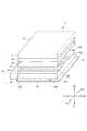
図1は、第1実施形態の透過型表示装置1を説明する図である。
本実施形態の透過型表示装置1は、LCDパネル11と面光源装置10とを備えている。透過型表示装置1は、LCDパネル11を背面側から面光源装置10で照明し、LCDパネル11に形成される映像情報を表示する。
なお、図1を含め以下の図中及び以下の説明において、理解を容易にするために、透過型表示装置1の使用状態において、透過型表示装置1の画面に平行であって互いに直交する2方向をX方向(X1−X2方向)、Y方向(Y1−Y2方向)とし、透過型表示装置1の画面に直交する方向をZ方向(Z1−Z2方向)とする。なお、Z方向においてZ1側が背面側であり、Z2側は観察者側である。
本実施形態の透過型表示装置1の画面は、LCDパネル11の最も観察者側の面(以下、表示面という)11aに相当する。また、透過型表示装置1の「正面方向」とは、この表示面11aの法線方向であり、Z方向に平行であり、後述するプリズムシート14や光拡散シートのシート面や、導光板13の板面等への法線方向と一致するものとする。
(First embodiment)
FIG. 1 is a diagram illustrating a transmissive display device 1 according to the first embodiment.
The transmissive display device 1 of the present embodiment includes an
In addition, in the following drawings including FIG. 1 and the following description, in order to facilitate understanding, when the transmissive display device 1 is in use, the transmissive display device 1 is parallel to the screen of the transmissive display device 1 and orthogonal to each other. The directions are the X direction (X1-X2 direction) and the Y direction (Y1-Y2 direction), and the direction orthogonal to the screen of the transmissive display device 1 is the Z direction (Z1-Z2 direction). In the Z direction, the Z1 side is the back side, and the Z2 side is the observer side.
The screen of the transmissive display device 1 according to the present embodiment corresponds to the surface (hereinafter referred to as a display surface) 11a closest to the viewer of the
LCDパネル11は、透過型の液晶表示素子により形成され、その表示面に映像情報を形成する透過型表示部である。
本実施形態のLCDパネル11は、略平板状であり、LCDパネル11の外形及び表示面11aは、Z方向から見て矩形形状である。そして、LCDパネル11は、Z方向から見て、X方向に平行な対向する2辺と、Y方向に平行な対向する2辺とを有している。
The
The
面光源装置10は、LCDパネル11を背面側から照明する装置であり、光源部12、導光板13、プリズムシート14、光拡散シート15、反射シート16を備えている。この面光源装置10は、所謂、エッジライト型の面光源装置(バックライト)である。この面光源装置10を構成する導光板13、プリズムシート14、光拡散シート15、反射シート16等は、Z方向(正面方向)から見て矩形形状であり、X方向に平行な対向する2辺と、Y方向に平行な対向する2辺とを有している。
The surface
光源部12は、LCDパネル11を照明する光を発する部分である。
本実施形態の光源部12は、導光板13のX方向の一方(X1側)の端面である入光面13aに対面する位置に設けられ、複数の点光源121がY方向に沿って所定の間隔で複数配列されて形成されている。
また、本実施形態の点光源121は、LED(Light Emitting Diode)光源を用いている。なお、光源部12は、例えば、冷陰極管等の線光源としてもよいし、Y方向に延在するライトガイドの端面に光源を配置した形態としてもよい。また、光源部12の発する光の利用効率を向上させる観点から、光源部12の外側を覆うように不図示の反射板を設けてもよい。
The
The
In addition, the point
導光板13は、光を導光する略平板状の部材である。
この導光板13は、入光面13aと、これに対向する対向面13bと、出光面13cとこれに対向する背面13dとを有している。
入光面13a及び対向面13bは、導光板13のX方向の両端部(X1側、X2側)に位置し、板面の法線方向(Z方向)から見て、Y方向に延在している。この入光面13a及び対向面13bは、Y方向及びZ方向に平行であり、X方向に直交している。
導光板13の板面は、XY面に平行であり、本実施形態では、出光面13c及び背面13dは、この板面に平行な面であるとする。
この導光板13は、光源部12からの光を入光面13aから入射させ、出光面13cと背面13dとで全反射させながら、入光面13aに対向する対向面13b側(X2側)へ、主としてX方向に導光し、出光面13cからプリズムシート14側(Z2側)へ適宜出射させる。
The
The
The
The plate surface of the
The
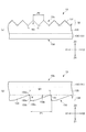
図2は、第1実施形態の導光板13の形状を説明する図である。図2(a)は、出光側単位光学形状131を説明する図であり、図2(b)は、背面側単位光学形状133を説明する図である。図2(a)では、導光板13のYZ面に平行な断面の一部を拡大して示し、図2(b)では、導光板13のXZ面に平行な断面の一部を拡大して示している。
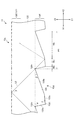
図3は、第1実施形態の背面側単位光学形状133を説明する図である。図3では、図2(b)に示す導光板13のXZ面に平行な断面の一部をさらに拡大して示している。
導光板13は、図2に示すように、導光板13の出光面13cには、出光側単位光学形状131が複数配列して形成される出光側光学形状部132を有し、背面13dには、背面側単位光学形状133が複数配列されて形成される背面側光学形状部134を有している。また、導光板13は、その厚み方向(Z方向)において、出光側光学形状部132と背面側光学形状部134との間に、単位光学形状等が形成されていない略平板状の部分である本体部135を有している。この本体部135と出光側光学形状部132と背面側光学形状部134とは、一体に形成されている。
本実施形態の本体部135は、X方向及びY方向において、その厚さが一定である。
FIG. 2 is a diagram illustrating the shape of the
FIG. 3 is a diagram illustrating the back-side unit
As shown in FIG. 2, the
The
出光側光学形状部132は、導光板13の出光面13cに設けられ、出光側単位光学形状131が複数配列されて形成されている。
出光側単位光学形状131は、図1及び図2(a)に示すように、出光側(Z2側)に凸となる柱状であり、長手方向(稜線方向)をX方向とし、Y方向に複数配列されている。
図2(a)では、本実施形態の出光側単位光学形状131として、三角柱状であり、YZ面に平行な断面形状が頂角δとする二等辺三角形形状である例を挙げて説明する。なお、出光側単位光学形状131は、上記の例に限らず、例えば、五角柱形状等の多角柱形状としてもよいし、楕円柱の一部形状としてもよいし、円柱の一部形状としてもよいし、複数種類の曲面や平面を組み合わせてなる形状としてもよい。
この出光側単位光学形状131の配列ピッチは、P2であり、配列ピッチP2は、出光側単位光学形状131の配列方向の幅W2に等しい(P2=W2)形態となっている。
The light output side
As shown in FIG. 1 and FIG. 2A, the light output side unit
In FIG. 2A, the light output side unit
The arrangement pitch of the light emission side unit
出光側単位光学形状131は、正面方向から見て、導光板13の光の導光方向(X方向)に直交する方向(Y方向)に配列されており、出光面13cから出射する光に対して、その配列方向における光線制御作用を有する。従って、出光側光学形状部132により、導光板13からの出射光のY方向における明るさの均一性や収束性を向上させることができる。なお、このような光線制御作用を必要としない場合には、出光面13cに出光側光学形状部132を形成せず、平面状等としてもよい。
The light exit side unit
背面側光学形状部134は、導光板13の背面13dに設けられ、背面側単位光学形状133が複数配列されて形成されている。
背面側単位光学形状133は、図1,図2(b),図3に示すように、背面側(Z1側)に凸となる四角柱形状であり、長手方向(稜線方向)をY方向とし、導光方向となるX方向に、互いに隣接して複数配列されている。
背面側単位光学形状133は、図2(b)に示すように、XZ面に平行な断面における断面形状が略台形状であり、入光面13a側(X1側)に位置する第1斜面部133aと、頂面部133cよりも対向面13b側(X2側)に位置し、入射する光の少なくとも一部を全反射する第2斜面部133bと、第1斜面部133a及び第2斜面部133bとの間に位置し、最も背面側(Z1側)となる頂面部133cとを有している。
この背面側単位光学形状133の配列ピッチは、P1であり、配列ピッチP1は、背面側単位光学形状133の配列方向の幅W1に等しい(P1=W1)形態となっている。配列ピッチP1は、背面側単位光学形状133の配列方向(X方向)において、一定である。
また、背面側単位光学形状133の高さ(頂点133tから谷底となる点133vまでの寸法)は、H1である。
The back side
The back-side unit
As shown in FIG. 2B, the back unit
The arrangement pitch of the back-side unit
Further, the height (the dimension from the
第1斜面部133aは、導光板13の板面(本実施形態では、XY面に平行な面)と角度αをなし、第2斜面部133bは、導光板13の板面と角度βをなしている。本実施形態の角度α,βは、β<αとなっている。
第1斜面部133aと導光板13の板面とがなす角度αは、図3に示す断面において、導光板13と空気との界面となる出光面13c(XY面に平行な面)における臨界角をθとするとき、(90°−θ)<αを満たしている。従って、入光面13aから対向面13b側へ(X1側からX2側へ)導光する光のうち、出光面13cで全反射して背面側単位光学形状133の間の谷底となる点133vを通って背面側へ進む光L0は、第1斜面部133aには入射しない形態となっている。
また、第2斜面部133bは、背面側単位光学形状133の配列方向(入光面13aから入射した光の導光方向、X方向)において、入光面13aに対向する(入光面13a側とは反対側に位置する)斜面部であり、導光方向に進む光の一部が入射し、かつ、その入射した光の少なくとも一部を全反射する。この角度βは、光の導光効率及び取り出し効率の双方を向上させる観点から、1°≦β≦5°を満たすことが好ましい。
The first
The angle α formed by the first
The second
頂面部133cは、入光面13a側(第1斜面部133a側)端部が対向面13b側(第2斜面部133b側)端部よりも背面側(Z1側)となるように、背面側単位光学形状133の配列方向において、図3に示すように、導光板13の背面13d(XY面に平行な面)に対して角度γをなしている。この角度γは、0°≦γ≦0.5°を満たすことが好ましい。
また、頂面部133cの背面側単位光学形状133の配列方向(X方向)における寸法は、Wcである。この寸法Wcは、背面側単位光学形状233の配列方向において、入光面13aから対向面13bに向かうにつれて、次第に小さくなっている。なお、これに限らず、寸法Wcは、段階的に小さくなる形態としてもよい。
この頂面部133cに入射した光は、全反射し、その進行方向が導光板13の板面(XY面)とその光の進行方向とがなす角度は、殆ど変化しない。従って、頂面部133cを設けることにより、設けないものに比べて、光の導光効率を向上させることができる。
本実施形態では、頂面部133cは、平面状であり、導光板13の板面に対して角度γ=0°である例を挙げて説明する。
The
Moreover, the dimension in the arrangement | sequence direction (X direction) of the back side unit
The light incident on the
In the present embodiment, the
ここで、角度β,γの好ましい範囲について説明する。
角度γが、γ>0.5°となる場合や、角度βが、β<1°である場合、その双方である場合には、頂面部133cと第2斜面部133bとの傾斜角度の差が小さくなる。そのため、後述するような頂面部133cと第2斜面部133b(本実施形態において、背面側単位光学形状133の配列方向(光の導光方向)において入光面13aに対向する斜面部であり、導光する光の一部が入射して全反射する斜面部)との配列方向における寸法の比を変化させたとしても、X方向における任意の点での出光面13cからの光の出光率を十分最適化することができない。従って、光源部12近傍は明るいが、光源部12から離れるにつれて暗くなる輝度ムラが生じ、明るさの面内均一性が低下する。
また、β>5°である場合には、導光方向(X方向)に進む光が第2斜面部133bで全反射したとき、光の進行方向と出光面13c(XY面に平行な面)とがなす角度の全反射前後での変化量は、大きくなる。そのため、導光板13の出光面13cからの出射光の出射角度分布の収束性が低下し、後述するプリズムシート14等による偏向作用を受けても、十分に収束されず、正面輝度が低下する。
以上のことから、角度β,γは、上述の範囲とすることが好ましい。
Here, a preferable range of the angles β and γ will be described.
When the angle γ is γ> 0.5 °, or when the angle β is β <1 °, or both, the difference in inclination angle between the
Further, when β> 5 °, when the light traveling in the light guide direction (X direction) is totally reflected by the second
From the above, it is preferable that the angles β and γ are in the above-described ranges.
また、第1斜面部133a、第2斜面部133b、頂面部133cの背面側単位光学形状の配列方向(X方向)における寸法は、それぞれ、Wa,Wb,Wcである(図3参照)。従って、P1=Wa+Wb+Wcという関係が満たされている。
背面側単位光学形状133の配列方向における頂面部133cの寸法Wcと、配列ピッチP1との比Wc/P1は、0.05≦Wc/P1≦0.95を満たすことが好ましい。
Wc/P1<0.05となる場合には、1つの背面側単位光学形状133において、光を出光面13c側へ反射する頂面部133cの占める割合が小さくなり、第1斜面部133aや第2斜面部133bが占める割合が大きくなりすぎる。そのため、それ以上、比Wc/P1をの値を小さくしても、導光板13の出光面13cから出射する光量の変化率が小さく、導光効率や光の取り出し効率等に有意的な効果が得られないうえに、そのような比率を満たす配列ピッチの設計や、金型の切削加工が困難となり、好ましくない。
Further, the dimensions of the first
The ratio Wc / P1 between the dimension Wc of the
When Wc / P1 <0.05, the proportion of the
また、Wc/P1>0.95となる場合には、1つの背面側単位光学形状133において、頂面部133cの占める割合が大きくなりすぎ、第2斜面部133bが占める割合が小さくなりすぎる。そのため、第2斜面部133bに入射する光量が減り、光の取り出し効率が低下して出光面13cから出射する光量が減り、好ましくない。
従って、比Wc/P1は、0.05≦Wc/P1≦0.95を満たすことが好ましい。
Further, when Wc / P1> 0.95, in one back-side unit
Therefore, the ratio Wc / P1 preferably satisfies 0.05 ≦ Wc / P1 ≦ 0.95.
次に、背面側単位光学形状133の配列方向(X方向)における入光面に対向する斜面部(即ち、第2斜面部133b)の寸法をWdとするとき、この寸法Wd(本実施形態では、Wd=Wb)と、配列ピッチP1との比Wd/P1は、0.05≦Wd/P1≦0.95を満たすことが好ましい。
Wd/P1<0.05となる場合には、1つの背面側単位光学形状133において、光を出光面13c側へ反射する第2斜面部133bの占める割合が小さくなりすぎる。そのため、第2斜面部133bに入射する光量が減り、光の取り出し効率が低下して出光面13cから出射する光量が減り、好ましくない。
Wd/P1>0.95となる場合には、1つの背面側単位光学形状133において、第2斜面部133bが占める割合が大きくなるが、それ以上、比Wd/P1の値を大きくしても、導光板13の出光面13cから出射する光量の変化率が小さく、導光効率や光の取り出し効率等に有意的な効果が得られない。
従って、比Wd/P1は、0.05≦Wd/P1≦0.95を満たすことが好ましい。
Next, when the dimension of the slope part (that is, the
When Wd / P1 <0.05, the proportion of the second
When Wd / P1> 0.95, the proportion of the second
Therefore, the ratio Wd / P1 preferably satisfies 0.05 ≦ Wd / P1 ≦ 0.95.
また、背面側光学形状部134を正面方向(Z方向)から見たとき、背面側単位光学形状133の配列方向(光の導光方向、X方向)において入光面13aに対向する斜面部である第2斜面部133bが占める総面積をM1とし、正面方向から見た背面13dの面積をM0とするとき、面積比M1/M0は、0.4≦M1/M0≦0.6を満たすことが好ましい。
M1/M0<0.4となる場合、第2斜面部133bが占める総面積M1が小さいために、導光板13の出光面13c全面から出射する光の量が低減し、輝度が低減する。また、この場合、第2斜面部133bが占める総面積M1が小さいために、効率よく光を出射させるためには、第2斜面部133bの角度βを大きくしなければならなくなる。そのため、導光板13からの出射光のX方向における出射角度分布の収束性が低下し、後述するプリズムシート14等による偏向作用を受けても、十分に収束されず、正面輝度が低下する。
M1/M0>0.6となる場合、第2斜面部133bが占める総面積が大きくなりすぎ、光を導光するために必要な頂面部133cの面積を十分取れず、また、比Wd/P1を変化させて、X方向における任意の点での出光面13cからの光の出光率を十分最適化することが困難となる。
従って、比M1/M0は、上記範囲を満たすことが好ましい。
Further, when the back surface side
When M1 / M0 <0.4, since the total area M1 occupied by the second
When M1 / M0> 0.6, the total area occupied by the
Therefore, the ratio M1 / M0 preferably satisfies the above range.
本実施形態の導光板13は、例えば、以下のような製造方法で製造可能である。
出光側光学形状部132及び背面側光学形状部134と本体部135とを熱可塑性樹脂により一体に射出成形したり、キャスト成形したり、押し出し成形してもよい。
また、出光側光学形状部132及び背面側光学形状部134と本体部135とを別々に押し出し成形等で形成し、不図示の接着剤等によって一体に接合してもよい。このとき、接着剤と、出光側光学形状部132、背面側光学形状部134、本体部135とは、同じ屈折率とすることが好ましいが、同等と見なせる程度にわずかに屈折率を有していてもよい。
さらに、本体部135を押し出し成形等により形成し、その一方の面に出光側光学形状部132を、他方の面に背面側光学形状部134を、それぞれ電離放射線硬化型樹脂によって形成してもよい。
導光板13の製造方法は、上記の例に限らず、適宜選択して用いてよい。
The
The light output side
Alternatively, the light output side
Further, the
The manufacturing method of the
導光板13に使用される熱可塑性樹脂としては、例えば、アクリル系樹脂や、PC(ポリカーボネート)樹脂、COP(シクロオレフィンポリマー)樹脂、アクリロニトリル系樹脂、ポリオレフィン系樹脂等が挙げられる。また、使用される電離放射線硬化型樹脂としては、例えば、ウレタンアクリレートやエポキシアクリレート等のアクリル系紫外線硬化型樹脂等が挙げられる。
なお、上述の材料に限らず、例えば、ガラス等を用いてもよい。
Examples of the thermoplastic resin used for the
In addition, not only the above-mentioned material but glass etc. may be used, for example.
図1に戻って、面光源装置10の導光板13の背面側(Z1側)には、光を反射する平板状の反射シート16が設けられている。
反射シート16は、導光板13からZ1側へ向かう光を反射して、導光板13内へ向ける機能を有している。
反射シート16は、正面輝度を高める観点から、主として鏡面反射性(正反射性)を有するものが好ましい。反射シート16は、例えば、少なくとも反射面(導光板13側の面)が金属等の高い反射率を有する材料により形成されたシート状の部材、高い反射率を有する材料により形成された薄膜(例えば金属薄膜)を表面層として含んだシート状の部材等を用いることができる。なお、これに限らず、例えば、主として拡散反射性を有し、反射率の高い白色の樹脂シート等としてもよい。
Returning to FIG. 1, a
The
From the viewpoint of increasing the front luminance, it is preferable that the
図4は、プリズムシート14を説明する図である。図4では、プリズムシート14のXZ面に平行な断面の一部を拡大して示している。
プリズムシート14は、導光板13よりもLCDパネル11側(Z2側)に配置されている(図1参照)。このプリズムシート14は、導光板13の出光面13cから出射した光の進行方向を、正面方向(Z方向)、又は、Z方向となす角度が小さい方向へ偏向(集光)する作用を有する偏向光学シートである。
プリズムシート14は、プリズム基材層142と、プリズム基材層142の導光板13側(Z1側)に複数配列されて形成された単位プリズム141とを有している。
FIG. 4 is a diagram illustrating the
The
The
プリズム基材層142は、プリズムシート14のベース(基材)となる部分である。
単位プリズム141は、導光板13側(Z1側)に凸となる三角柱形状であり、プリズム基材層142の背面側(Z1側)の面に、長手方向(稜線方向)をY方向とし、X方向に複数配列されている。即ち、透過型表示装置1の表示面の法線方向(Z方向)から見て、単位プリズム141の配列方向は、導光板13の出光側単位光学形状131の配列方向と直交し、背面側単位光学形状133の配列方向に平行となっている。
The prism
The
本実施形態の単位プリズム141は、その断面形状が頂角εとする二等辺三角形形状である例を示しているが、これに限らず、断面形状を不等辺三角形形状としてもよい。また、単位プリズム141は、少なくとも一方の面が複数の面からなる折れ面状となっていてもよいし、曲面と平面とを組み合わせた形状としてもよいし、断面形状が配列方向において非対称な形状としてもよい。
また、本実施形態の単位プリズム141は、配列ピッチがP4、配列方向の幅がW4であり、配列ピッチと配列方向のレンズ幅が等しい(P4=W4)形状となっている。
プリズムシート14は、図4に示すように、導光板13から出射し、一方の斜面141aから入射した光L1を他方の斜面141bで全反射させることにより、その進行方向を正面方向(Z方向)又は正面方向に対してなす角度が小さくなる方向へ偏向(集光)する。
The
In addition, the
As shown in FIG. 4, the
本実施形態のプリズムシート14は、例えば、PET樹脂製や、PC樹脂製等のシート状のプリズム基材層142の片面に、紫外線硬化型樹脂等の電離放射線硬化型樹脂により単位プリズム141を形成して作製される。
なお、これに限らず、例えば、プリズムシート14は、PC樹脂、MBS(メチルメタクリレート・ブタジエン・スチレン共重合体)樹脂、MS(メチルメタクリレート・スチレン共重合体)樹脂、PET樹脂、PS(ポリスチレン)樹脂等の熱可塑性樹脂を押し出し成形することにより形成してもよい。
In the
For example, the
図1に戻って、光拡散シート15は、光を拡散する作用を有するシート状の部材である。光拡散シート15は、プリズムシート14のLCDパネル11側(Z2側)に設けられている。
このような光拡散シート15を設けることにより、視野角を適度に広げたり、LCDパネル11の不図示の画素と単位プリズム141等とによって生じるモアレ等を低減したりする効果が得られる。
光拡散シート15は、各種汎用の光拡散性を有するシート状の部材を、面光源装置10及び透過型表示装置1として所望される光学性能や、導光板13の光学特性等に合わせて、適宜選択して用いてよい。
この光拡散シート15としては、拡散材を含有する樹脂製のシート状の部材や、基材となる樹脂製のシート状の部材の少なくとも片面等に拡散材を含有するバインダをコートした部材や、基材となる樹脂製のシート状の部材の片面等にマイクロレンズアレイが形成されたマイクロレンズシート等を用いることができる。
Returning to FIG. 1, the
By providing such a
The
As this
なお、光拡散シート15に限らず、プリズムシート14よりもLCDパネル11側(Z2側)に、特定の偏光状態の光を透過し、それ以外の偏光状態の光については反射する機能を有する偏光選択反射シートを配置してもよい。なお、このような偏光選択反射シートを用いる場合には、偏光選択反射シートの透過軸が、LCDパネル11の入光側(Z1側)に位置する不図示の偏光板の透過軸と平行となるように配置することが、輝度向上や光の利用効率向上の観点から好ましい。このような偏光選択反射シートとしては、例えば、DBEFシリーズ(住友スリーエム株式会社製)を使用することができる。
また、光拡散シート15に限らず、レンチキュラーレンズシート等の各種光学シート等を配置してもよい。
さらに、光拡散シート15のLCDパネル11側に、上述のような偏光選択反射シートや各種光学シート等を、適宜選択して複数配置してもよい。
In addition, not only the
In addition to the
Furthermore, a plurality of polarization selective reflection sheets and various optical sheets as described above may be appropriately selected and arranged on the
ここで、背面側に単位光学形状が配列された導光板において生じるモアレについて説明する。
図5は、導光板に生じるモアレ(所謂、自己モアレ)を説明する図である。図5では、理解を容易にするために、導光板を平板状として示している。
この導光板53は、前述の実施形態の導光板13と略同様の形態であるが、背面側単位光学形状133の配列ピッチが入光面から離れるにつれて次第に大きくなる形態となっているものとする。
この導光板53内を透過し、出光面53c側の点t4で出射する光Laについて考える。この光Laは、背面53d側の点t1,点t2と出光面13c側の点t3で全反射し、出光面13c側の点t4から出射している。
このとき、光Laが全反射する点t1における背面側単位光学形状の配列ピッチPa1と、点t2における背面側単位光学形状の配列ピッチPa2とは、Pa1<Pa2という関係を満たしており、配列ピッチが異なっている。
Here, moire generated in the light guide plate in which unit optical shapes are arranged on the back side will be described.
FIG. 5 is a diagram for explaining moire (so-called self moire) generated in the light guide plate. In FIG. 5, the light guide plate is illustrated as a flat plate for easy understanding.
The
Consider the light La that passes through the
At this time, the arrangement pitch Pa1 of the back-side unit optical shape at the point t1 where the light La is totally reflected and the arrangement pitch Pa2 of the back-side unit optical shape at the point t2 satisfy the relationship Pa1 <Pa2. Are different.
光Laが全反射する点t1での配列ピッチPa1と、点t2での配列ピッチPa2とが異なるため、導光板53からの光の出射方向から見た場合に、明暗縞状や虹縞状のモアレパターンを有するモアレ(自己モアレ)が生じる。これは、導光板53と他の光学部材との干渉等ではなく、導光板53内を導光する光が、反射点での背面側単位光学形状の配列ピッチの変化によって生じるものである。
このモアレは、点t1及び点t2の配列ピッチの比が小さい場合は、モアレパターンの縞の周期が大きくなり、点t1及び点t2の配列ピッチの比が大きい場合は、モアレパターンの縞の周期が小さくなるという傾向を示す。そのため、点t1及び点t2の配列ピッチの比が非常に小さくなれば、モアレパターンの周期が非常に大きくなるので、認識されにくくなる。また、このモアレは、配列ピッチが小さい場合は、モアレパターンの強度は小さいが、配列ピッチが大きい場合は、モアレパターンの強度が大きくなるという傾向も有している。
Since the arrangement pitch Pa1 at the point t1 at which the light La is totally reflected differs from the arrangement pitch Pa2 at the point t2, when viewed from the light emission direction of the light from the
When the ratio of the arrangement pitch of the points t1 and t2 is small, the moire pattern has a larger period of the moire pattern stripes, and when the ratio of the arrangement pitches of the points t1 and t2 is large, the period of the moire pattern stripes. Shows a tendency to become smaller. Therefore, if the ratio of the arrangement pitch of the points t1 and t2 becomes very small, the period of the moire pattern becomes very large, so that it is difficult to be recognized. Further, this moire has a tendency that the strength of the moire pattern is small when the arrangement pitch is small, but the strength of the moire pattern is high when the arrangement pitch is large.
近年、表示装置の大画面化等に伴い、このようなモアレが認識される場合がある。特に、光源部12(入光面13a)から離れた領域では、配列ピッチが大きくなるので、モアレパターンの強度(明暗差等)が大きくなり、モアレが認識され易くなる。また、このようなモアレは、導光板の出射側にプリズムシート14や光拡散シート15等を配置しても、正面方向から観察した場合に認識され、十分解消されない。
In recent years, such moire may be recognized as the display device has a larger screen. In particular, in an area away from the light source unit 12 (
これに対して、本実施形態によれば、導光方向(X方向)に配列される背面側単位光学形状133の配列ピッチP1を一定としているので、モアレの発生を回避でき、かつ、明るさの面内均一性が高く、良好な導光板13及びこれを備える面光源装置10、透過型表示装置1とすることができる。
また、本実施形態によれば、比Wc/P1が、配列方向において光源部12から離れるにつれて次第に小さくなるように設けられ、上述の好ましい範囲を満たしているので、配列ピッチP1一定であっても、光の導光効率及び導光板13からの光の取り出し効率を向上させることができ、明るさの面内均一性を向上させることができる。
On the other hand, according to the present embodiment, since the arrangement pitch P1 of the back-side unit
In addition, according to the present embodiment, the ratio Wc / P1 is provided so as to gradually decrease as the distance from the
さらに、本実施形態によれば、比Wd/P1が、配列方向において光源部12から離れるにつれて、次第に連続的に大きくなるように設けられ、かつ、上述の好ましい範囲を満たしているので、光の導光効率及び導光板13からの光の取り出し効率を向上させることができ、明るさの面内均一性を向上させることができる。
さらにまた、本実施形態によれば、比M1/M0が上述の好ましい範囲を満たしているので、正面輝度も高く維持できる。
Furthermore, according to the present embodiment, the ratio Wd / P1 is provided so as to gradually increase as it moves away from the
Furthermore, according to this embodiment, since the ratio M1 / M0 satisfies the above-mentioned preferable range, the front luminance can be maintained high.
(第2実施形態)
図6は、第2実施形態の透過型表示装置2を説明する図である。
第2実施形態の透過型表示装置2は、2つの光源部(光源部22A,22B)を備えており、導光板23の背面側単位光学形状233の第1斜面部233aが板面となす角度と第2斜面部233bが板面となす角度とが等しい点等が異なる以外は、前述の第1実施形態と同様の形態である。従って、前述した第1実施形態と同様の機能を果たす部分には、同一の符号又は末尾に同一の符号を付して、重複する説明を適宜省略する。
(Second Embodiment)
FIG. 6 is a diagram illustrating the transmissive display device 2 according to the second embodiment.
The transmissive display device 2 according to the second embodiment includes two light source parts (
透過型表示装置2は、LCDパネル11及び面光源装置20を備えている。
面光源装置20は、光源部22A,22B、導光板23、プリズムシート14、光拡散シート15、反射シート16等を備えている。
光源部22A,22Bは、導光板23のX方向の両端面である入光面23a,23bにそれぞれ対面する位置に、Y方向に沿って配置されている。光源部22A,22Bは、第1実施形態の光源部12と同様の形態のものを用いることができる。
The transmissive display device 2 includes an
The surface
The
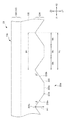
図7は、第2実施形態の背面側単位光学形状233を説明する図である。図7では、前述の図3と同様の断面(XZ面に平行な断面)の一部を拡大して示している。
導光板23は、前述の図6に示すように、入光面23a,23b、出光面13c、背面23dを有している。
入光面23a,23bは、導光板23のX方向の両側面であり、X方向において互いに対向しており、それぞれ、光源部22A,22Bからの光が入射する面である。
出光面13cは、前述の第1実施形態の出光面と同様であり、出光側単位光学形状131がY方向に複数配列されて形成された出光側光学形状部132を有している。
背面23dは、背面側単位光学形状233が複数配列されて形成された背面側光学形状部234を有している。
また、導光板23は、Z方向において(厚み方向において)、出光側光学形状部132と背面側光学形状部234との間には、厚さが一定の本体部135を備え、これらは一体に積層されている。
FIG. 7 is a diagram illustrating the back-side unit
As shown in FIG. 6 described above, the
The light incident surfaces 23a and 23b are both side surfaces in the X direction of the
The
The
The
背面側単位光学形状233は、背面側に凸となる略四角柱形状であり、Y方向を長手方向とし、X方向に互いに隣接して複数配列されている。
背面側単位光学形状233は、XZ面に平行な断面(その配列方向に平行であってシート面に直交する断面)において、背面側に凸となる略台形形状であり、頂面部233cと、頂面部233cを挟んで対向する第1斜面部233a及び第2斜面部233bを有している。理解を容易にするために、X方向において入光面23a側(X1側)に位置する斜面部を第1斜面部233aとし、入光面23b側(X2側)に位置する斜面部を第2斜面部233bとする。
The back-side unit
The back-side unit
本実施形態の頂面部233cは、板面(XY面)に対して略平行となっており、前述のように、角度γ=0°である。
また、本実施形態では、第1斜面部233a及び第2斜面部233bが板面となす角度は、いずれも角度βとなっている。この角度βは、前述のように、1°≦β≦5°を満たしている。
本実施形態では、X方向の両端部に光源部22A,22Bが設けられており、背面側単位光学形状233の配列方向(光の導光方向)において第1斜面部233aは、入光面23bに対向し、第2斜面部233bは、入光面23aに対向する斜面部であり、第1斜面部233a及び第2斜面部233bには、導光板23内を導光する光の少なくとも一部が入射して全反射する。
The
In the present embodiment, the angle formed between the first
In the present embodiment, the
本実施形態の背面側単位光学形状233の配列ピッチP1は、配列方向(X方向)において一定である。この配列ピッチP1は、背面側単位光学形状233の配列方向における幅W1に等しい(P1=W1)形態となっている。
また、背面側単位光学形状133の高さ(頂点133tから谷底となる点133vまでの寸法)は、H1である。
背面側単位光学形状233の配列方向(X方向)において、入光面23aから中央までは、配列方向における頂面部233cの寸法Wcが次第に小さくなり、中央から入光面23bまでは、寸法Wcが次第に大きくなっている。従って、背面側単位光学形状233の配列方向(X方向)において、頂面部233cの寸法Wcと配列ピッチP1との比Wc/P1は、中央が最も小さく、入光面23a,23b側が最も大きくなっている。
以上のことから、本実施形態の導光板23の背面23dの形状は、背面側単位光学形状233の配列方向において、その中央を軸として対称な形状となっている。
本実施形態においても、比Wc/P1は、0.05≦Wc/P1≦0.95を満たすことが好ましい。
The arrangement pitch P1 of the back side unit
Further, the height (the dimension from the
In the arrangement direction (X direction) of the back-side unit
From the above, the shape of the
Also in the present embodiment, the ratio Wc / P1 preferably satisfies 0.05 ≦ Wc / P1 ≦ 0.95.
また、本実施形態においても、背面側単位光学形状133の配列方向(X方向)において、入光面23b,23aに対向する斜面部である第1斜面部233a及び第2斜面部133bの寸法Wd(ただし、本実施形態では、Wd=Wa+Wb)と、配列ピッチP1との比Wd/P1は、0.05≦Wb/P1≦0.95を満たすことが好ましい。
さらに、本実施形態においても、背面側光学形状部134を正面方向(Z方向)から見たとき、入光面23b,23aに対向する斜面部である第1斜面部233a及び第2斜面部233bが占める総面積をM1とし、背面13dの面積をM0とするとき、面積比M1/M0は、0.4≦M1/M0≦0.6を満たすことが好ましい。
Also in the present embodiment, the dimension Wd of the first
Furthermore, also in this embodiment, when the back surface side
本実施形態によれば、2つの光源部22A,22Bを備える面光源装置20及び透過型表示装置2においても、導光板23のモアレ(自己モアレ)の発生を回避することができ、かつ、モアレに起因する輝度ムラが低減され、明るさの面均一性の高い面光源装置20及び透過型表示装置2とすることができる。
According to this embodiment, even in the surface
(実施例と比較例との比較)
ここで、第1実施形態の導光板13に相当する実施例1の導光板と、第2実施形態の導光板23に相当する実施例2の導光板と、これらの比較例に相当する比較例1,2,3の導光板とを用意した。
(Comparison between Examples and Comparative Examples)
Here, the light guide plate of Example 1 corresponding to the
(実施例1の導光板13)
X方向が150mm、Y方向が200mm、総厚が約0.8mm
・背面側単位光学形状133:
配列ピッチP1=0.2mm
配列方向における頂面部133cの寸法Wc=0.05〜0.15mm(入光面13a側端部でWc=0.15mm、対向面13b側端部でWc=0.05mmとなるように連続的に変化)
比Wc/P1は、0.25〜0.75
比Wd/P1は、約0.25〜約0.75
比M1/M0=0.5
角度α=70°、角度β=2°、角度γ=0°
・出光側単位光学形状131
断面形状が略五角形形状である多角柱状。断面形状は、Y方向において対称な形状。
頂角δ=140°
底角=45°
配列ピッチP2=50μm
(
X direction is 150mm, Y direction is 200mm, total thickness is about 0.8mm
-Rear unit optical shape 133:
Arrangement pitch P1 = 0.2mm
The dimension Wc of the
The ratio Wc / P1 is 0.25 to 0.75.
The ratio Wd / P1 is about 0.25 to about 0.75.
Ratio M1 / M0 = 0.5
Angle α = 70 °, angle β = 2 °, angle γ = 0 °
-Output side unit
Polygonal column shape with a substantially pentagonal cross section. The cross-sectional shape is symmetrical in the Y direction.
Vertical angle δ = 140 °
Base angle = 45 °
Arrangement pitch P2 = 50 μm
(実施例2の導光板23)
X方向が200mm、Y方向が150mm、総厚が約0.8mm
・背面側単位光学形状233:
配列ピッチP1=0.2mm
配列方向における頂面部133cの寸法Wc=0.05〜0.15mm(入光面23a,23b側端部でWc=0.15mm、中央でWc=0.05mmとなるように連続的に変化)
比Wc/P1は、0.25〜0.75
比Wd/P1は、0.25〜0.75
比M1/M0=0.5
角度β=4°、角度γ=0°
・出光側単位光学形状131
断面形状が略五角形形状である多角柱状。断面形状は、Y方向において対称な形状。
頂角δ=140°
底角=45°
配列ピッチP2=50μm
(
X direction is 200mm, Y direction is 150mm, total thickness is about 0.8mm
-Rear unit optical shape 233:
Arrangement pitch P1 = 0.2mm
Dimension Wc of
The ratio Wc / P1 is 0.25 to 0.75.
The ratio Wd / P1 is 0.25 to 0.75.
Ratio M1 / M0 = 0.5
Angle β = 4 °, angle γ = 0 °
-Output side unit
Polygonal column shape with a substantially pentagonal cross section. The cross-sectional shape is symmetrical in the Y direction.
Vertical angle δ = 140 °
Base angle = 45 °
Arrangement pitch P2 = 50 μm
(比較例1の導光板)
比較例1の導光板は、実施例1の導光板13の比較例に相当し、背面側単位光学形状133の配列ピッチP1が配列方向において次第に、連続的に変化し、寸法Wcが一定である点以外は、前述の実施例1の導光板と同様である。
・背面側単位光学形状133:
配列ピッチP1は、約0.067〜0.2mm(入光面23a側端部でP1が約0.067mm、対向面13b側端部でP1=0.2mmとなるように連続的に変化)
配列方向における頂面部133cの寸法Wc=0.05mm
比Wc/P1は、0.25〜0.75
比Wd/P1は、約0.25〜約0.75
比M1/M0は、約0.5
角度α=70°、角度β=2°、角度γ=0°
(Light guide plate of Comparative Example 1)
The light guide plate of Comparative Example 1 corresponds to a comparative example of the
-Rear unit optical shape 133:
The arrangement pitch P1 is about 0.067 to 0.2 mm (continuously changing so that P1 is about 0.067 mm at the end on the
Dimension Wc of
The ratio Wc / P1 is 0.25 to 0.75.
The ratio Wd / P1 is about 0.25 to about 0.75.
The ratio M1 / M0 is about 0.5
Angle α = 70 °, angle β = 2 °, angle γ = 0 °
(比較例2の導光板)
比較例2の導光板は、実施例1の導光板13の比較例に相当し、背面側単位光学形状233の配列ピッチP1及び寸法Wcが一定である点以外は、前述の実施例1の導光板と同様である。
・背面側単位光学形状133:
配列ピッチP1=0.2mm
配列方向における頂面部133cの寸法Wc=0.06mm
比Wc/P1は、0.3
比Wd/P1は、約0.7
比M1/M0は、約0.7
角度α=70°、角度β=2°、角度γ=0°
(Light guide plate of Comparative Example 2)
The light guide plate of Comparative Example 2 corresponds to a comparative example of the
-Rear unit optical shape 133:
Arrangement pitch P1 = 0.2mm
Dimension Wc of
The ratio Wc / P1 is 0.3
The ratio Wd / P1 is about 0.7
The ratio M1 / M0 is about 0.7
Angle α = 70 °, angle β = 2 °, angle γ = 0 °
(比較例3の導光板)
比較例3の導光板は、実施例2の導光板23の比較例に相当し、背面側単位光学形状233の配列ピッチP1が配列方向において次第に、連続的に変化し、寸法Wcが一定である点以外は、前述の実施例2の導光板と同様である。
・背面側単位光学形状233:
配列ピッチP1は、約0.067mm〜0.2mm(入光面23a,23b側端部でP1が約0.067mm、X方向の中央でP1=0.2mmとなるように連続的に変化)
配列方向における頂面部233cの寸法Wc=0.05mm
比Wc/P1は、0.25〜0.75
比Wd/P1は、約0.25〜約0.75
比M1/M0は、約0.5
角度β=4°、角度γ=0°
(Light guide plate of Comparative Example 3)
The light guide plate of Comparative Example 3 corresponds to a comparative example of the
-Rear unit optical shape 233:
The arrangement pitch P1 is about 0.067 mm to 0.2 mm (continuously changing so that P1 is about 0.067 mm at the end portions on the light incident surfaces 23a and 23b side, and P1 = 0.2 mm at the center in the X direction).
Dimension Wc of
The ratio Wc / P1 is 0.25 to 0.75.
The ratio Wd / P1 is about 0.25 to about 0.75.
The ratio M1 / M0 is about 0.5
Angle β = 4 °, angle γ = 0 °
これらの実施例1,2及び比較例1〜3の導光板に、各光源部12、22A,22Bから光を投射し、その出射側にプリズムシート14や光拡散シート15を配置した面光源装置10,20の状態でモアレが観察されるか否かを評価した。
比較例1の導光板を備える面光源装置では、出射光量の分布が均一であり、即ち、明るさの面内均一性が良好であり、輝度ムラ等は発生しなかったが、面光源装置の状態であっても、導光板のモアレ(自己モアレ)が視認されていた。
比較例2の導光板を備える面光源装置では、導光板のモアレ(自己モアレ)は観察されなかったが、光源部12から離れるに出射光量が小さくなり、明るさの面内均一性が低下していた。また、光の利用効率も低下していた。
比較例3の導光板を備える面光源装置では、出射光量の分布が均一であり、明るさの面内均一性が良好であり、輝度ムラ等は発生しなかったが、面光源装置の状態であっても、導光板のモアレ(自己モアレ)が観察されていた。このモアレは、配列ピッチP1が大きくなるX方向の中央部分で特に顕著に発生しており、良好な照明の大きな妨げとなっていた。
これに対して、実施例1,2の導光板を備えた面光源装置では、導光板のみを観察した場合にも、面光源装置として観察した場合にも、導光板のモアレ(自己モアレ)が観察されなかった。また、実施例1,2の導光板では、導光効率、光の取り出し効率等も良好であり、明るく、輝度ムラもなく、明るさの面内均一性の高い良好な照明であった。
A surface light source device in which light is projected from each of the
In the surface light source device including the light guide plate of Comparative Example 1, the distribution of the emitted light amount is uniform, that is, the in-plane uniformity of brightness is good, and luminance unevenness does not occur. Even in the state, moire (self moire) of the light guide plate was visually recognized.
In the surface light source device including the light guide plate of Comparative Example 2, no moire (self moire) of the light guide plate was observed, but the amount of emitted light decreased as the distance from the
In the surface light source device including the light guide plate of Comparative Example 3, the distribution of the emitted light amount is uniform, the in-plane uniformity of brightness is good, and brightness unevenness does not occur, but in the state of the surface light source device Even in this case, moire (self moire) of the light guide plate was observed. This moire is particularly noticeable at the central portion in the X direction where the arrangement pitch P1 is large, which is a great hindrance to good illumination.
On the other hand, in the surface light source device including the light guide plate of Examples 1 and 2, the moire (self moire) of the light guide plate is observed both when the light guide plate is observed and when the surface light source device is observed. Not observed. In addition, the light guide plates of Examples 1 and 2 had good light guide efficiency, light extraction efficiency, and the like, were bright, had no brightness unevenness, and had good illumination with high in-plane uniformity of brightness.
(変形形態)
以上説明した各実施形態に限定されることなく、種々の変形や変更が可能であって、それらも本発明の範囲内である。
(Deformation)
Without being limited to the embodiments described above, various modifications and changes are possible, and these are also within the scope of the present invention.
(1)各実施形態において、面光源装置10,20は、導光板13,23よりもLCDパネル11側(Z2側)に、プリズムシート14、光拡散シート15等を備える例を示したが、これに限らず、プリズムシート14の導光板13,23側(Z1側)又はLCDパネル11側(Z2側)に、各種レンズ形状やプリズム形状が形成された他の光学シート等をさらに組み合わせて配置してもよい。また、プリズムシート14に換えて、他の光学シートを用いてもよいし、光拡散シート15を用いなくてもよい。
面光源装置10,20及び透過型表示装置1,2の使用環境や所望する光学性能に合わせて、面光源装置10,20として導光板13,23と組み合わせて用いる各種光学シート等は、適宜選択して用いることができる。
(1) In each embodiment, although the surface
Various optical sheets used in combination with the
(2)各実施形態において、導光板13,23は、その出光面13cに、出光側単位光学形状131として、複数種類のレンズを組み合わせたものを複数配列してもよい。
(2) In each embodiment, the
(3)各実施形態において、反射シート16は、シート状であり、導光板13,23とは別体である例を示したが、これに限らず、例えば、導光板13,23の背面側(Z1側)に、背面側単位光学形状133,233の凹凸に追従して、一体に形成されていてもよい。なお、この場合の反射シートの反射面は、鏡面反射を主とするものが好ましい。
また、反射シートではなく、導光板13,23の背面側(Z1側)に位置する筐体の導光板13側(Z2側)の面に、光反射性を有する塗料や金属箔等を塗付又は転写等して形成してもよい。
(3) In each embodiment, although the
In addition, a light-reflective coating or metal foil is applied to the surface of the housing located on the back side (Z1 side) of the
(4)各実施形態において、本体部135の厚さが一定であり、導光板13の総厚(Z方向における厚さ)が略一定である例を示したが、これに限らず、例えば、第1実施形態では、出光面13cに直交しかつ背面側単位光学形状133の配列方向に平行な断面(XZ面に平行な断面)において、本体部135の厚さが、入光面13a側(X1側)が厚く、対向面13b側(X2側)へ進むにつれて次第に薄くなる形状とし、入光面13a側(X1側)が厚く、対向面13b側へ進むにつれて厚みが次第に薄くなる導光板13としてもよい。
なお、このとき、背面13dは、出光面13cやXY面に平行ではなく、頂面部133cの角度γ等は、背面13dに平行な面に対してなす角度とする。
(4) In each embodiment, an example in which the thickness of the
At this time, the
なお、本実施形態及び変形形態は、適宜組み合わせて用いることもできるが、詳細な説明は省略する。また、本発明は以上説明した各実施形態によって限定されることはない。 In addition, although this embodiment and modification can also be used in combination as appropriate, detailed description is abbreviate | omitted. Further, the present invention is not limited by the embodiments described above.
1,2 表示装置
11 LCDパネル
12,22A,22B 光源部
121 点光源
13,23 導光板
131 出光側単位光学形状
132 出光側光学形状部
133,233 背面側単位光学形状
134 背面側光学形状部
135 本体部
13a,23a,23b 入光面
13b 対向面
13c 出光面
13d,23d 背面
14 プリズムシート
15 光拡散シート
16 反射シート
DESCRIPTION OF SYMBOLS 1, 2
Claims (7)
前記背面には、光の導光方向に略平行な方向を配列方向として背面側単位光学形状が互いに隣接して複数配列され、
前記背面側単位光学形状は、
背面側に凸となる略四角柱形状であり、頂面部と、前記頂面部を挟んで対向する位置に形成される側面である第1斜面部及び第2斜面部を有し、
前記配列方向における前記背面側単位光学形状の配列ピッチをP1とし、配列方向における前記頂面部の寸法をWcとするとき、
前記配列ピッチは一定であり、
前記配列方向において、前記入光面から離れるにつれて、比Wc/P1が小さくなり、
前記頂面部が、前記配列方向において前記背面となす角度をγとし、
前記第1斜面部及び前記第2斜面部のうち、前記配列方向において前記入光面に対向する斜面部が前記配列方向において前記背面となす角度をβとするとき、βは一定であり、
0°≦γ≦0.5°
1°≦β≦5°
という関係を満たすこと、
を特徴とする導光板。 A light guide plate comprising a light incident surface on which light from a light source part is incident, a light output surface from which light is emitted, and a back surface facing the light output surface,
On the back side, a plurality of back side unit optical shapes are arranged adjacent to each other with the direction substantially parallel to the light guiding direction as the arrangement direction,
The back unit optical shape is
It has a substantially quadrangular prism shape that is convex on the back side, and has a top surface portion, a first slope portion and a second slope portion that are side surfaces formed at positions facing each other across the top surface portion,
When the arrangement pitch of the back side unit optical shapes in the arrangement direction is P1, and the dimension of the top surface portion in the arrangement direction is Wc,
The array pitch is constant;
In the arrangement direction, the ratio Wc / P1 decreases as the distance from the light incident surface increases.
The angle between the top surface portion and the back surface in the arrangement direction is γ,
Of the first slope portion and the second slope portion, when β is an angle between the slope portion facing the light incident surface in the arrangement direction and the back surface in the arrangement direction, β is constant,
0 ° ≦ γ ≦ 0.5 °
1 ° ≦ β ≦ 5 °
Satisfying the relationship
A light guide plate characterized by
前記第1斜面部及び前記第2斜面部のうち、前記配列方向において前記入光面に対向する斜面部の前記配列方向の寸法をWdとするとき、比Wd/P1は、
0.05≦Wd/P1≦0.95
という関係を満たすこと、
を特徴とする導光板。 The light guide plate according to claim 1,
Of the first slope portion and the second slope portion, when the dimension in the arrangement direction of the slope portion facing the light incident surface in the arrangement direction is Wd, the ratio Wd / P1 is
0.05 ≦ Wd / P1 ≦ 0.95
Satisfying the relationship
A light guide plate characterized by
前記背面を法線方向から見たときに、前記第1斜面部及び前記第2斜面部のうち、前記配列方向において前記入光面に対向する斜面部が占める総面積をM1とし、前記背面をその法線方向から見たときの面積をM0とするとき、比M1/M0は、
0.4≦M1/M0≦0.6
という関係を満たすこと、
を特徴とする導光板。 In the light guide plate according to claim 1 or 2,
When the back surface is viewed from the normal direction, the total area occupied by the slope portion facing the light incident surface in the arrangement direction of the first slope portion and the second slope portion is M1, and the back surface is When the area when viewed from the normal direction is M0, the ratio M1 / M0 is
0.4 ≦ M1 / M0 ≦ 0.6
Satisfying the relationship
A light guide plate characterized by
前記入光面へ入射する光を発する光源部と、
前記導光板からの光を正面方向又は正面方向となす角度が小さい方向へ向ける偏向光学シートと、
を備える面光源装置。 The light guide plate according to any one of claims 1 to 3,
A light source unit that emits light incident on the light incident surface;
A deflection optical sheet for directing light from the light guide plate in a front direction or in a direction with a small angle with the front direction; and
A surface light source device comprising:
前記光源部は1つであり、
前記背面側単位光学形状内において、前記第1斜面部が前記入光面側に位置し、
前記第1斜面部は、前記背面となす角度が前記導光板と空気との界面における臨界角以上であり、前記光源部から導光する光が入射しないこと、
を特徴とする面光源装置。 The surface light source device according to claim 4,
The light source unit is one,
In the back side unit optical shape, the first slope portion is located on the light incident surface side,
The first inclined surface portion has an angle formed with the back surface that is equal to or greater than a critical angle at an interface between the light guide plate and air, and light guided from the light source portion is not incident;
A surface light source device.
前記光源部は、2つであり、前記導光板の互いに対向する両側面である前記入光面に面する位置に設けられ、
前記第1斜面部が前記背面となす角度と、前記第2斜面部が前記背面となす角度とは、等しいこと、
を特徴とする面光源装置。 The surface light source device according to claim 4,
The light source part is two, and is provided at a position facing the light incident surface which is both opposite side surfaces of the light guide plate,
The angle formed by the first slope portion with the back surface and the angle formed by the second slope portion with the back surface are equal.
A surface light source device.
前記面光源装置に背面側から照明される透過型表示部と、
を備える透過型表示装置。 A surface light source device according to any one of claims 4 to 6,
A transmissive display unit illuminated from the back side to the surface light source device;
A transmissive display device.
Priority Applications (1)
| Application Number | Priority Date | Filing Date | Title |
|---|---|---|---|
| JP2012179601A JP5765301B2 (en) | 2012-08-13 | 2012-08-13 | Light guide plate, surface light source device, transmissive display device |
Applications Claiming Priority (1)
| Application Number | Priority Date | Filing Date | Title |
|---|---|---|---|
| JP2012179601A JP5765301B2 (en) | 2012-08-13 | 2012-08-13 | Light guide plate, surface light source device, transmissive display device |
Publications (3)
| Publication Number | Publication Date |
|---|---|
| JP2014038747A JP2014038747A (en) | 2014-02-27 |
| JP2014038747A5 JP2014038747A5 (en) | 2015-02-12 |
| JP5765301B2 true JP5765301B2 (en) | 2015-08-19 |
Family
ID=50286727
Family Applications (1)
| Application Number | Title | Priority Date | Filing Date |
|---|---|---|---|
| JP2012179601A Active JP5765301B2 (en) | 2012-08-13 | 2012-08-13 | Light guide plate, surface light source device, transmissive display device |
Country Status (1)
| Country | Link |
|---|---|
| JP (1) | JP5765301B2 (en) |
Families Citing this family (9)
| Publication number | Priority date | Publication date | Assignee | Title |
|---|---|---|---|---|
| JP5679020B1 (en) * | 2013-09-03 | 2015-03-04 | 大日本印刷株式会社 | Light guide plate, surface light source device, transmissive display device |
| US9239420B2 (en) | 2013-07-26 | 2016-01-19 | Dai Nippon Printing Co., Ltd. | Light guide plate, surface source device and transmission-type display device |
| JP5700084B2 (en) * | 2013-07-26 | 2015-04-15 | 大日本印刷株式会社 | Light guide plate, surface light source device, transmissive display device |
| JP6354207B2 (en) * | 2014-02-28 | 2018-07-11 | 大日本印刷株式会社 | Reflective sheet, surface light source device, transmissive display device |
| JP6424457B2 (en) * | 2014-04-23 | 2018-11-21 | 凸版印刷株式会社 | Automotive display device |
| JP5700169B2 (en) * | 2014-12-18 | 2015-04-15 | 大日本印刷株式会社 | Light guide plate, surface light source device, transmissive display device |
| JP2016134332A (en) * | 2015-01-21 | 2016-07-25 | 大日本印刷株式会社 | Light guide plate, surface light source device, and transmission type display device |
| JP6500613B2 (en) * | 2015-06-05 | 2019-04-17 | 大日本印刷株式会社 | Light guide plate, surface light source device, transmission type display device |
| CN114815032A (en) * | 2021-01-19 | 2022-07-29 | 光耀科技股份有限公司 | Light guide film and backlight module |
Family Cites Families (4)
| Publication number | Priority date | Publication date | Assignee | Title |
|---|---|---|---|---|
| JP2007225788A (en) * | 2006-02-22 | 2007-09-06 | Citizen Electronics Co Ltd | Light guide plate, front and rear integrally formed backlight using light guide plate and liquid crystal display device using backlight |
| KR20090101156A (en) * | 2006-09-29 | 2009-09-24 | 도레이 카부시키가이샤 | Surface light source and liquid crystal display device using the same |
| US20110299013A1 (en) * | 2009-03-06 | 2011-12-08 | Sharp Kabushiki Kaisha | Planar illumination device and display device provided with the same |
| JP5306029B2 (en) * | 2009-04-10 | 2013-10-02 | 三菱電機株式会社 | Backlight and display device having the same |
-
2012
- 2012-08-13 JP JP2012179601A patent/JP5765301B2/en active Active
Also Published As
| Publication number | Publication date |
|---|---|
| JP2014038747A (en) | 2014-02-27 |
Similar Documents
| Publication | Publication Date | Title |
|---|---|---|
| JP5765301B2 (en) | Light guide plate, surface light source device, transmissive display device | |
| JP5919964B2 (en) | Light guide plate, surface light source device, display device | |
| JP2012164583A (en) | Light guide plate, surface light source device, and transmission type display device | |
| JP5700084B2 (en) | Light guide plate, surface light source device, transmissive display device | |
| JP6354207B2 (en) | Reflective sheet, surface light source device, transmissive display device | |
| JP5804216B2 (en) | Light guide plate, surface light source device, transmissive display device | |
| JP5804011B2 (en) | Transmission type display device | |
| JP5929552B2 (en) | Light guide plate, surface light source device, transmissive display device | |
| JP5664609B2 (en) | Light guide plate, surface light source device, transmissive display device | |
| JP2017208287A (en) | Surface light source device and transmission type display device | |
| JP5700169B2 (en) | Light guide plate, surface light source device, transmissive display device | |
| JP4730339B2 (en) | Surface light source device, transmissive display device | |
| JP6593183B2 (en) | Light guide plate, surface light source device, transmissive display device | |
| JP2017004637A (en) | Light guide plate, surface light source device, transmission type display device | |
| JP2016154119A (en) | Light guide plate, surface light source device and transparent type display device | |
| JP2015069932A (en) | Surface light source device and transmission type display device | |
| JP2016134353A (en) | Light guide plate, surface light source device, and transmission type display device | |
| JP2015176709A (en) | Surface light source device, transmission type display device | |
| JP2015191818A (en) | Surface light source device and transmission type display device | |
| JP5935459B2 (en) | Light guide plate, surface light source device, display device | |
| JP2008305585A (en) | Surface light source and transmission type display device | |
| JP2013068834A (en) | Liquid crystal display device | |
| JP6020687B1 (en) | Light guide plate, surface light source device, transmissive display device | |
| JP2015069764A (en) | Reflection sheet, surface light source device and transparent type display device | |
| JP4730340B2 (en) | Surface light source device, transmissive display device |
Legal Events
| Date | Code | Title | Description |
|---|---|---|---|
| A521 | Written amendment |
Free format text: JAPANESE INTERMEDIATE CODE: A523 Effective date: 20141217 |
|
| A621 | Written request for application examination |
Free format text: JAPANESE INTERMEDIATE CODE: A621 Effective date: 20141217 |
|
| A871 | Explanation of circumstances concerning accelerated examination |
Free format text: JAPANESE INTERMEDIATE CODE: A871 Effective date: 20141217 |
|
| A975 | Report on accelerated examination |
Free format text: JAPANESE INTERMEDIATE CODE: A971005 Effective date: 20150127 |
|
| A131 | Notification of reasons for refusal |
Free format text: JAPANESE INTERMEDIATE CODE: A131 Effective date: 20150203 |
|
| A521 | Written amendment |
Free format text: JAPANESE INTERMEDIATE CODE: A523 Effective date: 20150331 |
|
| TRDD | Decision of grant or rejection written | ||
| A01 | Written decision to grant a patent or to grant a registration (utility model) |
Free format text: JAPANESE INTERMEDIATE CODE: A01 Effective date: 20150519 |
|
| A61 | First payment of annual fees (during grant procedure) |
Free format text: JAPANESE INTERMEDIATE CODE: A61 Effective date: 20150601 |
|
| R150 | Certificate of patent or registration of utility model |
Ref document number: 5765301 Country of ref document: JP Free format text: JAPANESE INTERMEDIATE CODE: R150 |
|
| RD04 | Notification of resignation of power of attorney |
Free format text: JAPANESE INTERMEDIATE CODE: R3D04 |