JP2006336828A - Molding - Google Patents
Molding Download PDFInfo
- Publication number
- JP2006336828A JP2006336828A JP2005165683A JP2005165683A JP2006336828A JP 2006336828 A JP2006336828 A JP 2006336828A JP 2005165683 A JP2005165683 A JP 2005165683A JP 2005165683 A JP2005165683 A JP 2005165683A JP 2006336828 A JP2006336828 A JP 2006336828A
- Authority
- JP
- Japan
- Prior art keywords
- gel
- synthetic resin
- mounting surface
- resin sheet
- opening
- Prior art date
- Legal status (The legal status is an assumption and is not a legal conclusion. Google has not performed a legal analysis and makes no representation as to the accuracy of the status listed.)
- Granted
Links
Images


Landscapes
- Clamps And Clips (AREA)
- Hooks, Suction Cups, And Attachment By Adhesive Means (AREA)
- Adhesive Tapes (AREA)
- Adhesives Or Adhesive Processes (AREA)
Abstract
Description
本発明は、合成樹脂又は金属成形品の技術分野に属する。 The present invention belongs to the technical field of synthetic resins or metal molded products.
例えば壁面、板金、電子機器の筐体などに取り付けて使用される合成樹脂又は金属の成形品がある。一例をあげると、実開昭57−104081号公報(特許文献1)に記載されたクランプがある。その他にも、電子機器の筐体とプリント基板とに介装されるスペーサ等がある。 For example, there are synthetic resin or metal molded products that are used by attaching to a wall surface, a sheet metal, a casing of an electronic device, or the like. As an example, there is a clamp described in Japanese Utility Model Laid-Open No. 57-104081 (Patent Document 1). In addition, there are spacers interposed between the casing of the electronic device and the printed circuit board.
これらは、それぞれがクランプ、スペーサなどとしての機能を果たすための機能部は互いに異なるものの、壁面等の他の物体に取り付けるための取付基部を備える点で共通している。
従来例として示した成形品を例えば壁面に取り付けるには、ねじ止め等の固定方法もあるが、両面粘着テープを用いることが多かった。
しかしながら、両面粘着テープの場合、貼り直しが困難であり、また剥がしたときに痕が残るという欠点がある。
In order to attach a molded product shown as a conventional example to a wall surface, for example, there is a fixing method such as screwing, but a double-sided adhesive tape is often used.
However, double-sided pressure-sensitive adhesive tapes have drawbacks that it is difficult to reapply and that marks remain when peeled off.
請求項1記載の成形品は、
他の物体に取り付けるための取付面を有する取付基部と、前記取付基部に連接された機能部とを備える合成樹脂又は金属成形品であり、
前記取付面に粘着性のゲルが付着され、
該ゲルの前記取付面とは反対側の表面は薄材に被覆され、
該薄材には前記ゲルを露呈させる開口部が設けられている
ことを特徴とする。
The molded product according to
A synthetic resin or metal molded article comprising an attachment base having an attachment surface for attachment to another object, and a functional part connected to the attachment base;
An adhesive gel is attached to the mounting surface,
The surface of the gel opposite to the mounting surface is coated with a thin material,
The thin material is provided with an opening for exposing the gel.
請求項1の成形品は取付基部を備えており、取付基部には取付面が設けられている。取付面は、曲面でもよいが、平坦面である方が汎用性に優れている。
この取付面には粘着性のゲルが付着される。
The molded product of
An adhesive gel is attached to the mounting surface.
ゲルは、多数の高分子が鎖の上の特定部分の結合により互いに部分的につながってできた三次元網目状構造を持つ高分子材料であるが、本発明には、三次元網目状構造を持つベースポリマーの網目組織の間隙に軟化剤(例えばオイル成分)を包含して流動性を失った状態にしたものが好適である。 A gel is a polymer material having a three-dimensional network structure in which a large number of polymers are partially connected to each other by bonding of specific parts on the chain. It is preferable that a softening agent (for example, an oil component) is included in the gap between the network structures of the base polymer to have lost fluidity.
そのベースポリマーとしては、例えば、スチレン系、オレフィン系、エステル系、アミド系、ウレタン系などの各種熱可塑性エラストマー、並びに、これらの水添、その他による変成物、あるいは、スチレン系、ABS系、オレフィン系、塩化ビニル系、アクリル系、カーボネート系、アセタール系、ナイロン系、ハロゲン化オレフィン系(四フッ化エチレン系、フッ化−塩化エチレン系、フッ化エチレンプロピレン系など)、セルロース系(エチルセルロース系など)の熱可塑性樹脂、及びこれらの樹脂のゴム変成物などが挙げられる。なお、これらの各種熱可塑性樹脂は、単独で用いても、2種以上をブレンドして用いてもよい。 Examples of the base polymer include various thermoplastic elastomers such as styrene, olefin, ester, amide, and urethane, and hydrogenated or other modified products thereof, or styrene, ABS, and olefin. Type, vinyl chloride type, acrylic type, carbonate type, acetal type, nylon type, halogenated olefin type (tetrafluoroethylene type, fluorinated ethylene chloride type, fluorinated ethylene propylene type, etc.), cellulose type (ethylcellulose type, etc.) ), And rubber modified products of these resins. In addition, these various thermoplastic resins may be used independently, or 2 or more types may be blended and used.
軟化剤としては、鉱物油系、植物油系、合成系などの各種ゴム用または樹脂用軟化剤が挙げられる。鉱物油系としては、パラフィン系、ナフテン系、アロマ系などのプロセスオイルが挙げられ、植物油系としては、ひまし油、綿実油、亜麻仁油、菜種油、大豆油、パーム油、椰子油、落花生油、木蝋、パインオイル、オリーブ油などが挙げられる。これらの軟化剤は単独で用いても良いが、互いの相溶性が良好な2種以上を混合させて用いてもよい。なお、軟化剤の添加量が多いほどゲルの硬度は低いものとなるので、所望の硬度となるように調製すればよい。 Examples of the softener include various rubber or resin softeners such as mineral oil, vegetable oil, and synthetic. Examples of mineral oils include paraffinic, naphthenic, and aromatic process oils, and vegetable oils include castor oil, cottonseed oil, linseed oil, rapeseed oil, soybean oil, palm oil, coconut oil, peanut oil, wood wax, Examples include pine oil and olive oil. These softeners may be used alone or in combination of two or more having good compatibility with each other. In addition, since the hardness of a gel becomes so low that there is much addition amount of a softening agent, what is necessary is just to prepare so that it may become desired hardness.
また、クマロン樹脂、クマロン−インデン樹脂、フェノール樹脂、テルペン樹脂、石油樹脂、ロジン樹脂等の各種粘着付与剤(タッキファイヤー)を併用することにより、粘着性を付与又は調整できる。 Moreover, tackiness can be imparted or adjusted by using various tackifiers (tackifier) such as coumarone resin, coumarone-indene resin, phenol resin, terpene resin, petroleum resin, rosin resin and the like.
さらに、ベースポリマー、軟化剤、種粘着付与剤のほか、諸特性の改良のため、公知の樹脂成分などの添加剤を併用することができる。樹脂成分としては、例えば、ポリオレフィン樹脂やポリスチレン樹脂などを併用することができる。これらを添加することにより加工性、耐熱性の向上を図ることができる。ポリオレフィン樹脂としては、例えば、ポリエチレン、アイソタクティックポリプロピレン、プロピレンと他の少量のα−オレフィンとの共重合体(例えば、プロピレン−エチレン共重合体、プロピレン/4−メチル−1−ペンテン共重合体)、ポリ(4−メチル−1−ペンテン)、ポリブテン−1等を挙げることができる。 Furthermore, in addition to the base polymer, softener, and seed tackifier, additives such as known resin components can be used in combination for improving various properties. As the resin component, for example, a polyolefin resin or a polystyrene resin can be used in combination. By adding these, workability and heat resistance can be improved. Examples of the polyolefin resin include polyethylene, isotactic polypropylene, and a copolymer of propylene and a small amount of other α-olefin (for example, propylene-ethylene copolymer, propylene / 4-methyl-1-pentene copolymer). ), Poly (4-methyl-1-pentene), polybutene-1, and the like.
その他の添加剤として、必要に応じて、抗菌剤、ヒンダードアミン系光安定剤、紫外線吸収剤、酸化防止剤、無機充填剤、着色剤を添加できる。
取付面にゲルを付着させる手法に限定はないが、アウトサートが簡便である。
As other additives, antibacterial agents, hindered amine light stabilizers, ultraviolet absorbers, antioxidants, inorganic fillers, and colorants can be added as necessary.
There is no limitation on the method of attaching the gel to the mounting surface, but outsert is simple.
ゲルは取付面の全面に付着させてもよいし、一部に又は一部を除いて付着させてもよい。 ゲルの付着厚みにも特段の制限はないが、薄すぎると、粘着させる相手方の表面凹凸をゲルの変形で補うのが難しくなり、あまり厚くしても使用量が過剰になるだけであるから、自ずと好適な範囲がある。 The gel may be attached to the entire surface of the mounting surface, or may be attached to a part or a part thereof. There is no particular limitation on the adhesion thickness of the gel, but if it is too thin, it will be difficult to compensate for surface irregularities of the other side to be adhered by deformation of the gel, and even if it is too thick, only the amount used will be excessive, There is naturally a suitable range.
ゲルは粘着性があるので、これを露出させたままであると、保管時等にむやみに粘着したり、ほこりなどが付着したりする。しかし、ゲルの取付面とは反対側の表面は薄材に被覆されているので、このような不具合は防止される。 Since the gel is sticky, if it is left exposed, it will stick unnecessarily at the time of storage, etc. or dust will adhere. However, since the surface opposite to the gel mounting surface is covered with a thin material, such a problem is prevented.
なお、薄材の材質に特段の限定はなく、例えばプラスチックフィルム、プラスチックシート、剥離紙等を使用できる。
その薄材にはゲルを露呈させる開口部が設けられている。開口部は、穴又は切欠として設けられるが、その形状に限定はない。但し、開口面積が大きくなると、むやみに粘着したり、ほこりなどが付着したりするおそれがあるので、そうした不都合が生じない寸法にするのが望ましい。開口部の数も制限はないが、仕様によって多くなれば、合計の開口面積が増えることになるから、仮止め力の向上が可能になる。
The material of the thin material is not particularly limited, and for example, a plastic film, a plastic sheet, a release paper, or the like can be used.
The thin material is provided with an opening for exposing the gel. The opening is provided as a hole or notch, but the shape is not limited. However, when the opening area becomes large, there is a risk of sticking unnecessarily, or dust or the like may adhere to it. The number of openings is not limited, but if the number increases depending on the specification, the total opening area increases, so that the temporary fixing force can be improved.
薄材にはゲルを露呈させる開口部が設けられているので、薄材をつけたまま、取付面を取り付け相手方に押しつけるように力をかけると、取付面と相手方との間に生じる圧力でゲルが開口部から押し出されて相手方に粘着する。そして、この力を解除してもゲルは相手方に粘着したままになっているので、成形品が相手方に仮止めされる。この仮止めは、容易に解除することができるし、相手方に引き剥がした痕が残ることはない。また、繰り返し仮止めすることもできる。 Since the thin material is provided with an opening that exposes the gel, if a force is applied to the mounting surface against the mounting partner while the thin material is applied, the gel is generated by the pressure generated between the mounting surface and the counterpart. Is pushed out of the opening and sticks to the other party. And even if this force is released, the gel remains adhered to the other party, so that the molded product is temporarily fixed to the other party. This temporary fixing can be easily released, and there is no trace left on the other party. Moreover, it can also be temporarily fixed temporarily.
仮止めにより成形品の取付位置を決めてから、或いは仮止めを省略して、請求項5記載のように、薄材を剥離させてゲルの表面を露出させ、そのゲルを相手方に粘着させれば成形品を取り付けできる。このときに、取付面を取り付け相手方に押しつけるように力をかければ、ゲルによる粘着がより確実になる。 After determining the mounting position of the molded product by temporary fixing, or omitting temporary fixing, the thin material is peeled off to expose the surface of the gel, and the gel can be adhered to the other party. The molded product can be attached. At this time, if a force is applied so as to press the mounting surface against the mounting counterpart, adhesion by the gel becomes more reliable.
このように取り付けた後でも、成形品を引き剥がすことが可能であるから、貼り直しもできる。しかも、剥がした痕が残らない。
機能部は、成形品の用途等に応じて様々であるが、いくつか例を挙げると、長尺物を把持する把持機能部(特許第1615563号、特開平11−351451号、意匠登録第978223号)、シャーシと間隔を隔ててプリント基板等の板材を支える支持機能部(意匠登録第701407号)、端縁部を保護する保護機能部(意匠登録第978223号)等がある。
Even after mounting in this manner, the molded product can be peeled off, so that it can be re-applied. Moreover, there are no traces removed.
The functional unit varies depending on the application of the molded product. To name a few, a functional unit for gripping a long object (Japanese Patent No. 1615563, Japanese Patent Laid-Open No. 11-351451, Design Registration No. 978223) No.), a support function part (design registration No. 701407) for supporting a plate material such as a printed circuit board at a distance from the chassis, a protection function part (design registration No. 978223) for protecting the edge portion, and the like.
開口部は、請求項2記載のように孔又は切欠にするとよい。その形状については、孔にする場合は円形状、矩形状、三角形状、多角形状、星形状、楕円形状が例示され、切欠きの場合はこれら各形状の半分を切り取った形状が例示される。
The opening may be a hole or a notch as described in
ゲルと取付面との寸法関係は、請求項3記載のように、前記ゲルの前記取付面への投影寸法は前記取付面と等しいか前記取付面よりも小さい構成、すなわちゲルが取付面の側方にはみ出さない構成にするとよい。 The dimensional relationship between the gel and the mounting surface is such that the projected size of the gel onto the mounting surface is equal to or smaller than the mounting surface, that is, the gel is on the side of the mounting surface. It is better to have a configuration that does not protrude.
ゲルの取付面への投影寸法を取付面と等しくすれば、ゲルの側面を用いて上述の仮止めを行える。
ゲルの取付面への投影寸法を取付面より小さくすれば、保管時や作業時においてゲルの側面が他の物体に粘着するのを防止できる。
If the projected dimension of the gel onto the mounting surface is made equal to the mounting surface, the above-described temporary fixing can be performed using the side surface of the gel.
If the projected dimension of the gel on the mounting surface is made smaller than that of the mounting surface, the side surface of the gel can be prevented from sticking to other objects during storage or operation.
ゲルと薄材とのとの寸法関係は、請求項4記載のように、前記ゲルの前記薄材への投影寸法は前記薄材よりも小さい構成、すなわちゲルが薄材からはみ出さない構成にすると保管時や作業時においてゲルの側面が他の物体に粘着するのを防止できる。 The dimensional relationship between the gel and the thin material is such that the projected dimension of the gel onto the thin material is smaller than that of the thin material, that is, the gel does not protrude from the thin material. Then, it is possible to prevent the side surface of the gel from sticking to other objects during storage or operation.
次に、本発明の実施例等により発明の実施の形態を説明する。なお、本発明は下記の実施例等に限定されるものではなく、本発明の要旨を逸脱しない範囲でさまざまに実施できることは言うまでもない。
[実施例]
この実施例は、本発明の成形品をクランプとして具体化した例である。
Next, embodiments of the present invention will be described based on examples of the present invention. The present invention is not limited to the following examples and the like, and it goes without saying that the present invention can be implemented in various ways without departing from the gist of the present invention.
[Example]
In this embodiment, the molded product of the present invention is embodied as a clamp.
図1に示すように、クランプ1は板状の取付基部2、これに連接された帯部3、帯部3の先端に連接された係止弾性部4、取付基部2に連接された係止部5などを備える本体6と、取付基部2の取付面21に付着されたゲル7と、ゲルの取付面21とは反対側の表面71を被覆する合成樹脂シート8(薄材に該当)とで構成される。
As shown in FIG. 1, the
本体6は、合成樹脂(本実施例ではポリプロピレン樹脂であるが、ナイロン、ポリエチレン、POM、ポリカーボネート、アクリル、PBT、PETなどの合成樹脂、TPE(オレフィン系、スチレン系、ポリアミド系、ポリエステル系、ニトリル系、塩素化ポリエチレン、SEBS系等)などエラストマも使用できる。)の射出成形品である。 The main body 6 is a synthetic resin (polypropylene resin in this embodiment, but synthetic resin such as nylon, polyethylene, POM, polycarbonate, acrylic, PBT, PET, etc., TPE (olefin, styrene, polyamide, polyester, nitrile). Elastomers such as chlorinated polyethylene, SEBS, etc.) can also be used.
帯部3は、全体としてC字状に成形されている。4箇所の節部分31では、他の部分よりも肉厚が薄くされていて、節部分31で屈伸しやすくなっている。
係止弾性部4は、略U字状で、そのU字の一端が帯部3の先端に連接されている。
他方の端部からはつまみ片41が外向きに延出されており、そのつまみ片41とU字の底との間には、可動側係止突起42が設けられている。また、帯部3からはつまみ片41と平行状に補助片32が延出されている。
The belt part 3 is formed in a C shape as a whole. The four
The locking
A
係止部5は内側に収容孔51が設けられた箱状で、その内周には固定側係止突起52が設けられている。
係止部5は係止弾性部4を係止させるために設けられている。係止弾性部4を収容孔51に差し込むと、可動側係止突起42が固定側係止突起52に接触することで係止弾性部4が弾性変形し、可動側係止突起42が固定側係止突起52を通過すると、弾性反発して可動側係止突起42を固定側係止突起52に係止させる。
The locking
The locking
このように、係止部5に係止弾性部4を係止させると、帯部3、係止部5及び取付基部2により環状体が形成される。この環状体にて、例えば管やケーブル等の長尺物を把持することができる。
As described above, when the locking
ゲル7は板状であるが、図2(b)に拡大して示すように、その中央部に円形の凹部72が形成されている。
合成樹脂シート8には凹部72よりも直径が大きい開口部81が設けられており、凹部72及びその周辺が開口部81に露呈している。
The
The
ゲル7を取付面21に付着させる手順は、次の通りである。
まず、図3に示すように、クランプ1の本体6を金型の一方(例えば可動側)に保持させて、取付基部2の取付面21と金型の内周面73とで区画されるキャビティCを形成し、さらにキャビティCに開口部81を連通させるように、金型の合わせ面74に合成樹脂シート8を被せる。
The procedure for attaching the
First, as shown in FIG. 3, the cavity 6 is defined by the mounting
そして、閉型することで金型の他方(例えば固定側)を合成樹脂シート8に密接させて、可動側と固定側とで合成樹脂シート8を挟持する。これにより、キャビティCが密閉状になるので、開口部81を通してキャビティCに進入させたノズルからゲル7を吐出させてキャビティCにゲル7を充填する。キャビティCに充填されたゲル7は、その粘着力によって取付面21に付着する。なお、ノズルから吐出されるゲル7は、流動性を良くするために適宜の温度に加熱されている。ゲル7が冷却する時間を待ってから、開型してクランプ1を取り出す。
Then, by closing the mold, the other side (for example, the fixed side) of the mold is brought into close contact with the
このクランプ1は、取付面21に粘着性のゲル7が付着され、ゲル7の表面71は合成樹脂シート8に被覆され、その合成樹脂シート8にはゲル7を露呈させる開口部81が設けられている。
In the
ゲル7は粘着性があるから、これを露出させたままであると、保管時等にむやみに粘着したり、ほこりなどが付着したりする。しかし、ゲル7の表面を合成樹脂シート8にて被覆してあるので、このような不具合は防止される。
Since the
しかも、合成樹脂シート8にはゲル7を露呈させる開口部81が設けられているので、合成樹脂シート8をつけたまま、取付面21を取り付け相手方(例えば板金や筐体)に押しつけるように力をかけると、取付面21と相手方との間に生じる圧力でゲル7が開口部81から押し出されて相手方に粘着する。そして、この力を解除してもゲル7は相手方に粘着したままになっているので、クランプ1が相手方に仮止めされる。この仮止めは、容易に解除することができるし、相手方に引き剥がした痕が残ることはない。また、繰り返し仮止めすることもできる。
Moreover, since the
仮止めによりクランプ1の取付位置を決めてから、或いは仮止めを省略して、合成樹脂シート8を剥離させてゲル7の表面71を露出させ、そのゲル7を相手方に粘着させればクランプ1を取り付けできる。このときに、取付面21を取り付け相手方に押しつけるように力をかければ、ゲル7による粘着がより確実になる。
After determining the mounting position of the
このように取り付けた後でも、クランプ1を引き剥がすことが可能であるから、貼り直しもできる。しかも、剥がした痕が残らない。
なお、本実施例では、長尺物を把持する把持機能部を備えるクランプを例示したが、機能部は、例えば長尺物を把持する把持機能部(特許第1615563号、特開平11−351451号、意匠登録第978223号)、シャーシと間隔を隔ててプリント基板等の板材を支える支持機能部(意匠登録第701407号)、端縁部を保護する保護機能部(意匠登録第978223号)等にできるが、特段の限定はない。
Even after mounting in this manner, the
In the present embodiment, a clamp having a gripping function unit for gripping a long object is illustrated. However, the function part is, for example, a gripping function part for gripping a long object (Japanese Patent No. 1615563, Japanese Patent Laid-Open No. 11-351451). Design registration No. 978223), support function part (design registration No. 701407) for supporting a plate material such as a printed circuit board with a distance from the chassis, protection function part (design registration No. 978223) for protecting the edge portion, etc. Yes, but there are no particular limitations.
また、本実施例では合成樹脂の成形品を例示しているが、例えば実公昭59−8049号公報に記載の配管用止具のような金属製の成形品、意匠登録第387105号公報に記載の電線支持具、意匠登録第638279号公報に記載の電線止具等のような成形品にも本発明を適用できる。
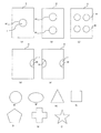
[開口部の各種例]
開口部の位置は、例えば薄材の中心に設けたり、中心以外に設けたりできる。複数の開口部を設けることもできるが、全体的なバランスがよくなるように配置するのが望ましい。 また、3つ以上の開口部を設ける場合には、互いに等間隔に配置すればバランスがよい。
Further, in this embodiment, a synthetic resin molded product is illustrated, but for example, a metal molded product such as a piping stopper described in Japanese Utility Model Publication No. 59-8049, described in Design Registration No. 387105. The present invention is also applicable to molded products such as electric wire supports, electric wire fasteners described in Design Registration No. 638279, and the like.
[Various examples of openings]
The position of the opening can be provided, for example, at the center of the thin material or other than the center. Although a plurality of openings can be provided, it is desirable to arrange them so as to improve the overall balance. When three or more openings are provided, the balance is good if they are arranged at equal intervals.
開口部を切欠にする場合、開口部が薄材の少なくとも1つの端縁部に設けられる構成が好ましい。その場合、切欠である開口部が薄材の相対向する端縁部のほぼ中央に設けられる構成にするとバランスがよい。 When making an opening into a notch, the structure by which an opening is provided in the at least 1 edge part of a thin material is preferable. In that case, the balance is good when the opening portion which is a notch is provided at substantially the center of the opposite edge portions of the thin material.
そうした開口部の形状や配置の例を図4に示す。
図4(a)のように、円形の開口部81を合成樹脂シート8の中央部に設けたり、図4(b)、(c)のように開口部81を点対称又は線対称になる位置に設けたり、また図4(c)のように3つ以上の開口部81を等間隔で配置することもできる。
An example of the shape and arrangement of such openings is shown in FIG.
As shown in FIG. 4A, a
開口部81を切欠にする場合、図4(d)、(e)のように、合成樹脂シート8の少なくとも1つの端縁部に設ければよく、図4(e)のように、合成樹脂シート8の相対向する端縁部のほぼ中央に設けることもできる。
When the
孔である開口部81の形状としては、図4(f)の円形、(g)楕円形、(h)の矩形、(i)の三角形、(j)の多角形、(k)の十字形、(l)星形等にできる。
開口部81を切欠にする場合は、図4(f)〜(l)に示した各形状の半分を切り取った形状にすればよい。
As the shape of the
In the case of making the
1・・・クランプ、
2・・・取付基部、
3・・・帯部、
4・・・係止弾性部、
5・・・係止部、
6・・・本体、
7・・・ゲル、
8・・・合成樹脂シート、
21・・・取付面、
42・・・可動側係止突起、
52・・・固定側係止突起、
71・・・表面、
72・・・凹部、
73・・・内周面、
74・・・合わせ面、
81・・・開口部、
C・・・キャビティ。
1 ... Clamp,
2 ... Mounting base,
3 ... belt part,
4 ... locking elastic part,
5 ... locking part,
6 ... body,
7 ... Gel,
8 ... Synthetic resin sheet,
21 ... Mounting surface,
42 ... movable side locking projection,
52... Fixed side locking projection,
71 ... surface,
72 .. recessed portion,
73 ... inner peripheral surface,
74 ... mating surface,
81 ... opening,
C: Cavity.
Claims (5)
前記取付面に粘着性のゲルが付着され、
該ゲルの前記取付面とは反対側の表面は薄材に被覆され、
該薄材には前記ゲルを露呈させる開口部が少なくとも1箇所設けられている
ことを特徴とする成形品。 A synthetic resin or metal molded article comprising an attachment base having an attachment surface for attachment to another object, and a functional part connected to the attachment base;
An adhesive gel is attached to the mounting surface,
The surface of the gel opposite to the mounting surface is coated with a thin material,
The molded article, wherein the thin material is provided with at least one opening for exposing the gel.
該成形品は、前記薄材を剥離させて露出した前記ゲルにより前記他の物体に粘着させられる
ことを特徴とする成形品。 In the molded product according to any one of claims 1 to 4,
The molded article is adhered to the other object by the gel exposed by peeling the thin material.
Priority Applications (1)
| Application Number | Priority Date | Filing Date | Title |
|---|---|---|---|
| JP2005165683A JP4663410B2 (en) | 2005-06-06 | 2005-06-06 | Molding |
Applications Claiming Priority (1)
| Application Number | Priority Date | Filing Date | Title |
|---|---|---|---|
| JP2005165683A JP4663410B2 (en) | 2005-06-06 | 2005-06-06 | Molding |
Publications (2)
| Publication Number | Publication Date |
|---|---|
| JP2006336828A true JP2006336828A (en) | 2006-12-14 |
| JP4663410B2 JP4663410B2 (en) | 2011-04-06 |
Family
ID=37557551
Family Applications (1)
| Application Number | Title | Priority Date | Filing Date |
|---|---|---|---|
| JP2005165683A Expired - Fee Related JP4663410B2 (en) | 2005-06-06 | 2005-06-06 | Molding |
Country Status (1)
| Country | Link |
|---|---|
| JP (1) | JP4663410B2 (en) |
Cited By (1)
| Publication number | Priority date | Publication date | Assignee | Title |
|---|---|---|---|---|
| JP2011202763A (en) * | 2010-03-26 | 2011-10-13 | Nifco Inc | Fixture |
Citations (9)
| Publication number | Priority date | Publication date | Assignee | Title |
|---|---|---|---|---|
| JPS57167952U (en) * | 1981-04-16 | 1982-10-22 | ||
| JPS6084486A (en) * | 1983-10-14 | 1985-05-13 | 北川工業株式会社 | Electric wire bundle clamp |
| JPS6158327U (en) * | 1984-09-21 | 1986-04-19 | ||
| JPH074422A (en) * | 1993-06-15 | 1995-01-10 | Dia Corp:Kk | Fixture |
| JPH10298516A (en) * | 1997-04-28 | 1998-11-10 | Aisero Kagaku Kk | Adhesive seal |
| JP2001271823A (en) * | 2000-03-24 | 2001-10-05 | Michimasa Hatana | Structure of fixture |
| JP2002322441A (en) * | 2001-04-24 | 2002-11-08 | Kazuma Kobayashi | Masking sheet for coating |
| JP2003028131A (en) * | 2001-07-17 | 2003-01-29 | Michimasa Hatana | Fixing structure by clayey composition |
| JP2003286460A (en) * | 2002-03-28 | 2003-10-10 | Sekisui Chem Co Ltd | Double-adhesive tape |
-
2005
- 2005-06-06 JP JP2005165683A patent/JP4663410B2/en not_active Expired - Fee Related
Patent Citations (9)
| Publication number | Priority date | Publication date | Assignee | Title |
|---|---|---|---|---|
| JPS57167952U (en) * | 1981-04-16 | 1982-10-22 | ||
| JPS6084486A (en) * | 1983-10-14 | 1985-05-13 | 北川工業株式会社 | Electric wire bundle clamp |
| JPS6158327U (en) * | 1984-09-21 | 1986-04-19 | ||
| JPH074422A (en) * | 1993-06-15 | 1995-01-10 | Dia Corp:Kk | Fixture |
| JPH10298516A (en) * | 1997-04-28 | 1998-11-10 | Aisero Kagaku Kk | Adhesive seal |
| JP2001271823A (en) * | 2000-03-24 | 2001-10-05 | Michimasa Hatana | Structure of fixture |
| JP2002322441A (en) * | 2001-04-24 | 2002-11-08 | Kazuma Kobayashi | Masking sheet for coating |
| JP2003028131A (en) * | 2001-07-17 | 2003-01-29 | Michimasa Hatana | Fixing structure by clayey composition |
| JP2003286460A (en) * | 2002-03-28 | 2003-10-10 | Sekisui Chem Co Ltd | Double-adhesive tape |
Cited By (1)
| Publication number | Priority date | Publication date | Assignee | Title |
|---|---|---|---|---|
| JP2011202763A (en) * | 2010-03-26 | 2011-10-13 | Nifco Inc | Fixture |
Also Published As
| Publication number | Publication date |
|---|---|
| JP4663410B2 (en) | 2011-04-06 |
Similar Documents
| Publication | Publication Date | Title |
|---|---|---|
| US9554674B2 (en) | Shower rod mounting assembly | |
| JP2006512440A5 (en) | ||
| CA2285915A1 (en) | Transfer/transfuse member release agent and methods thereof | |
| WO2008102670A1 (en) | Surface protection sheet | |
| JPH11509163A (en) | Component carrier tape | |
| US20100139133A1 (en) | Elastic tags | |
| EP2011845A3 (en) | Adhesive tape and use of the adhesive tape as bandaging tape for cables | |
| EP2017055A4 (en) | Method for production of polymer thin film, and polymer thin film | |
| EP0985525A4 (en) | Molded article and surface covering sheet therefor | |
| US11452249B2 (en) | Carrier for reversibly immobilizing one or more objects | |
| JP4663410B2 (en) | Molding | |
| TW200515499A (en) | Dicing adhesive sheet, dicing method, and manufacturing method of semiconductor device | |
| US20120308784A1 (en) | Adhesive pad | |
| US20200071043A1 (en) | Systems and methods for an object with a bonded adhesive strip | |
| CN110534647B (en) | Flexible substrate, display substrate and display panel | |
| JP2008059086A (en) | Rfid tag structure | |
| JP2017201864A (en) | Electrical component with harness fixing piece | |
| CA2704243C (en) | Elastic tags | |
| HK1067026A1 (en) | Dust removing cleaner | |
| JP2007099858A (en) | Tape for semiconductor processing | |
| JP2009227814A (en) | Releasable adhesive tape and method for releasing the adhesive tape | |
| EP2072214A3 (en) | Multi-layered molded article with EMI protection | |
| JP2015042473A (en) | Storage holder for clear file | |
| JP6822626B1 (en) | Cover tape and packaging for electronic component packaging | |
| JPH09179496A (en) | Tack label and labeled container |
Legal Events
| Date | Code | Title | Description |
|---|---|---|---|
| A621 | Written request for application examination |
Free format text: JAPANESE INTERMEDIATE CODE: A621 Effective date: 20071220 |
|
| A977 | Report on retrieval |
Free format text: JAPANESE INTERMEDIATE CODE: A971007 Effective date: 20100311 |
|
| A131 | Notification of reasons for refusal |
Free format text: JAPANESE INTERMEDIATE CODE: A131 Effective date: 20100316 |
|
| A521 | Written amendment |
Free format text: JAPANESE INTERMEDIATE CODE: A523 Effective date: 20100517 |
|
| TRDD | Decision of grant or rejection written | ||
| A01 | Written decision to grant a patent or to grant a registration (utility model) |
Free format text: JAPANESE INTERMEDIATE CODE: A01 Effective date: 20101207 |
|
| A01 | Written decision to grant a patent or to grant a registration (utility model) |
Free format text: JAPANESE INTERMEDIATE CODE: A01 |
|
| A61 | First payment of annual fees (during grant procedure) |
Free format text: JAPANESE INTERMEDIATE CODE: A61 Effective date: 20110105 |
|
| R150 | Certificate of patent or registration of utility model |
Ref document number: 4663410 Country of ref document: JP Free format text: JAPANESE INTERMEDIATE CODE: R150 Free format text: JAPANESE INTERMEDIATE CODE: R150 |
|
| FPAY | Renewal fee payment (event date is renewal date of database) |
Free format text: PAYMENT UNTIL: 20140114 Year of fee payment: 3 |
|
| FPAY | Renewal fee payment (event date is renewal date of database) |
Free format text: PAYMENT UNTIL: 20140114 Year of fee payment: 3 |
|
| S531 | Written request for registration of change of domicile |
Free format text: JAPANESE INTERMEDIATE CODE: R313531 |
|
| R350 | Written notification of registration of transfer |
Free format text: JAPANESE INTERMEDIATE CODE: R350 |
|
| R250 | Receipt of annual fees |
Free format text: JAPANESE INTERMEDIATE CODE: R250 |
|
| R250 | Receipt of annual fees |
Free format text: JAPANESE INTERMEDIATE CODE: R250 |
|
| R250 | Receipt of annual fees |
Free format text: JAPANESE INTERMEDIATE CODE: R250 |
|
| R250 | Receipt of annual fees |
Free format text: JAPANESE INTERMEDIATE CODE: R250 |
|
| R250 | Receipt of annual fees |
Free format text: JAPANESE INTERMEDIATE CODE: R250 |
|
| R250 | Receipt of annual fees |
Free format text: JAPANESE INTERMEDIATE CODE: R250 |
|
| R250 | Receipt of annual fees |
Free format text: JAPANESE INTERMEDIATE CODE: R250 |
|
| LAPS | Cancellation because of no payment of annual fees |