JP2006334568A - Backwashing system - Google Patents
Backwashing system Download PDFInfo
- Publication number
- JP2006334568A JP2006334568A JP2005166009A JP2005166009A JP2006334568A JP 2006334568 A JP2006334568 A JP 2006334568A JP 2005166009 A JP2005166009 A JP 2005166009A JP 2005166009 A JP2005166009 A JP 2005166009A JP 2006334568 A JP2006334568 A JP 2006334568A
- Authority
- JP
- Japan
- Prior art keywords
- seawater
- backwashing
- wastewater
- storage tank
- tank
- Prior art date
- Legal status (The legal status is an assumption and is not a legal conclusion. Google has not performed a legal analysis and makes no representation as to the accuracy of the status listed.)
- Granted
Links
Images


Abstract
Description
本発明は、水族館等の展示用海水槽内の海水を濾過する濾過装置を逆洗する技術に関するものである。 The present invention relates to a technology for backwashing a filtration device that filters seawater in an exhibition seawater tank such as an aquarium.
水族館等の展示用海水槽内の海水はこれが汚れると水槽内の生物の発育に影響を与えるため、展示用海水槽と濾過装置との間で海水を循環させて濾過することにより水質を維持している。濾過装置に用いられる濾材はその使用により濾過能力が落ちるため定期的に洗浄する必要がある。濾材の洗浄の方法として天然海水か水道水を逆洗水として逆洗する方法が知られている(例えば特許文献1)。 Since the seawater in the aquarium and other exhibition tanks will contaminate the growth of organisms in the aquarium, the water quality will be maintained by circulating and filtering the seawater between the exhibition seawater tank and the filtration device. ing. The filter medium used in the filtration device needs to be periodically washed because the filtration capacity is lowered due to its use. As a method of washing the filter medium, a method of backwashing natural seawater or tap water as backwash water is known (for example, Patent Document 1).
天然海水を逆洗水として用いる場合、海から離れた都市型水族館等ではその輸送コストが膨大となる。従って、都市型水族館等においては水道水を逆洗水として用いることになる。しかし、水道水を逆洗水として用いる場合、バクテリアの減少による一時的な濾過能力の低下を招くため、逆洗後に展示用海水槽内の海水に濁りが生じる場合があり、濁りが取れるまでには4〜5時間程度必要とする。更に、水道料金の負担が強いられるため、ランニングコストが高くなる。 When natural seawater is used as backwash water, the transportation cost becomes large in an urban aquarium or the like away from the sea. Accordingly, tap water is used as backwash water in urban aquariums and the like. However, when tap water is used as backwashing water, it may cause a temporary decline in filtration capacity due to the reduction of bacteria, so the seawater in the exhibition seawater tank may become turbid after backwashing. Requires about 4-5 hours. Furthermore, since the burden of a water bill is forced, a running cost becomes high.
本発明の目的は、逆洗後に濾過能力が低減することを防止し、また、ランニングコストを低減することにある。 An object of the present invention is to prevent a reduction in filtration capacity after backwashing and to reduce running costs.
本発明によれば、展示用海水槽と濾過装置との間で前記展示用海水槽内の海水を循環させ、当該海水を前記濾過装置で濾過する海水処理設備の、前記濾過装置内の濾材を逆洗する逆洗システムにおいて、前記展示用海水槽からの排海水を貯留する貯留槽と、前記貯留槽内の排海水を浄化する浄化設備と、前記浄化設備で浄化された前記排海水を逆洗水として前記濾過装置に供給する逆洗水供給手段と、を備えたことを特徴とする逆洗システムが提供される。 According to the present invention, the filter medium in the filtration device of the seawater treatment facility for circulating the seawater in the exhibition seawater tank between the exhibition seawater tank and the filtration device and filtering the seawater by the filtration device is provided. In the backwashing system for backwashing, the storage tank for storing the wastewater from the exhibition seawater tank, the purification equipment for purifying the wastewater in the storage tank, and the wastewater purified by the purification equipment are reversed. There is provided a backwashing system characterized by comprising backwashing water supply means for supplying water to the filtration device as washing water.
この逆洗システムでは展示用海水槽の排海水を浄化して逆洗水として再利用することができる。従って、ランニングコストを低減することができる。また、逆洗水が海水なのでバクテリアの減少を抑制し、逆洗後の濾過能力の低減を防止することができる。 In this backwash system, the wastewater from the exhibition tank can be purified and reused as backwash water. Therefore, the running cost can be reduced. Moreover, since backwash water is seawater, the reduction | decrease of bacteria can be suppressed and the reduction | decrease of the filtration capability after backwashing can be prevented.
本発明においては、前記貯留槽には、更に、前記展示用海水槽からの余浄海水、又は、前記濾過装置の逆洗時の排海水の少なくともいずれかが貯留される構成を採用できる。この構成によれば、前記余剰海水、前記逆洗時の排海水を逆洗水として再利用でき、ランニングコストを更に低減することができる。 In this invention, the structure by which at least any one of the surplus seawater from the said seawater tank for an exhibition, or the wastewater at the time of backwashing of the said filtration apparatus is further employ | adopted as the said storage tank. According to this configuration, the surplus seawater and the wastewater at the time of backwashing can be reused as backwashing water, and the running cost can be further reduced.
また、本発明においては、前記貯留槽内に滞留する浮遊性懸濁物質を排出する排出手段を備えた構成を採用できる。この構成によれば、前記浄化設備による排海水の前処理として浮遊性懸濁物質が排海水から除去されるので排海水の浄化効率を高めることができる。 Moreover, in this invention, the structure provided with the discharge | emission means which discharge | emits the floating suspension substance which retains in the said storage tank is employable. According to this configuration, since the suspended suspended solids are removed from the wastewater as a pretreatment of the wastewater by the purification facility, the purification efficiency of the wastewater can be increased.
本発明においては、前記浄化設備が、前記排海水から泡沫を分離する泡沫分離装置と、前記排海水を脱気する脱気装置と、前記排海水を濾過する濾過器と、を含む構成を採用できる。これらの採用により逆洗水としてより好適な海水が得られる。 In the present invention, the purification equipment adopts a configuration including a foam separation device that separates foam from the wastewater, a deaeration device that degass the wastewater, and a filter that filters the wastewater. it can. By adopting these, seawater more suitable as backwash water can be obtained.
また、本発明においては、前記貯留槽と前記浄化設備との間で、前記貯留槽内の排海水を循環させる循環手段を備えた構成を採用できる。この構成によれば、処理能力の小さなより小規模の浄化設備で排海水をより効果的に浄化できる。 Moreover, in this invention, the structure provided with the circulation means to circulate the wastewater in the said storage tank between the said storage tank and the said purification equipment is employable. According to this configuration, the wastewater can be more effectively purified with a smaller purification facility having a small processing capacity.
以上述べた通り、本発明によれば、逆洗後に濾過能力が低減することを防止し、また、ランニングコストを低減することができる。 As described above, according to the present invention, it is possible to prevent the filtration ability from being reduced after backwashing and to reduce the running cost.
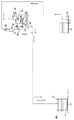
<システムの構成>
図1は本発明の一実施形態に係る逆洗システムAのシステム図である。逆洗システムAは、展示用海水槽1と濾過装置2との間で展示用海水槽1内の海水を循環させ、当該海水を濾過装置2で濾過する海水処理設備Bの、濾過装置2内の濾材を逆洗するシステムである。
<System configuration>
FIG. 1 is a system diagram of a backwash system A according to an embodiment of the present invention. The backwashing system A circulates the seawater in the exhibition seawater tank 1 between the exhibition seawater tank 1 and the filtration apparatus 2 and filters the seawater in the filtration apparatus 2 of the seawater treatment facility B that filters the seawater. This is a system for backwashing the filter medium.
海水処理設備Bは展示用海水槽1からの排海水(及び余剰海水)を制御弁59を介して濾過装置2へ供給するポンプ35を備える。ポンプ35に接続された流路には制御弁58が配設されており、制御弁58を開くと排海水及び余剰海水は泡沫分離装置3へ供給される。泡沫分離装置3は排海水から泡沫を分離する装置であり、排海水中の蛋白質、浮遊性懸濁物質を除去する。また、泡沫分離装置3にはオゾン発生装置3aが接続されており、オゾン発生装置3aにより発生するオゾンにより排海水の殺菌も行なう。泡沫分離装置3を通過した排海水は脱気装置4へ供給される。脱気装置4は排海水に対する脱気処理を行なう。
The seawater treatment facility B includes a
脱気装置4内の排海水はポンプ34により制御弁59を介して濾過装置2へ移送される。制御弁60は濾過装置2の逆洗時に開かれ、通常運転時には閉じられる。制御弁59を開くと排海水は、3方向制御弁61及び62を介して濾過装置2へ供給される。3方向制御弁61は流路R2−M1間、流路R2−M2間、流路M1−M2間のいずれかの接続関係に選択的に切替える。3方向制御弁62は流路R2−N1間、流路R2−N2間、流路N1−N2間のいずれかの接続関係に選択的に切替える。濾過装置2は2基の濾過ユニット2a及び2bを備える。濾過ユニット2a及び2bは排海水を濾過する濾材を内蔵する。濾過ユニット23a及び23bの濾過能力は濾過装置2の濾過ユニット2a及び2bよりも低いもので足りる。濾過装置2を通過した排海水は制御弁63を通過して展示用海水槽1へ還流する。制御弁63は濾過装置2の逆洗時には閉じられる。
The discharged seawater in the
逆洗システムAは、展示用海水槽1からの排海水を貯留する貯留槽10と、貯留槽10内の排海水を浄化する浄化設備20と、浄化設備20で浄化された排海水を逆洗水として濾過装置2に供給する逆洗水供給手段であるポンプ30と、逆洗システムAを制御する制御盤40と、を備える。本実施形態の場合、制御盤40は海水処理設備Bの制御も行なう。
The backwash system A includes a
貯留槽10は液体を収容可能な槽状をなし、貯留槽10内に貯留される排海水の液位を検知する液位センサ11と、空気の噴出口を複数有し、貯留槽10内に配設された曝気管12と、を備える。液位センサ11は例えば貯留槽10内の底部近傍の液圧を検知する圧力センサであり、当該液圧により貯留槽10内の排海水の液位を検知する。制御盤40は液位センサ11の検知結果を定期的に取得し、排海水の液位が一定以上低くなると、制御弁50を開いて展示用海水槽1からの排海水を貯留槽10内へ供給させる。本実施形態では制御弁50を開くことにより展示用海水槽1からの余剰海水も貯留槽10内へ供給される。曝気管12は不図示の曝気用ポンプから供給される圧縮空気を噴出し、貯留槽10内の排海水を攪拌する。これにより、貯留槽10内の排海水の腐敗を防止する。
The
貯留槽10内の排海水は貯留槽10の底部付近からポンプ31の作動により外部に排出可能となっており、排出された排海水はストレーナ13を通過して浄化設備20へ供給される。ポンプ31に接続された排海水の流路には制御弁51、52が配設されており、制御弁51を閉じて制御弁52を開くと排海水が制御弁52を通過して浄化設備20へ供給され、制御弁51を開いて制御弁52を閉じると排海水は制御弁51を通過して所定の処理が施されて下水へ放流される。
The discharged seawater in the
浄化設備20は貯留槽10内の排海水を濾過装置2の逆洗水として利用可能なように浄化する設備であり、本実施形態の場合、泡沫分離装置21と、脱気装置22と、濾過装置23と、を備える。泡沫分離装置21は排海水から泡沫を分離する装置であり、排海水中の蛋白質、浮遊性懸濁物質を除去する。また、泡沫分離装置21にはオゾン発生装置21aが接続されており、オゾン発生装置21aにより発生するオゾンにより排海水の殺菌も行なう。泡沫分離装置21を通過した排海水は脱気装置22へ供給される。脱気装置22は排海水に対する脱気処理を行なう。
The
脱気装置22内の排海水はポンプ32により移送される。ポンプ32に接続された排海水の流路には制御弁53、54が配設されており、制御弁53を開くと排海水が貯留槽10へ還流し、貯留槽10と浄化設備20(ここでは泡沫分離装置21及び脱気装置22)との間で、前記貯留槽内の排海水を循環させる。従って、ポンプ31及び32と制御弁52及び53とは循環手段として機能する。
The discharged seawater in the
制御弁54を開くと排海水は3方向制御弁55及び56を介して濾過装置23へ供給される。3方向制御弁55は流路R1−x1間、流路R1−x2間、流路x1−x2間のいずれかの接続関係に選択的に切替える。3方向制御弁56は流路R1−y1間、流路R1−y2間、流路y1−y2間のいずれかの接続関係に選択的に切替える。濾過装置23は2基の濾過ユニット23a及び23bを備える。濾過ユニット23a及び23bは排海水を濾過する濾材を内蔵する。濾過ユニット23a及び23bの濾過能力は濾過装置2の濾過ユニット2a及び2bよりも低いもので足りる。濾過装置23を通過した排海水は貯留槽15内に浄化された逆洗水として貯留される。
When the
貯留槽15内の逆洗水はポンプ30の作動により濾過装置2及び23の逆洗に用いられる。濾過装置2を逆洗するときは制御弁58を閉じ、濾過装置23を逆洗するときは制御弁59を開くことになる。ポンプ33は貯留槽15内の逆洗水を循環させるポンプであり、制御弁64を開き、ポンプ33を作動することで貯留槽15内の逆洗水が循環することになる。
The backwash water in the
次に、逆洗システムA及び海水処理設備Bの制御系について説明する。図2は逆洗システムA及び海水処理設備Bの制御系のブロック図である。逆洗システムA及び海水処理設備Bは制御盤40と、管理室等に設置され、制御盤40と通信可能なコンピュータ70と、を備える。
Next, the control system of the backwash system A and the seawater treatment facility B will be described. FIG. 2 is a block diagram of the control system of the backwash system A and the seawater treatment facility B. The backwash system A and the seawater treatment facility B include a
制御盤40はCPU41と、RAM42と、ROM43とを備える。ROM43には逆洗システムA及び海水処理設備Bの制御プログラム等が格納される。RAM42、ROM43は他の記憶手段も採用可能である。CPU41には入力インターフェース(I/F)44が接続されており、入力I/F44には操作パネル45、液位センサ11が接続されている。操作パネル45は操作者が制御盤40に対する各種の命令を行なうための操作を受け付ける。液位センサ11の検知結果は入力I/F44を介してCPU41が取得する。
The
CPU41には出力I/F46が接続されており、出力I/F46に接続されている、表示器47、各種装置(3、3a、4、21、21a、22)、制御弁50乃至63にそれぞれ制御命令を出力し、これらは制御命令に従って動作する。
An output I /
CPU41には通信I/F48が接続されており、コンピュータ70とのデータ通信を行なう。コンピュータ70は制御盤40に対して、自動運転・マニュアル運転の設定等の各種設定、逆洗システムA及び海水処理設備Bの動作指示、逆洗システムA及び海水処理設備Bの状態表示等を行なう。
A communication I /
<システムの動作>
<海水処理設備Bの通常運転>
図3は海水処理設備Bの通常運転時の動作説明図である。通常運転時には展示用海水槽1と濾過装置2との間で排海水(及び余浄海水)を循環させる。制御盤40は制御弁59、63を開く。また、3方向制御弁61は流路R2とM1とが接続されるように、3方向制御弁62は流路R2とN1とが接続されるように切替える。制御盤40がポンプ35を作動させることにより、展示用海水槽1からの排海水及び余剰海水は図3の矢印の方向に移送される。なお、制御弁58を開き、ポンプ34を作動することで排海水及び余剰海水が泡沫分離装置3、脱気装置4を通過し、その浄化が図られる。
<System operation>
<Normal operation of seawater treatment facility B>
FIG. 3 is an operation explanatory diagram of the seawater treatment facility B during normal operation. During normal operation, waste seawater (and surplus seawater) is circulated between the display seawater tank 1 and the filtration device 2. The
<濾過装置2の逆洗>
図4は濾過装置2の逆洗時の動作説明図である。濾過装置2の逆洗時に制御盤40は制御弁63を閉じ、制御弁60を開く。また、図4にて不図示の制御弁59、64は閉じる。本実施形態の場合、濾過装置2の逆洗は濾過ユニット2a、2bそれぞれ個別に行なう。まず、濾過ユニット2aの逆洗時について説明する。
<Backwashing of the filtration device 2>
FIG. 4 is an operation explanatory diagram of the filtration device 2 during backwashing. When the filtration device 2 is backwashed, the
制御盤40は3方向制御弁61を流路M1とM2とが接続されるように切替え、3方向制御弁62を流路R2とN1とが接続されるように切替える。ポンプ30を作動させると、貯留槽15内の逆洗水が図4で実線矢印で示すように、制御弁60⇒3方向制御弁62⇒濾過ユニット2b⇒濾過ユニット2a(逆洗される)⇒3方向制御弁61⇒流路M2、と流れて逆洗後の逆洗水が貯留槽10へ供給される。逆洗後の逆洗水は浄化されて再度逆洗水として用いられることになる。
The
次に、濾過ユニット2bの逆洗時について説明する。制御盤40は3方向制御弁61を流路R2とM1とが接続されるように切替え、3方向制御弁61を流路N1とN2とが接続されるように切替える。ポンプ30を作動させると、貯留槽15内の逆洗水が図4で実線並びに破線矢印で示すように、制御弁60⇒3方向制御弁61⇒濾過ユニット2a⇒濾過ユニット2b(逆洗される)⇒3方向制御弁62⇒流路N2、と流れて逆洗後の逆洗水が貯留槽10へ供給される。逆洗後の逆洗水は浄化されて再度逆洗水として用いられることになる。
Next, the backwashing of the
<排海水の再利用>
図5(a)及び(b)は貯留槽10内の排海水を浄化して逆洗水として再利用する場合の動作説明図である。まず、貯留槽10内の底部には浮遊性懸濁物質が滞留している可能性があるのでこれを浄化対象から排除すべく、浮遊性懸濁物質を排出する処理を行う。制御盤40は制御弁51を開き、制御弁52を閉じる。ポンプ31を作動することで貯留槽10内の浮遊性懸濁物質を含む排海水が図5(a)で矢印で示すようにストレーナ13、ポンプ31、制御弁51を通過して排出される。ポンプ31は浮遊性懸濁物質を排出する排出手段として機能することになる。排出された排海水は所定の処理が施されて下水へ放流される。ポンプ31を一定時間作動させ、浮遊性懸濁物質を排出する処理を継続する。
<Reuse of wastewater>
FIGS. 5A and 5B are operation explanatory views when the wastewater in the
浮遊性懸濁物質を排出する処理が終了すると排海水を浄化する処理を行う。制御盤40は制御弁51を閉じ、制御弁52乃至54を開く。また、3方向制御弁55は流路R1とx1とが接続されるように、3方向制御弁56は流路R1とY1とが接続されるように切替える。更に、制御弁57、64を開く。制御盤40はその後ポンプ31乃至33を作動させる。
When the process of discharging suspended suspended matter is completed, the process of purifying wastewater is performed. The
貯留槽10内の排海水は図5(b)で矢印で示すようにストレーナ13⇒ポンプ31⇒制御弁52⇒泡沫分離装置21⇒脱気装置22⇒ポンプ32と流れ、その一部は制御弁553を通過して貯留槽10内に還流され、排海水が循環される。残りは制御弁54、3方向制御弁55、56を通過して濾過装置23を通過し濾過される。浄化設備20による一連の処理で浄化された排海水は制御弁57を通過して貯留槽15に逆洗水として貯留される。貯留槽15内の逆洗水はポンプ33により制御弁64を通過して貯留槽15に還流され、循環される。
As shown by the arrow in FIG. 5B, the wastewater in the
<濾過装置23の逆洗>
図6は濾過装置23の逆洗時の動作説明図である。濾過装置23の逆洗においても貯留槽15の逆洗水を用いる。制御盤40は制御弁57を閉じ、制御弁58を開く。また、図6にて不図示の制御弁54、64は閉じる。本実施形態の場合、濾過装置2の逆洗の場合と同様、濾過ユニット23a、23bそれぞれ個別に行なう。まず、濾過ユニット23aの逆洗時について説明する。
<Backwashing of the
FIG. 6 is an explanatory view of the operation of the
制御盤40は3方向制御弁55を流路X1とX2とが接続されるように切替え、3方向制御弁56を流路R1とY1とが接続されるように切替える。ポンプ30を作動させると、貯留槽15内の逆洗水が図6で実線矢印で示すように、制御弁58⇒3方向制御弁56⇒濾過ユニット23b⇒濾過ユニット23a(逆洗される)⇒3方向制御弁55⇒流路X2と流れて逆洗後の逆洗水に所定の処理が施されて下水に放流される。
The
次に、濾過ユニット23bの逆洗時について説明する。制御盤40は3方向制御弁55を流路R1とX1とが接続されるように切替え、3方向制御弁56を流路Y1とY2とが接続されるように切替える。ポンプ30を作動させると、貯留槽15内の逆洗水が図6で実線並びに破線矢印で示すように、制御弁58⇒3方向制御弁55⇒濾過ユニット23a⇒濾過ユニット23b(逆洗される)⇒3方向制御弁56⇒流路Y2、と流れて逆洗後の逆洗水に所定の処理が施されて下水に放流される。
Next, the backwashing of the
<システムの効果>
逆洗システムAでは展示用海水槽1の排海水を浄化して逆洗水として再利用することができる。従って、ランニングコストを低減することができる。逆洗水が海水なのでバクテリアの減少を抑制し、逆洗後の濾過能力の低減を防止することができる。また、展示用海水槽1からの余浄海水、濾過装置2の逆洗時の排海水(逆洗後の逆洗水)が貯留槽10に貯留され、逆洗水として再利用される。従ってランニングコストを更に低減することができる。
<System effect>
In the backwash system A, the wastewater from the exhibition seawater tank 1 can be purified and reused as backwash water. Therefore, the running cost can be reduced. Since the backwash water is seawater, the reduction of bacteria can be suppressed, and the reduction of filtration capacity after backwash can be prevented. In addition, surplus seawater from the exhibition seawater tank 1 and wastewater seawater (backwash water after backwashing) at the time of backwashing of the filtration device 2 are stored in the
また、浄化設備20による排海水の浄化に先立ち、排海水の前処理として浮遊性懸濁物質が排海水から除去されるので(図5(a))、排海水の浄化効率を高めることができる。浄化設備20は泡沫分離装置21と、脱気装置22と、濾過装置23と、を備えるので、逆洗水としてより好適な海水が得られる。更に、貯留槽10と泡沫分離装置21及び脱気装置22との間では排海水が循環されるので、繰り返し浄化され、処理能力の小さなより小規模の設備でも排海水をより効果的に浄化できる。
In addition, since the suspended suspended solids are removed from the wastewater as a pretreatment of the wastewater prior to purification of the wastewater by the purification facility 20 (FIG. 5A), the purification efficiency of the wastewater can be increased. . Since the
A 逆洗システム
B 海水処理設備
1 展示用海水槽
2 濾過装置
10 貯留槽
20 浄化設備
30〜35 ポンプ
50〜64 制御弁
A Backwash system B Seawater treatment facility 1 Seawater tank 2 for
Claims (5)
前記展示用海水槽からの排海水を貯留する貯留槽と、
前記貯留槽内の排海水を浄化する浄化設備と、
前記浄化設備で浄化された前記排海水を逆洗水として前記濾過装置に供給する逆洗水供給手段と、を備えたことを特徴とする逆洗システム。 A backwash system for backwashing the filter medium in the filtration device of a seawater treatment facility for circulating seawater in the exhibition seawater tank between the exhibition seawater tank and the filtration device and filtering the seawater by the filtration device In
A storage tank for storing wastewater from the exhibition seawater tank;
Purification equipment for purifying wastewater in the storage tank;
A backwashing system comprising: backwashing water supply means for feeding the wastewater purified by the purification equipment to the filtration device as backwashing water.
前記展示用海水槽からの余浄海水、又は、前記濾過装置の逆洗時の排海水の少なくともいずれかが貯留されることを特徴とする請求項1に記載の逆洗システム。 In the storage tank,
The backwashing system according to claim 1, wherein at least one of the remaining purified seawater from the exhibition seawater tank and the drained seawater during backwashing of the filtration device is stored.
前記排海水から泡沫を分離する泡沫分離装置と、前記排海水を脱気する脱気装置と、前記排海水を濾過する濾過器と、を含むことを特徴とする請求項1乃至3のいずれかに記載の逆洗システム。 The purification equipment is
4. The apparatus according to claim 1, further comprising: a foam separation device that separates foam from the wastewater, a deaeration device that degass the wastewater, and a filter that filters the wastewater. Backwash system as described in.
Priority Applications (1)
| Application Number | Priority Date | Filing Date | Title |
|---|---|---|---|
| JP2005166009A JP4754884B2 (en) | 2005-06-06 | 2005-06-06 | Backwash system |
Applications Claiming Priority (1)
| Application Number | Priority Date | Filing Date | Title |
|---|---|---|---|
| JP2005166009A JP4754884B2 (en) | 2005-06-06 | 2005-06-06 | Backwash system |
Publications (2)
| Publication Number | Publication Date |
|---|---|
| JP2006334568A true JP2006334568A (en) | 2006-12-14 |
| JP4754884B2 JP4754884B2 (en) | 2011-08-24 |
Family
ID=37555557
Family Applications (1)
| Application Number | Title | Priority Date | Filing Date |
|---|---|---|---|
| JP2005166009A Active JP4754884B2 (en) | 2005-06-06 | 2005-06-06 | Backwash system |
Country Status (1)
| Country | Link |
|---|---|
| JP (1) | JP4754884B2 (en) |
Cited By (3)
| Publication number | Priority date | Publication date | Assignee | Title |
|---|---|---|---|---|
| JP2008178382A (en) * | 2006-12-25 | 2008-08-07 | Ship & Ocean Foundation | On-land culturing system of fishes and shellfishes by utilizing transporting container |
| JP2016153105A (en) * | 2015-02-20 | 2016-08-25 | 三浦工業株式会社 | Ballast water treatment device |
| JP7390912B2 (en) | 2020-02-03 | 2023-12-04 | オルガノ株式会社 | Foam separator and breeding equipment equipped with the same |
Citations (7)
| Publication number | Priority date | Publication date | Assignee | Title |
|---|---|---|---|---|
| JPH07255321A (en) * | 1994-03-18 | 1995-10-09 | Chowa Kensui Kyodo Kumiai | Suspension removing device and water cleaning device and pisciculture device with no water exchange using these devices |
| JPH0823821A (en) * | 1994-07-18 | 1996-01-30 | Daiki Gomme Kogyo Kk | Sterilizing purifier for raising water |
| JPH1066963A (en) * | 1996-02-16 | 1998-03-10 | Yamaha Motor Co Ltd | Pressure-type circulatory filter |
| JPH10178966A (en) * | 1996-12-24 | 1998-07-07 | Shinei Sangyo Kk | Water processor for breeding fish or the like |
| JP2002336614A (en) * | 2001-05-11 | 2002-11-26 | Hitachi Zosen Corp | Fresh water and seawater back washing and filtering system for seawater filtering device in water treatment facility of aquarium or the like |
| JP2003092953A (en) * | 2001-09-21 | 2003-04-02 | Rikujo Yoshoku Kogaku Kenkyusho:Kk | Circulating filtration culture system |
| JP2003200007A (en) * | 2002-01-11 | 2003-07-15 | Hitachi Plant Eng & Constr Co Ltd | Water treatment apparatus |
-
2005
- 2005-06-06 JP JP2005166009A patent/JP4754884B2/en active Active
Patent Citations (7)
| Publication number | Priority date | Publication date | Assignee | Title |
|---|---|---|---|---|
| JPH07255321A (en) * | 1994-03-18 | 1995-10-09 | Chowa Kensui Kyodo Kumiai | Suspension removing device and water cleaning device and pisciculture device with no water exchange using these devices |
| JPH0823821A (en) * | 1994-07-18 | 1996-01-30 | Daiki Gomme Kogyo Kk | Sterilizing purifier for raising water |
| JPH1066963A (en) * | 1996-02-16 | 1998-03-10 | Yamaha Motor Co Ltd | Pressure-type circulatory filter |
| JPH10178966A (en) * | 1996-12-24 | 1998-07-07 | Shinei Sangyo Kk | Water processor for breeding fish or the like |
| JP2002336614A (en) * | 2001-05-11 | 2002-11-26 | Hitachi Zosen Corp | Fresh water and seawater back washing and filtering system for seawater filtering device in water treatment facility of aquarium or the like |
| JP2003092953A (en) * | 2001-09-21 | 2003-04-02 | Rikujo Yoshoku Kogaku Kenkyusho:Kk | Circulating filtration culture system |
| JP2003200007A (en) * | 2002-01-11 | 2003-07-15 | Hitachi Plant Eng & Constr Co Ltd | Water treatment apparatus |
Cited By (3)
| Publication number | Priority date | Publication date | Assignee | Title |
|---|---|---|---|---|
| JP2008178382A (en) * | 2006-12-25 | 2008-08-07 | Ship & Ocean Foundation | On-land culturing system of fishes and shellfishes by utilizing transporting container |
| JP2016153105A (en) * | 2015-02-20 | 2016-08-25 | 三浦工業株式会社 | Ballast water treatment device |
| JP7390912B2 (en) | 2020-02-03 | 2023-12-04 | オルガノ株式会社 | Foam separator and breeding equipment equipped with the same |
Also Published As
| Publication number | Publication date |
|---|---|
| JP4754884B2 (en) | 2011-08-24 |
Similar Documents
| Publication | Publication Date | Title |
|---|---|---|
| US9908800B2 (en) | System and method for wastewater treatment | |
| KR20170016867A (en) | System and method for cleaning and sterilizing a water flow | |
| JP5982626B2 (en) | Water purification system | |
| JP5111757B2 (en) | Filtration unit | |
| KR101334330B1 (en) | Treatment System and Method for Ballast Water | |
| JP2006248510A (en) | Ballast water purifying device and vessel with the same | |
| JP2006297376A (en) | Method for cleaning separation membrane | |
| EA029732B1 (en) | Underwater water treatment unit and method for cleaning said unit | |
| KR101437218B1 (en) | Rainwater recycling system for ship | |
| JP4754884B2 (en) | Backwash system | |
| JP2007130563A (en) | Utilization system of ballast water | |
| JP2014008439A (en) | Membrane separation type water treatment apparatus and method for cleaning water treatment separation membrane | |
| JP4557851B2 (en) | Anaerobic water treatment device | |
| JP2007014902A (en) | Desalination apparatus and washing method of pretreatment membrane of desalination apparatus | |
| WO2020240666A1 (en) | Membrane separation activated sludge system and membrane cleaning device | |
| JP2006043705A (en) | Anaerobic water treatment apparatus | |
| JP4358174B2 (en) | Anaerobic water treatment device | |
| SE534449C2 (en) | Cleaning unit for cleaning a ballast water treatment system | |
| JP2008183513A (en) | Water purifying apparatus | |
| US20050115906A1 (en) | Water conditioning system | |
| JP5985914B2 (en) | Control device for chemical solution circulation in membrane treatment equipment | |
| JP6029904B2 (en) | Membrane filtration system and operation control method thereof | |
| JP2003265907A (en) | Filament-used filtration apparatus | |
| WO2007076611A1 (en) | Sand filter cleaning apparatus and method thereof | |
| JP2007137260A (en) | Ballast water tank structure, ballast water manufacturing device, and manufacturing method of ballast water |
Legal Events
| Date | Code | Title | Description |
|---|---|---|---|
| A621 | Written request for application examination |
Free format text: JAPANESE INTERMEDIATE CODE: A621 Effective date: 20080215 |
|
| A131 | Notification of reasons for refusal |
Free format text: JAPANESE INTERMEDIATE CODE: A131 Effective date: 20110221 |
|
| A521 | Request for written amendment filed |
Free format text: JAPANESE INTERMEDIATE CODE: A523 Effective date: 20110408 |
|
| TRDD | Decision of grant or rejection written | ||
| A01 | Written decision to grant a patent or to grant a registration (utility model) |
Free format text: JAPANESE INTERMEDIATE CODE: A01 Effective date: 20110513 |
|
| A01 | Written decision to grant a patent or to grant a registration (utility model) |
Free format text: JAPANESE INTERMEDIATE CODE: A01 |
|
| A61 | First payment of annual fees (during grant procedure) |
Free format text: JAPANESE INTERMEDIATE CODE: A61 Effective date: 20110526 |
|
| FPAY | Renewal fee payment (event date is renewal date of database) |
Free format text: PAYMENT UNTIL: 20170603 Year of fee payment: 6 |
|
| R150 | Certificate of patent or registration of utility model |
Ref document number: 4754884 Country of ref document: JP Free format text: JAPANESE INTERMEDIATE CODE: R150 Free format text: JAPANESE INTERMEDIATE CODE: R150 |
|
| R250 | Receipt of annual fees |
Free format text: JAPANESE INTERMEDIATE CODE: R250 |