JP2006333741A - Implement controller of tractor - Google Patents
Implement controller of tractor Download PDFInfo
- Publication number
- JP2006333741A JP2006333741A JP2005160010A JP2005160010A JP2006333741A JP 2006333741 A JP2006333741 A JP 2006333741A JP 2005160010 A JP2005160010 A JP 2005160010A JP 2005160010 A JP2005160010 A JP 2005160010A JP 2006333741 A JP2006333741 A JP 2006333741A
- Authority
- JP
- Japan
- Prior art keywords
- draft
- spool
- shaft
- operating
- relay
- Prior art date
- Legal status (The legal status is an assumption and is not a legal conclusion. Google has not performed a legal analysis and makes no representation as to the accuracy of the status listed.)
- Granted
Links
Images


Abstract
Description
本発明は、トラクタの後部に昇降自在に装着された作業機のポジション制御及び/又はドラフト制御を行うトラクタの作業機制御装置に関するものである。 The present invention relates to a tractor work machine control device that performs position control and / or draft control of a work machine mounted on a rear portion of a tractor so as to be movable up and down.
従来、トラクタの作業機制御装置として、単一の制御弁を使用して、トラクタの後部に昇降自在に装着された作業機のポジション制御及び/又はドラフト制御を行うようにしたものが、特開平1−148107号公報、特開平1−148109号公報にて開示されている。
このトラクタの作業機制御装置は、車体に装着された作業機を昇降させる油圧式昇降装置と、スプールを中立位置から作動させることで作業機を昇降させるように前記油圧式昇降装置に対する圧油の流れを切り換える制御弁と、一端側を支点とする揺動によって前記制御弁のスプールを作動させるポジション用スプール作動レバーと、このポジション用スプール作動レバーの一端側を支点とする揺動量に比例して作業機を昇降させるべく作業機の昇降量をフィードバックさせてポジション用スプール作動レバーを他端側を支点として揺動させることでスプールを中立位置に戻すポジションフィードバック機構と、作業機を所望の昇降位置に操作するポジション操作レバーの操作によって軸心回りに回動することによりポジション用スプール作動レバーを一端側を支点として揺動させるポジション作動軸と、作業機に設定以上の牽引負荷が作用したときに一端側を支点として揺動することでスプールを作動させることにより作業機を上昇させるドラフト用スプール作動レバーと、ドラフト操作レバーの操作によって軸心回りに回動して作業機を上昇させるべき前記牽引負荷を設定するドラフト作動軸と、ポジション作動軸とポジション用スプール作動レバーとを連動連結するポジション用リンク機構と、ドラフト作動軸とドラフト用スプール作動レバーとを連動連結するドラフト用リンク機構とを備えている。
The tractor work implement control device includes a hydraulic lift device that lifts and lowers a work implement mounted on a vehicle body, and a hydraulic oil for the hydraulic lift device that lifts the work implement by operating a spool from a neutral position. A control valve for switching the flow, a spool operating lever for position that operates the spool of the control valve by swinging with one end side as a fulcrum, and a swing amount with one end side of the spool operating lever for position as a fulcrum A position feedback mechanism for returning the spool to the neutral position by feeding back the lifting amount of the working machine and swinging the position spool operating lever with the other end as a fulcrum in order to raise and lower the working machine, and the desired lifting position of the working machine The position spool lever can be rotated by rotating the position operation lever. A position operating shaft that swings the lever with one end as a fulcrum, and a draft that raises the work implement by operating the spool by swinging with one end as a fulcrum when a traction load greater than the setting acts on the work implement The spool operating lever, the draft operating shaft that rotates around the shaft center by the operation of the draft operating lever and sets the traction load that should raise the work implement, and the position operating shaft and the position spool operating lever are linked to each other And a draft link mechanism for interlockingly connecting the draft operating shaft and the draft spool operating lever.
前記従来のトラクタの作業機制御装置にあっては、ポジション作動軸とポジション用スプール作動レバーとを連動連結するポジション用リンク機構、及び、ドラフト作動軸とドラフト用スプール作動レバーとを連動連結するドラフト用リンク機構の構造が複雑であり、部品点数、組立工数が多いという問題がある。
そこで、本発明は、前記問題点に鑑みて、構造の簡素化を図ったトラクタの作業機制御装置を提供することを目的とする。
In the conventional work machine control device for a tractor, a position link mechanism for interlockingly connecting the position operating shaft and the position spool operating lever, and a draft for interlockingly connecting the draft operating shaft and the draft spool operating lever. There is a problem that the structure of the link mechanism is complicated, and the number of parts and assembly man-hours are large.
In view of the above problems, an object of the present invention is to provide a work machine control device for a tractor with a simplified structure.
前記技術的課題を解決するために本発明が講じた技術的手段は、車体に装着された作業機を昇降させる油圧式昇降装置と、スプールを中立位置から作動させることで作業機を昇降させるように前記油圧式昇降装置に対する圧油の流れを切り換える制御弁と、一端側を支点とする揺動によって前記制御弁のスプールを作動させるポジション用スプール作動レバーと、このポジション用スプール作動レバーの一端側を支点とする揺動量に比例して作業機を昇降させるべく作業機の昇降量をフィードバックさせてポジション用スプール作動レバーを他端側を支点として揺動させることでスプールを中立位置に戻すポジションフィードバック機構と、軸心回りに回動させることによりポジション用スプール作動レバーを一端側を支点として揺動させるポジション作動軸と、作業機に設定以上の牽引負荷が作用したときに一端側を支点として揺動することでスプールを作動させることにより作業機を上昇させるドラフト用スプール作動レバーとを備えたトラクタの作業機制御装置において、前記ドラフト用スプール作動レバーを他端側を支点として揺動させることにより作業機を上昇させるべき前記牽引負荷を設定可能とすると共に、軸心回りに回動させることによりドラフト用スプール作動レバーを他端側を支点として揺動させるドラフト作動軸を備え、このドラフト作動軸又は前記ポジション作動軸の一方の作動軸を筒体で構成し且つ他方の作動軸を該筒体内に同心状に挿通したことを特徴とする。 The technical means taken by the present invention in order to solve the technical problem is to lift and lower the work implement by operating the spool from the neutral position and a hydraulic lift device that raises and lowers the work implement mounted on the vehicle body. A control valve for switching the flow of pressure oil to the hydraulic lifting device, a position spool operating lever for operating the spool of the control valve by swinging with one end side as a fulcrum, and one end side of the position spool operating lever Position feedback for returning the spool to the neutral position by feeding back the lifting / lowering amount of the work implement in order to raise / lower the work implement in proportion to the swing amount with the other end side as the fulcrum, The position spool operating lever is swung about one end side as a fulcrum by rotating around the mechanism and the axis. A tractor equipped with a transition operating shaft and a draft spool operating lever that lifts the working machine by operating the spool by swinging with one end side as a fulcrum when a traction load greater than the setting acts on the working machine In the work implement control device, the draft spool operating lever can be set with the other end side as a fulcrum to enable setting of the traction load to raise the work implement, and by rotating the draft spool around the axis And a draft operating shaft for swinging the spool operating lever with the other end side as a fulcrum. One operating shaft of the draft operating shaft or the position operating shaft is formed of a cylinder, and the other operating shaft is disposed in the cylinder. It is characterized by being inserted concentrically.
また、他の技術的手段は、車体に装着された作業機を昇降させる油圧式昇降装置と、スプールを中立位置から作動させることで作業機を昇降させるように前記油圧式昇降装置に対する圧油の流れを切り換える制御弁と、一端側を支点とする揺動によって前記制御弁のスプールを作動させるポジション用スプール作動レバーと、このポジション用スプール作動レバーの一端側を支点とする揺動量に比例して作業機を昇降させるべく作業機の昇降量をフィードバックさせてポジション用スプール作動レバーを他端側を支点として揺動させることでスプールを中立位置に戻すポジションフィードバック機構と、作業機に設定以上の牽引負荷が作用したときに一端側を支点として揺動することでスプールを作動させることにより作業機を上昇させるドラフト用スプール作動レバーとを備えたトラクタの作業機制御装置において、前記ドラフト用スプール作動レバーが一端側を支点として揺動した際に、スプール側に設けた接当部に接当して該接当部を押動することにより作業機が上昇するようにスプールを作動させる押動部材をドラフト用スプール作動レバーに連結し、ドラフト用スプール作動レバーを他端側を支点として揺動させることによって前記押動部材の位置を調整することにより作業機を上昇させるべき前記牽引負荷を設定可能としたことを特徴とする。 Further, another technical means includes a hydraulic lifting device that lifts and lowers the working machine mounted on the vehicle body, and pressure oil for the hydraulic lifting device so as to lift and lower the working machine by operating the spool from the neutral position. A control valve for switching the flow, a spool operating lever for position that operates the spool of the control valve by swinging with one end side as a fulcrum, and a swing amount with one end side of the spool operating lever for position as a fulcrum A position feedback mechanism that returns the spool to the neutral position by feeding back the lifting amount of the working machine and swinging the position spool operating lever with the other end as a fulcrum in order to raise and lower the working machine, and pulling more than set to the working machine When the load is applied, the work implement is lifted by operating the spool by swinging around one end side as a fulcrum. In a tractor work machine control device having a ft spool operating lever, when the draft spool operating lever swings around one end side as a fulcrum, it comes into contact with a contact portion provided on the spool side. The pushing member for operating the spool so that the working machine is raised by pushing this portion is connected to the draft spool operating lever, and the draft spool operating lever is swung around the other end as a fulcrum. By adjusting the position of the pushing member, it is possible to set the traction load for raising the work implement.
また、ポジション作動軸にポジション第1中継アームを設け、作業機を所望の昇降位置に操作するポジション操作手段の操作によって軸心回りに回動するポジション中継軸を設け、このポジション中継軸にポジション第2中継アームを設け、このポジション第2中継アームに、作業機を上昇させるようにポジション操作手段を操作した際に、前記ポジション第1中継アームに接当してこれを押動することによりポジション作動軸を回動させて作業機を上昇させるように制御弁を切り換える押動部を設け、作業機を上昇させるようにポジション用スプール作動レバーが動作して該ポジション用スプール作動レバーからの動作によってポジション作動軸が回動した場合には、ポジション中継第1アームが押動部に対して離反するように構成すると共に、作業機を下降させるようにポジション操作手段を操作した際には、作業機を下降させるように制御弁を切り換える方向にスプールを付勢する付勢手段の付勢力によってポジション第1中継アームを押動部に追従させるように構成するのがよい。 The position operating shaft is provided with a position first relay arm, and a position relay shaft that is rotated around the axis by operation of a position operating means for operating the work machine to a desired lift position is provided. Two relay arms are provided, and when the position operating means is operated to raise the work implement to this position second relay arm, the position is operated by contacting and pushing the position first relay arm A pusher that switches the control valve to raise the work implement by rotating the shaft is provided, and the position spool operating lever operates to raise the work implement, and the position is determined by the operation from the position spool operating lever. When the operating shaft is rotated, the position relay first arm is configured to be separated from the pushing portion. In addition, when the position operating means is operated to lower the work implement, the position first relay arm is moved by the biasing force of the biasing means that biases the spool in the direction of switching the control valve so as to lower the work implement. It is good to comprise so that it may follow a pushing part.
また、ドラフト作動軸にドラフト第1中継アームを設け、作業機を上昇させるべき前記牽引負荷を設定するドラフト操作手段の操作によって軸心回りに回動するドラフト中継軸を設け、このドラフト中継軸に、該ドラフト中継軸の回動によって前記ドラフト作動軸を回動させるように前記ドラフト第1中継アームに係合するドラフト第2中継アームを設け、前記ポジション中継軸及びドラフト中継軸が取り付けられ且つ車体側に取り付けられる取付フレームを備え、この取付フレームにポジション中継軸及びドラフト中継軸を組み付けた状態で該取付フレームを車体側に取り付けることにより、ポジション第2中継アームがポジション第1中継アームに係合し且つドラフト第2中継アームがドラフト第1中継アームに係合するように構成されていてもよい。 Also, a draft first relay arm is provided on the draft operating shaft, and a draft relay shaft that rotates around the axis by the operation of the draft operating means for setting the traction load to raise the work implement is provided. A draft second relay arm that engages with the first draft relay arm is provided so that the draft operation shaft is rotated by rotation of the draft relay shaft, the position relay shaft and the draft relay shaft are mounted, and the vehicle body The position second relay arm is engaged with the position first relay arm by attaching the mounting frame to the vehicle body with the position relay shaft and the draft relay shaft assembled to the mounting frame. And the draft second relay arm is configured to engage the draft first relay arm. It can have.
本発明によれば、トラクタの後部に昇降自在に装着された作業機のポジション制御及び/又はドラフト制御を行う作業機制御装置の簡素化を図ることができる。 ADVANTAGE OF THE INVENTION According to this invention, the simplification of the working machine control apparatus which performs position control and / or draft control of the working machine with which the rear part of the tractor was attached so that raising / lowering was possible can be achieved.
以下、本発明の実施の形態を図面を参照して説明する。
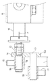
図2において、1はトラクタの車体の後部を構成するミッションケースであり、このミッションケース1の上面側には、該ミッションケース1の上面に形成された開口部を施蓋するように取り付けられた取付体2が設けられている。
なお、トラクタの車体は前部のエンジンと、このエンジンの後部にフライホイールハウジングを介して連結されるクラッチハウジングと、このクラッチハウジングの後部に連結されるミッションケース1とで主構成される。
Hereinafter, embodiments of the present invention will be described with reference to the drawings.
In FIG. 2, reference numeral 1 denotes a transmission case that forms the rear part of the tractor body. The transmission case 1 is attached to the upper surface of the transmission case 1 so as to cover an opening formed on the upper surface of the transmission case 1. A
The vehicle body of the tractor mainly includes a front engine, a clutch housing connected to the rear part of the engine via a flywheel housing, and a transmission case 1 connected to the rear part of the clutch housing.
この取付体2の後部には、トップリンク取付ブラケット3を取り付けるためのブラケット取付部4が設けられ、このブラケット取付部4に左右方向の軸心を有するトーションバー(負荷検知手段)5を介してトップリンク取付ブラケット3が取り付けられ、このトップリンク取付ブラケット3に設けられた取付孔6の1つに三点リンク機構のトップリンクの一端側(トラクタ側)が選択的に枢支連結される。
三点リンク機構の左右ロワーリンクの一端側(トラクタ側)は、ミッションケース1の側面の後下部に設けられるロワーリンク取付部に枢支連結され、トップリンク及び左右ロワーリンクの他端側(作業機側)は、プラウ等の作業機のフレームに枢支連結され、該作業機がトラクタの車体の後部に三点リンク機構を介して昇降自在に装着される。
A bracket mounting portion 4 for mounting the top link mounting bracket 3 is provided at the rear portion of the
One end side (tractor side) of the left and right lower links of the three-point link mechanism is pivotally connected to a lower link mounting portion provided at the rear lower part of the side surface of the mission case 1, and the other end side of the top link and left and right lower links (work The machine side is pivotally connected to a frame of a work machine such as a plow, and the work machine is mounted on the rear part of the vehicle body of the tractor so as to be movable up and down via a three-point link mechanism.
前記取付体2の左右両側面の前後方向中途部には、リフトアーム枢支部7が設けられ、左右各リフトアーム枢支部7にリフトアーム8の基部が左右方向の軸心回りに回動自在に枢支され、左右のリフトアーム8の先端側にはリフトロッドの一端側が枢支連結され、左右各リフトロッドの他端側はロワーリンクの長手方向中途部に枢支連結される。
また、ミッションケース1の後方側には左右一対の昇降シリンダ9が配置され、左右昇降シリンダ9の一端側(上端側、ピストンロッド)は左右リフトアーム8の中途部に枢支連結され、この昇降シリンダ9の他端側(下端側、シリンダ本体のピストン頂部側)はミッションケース1の側面の後下部に設けられるシリンダ取付部に枢支連結される。
Lift arm pivots 7 are provided in the front-rear halfway portions of the left and right side surfaces of the
In addition, a pair of left and right lifting cylinders 9 are arranged on the rear side of the mission case 1, and one end side (upper end side, piston rod) of the left and right lifting cylinders 9 is pivotally connected to the middle part of the left and
この左右昇降シリンダ9を伸縮(ピストンロッドを突出・退避)させることにより左右のリフトアーム8が回動軸心回りに上下揺動すると共に、この左右リフトアーム8が上下に揺動することにより、左右のロワーリンクがトラクタ側の枢支部回りに上下に揺動動作し、これによって作業機が昇降するように構成されている。
前記昇降シリンダ9は単動式の油圧シリンダによって構成されており、該昇降シリンダ9のシリンダ本体のピストン頂部側に圧油を供給してピストンロッドを上方側に突出させる(昇降シリンダ9を伸張させる)ことによりリフトアーム8が上方回動して作業機が上昇し、昇降シリンダ9のシリンダ本体のピストン頂部側の圧油を排出してピストンロッドを下方側に退避させる(昇降シリンダ9が収縮する)ことによりリフトアーム8が下方回動して作業機が自重で下降し、昇降シリンダ9に対する圧油の供給・排出を停止させることによりリフトアーム8が停止して作業機が停止するように構成されている。
By extending and retracting the left and right lifting cylinder 9 (projecting and retracting the piston rod), the left and
The elevating cylinder 9 is constituted by a single-acting hydraulic cylinder, and pressure oil is supplied to the piston top side of the cylinder body of the elevating cylinder 9 so that the piston rod protrudes upward (the elevating cylinder 9 is extended). Thus, the
前記取付体2とリフトアーム8とリフトロッドと昇降シリンダ9等とで作業機を昇降させる油圧式昇降装置10を主構成している。
前記取付体2の内側(下面側)の前部には前記昇降シリンダ9を制御する制御弁11が配置されている。
この制御弁11は、直動スプール形の3位置切換弁によって構成され、スプール12が前方に突出状するように且つ前後方向に摺動自在に設けられており、スプール12の前後方向の摺動により、昇降シリンダ9に対する圧油の供給・排出を停止する中立位置と、昇降シリンダ9のシリンダ本体のピストン頂部側に圧油を供給する上昇位置と、昇降シリンダ9のシリンダ本体のピストン頂部側から圧油を排出する下降位置とに該スプール12が切り換えられて制御弁11が切換操作されるように構成されており、スプール12は、作業機を下降(昇降シリンダ9を収縮又はリフトアーム8を下方回動)させるように制御弁11を切り換える方向にバネによって付勢されている。
The
A
The
本実施の形態では、スプール12を中立位置から押し込むことにより作業機を上昇させるように制御弁11が切り換えられ(スプール12が上昇位置に切り換えられ)、スプール12を中立位置から引き出すことにより作業機を下降させるように制御弁11が切り換えられ(スプール12が下降位置に切り換えられ)、スプール12はバネの付勢力Fによって引き出される方向に付勢されている。
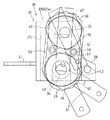
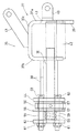
図1、図3、図6、図7に示すように、制御弁11のスプール12の先端側(前端側)には取付ブロック13が取付固定され、この取付ブロック13の前面側には、板材等からなる取付部材14が固定され、この取付部材14はスプール12先端から下方に突出していると共に、取付部材14の前面側には、前後方向の軸心を有する上下一対の支軸16,17が設けられている。
In the present embodiment, the
As shown in FIGS. 1, 3, 6, and 7, a
上側の支軸16はスプール12の軸心と同心状に設けられ、この上側の支軸16にはポジション用継手ブロック18が軸心回りに回動自在で且つ軸心方向(前後方向)移動不能に外嵌されており、このポジション用継手ブロック18の上面側には、上下方向の軸心を有するポジション用継手ピン19が固定されている。
また、下側の支軸17は上側の支軸16の真下位置に該上側の支軸16と平行状に設けられ、この下側の支軸17にはドラフト用継手ブロック(押動部材)20が軸心回りに回動自在で且つ軸心方向(前後方向)移動自在に外嵌されており、このドラフト用継手ブロック20の下面側には、上下方向の軸心を有するドラフト用継手ピン21が固定されている。
The
The
前記ポジション用継手ピン19には、左右方向に配置されたポジション用スプール作動レバー22の軸方向中途部が枢支連結されていて、該ポジション用スプール作動レバー22の左右両側がポジション用継手ピン19回りに前後揺動自在で且つ上下揺動自在となるようにポジション用スプール作動レバー22が支持されている。
また、ドラフト用継手ピン21には、左右方向に配置されたドラフト用スプール作動レバー23の軸方向中途部が枢支連結されていて、該ドラフト用スプール作動レバー23の左右両側がドラフト用継手ピン21回りに前後揺動自在で且つ上下揺動自在となるようにドラフト用スプール作動レバー23が支持されている。
The
The draft
これらポジション用スプール作動レバー22及びドラフト用スプール作動レバー23の左右方向(軸方向)両端部には、それぞれ球継手部22a,23aが設けられている。
前記制御弁11のスプール12先端側の左右一側(右側)には、ポジション作動軸24とドラフト作動軸25とが配置されている。
これらポジション作動軸24とドラフト作動軸25とは、ともに左右方向の軸心を有し、本実施の形態では、ドラフト作動軸25は筒体によって構成され、取付体2の右側の壁部を左右方向に貫通して形成された支持孔26に挿通されていて該支持孔26に軸心回りに回動自在に支持されており、ポジション作動軸24はドラフト作動軸25に挿通されていて該ドラフト作動軸25に軸心回りに相対回動自在に支持されており、これらポジション作動軸24とドラフト作動軸25とは同心状に配置されている。
Ball
A
Both the
なお、ポジション作動軸24を筒体とし、ドラフト作動軸25を該筒体に挿通するようにしてもよい。
ドラフト作動軸25の左右方向内端側は支持孔26から左右方向に突出していると共に、該ドラフト作動軸25の左右方向内端部には径方向下方側に突出状のドラフト作動アーム27が固定され、このドラフト作動アーム27の先端側(突出端部側)はドラフト用スプール作動レバー23の右端側の球継手部23aに球継手構造によって連動連結されている。
The
A left and right inner end of the
また、ドラフト作動軸25の左右方向外端側は支持孔26から左右方向に突出しており、このドラフト作動軸25の左右方向外端側には径方向上方側に突出状にドラフト第1中継アーム28が固定され、このドラフト第1中継アーム28の先端側(突出端部側)には左右方向の軸心を有する係合ピン29が左右方向外方に突出状に固定されている。
ポジション作動軸24の左右方向内端側はドラフト作動軸25から左右方向に突出しており、このポジション作動軸24の左右方向内端側には径方向上方側に突出状のポジション作動アーム31が固定され、このポジション作動アーム31の先端側(突出端部側)はポジション用スプール作動レバー22の右端側の球継手部22aに球継手構造によって連動連結されている。
In addition, the left and right outer end sides of the
The inner side of the
また、ポジション作動軸24の左右方向外端側はドラフト作動軸25から左右方向に突出しており、このポジション作動軸24の左右方向外端側にはボス32が取付固定され、このボス32に径方向上方側に突出状にポジション第1中継アーム33が固定されている。
図3及び図4に示すように、ポジション作動軸24及びドラフト作動軸25の右方には、左右方向の軸心を有するポジション中継軸34が同心状として配置され、このポジション中継軸34の上方には左右方向の軸心を有するドラフト中継軸35が平行状として配置され、これらポジション中継軸34及びドラフト中継軸35は取付体2の右側部にボルトによって着脱自在に取付固定された取付フレーム36に取り付けられて軸心回りに回動自在に支持されている。
The left and right outer ends of the
As shown in FIGS. 3 and 4, a
図4、図8、図9に示すように、取付フレーム36は、メインフレーム37と上下一対の支持筒38とを有し、メインフレーム37は、左右方向に間隔をおいて対向配置された内外側壁37a,37bと、これら内側壁37aと外側壁37bとの後縁側を連結する後壁37cとから平面視コ字形に形成されている。
このメインフレーム37は、内側壁37aの前下部の取付部39と、内側壁37aに固定された取付板40と、後壁37cに固定された取付板41とによって取付体2にボルト固定されている。
As shown in FIGS. 4, 8, and 9, the mounting
The
また、メインフレーム37の内外側壁37a,37bは上下の連結プレート42によって連結されている。
また、このメインフレーム37の内側壁の下部には、ドラフト作動軸25を挿通させるための挿通部43が形成され、この挿通部43は下方に開放状のU字形切欠部によって構成されており、該挿通部43をドラフト作動軸25に上方側から外嵌させることにより、メインフレーム37内側壁37aに対してドラフト作動軸25を挿通状とすることができるように構成されている。
The inner and
In addition, an
前記上下の支持筒38は、左右方向の軸心を有すると共に、その左右方向内端側がメインフレーム37の外側壁37bの外面側に固定されており、上下の支持筒38の左右方向外端側には、ストッパプレート44が固定されている。
上側の支持筒38には、ストッパプレート44を貫通してドラフト中継軸35が挿通されており、このドラフト中継軸35の左右方向内端側は、メインフレーム37の外側壁37bを貫通して該外側壁37bの内方側に突出しており、この突出部分に外嵌固定されたボス45にドラフト第2中継アーム46が径方向外方側で且つ下方側に突出状に固定されている。
The upper and
A
このドラフト第2中継アーム46は、図5(c)に示すように、前記ドラフト第1中継アーム28の係合ピン29前側に接当するアーム本体46Aと、このアーム本体46Aの下部後側に固定されていて係合ピン29の後側に接当する鉤状の係合部46Bとから構成され、アーム本体46Aと係合部46Bとから係合ピン29に上方側から嵌合(係合)する嵌合部46Cが形成されており、この嵌合部46Cが上方側から係合ピン29に嵌合することによりドラフト第2中継アーム46がドラフト第1中継アーム28に連動連結されるように構成されている。
As shown in FIG. 5C, the draft
下側の支持筒38には、ストッパプレート44を貫通してポジション中継軸34が挿通されており、このポジション中継軸34の左右方向内端側は、メインフレーム37の外側壁37bを貫通して該外側壁37bの内方側に突出しており、この突出部分に外嵌固定されたボス47にポジション第2中継アーム48が径方向外方側で上方側に突出状に固定されている。
このポジション第2中継アーム48は、図5(a),(b)に示すように、ポジション第1中継アーム33の側方に位置するアーム本体48Aと、このアーム本体48Aから左右方向内方側に突出状に固定されていてポジション第1中継アーム33に前側から接当してこれを押動可能な押動部48Bとから主構成されている。
A
As shown in FIGS. 5A and 5B, the position
また、ポジション中継軸34及びドラフト中継軸35は、前記ストッパプレート44から左右方向外方に突出しており、この各中継軸34,35の突出部分に取付プレート49,50が固定され、ポジション中継軸34に固定された取付プレート49にはポジション中継レバー51が固定され、ドラフト中継軸35に固定された取付プレート50にはドラフト中継レバー52が固定されている。
ポジション中継レバー51には、オペレータによって操作されるポジション操作手段としてのポジション操作レバー53がロッド等を介して連動連結され、ドラフト中継レバー52には、オペレータによって操作されるドラフト操作手段としてのドラフト操作レバー54がロッド等を介して連動連結されている。
The
A
ポジション操作レバー53及びドラフト操作レバー54は、共通の支軸55に左右軸回りに上下揺動自在(前後揺動自在)に支持されている。
各取付プレート49,50の左右方向外方側にはバネ受けプレート56が配置され、このバネ受けプレート56をドラフト中継軸35とポジション中継軸34とが貫通しており、各取付プレート49,50とストッパプレート44との間及び各取付プレート49,50とバネ受けプレート56との間にはそれぞれフリクションプレート57が介在されている。
The
A
また、バネ受けプレート56の側方にはプレッシャプレート62が間隔をおいて配置され、前記ポジション中継軸34及びドラフト中継軸35はこのプレッシャプレート62を貫通しており、プレッシャプレート62とバネ受けプレート56との間にはドラフト中継軸35及びポジション中継軸34に套嵌された圧縮コイルバネ58が介在されている。
前記プレッシャプレート62,バネ受けプレート56,ストッパプレート44には前後一対のボルト59が貫通しており、各ボルト59の左右方向内端側はストッパプレート44に固定の固定ナット60に螺合され、各ボルト59の左右方向外端側には締付ナット61が螺合され、この締付ナット61を締め付けることにより、ドラフト中継軸35又はポジション中継軸34に所定の操作抵抗が付与されるように構成されている。
Further, a
A pair of front and
前記構成の、ポジション操作レバー53及びドラフト操作レバー54と、ポジション作動軸24及びドラフト作動軸25とを中継する中継機構にあっては、メインフレーム37の内側壁37aの下部の挿通部43がドラフト作動軸25に上方側から外嵌可能とされ、且つポジション第1中継アーム33とポジション第2中継アーム48とが係脱自在とされ、且つドラフト第1中継アーム28とドラフト第2中継アーム46とが係脱自在とされているので、取付フレーム36にポジション中継軸34、ドラフト中継軸35、取付プレート49,50等を組み付けた状態で、取付フレーム36を取付体2(トラクタ車体側)に取り付けることにより、ポジション第2中継アーム48がポジション第1中継アーム33に係合し且つドラフト第2中継アーム46がドラフト第1中継アーム28に係合するように構成されている。
In the relay mechanism that relays between the
前記ドラフト作動軸25は、該ドラフト作動軸25に取り付けられたワッシャ63がメインフレーム37の内側壁37aに接当することにより支持孔26からの抜止めが図られており、ポジション作動軸24は、該ポジション作動軸24に取り付けられたワッシャ64がドラフト作動軸25の端部に接当することによりドラフト作動軸25からの抜止めが図られている。
前記制御弁11のスプール12先端側の左右他側(左側)には、ポジションフィードバック軸66とドラフトフィードバック軸67とが配置されている。
The
A
これらポジションフィードバック軸66とドラフトフィードバック軸67とは、ともに左右方向の軸心を有し、ドラフトフィードバック軸67は、本実施の形態では、筒体によって構成され、取付体2の左側の壁部を左右方向に貫通して形成された支持孔68に挿通されていて該支持孔68に軸心回りに回動自在に支持されており、ポジションフィードバック軸66はドラフトフィードバック軸67に挿通されていて該ドラフトフィードバック軸67に軸心回りに相対回動自在に支持されており、これらポジションフィードバック軸66とドラフトフィードバック軸67とは同心状に配置されている。
Both the
なお、ポジションフィードバック軸66を筒体とし、ドラフトフィードバック軸67を該筒体に挿通するようにしてもよい。
ドラフトフィードバック軸67の左右方向内端側は支持孔68から左右方向に突出していると共に、該ドラフトフィードバック軸67の左右方向内端部には径方向下方側に突出状のドラフトフィードバックアーム69が固定され、このドラフトフィードバックアーム69の先端側(突出端部側)はドラフト用スプール作動レバー23の左端側の球継手部23aに球継手構造によって連動連結されている。
The
The inner side of the
また、ドラフトフィードバック軸67の左右方向外端側は支持孔68から左右方向に突出しており、このドラフトフィードバック軸67の左右方向外端側には径方向上方側に突出状にドラフト連結アーム70が固定されている。
このドラフト連結アーム70の先端側には、図2、図11に示すように、ドラフトフィードバックロッド71の一端側(前端側)が枢支連結され、このドラフトフィードバックロッド71の他端側(後端側)は、前記トップリンク取付ブラケット3に固定された取付ブラケット72に長さ方向位置調整自在に枢支連結されている。
Further, the left and right outer end sides of the
As shown in FIGS. 2 and 11, one end side (front end side) of the
前記ドラフトフィードバック軸67、ドラフトフィードバックアーム69、ドラフト連結アーム70、ドラフトフィードバックロッド71等でドラフトフィードバック機構73が構成されている。
ポジションフィードバック軸66の左右方向内端側はドラフトフィードバック軸67から左右方向に突出しており、このポジションフィードバック軸66の左右方向内端側には径方向上方側に突出状のポジションフィードバックアーム74が固定され、このポジションフィードバックアーム74の先端側(突出端部側)はポジション用スプール作動レバー22の左端側の球継手部22aに球継手構造によって連動連結されている。
The
The
また、ポジションフィードバック軸66の左右方向外端側はドラフトフィードバック軸67から左右方向に突出しており、このポジションフィードバック軸66の左右方向外端側にはボス75が取付固定され、このボス75に径方向下方側に突出状にポジション連結アーム76が固定されている。
このポジション連結アーム76の先端側には、図2、図10に示すように、ポジションフィードバックロッド77の一端側(前端側)が枢支連結され、このポジションフィードバックロッド77の他端側(後端側)は、前記リフトアーム8の基部側の枢支連結部78に長さ方向位置調整自在に枢支連結されている。
Further, the left and right outer ends of the
As shown in FIGS. 2 and 10, one end side (front end side) of the
前記ポジションフィードバック軸66、ポジションフィードバックアーム74、ポジション連結アーム76、ポジションフィードバックロッド77等でポジションフィードバック機構79が構成されている。
ドラフトフィードバック軸67は、該ドラフトフィードバック軸67に相対回動自在に嵌合されかつ取付体2の外面にボルト固定された抜止めプレート81によって抜止めされ、ポジションフィードバック軸66は、該ポジションフィードバック軸66に取り付けられたワッシャ82がドラフトフィードバック軸67の端部に接当することによってドラフトフィードバック軸67からの抜止めが図られている。
A
The
前記構成の作業機のポジション制御及び/又はドラフト制御をする作業機制御装置において、先ず、ポジション制御(位置制御)を行う場合について説明する。
トラクタに装着された作業機が上昇限と下降限との間で停止している状態で、すなわちスプール12が中立位置にある状態で、ポジション操作レバー53を上方(又は後方、作業機を上げる方向)に揺動操作すると、ポジション中継レバー51、ポジション中継軸34を介してポジション第2中継アーム48が後方側に回動して押動部48Bがポジション第1中継アーム33を押動することにより、ポジション作動軸24が回動してポジション作動アーム31を後方側に回動させる。
In the work machine control apparatus that performs position control and / or draft control of the work machine having the above-described configuration, first, a case where position control (position control) is performed will be described.
When the work implement mounted on the tractor is stopped between the ascending limit and the descending limit, that is, when the
ポジション作動アーム31が後方側に回動すると、ポジション用スプール作動レバー22の右端側が後方移動し、これによりポジション用スプール作動レバー22が一端側(左端側)を支点として後方側に揺動してスプール12を中立位置から押し込む。
すると、昇降シリンダ9を伸張させるように制御弁11が切り換わり、リフトアーム8が上方に回動して作業が上昇する。
リフトアーム8が上方回動すると、該リフトアーム8によってポジションフィードバックロッド77が引かれることにより、ポジション連結アーム76が後方に回動してポジションフィードバック軸66を介してポジションフィードバックアーム74を前方側に回動させる。
When the
Then, the
When the
ポジションフィードバックアーム74が前方側に回動すると、ポジション用スプール作動レバー22の左端側が前方移動し、これによりポジション用スプール作動レバー22が他端側(右端側)を支点として前方側に揺動してスプール12を中立位置に戻す。
すると、昇降シリンダ9を停止させるように制御弁11が切り換わり、リフトアーム8が停止して作業機が停止する。
一方、ポジション操作レバー53を下方(又は前方、作業機を下げる方向)に揺動操作すると、ポジション中継レバー51、ポジション中継軸34を介してポジション第2中継アーム48が前方側に回動する。
When the
Then, the
On the other hand, when the
このとき、スプール12を押し出す方向に付勢するバネの付勢力Fにより、スプール12が中立位置から押し出されてポジション用スプール作動レバー22が一端側を支点として前方側に揺動し、このポジション用スプール作動レバー22の一端側を支点とする前方側への揺動により、ポジション第1中継アーム33がポジション第2中継アーム48の押動部48Bに接当するまで、ポジション作動アーム31及びポジション第1中継アーム33が前方側に回動する(したがって、作業機を下降させるようにポジション操作レバー53を操作した際には、作業機を下降させるように制御弁11を切り換える方向にスプール12を付勢する付勢手段によってポジション第1中継アーム33が押動部48Bに追従する)。
At this time, the
また、スプール12が押し出されることにより、昇降シリンダ9を収縮させるように制御弁11が切り換わり、リフトアーム8が下方に回動して作業が下降する。
リフトアーム8が下方回動すると、該リフトアーム8によってポジションフィードバックロッド77が押されることにより、ポジション連結アーム76が前方に回動してポジションフィードバック軸66を介してポジションフィードバックアーム74を後方に回動させる。
ポジションフィードバックアーム74が後方側に回動すると、ポジション用スプール作動レバー22の左端側が後方移動し、これによりポジション用スプール作動レバー22が他端側を支点として後方側に揺動してスプール12を中立位置に戻す。
Further, when the
When the
When the
すると、昇降シリンダ9を停止させるように制御弁11が切り換わり、リフトアーム8が停止して作業機が停止する。
以上のように、ポジション制御では、ポジション操作レバー53の揺動操作量(ポジション用スプール作動レバー22の一端側を支点とする揺動量)に比例して作業機が昇降し、作業機を作業に適した高さ位置に保持できるように構成されている。
次に、ポジション制御及びドラフト制御(牽引力・位置混合制御、ミックス制御)を行う場合について説明する。
Then, the
As described above, in the position control, the work implement moves up and down in proportion to the swing operation amount of the position operation lever 53 (the swing amount with the one end side of the position
Next, a case where position control and draft control (traction force / position mixing control, mix control) are performed will be described.
前述したポジション制御によって作業機を所望の高さ位置に設定した状態でプラウ作業等を行う場合、作業機に牽引負荷が作用すると、トップリンクに圧縮力が作用し、該トップリンクによってトップリンク取付ブラケット3が押圧されてトーションバー5が捩られることにより、図11に仮想線で示すように、トップリンク取付ブラケット3がトーションバー5回りに前方側に揺動してドラフトフィードバックロッド71を前方に押動する。
ドラフトフィードバックロッド71が前方に押動されると、ドラフト連結アーム70が前方側に回動してドラフトフィードバックアーム69を後方側に回動し、このドラフトフィードバックアーム69によってドラフト用スプール作動レバー23の左端側が後方移動する。
When plow work is performed with the work equipment set to the desired height position by the position control described above, if a traction load acts on the work equipment, a compression force acts on the top link, and the top link is attached by the top link. When the bracket 3 is pressed and the
When the
ドラフト用スプール作動レバー23が後方移動すると、該ドラフト用スプール作動レバー23が一端側(右端側)を支点として後方に揺動し、ドラフト用継手ブロック20を支軸17に沿って後方移動させる。
そして、作業機に過大な(設定負荷以上の)牽引負荷が作用すると、ドラフト用継手ブロック20が取付部材14に接当してこれを後方に押動する。
すると、スプール12が中立位置から押し込まれて作業機が上昇し、作業機に作用する牽引負荷を低減する。
When the draft
When an excessive traction load (greater than the set load) acts on the work implement, the draft
Then, the
作業機に作用した過大な牽引負荷が解除されると、トーションバー5の復元力によってトップリンク取付ブラケット3が元に戻される方向に動くと共に、ドラフト連結アーム70、ドラフトフィードバック軸67、ドラフトフィードバックアーム69、ドラフト用スプール作動レバー23、ドラフト用継手ブロック20が元の位置に戻される方向に動き、このときポジションフィードバック機構79によって、スプール12が引き出された状態に、ポジション用スプール作動レバー22が動かされた状態となっているので、ポジション操作レバー53によって設定した位置まで作業機が下降する。
When the excessive traction load acting on the work machine is released, the top link mounting bracket 3 is moved in the direction to be restored by the restoring force of the
したがって、ミックス制御では、設定した牽引負荷以下では、ポジション操作レバー53で設定した位置でプラウ耕等の牽引作業を行い、設定した牽引負荷以上の負荷が作業機に作用したときにドラフト制御が働いて作業機を自動的に上昇させて負荷を低減させる。
前記動作において、作業機に過大な牽引負荷が作用してドラフト用スプール作動レバー23が一端側を支点として後方に揺動したときに、ポジション用スプール作動レバー22は、スプール12が押し込まれることにより一端側を支点として後方に揺動するように動かされ、これによりポジション作動アーム31及びポジション第1中継アーム33が後方側に回動するが、ポジション第2中継アーム48の押動部48Bはポジション第1中継アーム33に前側からのみ接当可能とされているので、ポジション中継第1アームは押動部48Bから離反する方向に回動し、ポジション中継軸34、ポジション中継レバー51、ポジション操作レバー53が動かされることはなく、作動信頼性の向上が図られている。
Therefore, in the mix control, traction work such as plow plowing is performed at the position set by the
In the above operation, when the excessive pulling load acts on the work machine and the draft
また、前記取付部材14の下部が、ドラフト用スプール作動レバー23が一端側を支点として揺動した際に作業機が上昇するようにスプール12を作動させる押動部材(ドラフト用継手ブロック20)が接当する接当部14aとされている。
前記作業機を上昇すべき牽引負荷の設定は、ドラフト用スプール作動レバー23を他端側を支点として揺動することによってドラフト用継手ブロック20の位置を調整する(ドラフト用継手ブロック20と接当部14aとの間の間隔Lを調整する)ことによって行われる。
Also, the lower part of the mounting
The traction load for raising the work implement is adjusted by adjusting the position of the draft
すなわち、ドラフト操作レバー54を上下(又は前後)に揺動させることにより、ドラフト中継レバー52、ドラフト中継軸35、ドラフト第2中継アーム46を介してドラフト第1中継アーム28が前後に回動すると共にドラフト作動アーム27が前後に回動してドラフト用スプール作動レバー23が他端側を支点として前後に揺動し、これによって、ドラフト用継手ブロック20び位置(ドラフト用継手ブロック20と接当部14aとの間の間隔L)が調整される。
なお、ドラフト操作レバー54を下方に揺動操作したときには、ドラフト用継手ブロック20が接当部14aから離れる方向に移動して、ドラフト用継手ブロック20と接当部14aとの間の間隔Lが大きくなり、また、ドラフト操作レバー54を上方に揺動操作したときには、ドラフト用継手ブロック20が接当部14aに接近する方向に移動して、ドラフト用継手ブロック20と接当部14aとの間の間隔Lが狭くなる。
That is, by swinging the
When the
また、ドラフト操作レバー54を最上げ位置にしたときには、ドラフト用継手ブロック20によって接当部14aを押動してスプール12を押し込んで、強制的に作業機を上昇(ドラフトアップ)させることができるように構成されている。
前記構成の作業機制御装置にあっては、従来のリンク機構と比較して構成が大幅に簡素化され、部品点数、組立工数を減らすことができ、また、作動の信頼性も向上させることができる。
前記構成の作業機制御装置において、ポジション制御のみを行う場合には、ドラフト操作レバー54を最下げ位置にしておく。このとき、作業機に過大な牽引負荷が作用してトップリンク取付ブラケット3が取付体2に接当するまで揺動しても制御弁11は切り換えられず、作業機は上昇しない。
Further, when the
In the work machine control device having the above configuration, the configuration is greatly simplified as compared with the conventional link mechanism, the number of parts and the number of assembly steps can be reduced, and the operation reliability can be improved. it can.
In the work machine control device having the above-described configuration, when only position control is performed, the
また、ドラフト制御のみを行う場合は、ポジション操作レバー53を最下げ位置に操作して、作業機が下がり放しの状態(フローティング状態)にしておく。これにより、ドラフト制御では、作業機に設定された牽引負荷以上の牽引負荷が作用したときに、作業機を自動的に上昇させて一定の牽引負荷で作業を遂行できる。
When only the draft control is performed, the
10 油圧式昇降装置
11 制御弁
12 スプール
14a 接当部
20 押動部材
22 ポジション用スプール作動レバー
23 ドラフト用スプール作動レバー
24 ポジション作動軸
25 ドラフト作動軸
28 ドラフト第1中継アーム
33 ポジション第1中継アーム
34 ポジション中継軸
35 ドラフト中継軸
36 取付フレーム
46 ドラフト第2中継アーム
48 ポジション第2中継アーム
48B 押動部
53 ポジション操作レバー(ポジション操作手段)
54 ドラフト操作レバー(ドラフト操作手段)
79 ポジションフィードバック機構
F 付勢力
DESCRIPTION OF
54 Draft operation lever (draft operation means)
79 Position feedback mechanism F
Claims (4)
前記ドラフト用スプール作動レバー(23)を他端側を支点として揺動させることにより作業機を上昇させるべき前記牽引負荷を設定可能とすると共に、軸心回りに回動させることによりドラフト用スプール作動レバー(23)を他端側を支点として揺動させるドラフト作動軸(25)を備え、このドラフト作動軸(25)又は前記ポジション作動軸(24)の一方の作動軸(25)を筒体で構成し且つ他方の作動軸(24)を該筒体内に同心状に挿通したことを特徴とするトラクタの作業機制御装置。 A hydraulic lifting device (10) that lifts and lowers the working machine mounted on the vehicle body, and pressure oil for the hydraulic lifting device (10) to lift and lower the working machine by operating the spool (12) from the neutral position. A control valve (11) for switching the flow, a position spool operating lever (22) for operating the spool (12) of the control valve (11) by swinging with one end side as a fulcrum, and the position spool operating lever ( 22) by feeding back the lifting / lowering amount of the working machine in proportion to the swinging amount with one end side as a fulcrum and swinging the position spool operating lever (22) with the other end side as a fulcrum. A position feedback mechanism (79) for returning the spool (12) to the neutral position, and a spool operating lever for the position by rotating around the shaft center 22) The position operating shaft (24) that swings with one end side as a fulcrum, and the spool (12) is operated by swinging with one end side as a fulcrum when a traction load greater than the setting acts on the work implement. In the tractor work machine control device comprising the draft spool operating lever (23) for raising the work machine by
The draft spool operating lever (23) is swung with the other end as a fulcrum, so that the traction load for raising the work implement can be set, and the draft spool is operated by rotating around the axis. A draft operating shaft (25) for swinging the lever (23) with the other end as a fulcrum is provided, and one of the operating shaft (25) of the draft operating shaft (25) or the position operating shaft (24) is a cylinder. A working machine control device for a tractor, characterized in that the other operating shaft (24) is inserted concentrically into the cylinder.
前記ドラフト用スプール作動レバー(23)が一端側を支点として揺動した際に、スプール(12)側に設けた接当部(14a)に接当して該接当部(14a)を押動することにより作業機が上昇するようにスプール(12)を作動させる押動部材(20)をドラフト用スプール作動レバー(23)に連結し、ドラフト用スプール作動レバー(23)を他端側を支点として揺動させることによって前記押動部材(20)の位置を調整することにより作業機を上昇させるべき前記牽引負荷を設定可能としたことを特徴とするトラクタの作業機制御装置。 A hydraulic lifting device (10) that lifts and lowers the working machine mounted on the vehicle body, and pressure oil for the hydraulic lifting device (10) to lift and lower the working machine by operating the spool (12) from the neutral position. A control valve (11) for switching the flow, a position spool operating lever (22) for operating the spool (12) of the control valve (11) by swinging with one end side as a fulcrum, and the position spool operating lever ( 22) by feeding back the lifting / lowering amount of the working machine in proportion to the swinging amount with one end side as a fulcrum and swinging the position spool operating lever (22) with the other end side as a fulcrum. A position feedback mechanism (79) for returning the spool (12) to the neutral position, and one end side as a fulcrum when a traction load exceeding the setting is applied to the work implement In the working machine controller of a tractor equipped with a draft spool actuating lever to raise the working machine (23) by actuating the spool (12) by moving,
When the draft spool operating lever (23) swings around one end side as a fulcrum, the draft spool operating lever (23) contacts the contact portion (14a) provided on the spool (12) side and pushes the contact portion (14a). The pusher member (20) for operating the spool (12) is connected to the draft spool actuating lever (23) so that the work implement is lifted, and the other end side of the draft spool actuating lever (23) is supported as a fulcrum. The tractor work implement control apparatus according to claim 1, wherein the traction load for raising the work implement can be set by adjusting the position of the push member (20) by swinging as follows.
Priority Applications (1)
| Application Number | Priority Date | Filing Date | Title |
|---|---|---|---|
| JP2005160010A JP4606252B2 (en) | 2005-05-31 | 2005-05-31 | Tractor work machine control device |
Applications Claiming Priority (1)
| Application Number | Priority Date | Filing Date | Title |
|---|---|---|---|
| JP2005160010A JP4606252B2 (en) | 2005-05-31 | 2005-05-31 | Tractor work machine control device |
Publications (2)
| Publication Number | Publication Date |
|---|---|
| JP2006333741A true JP2006333741A (en) | 2006-12-14 |
| JP4606252B2 JP4606252B2 (en) | 2011-01-05 |
Family
ID=37554824
Family Applications (1)
| Application Number | Title | Priority Date | Filing Date |
|---|---|---|---|
| JP2005160010A Active JP4606252B2 (en) | 2005-05-31 | 2005-05-31 | Tractor work machine control device |
Country Status (1)
| Country | Link |
|---|---|
| JP (1) | JP4606252B2 (en) |
Cited By (5)
| Publication number | Priority date | Publication date | Assignee | Title |
|---|---|---|---|---|
| JP2012070661A (en) * | 2010-09-28 | 2012-04-12 | Kubota Corp | Working implement controller of tractor |
| JP2017063685A (en) * | 2015-09-29 | 2017-04-06 | 株式会社クボタ | Tractor |
| JP2017063686A (en) * | 2015-09-29 | 2017-04-06 | 株式会社クボタ | Tractor |
| KR20170058168A (en) | 2015-11-18 | 2017-05-26 | 대동공업주식회사 | Draft cotrol appratus of tractor and tractor cotaining the same |
| KR101869456B1 (en) | 2018-02-19 | 2018-06-20 | 충남대학교산학협력단 | Control device for plowing depth of tractor |
Citations (3)
| Publication number | Priority date | Publication date | Assignee | Title |
|---|---|---|---|---|
| JPS5942107U (en) * | 1982-09-09 | 1984-03-19 | 株式会社神崎高級工機製作所 | Control device for agricultural hydraulic lift equipment |
| JPH01148108A (en) * | 1987-12-04 | 1989-06-09 | Kubota Ltd | Hydraulic control device of tractor |
| JPH02303402A (en) * | 1989-05-16 | 1990-12-17 | Kanzaki Kokyukoki Mfg Co Ltd | Working machine control system in tractor |
-
2005
- 2005-05-31 JP JP2005160010A patent/JP4606252B2/en active Active
Patent Citations (3)
| Publication number | Priority date | Publication date | Assignee | Title |
|---|---|---|---|---|
| JPS5942107U (en) * | 1982-09-09 | 1984-03-19 | 株式会社神崎高級工機製作所 | Control device for agricultural hydraulic lift equipment |
| JPH01148108A (en) * | 1987-12-04 | 1989-06-09 | Kubota Ltd | Hydraulic control device of tractor |
| JPH02303402A (en) * | 1989-05-16 | 1990-12-17 | Kanzaki Kokyukoki Mfg Co Ltd | Working machine control system in tractor |
Cited By (7)
| Publication number | Priority date | Publication date | Assignee | Title |
|---|---|---|---|---|
| JP2012070661A (en) * | 2010-09-28 | 2012-04-12 | Kubota Corp | Working implement controller of tractor |
| JP2017063685A (en) * | 2015-09-29 | 2017-04-06 | 株式会社クボタ | Tractor |
| JP2017063686A (en) * | 2015-09-29 | 2017-04-06 | 株式会社クボタ | Tractor |
| KR20170058168A (en) | 2015-11-18 | 2017-05-26 | 대동공업주식회사 | Draft cotrol appratus of tractor and tractor cotaining the same |
| EP3175692A1 (en) | 2015-11-18 | 2017-06-07 | Daedong Industrial co. Ltd. | Draft control device for tractor and tractor including same |
| US10039224B2 (en) | 2015-11-18 | 2018-08-07 | Daedong Industrial Co., Ltd. | Draft control device for tractor and tractor including same |
| KR101869456B1 (en) | 2018-02-19 | 2018-06-20 | 충남대학교산학협력단 | Control device for plowing depth of tractor |
Also Published As
| Publication number | Publication date |
|---|---|
| JP4606252B2 (en) | 2011-01-05 |
Similar Documents
| Publication | Publication Date | Title |
|---|---|---|
| US8549775B2 (en) | Latching system for securing an implement to a carrier mounted to a lifting arm | |
| US9155239B2 (en) | Agricultural tractor | |
| JP4606252B2 (en) | Tractor work machine control device | |
| US7798241B2 (en) | Mechanical hitch control unit | |
| JP5280419B2 (en) | Tractor work machine control device | |
| JP4907575B2 (en) | Tillage equipment | |
| JP4326497B2 (en) | Working vehicle lifting / lowering operation structure | |
| JP3672515B2 (en) | Tractor lifting control device | |
| JP2725100B2 (en) | Control device in paddy field working vehicle | |
| JP2571173Y2 (en) | Farm tractor lift control device | |
| JP5971848B2 (en) | Agricultural tractor | |
| KR100276062B1 (en) | Worker for a skidloader | |
| JP3313561B2 (en) | Rolling / elevating operation structure for ground work equipment of agricultural work machine | |
| JPS6129208Y2 (en) | ||
| JPH0522026Y2 (en) | ||
| JP3570901B2 (en) | Work vehicle elevating operation structure | |
| JPH083210Y2 (en) | Displacement sensor mounting structure for ground work equipment | |
| JP2002045005A (en) | Apparatus for lifting and lowering implement in agricultural tractor | |
| JPH0528970Y2 (en) | ||
| KR960001162Y1 (en) | Hydraulic convert system for rice transplanter | |
| JPH0923707A (en) | Working vehicle | |
| JPH0229850Y2 (en) | ||
| JPH1033012A (en) | Hydraulic pressure-operating apparatus of working vehicle | |
| JPH06276806A (en) | Working machine control device of tractor | |
| JPH0549489B2 (en) |
Legal Events
| Date | Code | Title | Description |
|---|---|---|---|
| A621 | Written request for application examination |
Free format text: JAPANESE INTERMEDIATE CODE: A621 Effective date: 20070919 |
|
| A977 | Report on retrieval |
Free format text: JAPANESE INTERMEDIATE CODE: A971007 Effective date: 20100531 |
|
| A131 | Notification of reasons for refusal |
Free format text: JAPANESE INTERMEDIATE CODE: A131 Effective date: 20100608 |
|
| A521 | Written amendment |
Free format text: JAPANESE INTERMEDIATE CODE: A523 Effective date: 20100804 |
|
| TRDD | Decision of grant or rejection written | ||
| A01 | Written decision to grant a patent or to grant a registration (utility model) |
Free format text: JAPANESE INTERMEDIATE CODE: A01 Effective date: 20101005 |
|
| A01 | Written decision to grant a patent or to grant a registration (utility model) |
Free format text: JAPANESE INTERMEDIATE CODE: A01 |
|
| A61 | First payment of annual fees (during grant procedure) |
Free format text: JAPANESE INTERMEDIATE CODE: A61 Effective date: 20101005 |
|
| R150 | Certificate of patent or registration of utility model |
Ref document number: 4606252 Country of ref document: JP Free format text: JAPANESE INTERMEDIATE CODE: R150 Free format text: JAPANESE INTERMEDIATE CODE: R150 |
|
| FPAY | Renewal fee payment (event date is renewal date of database) |
Free format text: PAYMENT UNTIL: 20131015 Year of fee payment: 3 |