JP2006316889A - Linear guide device - Google Patents
Linear guide device Download PDFInfo
- Publication number
- JP2006316889A JP2006316889A JP2005140048A JP2005140048A JP2006316889A JP 2006316889 A JP2006316889 A JP 2006316889A JP 2005140048 A JP2005140048 A JP 2005140048A JP 2005140048 A JP2005140048 A JP 2005140048A JP 2006316889 A JP2006316889 A JP 2006316889A
- Authority
- JP
- Japan
- Prior art keywords
- rolling
- rolling element
- slider
- end cap
- slider body
- Prior art date
- Legal status (The legal status is an assumption and is not a legal conclusion. Google has not performed a legal analysis and makes no representation as to the accuracy of the status listed.)
- Pending
Links
Images


Abstract
Description
本発明は、ワークテーブル等の移動体をその移動方向に案内する装置として産業機械等に用いられる直動案内装置に関する。 The present invention relates to a linear motion guide device used in an industrial machine or the like as a device for guiding a moving body such as a work table in its moving direction.
産業機械等に用いられる直動案内装置として、下記の特許文献1に記載されたものが知られている。この直動案内装置は転動体を保持する保持器と方向転換路とをパイプ体にて一体に構成したものであり、特許文献2に示された直動案内装置のように、保持器とエンドキャップとを樹脂にて一体成形する際に形状が複雑で大型の金型を用いる必要がないので、成形性や生産性を低下させることなくコストダウン等を図ることができるという利点を有している。
しかしながら、特許文献1に記載された直動案内装置では、パイプ体のような細長い部材で転動体を保持するため、負荷部での転動体の保持力が弱く、組立性が良くないという問題がある。また、転動体を保持する部材がパイプ体により各転動溝毎に形成されているため、部品点数等が増加するという問題もあった。
本発明は、このような問題点に着目してなされたものであり、組立性や騒音特性等を低下させることなく転動体のスムーズな転がり運動を確保することのできる直動案内装置を提供することを目的とするものである。
However, in the linear motion guide device described in Patent Document 1, since the rolling element is held by an elongated member such as a pipe body, there is a problem that the holding force of the rolling element at the load portion is weak and the assembling property is not good. is there. Moreover, since the member holding a rolling element is formed for each rolling groove by a pipe body, there also existed a problem that a number of parts etc. increased.
The present invention has been made paying attention to such problems, and provides a linear motion guide device capable of ensuring a smooth rolling motion of a rolling element without degrading assembling property, noise characteristics and the like. It is for the purpose.
上記の目的を達成するために、請求項1の発明は、案内レールと、該案内レール上に形成された転動体転動溝と対向する転動体転動溝を有するスライダ本体と、前記案内レール及び前記スライダ本体の両転動体転動溝間に形成された転動体転走路及び前記スライダ本体内に形成された転動体戻し路に連通する方向転換路を夫々有する二つのエンドキャップと、前記スライダ本体及び前記エンドキャップからなるスライダの相対的直線運動に伴って前記案内レール及び前記スライダ本体の転動体転動溝上を転動する多数の転動体と、前記転動体を保持する保持部を有する転動体保持器とを備えた直動案内装置において、前記転動体保持器の保持部と前記エンドキャップとの接続部を前記スライダ本体と前記エンドキャップとの接合部よりもスライダ側に設けたことを特徴とする。
請求項2の発明は、請求項1記載の直動案内装置において、前記転動体保持器が前記保持部の両端部にプレート部を有し、該プレート部が前記スライダ本体と前記エンドキャップとの間に配置されていることを特徴とする。
In order to achieve the above object, the invention of claim 1 is directed to a guide rail, a slider main body having a rolling element rolling groove opposed to the rolling element rolling groove formed on the guide rail, and the guide rail. And two end caps each having a rolling element rolling path formed between both rolling element rolling grooves of the slider body and a direction changing path communicating with the rolling element return path formed in the slider body, and the slider A rolling element having a plurality of rolling elements that roll on the rolling rail rolling grooves of the guide rail and the slider body in accordance with the relative linear motion of the slider including the main body and the end cap, and a holding portion that holds the rolling element. In the linear motion guide device including the moving body retainer, the connecting portion between the holding portion of the rolling body retainer and the end cap is more slender than the joint between the slider body and the end cap. Characterized in that provided on da side.
According to a second aspect of the present invention, in the linear motion guide device according to the first aspect, the rolling element holder has plate portions at both ends of the holding portion, and the plate portion is formed between the slider body and the end cap. It is arranged between them.
請求項1の発明に係る直動案内装置によれば、転動体保持器とエンドキャップとの連結部をスライダ本体とエンドキャップとの接合部よりもスライダ側に設けたことにより、転動体が案内レールとスライダ本体の転動溝による拘束を離れて自由運動が可能になる無負荷循環路の外周側に保持器とエンドキャップとの継ぎ部がないのでスムーズに転動し、スライダの作動性や騒音特性を高めることができる。また、エンドキャップとは別部品として転動体保持器を樹脂成形することが可能になるため、保持器の最適な肉厚や成形条件の設定が可能となり、転動体の保持力低下や成形性、組立性、生産性を低下させることがない。さらにまた、転動体転動溝の直線部では保持器とエンドキャップとの継ぎ部があるが、転動体転動溝の直線部では転動体が案内レールとスライダ本体の転動溝により拘束されるため、継ぎ部があっても転動体の循環に悪影響を及ぼすことがない。 According to the linear motion guide device of the first aspect of the present invention, since the connecting portion between the rolling element holder and the end cap is provided on the slider side with respect to the joint portion between the slider body and the end cap, the rolling element is guided. Since there is no joint between the cage and the end cap on the outer periphery of the no-load circulation path that allows free movement away from the restraint by the rolling groove of the rail and the slider body, it rolls smoothly, and the operability of the slider Noise characteristics can be enhanced. In addition, since it is possible to resin-mold the rolling element cage as a separate part from the end cap, it is possible to set the optimum thickness and molding conditions of the cage, reducing the holding power of the rolling element, moldability, Assembly and productivity are not reduced. Furthermore, although there is a joint between the cage and the end cap in the linear part of the rolling element rolling groove, the rolling element is constrained by the guide rail and the rolling groove of the slider body in the linear part of the rolling element rolling groove. Therefore, even if there is a joint portion, the circulation of the rolling elements is not adversely affected.
請求項2の発明に係る直動案内装置によれば、転動体保持器が保持部の両端部にプレート部を有し、該プレート部がスライダ本体とエンドキャップとの間に配置されていることにより、部品間の相互の位置精度が向上するとともに、部品の組立性向上及び生産性向上によるコストダウンが可能になる。 According to the linear motion guide device of the second aspect of the invention, the rolling element holder has plate portions at both ends of the holding portion, and the plate portions are disposed between the slider body and the end cap. As a result, the mutual positional accuracy between the parts can be improved, and the cost can be reduced by improving the assemblability and productivity of the parts.
以下、本発明の実施の形態を図面に基づいて説明する。
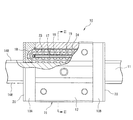
図1〜図9は本発明の第1の実施形態を示す図であり、図1に示すように、第1の実施形態に係る直動案内装置10は、案内レール11、スライダ本体12、エンドキャップ13A,13B及び多数の転動体16を備えている。
案内レール11は鋼等の金属材料を所定の形状に引抜き加工して形成されており、その左右側面部11a,11b(図2参照)には、例えば二条の転動体転動溝14Rが案内レール11の長手方向に沿ってそれぞれ設けられている。
Hereinafter, embodiments of the present invention will be described with reference to the drawings.
1 to 9 are views showing a first embodiment of the present invention. As shown in FIG. 1, a
The
スライダ本体12は鋼等の金属材料からなり、エンドキャップ13A,13Bと共に直動案内装置10のスライダ15を形成している。また、スライダ本体12は案内レール11の両側にブロック状の転動体循環部121(図2参照)を有しており、これら転動体循環部121の内側面には、直線状の転動体転動溝14Sが二条ずつ形成されている。
転動体転動溝14Sは前述した案内レール11の転動体転動溝14Rと対向しており、転動体転動溝14Rと転動体転動溝14Sとの間には、転動体16を案内レール11の長手方向に転走させるための転動体転走路17(図1参照)が形成されている。
The
The rolling element rolling groove 14 S faces the rolling element rolling groove 14 R of the
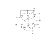
エンドキャップ13A,13Bは、それぞれ複数本の止めネジ(図示せず)によりスライダ本体12の両端に取り付けられている。また、エンドキャップ13A,13Bは樹脂にて成形されたエンドキャップ本体131(図3参照)と、このエンドキャップ本体131と協働して転動体16の方向転換路18(図1参照)を形成する二つのリターンガイド132とからなり、エンドキャップ本体131には、案内レール11とエンドキャップ13A,13Bとの隙間をシールするサイドシール20(図1参照)が取り付けられているとともに、グリースニップル等の潤滑剤供給ニップル(図示せず)をスライダ15に装着するためのニップル取付け孔21が貫設されている。
The
転動体16はスライダ15が案内レール11の長手方向に相対移動すると上記転動体転動溝14R,14S上を転動するようになっており、スライダ15には、直動案内装置10の組立時や分解時に転動体16がスライダ15から脱落するのを防ぐために、二つの転動体保持器22(図2参照)が組み付けられている。また、転動体16は鋼等の金属材料あるいはセラミックス等の材料で球状に形成され、スライダ15内に組み込まれた複数(例えば四つ)の樹脂製セパレータ23(図1及び図2参照)により一定間隔でセパレートされている。
The
方向転換路18は転動体転走路17に連通しており、従って、転動体転走路17を転動した転動体16は例えばエンドキャップ13Aの方向転換路18で方向転換するようになっている。また、方向転換路18はスライダ本体12の転動体循環部121内に形成された転動体戻し路19(図1参照)にも連通しており、従って、転動体戻し路19を転動した転動体16は例えばエンドキャップ13Bの方向転換路18で方向転換するようになっている。
The
転動体戻し路19は転動体転走路17に対応してスライダ本体12の転動体循環部121内に形成されており、各転動体戻し路19には、セパレータ23の摩耗を抑制するために、樹脂製のスリーブ24(図2参照)が挿入されている。
転動体保持器22は、転動体16との摩擦抵抗等を低減するために、例えば樹脂材料を射出成形して形成されている。また、転動体保持器22はスライダ本体12を挟んで相対向する二つのプレート部221(図4参照)を有しており、これらのプレート部221には、エンドキャップ13A,13Bのエンドキャップ本体131及びリターンガイド132に形成された円弧状の突起部25(図3参照)に係合して転動体保持器22を位置決めする位置決め部としての円弧状切欠部26(図5参照)が二つずつ設けられているとともに、グリース等の潤滑剤を方向転換路18や転動体戻し路19に供給する潤滑剤供給溝27が設けられている。
The rolling
The
セパレータ23はベルト状に形成されており、各セパレータ23には、転動体16を収容する複数の孔部231(図6及び図7参照)が一定間隔で穿設されている。
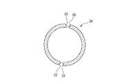
スリーブ24はその両端部がスライダ本体12から突出しており、転動体保持器22のプレート部221には、スライダ本体12から突出するスリーブ24の端部に嵌合すると共にエンドキャップ13A,13Bのリターンガイド132に設けられた円筒状の突起部28(図3参照)に嵌合して方向転換路18と転動体戻し路19とを接続する二つの通路接続孔29(図5参照)が設けられている。また、スリーブ24は転動体戻し路19に沿って二つに分割されており、転動体保持器22には、二つに分割されたスリーブ24の間にセパレータ23の案内路30(図8参照)を形成する案内路形成部として複数の突起部31(図5参照)が設けられている。
The
Both ends of the
潤滑剤供給溝27はエンドキャップ13A,13Bのエンドキャップ本体131に形成された潤滑剤流通溝32(図3参照)に連通しており、この潤滑剤流通溝32には、上記ニップル取付け孔21に装着された潤滑剤供給ニップルからグリース等の潤滑剤が供給されるようになっている。
案内路形成部としての突起部31は転動体保持器22の通路接続孔29に二つずつ設けられており、転動体戻し路19に沿って二つに分割されたスリーブ24には、上記突起部31に係合する断面V字状の溝部33(図9参照)がスリーブ24の軸方向に沿って設けられている。
The
Two
このように構成される直動案内装置10では、スライダ本体12から突出するスリーブ24の端部に嵌合すると共にエンドキャップ13A,13Bのリターンガイド132に設けられた円筒状の突起部28に嵌合して方向転換路18と転動体戻し路19とを接続する通路接続孔29を転動体保持器22のプレート部221に設けたことにより、方向転換路18と転動体戻し路19との接続部に寸法誤差等に起因する段差が発生することを防止することができる。したがって、方向転換路18と転動体戻し路19との接続部に発生した段差に転動体16が衝突することによってスライダ15の振動レベルや騒音レベルが上昇したりすることないので、スライダ15の作動性と騒音特性を高めることができる。
In the
また、前述した従来技術のように、転動体保持器22をエンドキャップ13A,13Bと一体に形成する必要がないので、転動体保持器22の肉厚を最適値に設定できると共に最適な条件で転動体保持器22を樹脂成形することができる。さらに、エンドキャップ13A,13Bのリターンガイド132に形成された突起部25に係合して転動体保持器22を位置決めする位置決め部としての切欠部26を転動体保持器22のプレート部221に設けたことにより、スライダ15を容易かつ高精度に組立てることができる。
Further, unlike the prior art described above, it is not necessary to form the rolling
なお、上述した第1の実施形態では球状に形成された転動体16を用いた場合を例示したが、転動体16は円筒状に形成されていてもよい。また、位置決め部としての切欠部26に係合する突起部25をエンドキャップ本体131とリターンガイド132の双方に設けたが、どちらか一方のみに設けた構成であってもよい。また、突起部25の突出量としては、転動体ピッチの0.5〜1.5倍程度であることが好ましい。
In addition, although the case where the rolling
11 案内レール
12 スライダ本体
13A,13B エンドキャップ
131 エンドキャップ本体
132 リターンガイド
14R,14S 転動体転動溝
15 スライダ
16 転動体
17 転動体転走路
18 方向転換路
19 転動体戻し路
20 サイドシール
21 ニップル取付け孔
22 転動体保持器
221 プレート部
23 セパレータ
24 スリーブ
25 突起部
26 円弧状切欠部(位置決め部)
27 潤滑剤供給溝
28 突起部
29 通路接続孔
30 案内路
31 案内路形成部
32 潤滑剤流通溝
33 溝部
11 the
27
Claims (2)
前記転動体保持器と前記エンドキャップとの連結部を前記スライダ本体と前記エンドキャップとの接合部よりもスライダ側に設けたことを特徴とする直動案内装置。 A guide rail, a slider main body having a rolling element rolling groove facing the rolling element rolling groove formed on the guide rail, and formed between the rolling rail rolling grooves of the guide rail and the slider main body. Along with a relative linear motion of two end caps each having a rolling element rolling path and a direction changing path communicating with a rolling element return path formed in the slider body, and a slider comprising the slider body and the end cap. In the linear motion guide device comprising a number of rolling elements that roll on the rolling elements rolling grooves of the guide rail and the slider body, and a rolling element holder assembled to the slider,
A linear guide apparatus characterized in that a connecting portion between the rolling element holder and the end cap is provided closer to the slider than a joint between the slider body and the end cap.
Priority Applications (1)
| Application Number | Priority Date | Filing Date | Title |
|---|---|---|---|
| JP2005140048A JP2006316889A (en) | 2005-05-12 | 2005-05-12 | Linear guide device |
Applications Claiming Priority (1)
| Application Number | Priority Date | Filing Date | Title |
|---|---|---|---|
| JP2005140048A JP2006316889A (en) | 2005-05-12 | 2005-05-12 | Linear guide device |
Publications (2)
| Publication Number | Publication Date |
|---|---|
| JP2006316889A true JP2006316889A (en) | 2006-11-24 |
| JP2006316889A5 JP2006316889A5 (en) | 2008-01-31 |
Family
ID=37537750
Family Applications (1)
| Application Number | Title | Priority Date | Filing Date |
|---|---|---|---|
| JP2005140048A Pending JP2006316889A (en) | 2005-05-12 | 2005-05-12 | Linear guide device |
Country Status (1)
| Country | Link |
|---|---|
| JP (1) | JP2006316889A (en) |
-
2005
- 2005-05-12 JP JP2005140048A patent/JP2006316889A/en active Pending
Similar Documents
| Publication | Publication Date | Title |
|---|---|---|
| JP4505397B2 (en) | Linear motion guidance unit | |
| US20130216160A1 (en) | Side Seal for Linear Guide Apparatus, and Linear Guide Apparatus | |
| JP5316700B2 (en) | Linear guide device | |
| JP5826537B2 (en) | Linear motion guidance unit | |
| WO2018043045A1 (en) | Linear motion device | |
| JP2006105310A (en) | Linear motion guide unit | |
| JP4025563B2 (en) | Linear motion guide unit with separator between rollers | |
| JP2012067838A (en) | Attachment for temporary shaft of linear guide device | |
| JP5696440B2 (en) | Seal device and linear guide device | |
| JP2006316889A (en) | Linear guide device | |
| JP2007303556A (en) | Linear motion guide device | |
| JP2007032730A (en) | Rolling guide device | |
| JP4551871B2 (en) | Linear motion guide unit with plug on track rail | |
| JP2010169183A (en) | Linear guide device | |
| JP2008133938A (en) | Linear guide | |
| JP4770261B2 (en) | Linear motion guide device | |
| JP4609180B2 (en) | Linear motion guide device | |
| JP2008002660A (en) | Linear guide | |
| JP4640306B2 (en) | Linear motion guide device | |
| JP2008275069A (en) | End cap, and linear guide provided with the end cap | |
| JP4682911B2 (en) | Linear motion guide device | |
| JP4595664B2 (en) | Linear motion guidance device | |
| JP6295624B2 (en) | Side guide for linear guide, linear guide | |
| JP2005201361A (en) | Linear guide device | |
| JP5272350B2 (en) | Linear motion guide device |
Legal Events
| Date | Code | Title | Description |
|---|---|---|---|
| A521 | Written amendment |
Free format text: JAPANESE INTERMEDIATE CODE: A523 Effective date: 20071211 |
|
| A621 | Written request for application examination |
Effective date: 20071211 Free format text: JAPANESE INTERMEDIATE CODE: A621 |
|
| A977 | Report on retrieval |
Free format text: JAPANESE INTERMEDIATE CODE: A971007 Effective date: 20091130 |
|
| A131 | Notification of reasons for refusal |
Free format text: JAPANESE INTERMEDIATE CODE: A131 Effective date: 20100420 |
|
| A02 | Decision of refusal |
Free format text: JAPANESE INTERMEDIATE CODE: A02 Effective date: 20100907 |