JP2006297331A - Production method and apparatus of granulation particle - Google Patents
Production method and apparatus of granulation particle Download PDFInfo
- Publication number
- JP2006297331A JP2006297331A JP2005125798A JP2005125798A JP2006297331A JP 2006297331 A JP2006297331 A JP 2006297331A JP 2005125798 A JP2005125798 A JP 2005125798A JP 2005125798 A JP2005125798 A JP 2005125798A JP 2006297331 A JP2006297331 A JP 2006297331A
- Authority
- JP
- Japan
- Prior art keywords
- combustion
- particles
- furnace
- ash
- waste
- Prior art date
- Legal status (The legal status is an assumption and is not a legal conclusion. Google has not performed a legal analysis and makes no representation as to the accuracy of the status listed.)
- Withdrawn
Links
Images


Classifications
-
- Y—GENERAL TAGGING OF NEW TECHNOLOGICAL DEVELOPMENTS; GENERAL TAGGING OF CROSS-SECTIONAL TECHNOLOGIES SPANNING OVER SEVERAL SECTIONS OF THE IPC; TECHNICAL SUBJECTS COVERED BY FORMER USPC CROSS-REFERENCE ART COLLECTIONS [XRACs] AND DIGESTS
- Y02—TECHNOLOGIES OR APPLICATIONS FOR MITIGATION OR ADAPTATION AGAINST CLIMATE CHANGE
- Y02P—CLIMATE CHANGE MITIGATION TECHNOLOGIES IN THE PRODUCTION OR PROCESSING OF GOODS
- Y02P10/00—Technologies related to metal processing
- Y02P10/25—Process efficiency
Abstract
Description
本発明は、造粒粒子の製造方法および製造装置に関し、詳しくは土砂代替品やコンクリート骨材などに使用できる造粒粒子の製造方法および製造装置に関する。 The present invention relates to a method and apparatus for producing granulated particles, and more particularly to a method and apparatus for producing granulated particles that can be used for earth and sand substitutes, concrete aggregates, and the like.
従来、特許文献1には、汚泥焼却灰から球状粉末スラグを製造するための溶融炉が提案されている。図4には特許文献1に記載の球状粉末スラグ製造処理フローが示されており、同図に基づいて従来の製造法を説明すると、50は下水汚泥焼却設備から排出された下水汚泥焼却灰を貯留するホッパ、51は定量フィーダであり、ホッパ50内の焼却灰は定量フィーダ51で切出されたのち図示しないブロワにより、球状粉末スラグ製造用溶融炉53に配管52を介して輸送される。
Conventionally, Patent Document 1 proposes a melting furnace for producing spherical powder slag from sludge incineration ash. FIG. 4 shows a spherical powder slag manufacturing process flow described in Patent Document 1. The conventional manufacturing method will be described with reference to FIG. 4.
溶融炉53は、図5に示すように、炉内断面積が下方に行くにつれて段階的に大きくなっており、炉内壁の各段差部54には冷却空気供給手段としてのノズル55が円周方向に数10個ずつ取り付けられており、冷却空気を下方に噴出して、炉壁の温度を下げることにより炉壁へのクリンカの付着を防止している。
As shown in FIG. 5, the
溶融炉53の頂部にはバーナ56が取り付けられ、バーナ56は焼却灰供給管、燃料供給路、燃焼用気体供給路を備えた3重管構造を成している。燃料供給路および燃焼用気体供給路から供給される燃料と燃焼用気体とにより形成される高温の燃焼火炎S中に、焼却灰供給管から前記焼却灰が燃焼用気体(空気)の一部とともに供給され、前記燃焼火炎S中で加熱され、焼却灰は浮遊状態で溶融して球状化する。この球状化溶融粒子はやがて前記燃焼火炎Sの外へ搬出され、ノズル55からの冷却空気で溶融温度以下に保持された炉内で急冷されることにより凝固して球状粉末スラグとなる。
A
前記球状粉末スラグのうち粒径の大きな球状粉末スラグは炉底部に落下し、排出口57から取り出され、一方、粒径の小さな球状粉末スラグは排ガス排出口58から排ガスとともに熱交換器59を通って電気集塵機60に至り、排ガスから分離される。これにより、球状粉末スラグを炉床に設けた球状粉末スラグ排出口57および電気集塵機60から得る。
Of the spherical powder slag, the spherical powder slag having a large particle size falls to the bottom of the furnace and is taken out from the
上記の技術で使用されている溶融炉は、火炎中で粉体を溶融して球状化するものであり、フレーム溶融炉と称されており、非特許文献1にも同様のフレーム溶融炉が開示されている。
近年、エネルギー発電の推進において、廃棄物発電分野の核となる廃棄物燃焼からの高効率発電を可能とする循環流動層ボイラが注目されている。 In recent years, in the promotion of energy power generation, circulating fluidized bed boilers that enable high-efficiency power generation from waste combustion, which is the core of the waste power generation field, have attracted attention.
従来の技術の問題点において、かかる循環流動層ボイラにおいて、フレーム溶融方式では、主燃料はオイルであり、固形廃棄物を燃料に出来ない。そのため、運転コストが高くなり、CO2排出削減に寄与することが出来ないという欠点がある。 In the problem of the prior art, in such a circulating fluidized bed boiler, in the flame melting method, the main fuel is oil and solid waste cannot be used as fuel. Therefore, there is a drawback that the operating cost is high and cannot contribute to CO 2 emission reduction.
プラズマ溶融方式や誘導加熱方式などの方式では、大量の電力を消費するため、運転コストが高く経済的な方式ではない。 Methods such as the plasma melting method and the induction heating method consume a large amount of electric power, and thus are not economical because of high operating costs.
従来、下水汚泥燃焼灰から人工軽量骨材を製造するために、灰焼成用ロータリーキルンが用いられているが、燃料は全て化石燃料である。 Conventionally, rotary kilns for ash firing have been used to produce artificial lightweight aggregates from sewage sludge combustion ash, but all fuel is fossil fuel.
本発明者は、灰焼成用ロータリーキルンの燃料として、廃棄物を利用する技術の開発を試み、以下のような課題があることがわかった。 The present inventor has attempted to develop a technology that uses waste as a fuel for a rotary kiln for ash firing, and has found the following problems.
すなわち、従来の灰焼成用ロータリーキルンによる焼成方法において、廃棄物燃料を用いる廃棄物燃焼灰は10〜40ミクロンの細かいフライアッシュとなって、灰焼成用ロータリーキルンによる燃焼ガスに同伴され、短時間で灰焼成用ロータリーキルンを通過する。このため廃棄物燃焼灰は十分に焼成されない。有害重金属を含む廃棄物燃焼灰が十分焼成されないと、有害重金属は廃棄物燃焼灰に含まれた状態となるので、その燃焼灰を排出後捕集した後に、薬品などを添加して無害化する必要があり、処理コストが高くなるという問題があった。 That is, in the conventional calcination method using an ash firing rotary kiln, the waste combustion ash using waste fuel becomes fine fly ash of 10 to 40 microns and is accompanied by the combustion gas produced by the ash firing rotary kiln. Pass through a rotary kiln for firing. For this reason, waste combustion ash is not fully baked. If the waste combustion ash containing toxic heavy metals is not burned sufficiently, the toxic heavy metals will be contained in the waste combustion ash. After the combustion ash is discharged and collected, it is rendered harmless by adding chemicals. There is a problem that the processing cost becomes high.
また、灰焼成用ロータリーキルンで造粒する造粒粒子に廃棄物燃焼灰が付着し、造粒品自体の有害重金属濃度が上昇するため、製品の品質が確保できないという問題があった。 Further, there is a problem that the quality of the product cannot be ensured because the waste combustion ash adheres to the granulated particles granulated by the rotary kiln for ash firing, and the concentration of harmful heavy metals in the granulated product itself increases.
そこで、本発明は、廃棄物燃料に含まれる有害重金属を球状固化粒子中に封じ込めて無害化することが可能な造粒粒子の製造方法及び製造装置を提供することを課題とする。 Then, this invention makes it a subject to provide the manufacturing method and manufacturing apparatus of the granulated particle which can contain the harmful heavy metal contained in waste fuel in a spherical solidification particle, and can make it harmless.
また本発明の他の課題は、以下の記載によって明らかとなる。 Other problems of the present invention will become apparent from the following description.
本発明の上記課題は、以下の各発明によって解決される。 The above-described problems of the present invention are solved by the following inventions.
(請求項1)
フライアッシュを灰造粒機により所定範囲の粒径の粒子に造粒する造粒工程と、
前記造粒工程で造粒された造粒粒子及び有害重金属を含む廃棄物燃料をキルン焼成炉に導入して1050〜1200℃の焼成温度によって焼成する焼成工程と、
前記焼成工程から排出される燃焼排ガス、造粒粒子及び廃棄物燃焼灰を下流の後燃焼炉に導入し、該後燃焼炉の前段で1300〜1500℃の温度で前記造粒粒子の表面に付着した廃棄物燃焼灰を溶融し、前記後燃焼炉の後段で冷却用空気を導入して、前記表面に前記廃棄物燃焼灰が溶融状態で存在する造粒粒子を含む造粒粒子を冷却して実質的に球状形状の固化物を生成する後燃焼工程とを有することを特徴とする造粒粒子の製造方法。
(Claim 1)
A granulation step of granulating fly ash into particles having a predetermined range of particle sizes by an ash granulator;
A firing step of introducing waste fuel containing granulated particles and harmful heavy metals granulated in the granulation step into a kiln firing furnace and firing at a firing temperature of 1050 to 1200 ° C;
Combustion exhaust gas, granulated particles and waste combustion ash discharged from the firing step are introduced into a downstream post-combustion furnace, and adhere to the surface of the granulated particles at a temperature of 1300 to 1500 ° C. at the front stage of the post-combustion furnace. The waste combustion ash is melted, cooling air is introduced at a later stage of the post-combustion furnace, and the granulated particles including the granulated particles in which the waste combustion ash exists in a molten state are cooled on the surface. And a post-combustion step for producing a substantially spherical solidified product.
(請求項2)
前記造粒工程が、バイオマス、各種産業廃棄物及び化石燃料から選ばれる燃料を燃焼した燃焼熱により高温高圧の蒸気を発生する循環流動層ボイラにおける燃焼後に捕集される10〜50ミクロンのフライアッシュと水とセメントからなる原料を攪拌・混練して、所定サイズの粒子に造粒することを特徴とする請求項1記載の造粒粒子の製造方法。
(Claim 2)
10 to 50 micron fly ash collected after combustion in a circulating fluidized bed boiler in which the granulation step generates high-temperature and high-pressure steam by combustion heat obtained by burning fuel selected from biomass, various industrial wastes and
(請求項3)
前記焼成工程で使用される前記有害重金属を含む廃棄物燃料が、廃棄プラスチック、PRF及び建築廃材などの廃棄物であることを特徴とする請求項1又は2記載の造粒粒子の製造方法。
(Claim 3)
The method for producing granulated particles according to claim 1 or 2, wherein the waste fuel containing the toxic heavy metal used in the firing step is waste such as waste plastic, PRF, and building waste.
(請求項4)
前記焼成工程は、前記造粒工程で造粒された造粒物を1050〜1200℃の焼成温度で0.5〜2時間保持して焼成することを特徴とする請求項1、2又は3記載の造粒粒子の製造方法。
(Claim 4)
The said baking process hold | maintains the granulated material granulated by the said granulation process at the baking temperature of 1050-1200 degreeC for 0.5 to 2 hours, and baked. A method for producing granulated particles.
(請求項5)
キルン焼成炉出口での燃焼空気比を、1.0以上とすることを特徴とする請求項1〜4の何れかに記載の造粒粒子の製造方法。
(Claim 5)
The method for producing granulated particles according to any one of claims 1 to 4, wherein a combustion air ratio at the exit of the kiln firing furnace is 1.0 or more.
(請求項6)
後燃焼炉の入り口で化石燃料を吹き込んだ後の理論空気比を0.9〜1.1に保持することを特徴とする請求項1〜5の何れかに記載の造粒粒子の製造方法。
(Claim 6)
The method for producing granulated particles according to any one of claims 1 to 5, wherein the theoretical air ratio after fossil fuel is blown at the entrance of the post-combustion furnace is maintained at 0.9 to 1.1.
(請求項7)
フライアッシュを所定範囲の粒径の粒子に造粒する造粒機と、
前記造粒機で造粒された造粒粒子及び有害重金属を含む廃棄物を導入して1050〜1200℃の焼成温度によって焼成するキルン焼成炉と、
前記キルン焼成炉の下流に配置され、該キルン焼成炉から排出される燃焼排ガス、造粒粒子及び廃棄物燃焼灰を導入し、前段で1300〜1500℃の温度で前記造粒粒子の表面に付着した廃棄物燃焼灰を溶融し、後段で冷却用空気を導入して、表面に前記廃棄物燃焼灰が溶融状態で存在する造粒粒子を含む造粒粒子を冷却して実質的に球状形状の固化物を生成する後燃焼炉とを有することを特徴とする造粒粒子の製造装置。
(Claim 7)
A granulator for granulating fly ash into particles having a predetermined particle size;
A kiln firing furnace for introducing waste containing granulated particles and harmful heavy metals granulated by the granulator and firing at a firing temperature of 1050 to 1200 ° C .;
The combustion exhaust gas, granulated particles, and waste combustion ash, which are disposed downstream of the kiln calcining furnace and discharged from the kiln calcining furnace, are introduced and adhered to the surface of the granulated particles at a temperature of 1300 to 1500 ° C. in the previous stage. The waste combustion ash is melted, cooling air is introduced at a later stage, and the granulated particles including the granulated particles in which the waste combustion ash exists in a molten state are cooled on the surface to form a substantially spherical shape. An apparatus for producing granulated particles, comprising a post-combustion furnace for producing a solidified product.
(請求項8)
後燃焼炉が、フレーム溶融炉であることを特徴とする請求項7記載の造粒粒子の製造装置。
(Claim 8)
The apparatus for producing granulated particles according to claim 7, wherein the post-combustion furnace is a flame melting furnace.
請求項1記載の発明によれば、廃棄物燃料に含まれる有害重金属を球状固化粒子中に封じ込めて無害化することが可能となる。また得られた造粒粒子は、循環流動層ボイラの珪砂代替品、土壌改良材などの土砂代替品及びコンクリート骨材として使用することが可能である。製造された造粒焼成品内に含まれる有害重金属の溶出量は、土壌環境基準値内を満たしており、バグフィルターによる捕集灰の有害重金属の溶出に対しても土壌環境基準値も満たしている。 According to the first aspect of the present invention, it is possible to contain harmful heavy metals contained in the waste fuel in the spherical solidified particles and render them harmless. Further, the obtained granulated particles can be used as a silica sand substitute for a circulating fluidized bed boiler, a soil substitute such as a soil improvement material, and a concrete aggregate. The amount of toxic heavy metal elution contained in the manufactured granulated baked product satisfies the soil environment standard value, and the soil environment standard value is also satisfied for the elution of toxic heavy metal in the collected ash by the bag filter. Yes.
請求項2記載の発明によれば、循環流動層ボイラから発生するフライアッシュを有効利用できる。
According to invention of
請求項3記載の発明によれば、燃料単価が化石燃料に比べ1/5〜1/10に低減できる。 According to invention of Claim 3, a fuel unit price can be reduced to 1/5-1/10 compared with a fossil fuel.
請求項4記載の発明によれば、有害重金属を粒子内に封じ込めて無害化するとともに、強固な固化物を生成することができる。 According to the fourth aspect of the present invention, it is possible to contain harmful heavy metals in the particles to render them harmless and to produce a solidified product.
請求項5記載の発明によれば、キルン焼成炉で廃棄物燃料の完全燃焼を図ることができる。 According to the fifth aspect of the present invention, the complete combustion of the waste fuel can be achieved in the kiln firing furnace.
請求項6記載の発明によれば、後燃焼炉での火炎温度の上昇を図ることができる。 According to the sixth aspect of the present invention, it is possible to increase the flame temperature in the post-combustion furnace.
請求項7、8記載の発明によれば、廃棄物燃料に含まれる有害重金属を球状固化粒子中に封じ込めて無害化することが可能となる。また得られた造粒粒子は、循環流動層ボイラの珪砂代替品、土壌改良材などの土砂代替品及びコンクリート骨材として使用することが可能である。製造された造粒焼成品内に含まれる有害重金属の溶出量は、土壌環境基準値内を満たしており、バグフィルターによる捕集灰の有害重金属の溶出に対しても土壌環境基準値も満たしている。 According to the seventh and eighth aspects of the invention, it is possible to make the harmful heavy metal contained in the waste fuel contained in the spherical solidified particles harmless. Further, the obtained granulated particles can be used as a silica sand substitute for a circulating fluidized bed boiler, a soil substitute such as a soil improvement material, and a concrete aggregate. The amount of toxic heavy metal elution contained in the manufactured granulated baked product satisfies the soil environment standard value, and the soil environment standard value is also satisfied for the elution of toxic heavy metal in the collected ash by the bag filter. Yes.
以下、本発明の実施の形態を図面に基づいて説明する。 Hereinafter, embodiments of the present invention will be described with reference to the drawings.
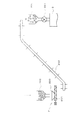
図1は本発明の造粒粒子の製造方法を実施する装置の好ましい態様を示すフロー図であり、同図において、1は灰造粒機であり、たとえば混合攪拌造粒機、パン型造粒機などを使用できる。 FIG. 1 is a flowchart showing a preferred embodiment of an apparatus for carrying out the method for producing granulated particles of the present invention. In the figure, 1 is an ash granulator, for example, a mixed stirring granulator, a bread granulator You can use the machine.
本実施の形態では、造粒タンク100と攪拌機101を備えた攪拌造粒機を採用した例について説明する。
This Embodiment demonstrates the example which employ | adopted the stirring granulator provided with the
造粒タンク100に飛灰(フライアッシュ)を導入し、フライアッシュに対して水10%程度添加した後、攪拌機101を作動させ、攪拌造粒して所定範囲の粒径の造粒粒子を得る。なお必要によりバインダーを使用することもできる。攪拌機101の回転数は、60〜120rpm程度が所定範囲の粒径の造粒粒子を得る上で好ましい。
After introducing fly ash (fly ash) into the
造粒タンク100に導入されるフライアッシュとしては、特に限定されないが、例えば図示しない循環流動層ボイラから排出される燃焼灰(バグ灰)などが挙げられ、フライアッシュの粒径は通常10〜50ミクロン(平均20〜40ミクロン)の範囲である。循環流動層ボイラは、バイオマス、各種産業廃棄物及び化石燃料から選ばれる燃料を燃焼した燃焼熱により高温高圧の蒸気を発生する。
Although it does not specifically limit as fly ash introduced into the
得られた造粒粒子の粒径は、本発明により得られる製品が土砂代替品ならば100〜500ミクロン、コンクリート骨材(砂や小石など)ならば5〜20mmのように、製品目的により変化させることが好ましい。 The particle size of the resulting granulated particles varies depending on the purpose of the product, such as 100 to 500 microns if the product obtained by the present invention is an earth and sand substitute, and 5 to 20 mm if the concrete aggregate (sand, pebbles, etc.). It is preferable to make it.
造粒後に12〜48時間程度、建て屋内等で自然養生させることが好ましい。 It is preferable to allow natural curing in a building or the like for about 12 to 48 hours after granulation.
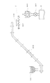
攪拌造粒機1で造粒された粒子は、切出し部2を介してキルン焼成炉3に搬送されるが、かかる搬送系について図2および図3に基づいて説明する。
The particles granulated by the agitation granulator 1 are conveyed to the kiln firing furnace 3 through the
攪拌造粒機1で造粒された粒子は、図2で示すように、ホッパー102に受け入れ、切出し部2の投入部200を介してスクリューフィーダ201で所定量ずつ切出す。切出された造粒粒子は、コンベア202によってキルン焼成炉3の入り口に設けられた投入部300に投入され、シール用ロータリーバルブ301の開閉により、キルン焼成炉3に導入される。
As shown in FIG. 2, the particles granulated by the stirring granulator 1 are received by the
搬送系の態様は、図3に示す態様であってもよい。すなわち、切出し部2をキルン焼成炉3の入り口近傍に配置し、攪拌造粒機1で造粒された粒子をホッパー102で受け入れ、該ホッパー102から供給される粒子をコンベア202により切出し部2の投入部200を介してスクリューフィーダ201で所定量ずつ切出す。切出された造粒粒子は、キルン焼成炉3の入り口に設けられた投入部300に投入され、シール用ロータリーバルブ301の開閉により、キルン焼成炉3に導入される。
The mode of the transport system may be the mode shown in FIG. That is, the cut-out
キルン焼成炉3としては、例えば起動用バーナーを有する内燃並流式焼成用ロータリーキルンを使用できる。 As the kiln firing furnace 3, for example, an internal combustion co-current firing rotary kiln having an activation burner can be used.
キルン焼成炉3の燃料としては有害重金属を含む廃棄物燃料が使用される。廃棄物燃料は、廃棄物燃料切出し部4から所定量ずつ切出される。廃棄物燃料切出し部4は、投入部400とスクリューフィーダ401を備えている。
As fuel for the kiln firing furnace 3, waste fuel containing toxic heavy metals is used. The waste fuel is cut out from the waste fuel cutout unit 4 by a predetermined amount. The waste fuel cutting unit 4 includes a
廃棄物燃料としては、廃棄プラスチック、RPF(Refuse Paper&Plastic Fuel)、RDF(廃棄物固形化燃料)、建築廃材などの廃棄物燃料が挙げられる。かかる廃棄物燃料を使用することにより、燃料単価が化石燃料に比べ、1/5〜1/10に低減できる。 Examples of the waste fuel include waste plastics, RPF (Refuse Paper & Plastic Fuel), RDF (Waste Solidified Fuel), and building waste materials. By using such waste fuel, the unit price of fuel can be reduced to 1/5 to 1/10 compared to fossil fuel.
キルン焼成炉3では、有害重金属を含む廃棄物燃料を用いて、前記造粒粒子を1050〜1200℃の焼成温度で0.5〜2時間保持して焼成することが有害重金属を粒子内に封じ込める上で好ましい。 In the kiln firing furnace 3, firing the granulated particles by holding the granulated particles at a firing temperature of 1050 to 1200 ° C. for 0.5 to 2 hours using waste fuel containing harmful heavy metals encloses the harmful heavy metals in the particles. Preferred above.
焼成温度が1050〜1200℃の温度で0.5時間未満の保持では、有害重金属を粒子内に封じ込めることができず、また焼成むらが生じ、2時間を越えても効果の更なる上昇は見込めない。 If the firing temperature is maintained at 1050 to 1200 ° C. for less than 0.5 hours, harmful heavy metals cannot be contained in the particles, and firing unevenness will occur, and further increase in the effect can be expected even if the firing temperature exceeds 2 hours. Absent.
キルン焼成炉3内で造粒粒子と空気の流れ方向は、本発明の効果を良好に奏する上では並流方式が好ましい。 The flow direction of the granulated particles and air in the kiln firing furnace 3 is preferably a co-current system in order to achieve the effects of the present invention.
キルン焼成炉3の出口での燃焼空気比は、1.0以上とすることが完全燃焼を実現するために好ましく、より好ましくは1.3〜1.5の範囲である。 The combustion air ratio at the outlet of the kiln firing furnace 3 is preferably 1.0 or more in order to achieve complete combustion, and more preferably in the range of 1.3 to 1.5.
次に、図1において、5は後燃焼炉である。後燃焼炉5には、前記キルン焼成炉3から排出される燃焼排ガス、造粒粒子及び10〜40ミクロンの廃棄物燃焼灰を導入する。この導入の際に、廃棄物燃焼灰の一部は造粒粒子の表面に付着している。 Next, in FIG. 1, 5 is a post-combustion furnace. In the post-combustion furnace 5, combustion exhaust gas, granulated particles and 10-40 micron waste combustion ash discharged from the kiln firing furnace 3 are introduced. During this introduction, a part of the waste combustion ash adheres to the surface of the granulated particles.
後燃焼炉5の形状は特に限定されるわけではないが、本実施の形態では円筒型フレーム溶融炉を好ましく採用している。 The shape of the post-combustion furnace 5 is not particularly limited, but a cylindrical frame melting furnace is preferably employed in the present embodiment.
後燃焼炉5の入口部500には、キルン焼成炉3から燃焼排ガス、造粒粒子及び10〜40ミクロンの廃棄物燃焼灰が導入され、プロパンガス、都市ガス、オイルなどの化石燃料が供給され、燃焼を起こさせる。
Combustion exhaust gas, granulated particles, and 10-40 micron waste combustion ash are introduced from the kiln calcining furnace 3 to the
後燃焼炉5の入口部500は、外側外周上からプロパンや都市ガスなどの燃料が内側に向けて吹き込まれるシンプルな構造となっており、入口部500先端から1300〜1500℃の火炎が形成される。この火炎中で10〜40ミクロンの廃棄物燃焼灰は、溶融、球状化される。
The
また前記火炎が形成され、1300〜1500℃の温度で前記造粒粒子の表面に付着した廃棄物燃焼灰を溶融する。 Further, the flame is formed, and the waste combustion ash adhering to the surface of the granulated particles is melted at a temperature of 1300 to 1500 ° C.
火炎を出た後の後燃焼炉5の後段では、冷却空気と混合され、溶融炉出口で800℃程度まで冷却固化される。 In the latter stage of the post-combustion furnace 5 after exiting the flame, it is mixed with cooling air and cooled and solidified to about 800 ° C. at the outlet of the melting furnace.
フレーム溶融炉5の後段は、図示しないが、多段分割されており、各段毎にファン501から配管502を介して冷却空気が導入される構造になっている。またフレーム溶融炉5底部にも配管504を介して空気が導入される空気導入部503が形成されている。505は球状粒子排出部である。排出された球状粒子は、粒子冷却部6に送られる。
Although not shown, the subsequent stage of the frame melting furnace 5 is divided into multiple stages, and cooling air is introduced from the
粒子冷却部6は、たとえば回転ドラム型を採用でき、直接冷却または間接冷却のいずれでもよい。粒子冷却部6には冷却用の空気配管600が接続されている。
The particle cooling unit 6 can adopt, for example, a rotary drum type, and may be either direct cooling or indirect cooling. A cooling
粒子冷却部6の内部は、空気(温度150℃程度)がB方向、粒子(入口で800℃程度)がA方向に移動し、互いに向流になるように構成されることが冷却効果を上昇させる上で好ましい。 The inside of the particle cooling unit 6 is configured such that air (temperature about 150 ° C.) moves in the B direction and particles (about 800 ° C. at the inlet) move in the A direction, so that the cooling effect increases. This is preferable.
粒子冷却部6で冷却された球状粒子は、50〜150℃程度まで冷却され、製品7として外部に排出され、貯留される。 The spherical particles cooled by the particle cooling unit 6 are cooled to about 50 to 150 ° C., discharged to the outside as a product 7 and stored.
粒子冷却部6で冷却に寄与して温度上昇した空気は、前記キルン焼成炉3に送られ、燃焼空気として使用できる。この際、温度が上昇しているので、起動用オイルの使用量が少なくて済む効果がある。 The air whose temperature has increased by contributing to cooling in the particle cooling section 6 is sent to the kiln firing furnace 3 and can be used as combustion air. At this time, since the temperature rises, there is an effect that the amount of starting oil used can be reduced.
本発明の好ましい態様では、後燃焼炉5で化石燃料を使用しているが、キルン焼成炉3で1050〜1200℃の温度に昇温しているので、300℃程度の温度上昇に相当する熱量分だけでよく、経済性に優れる効果がある。 In the preferred embodiment of the present invention, fossil fuel is used in the post-combustion furnace 5, but since the temperature is raised to 1050 to 1200 ° C. in the kiln firing furnace 3, the amount of heat corresponding to a temperature increase of about 300 ° C. Only minutes are enough, and it has the effect of being economical.
キルン焼成炉3に引き続いて、後燃焼炉で、好ましくは0.2〜0.4秒の短時間、高温火炎内を通過させることにより、造粒粒子の表面部分の一部溶融を行った後冷却するため、焼成むらを解消できるばかりでなく、球状固化物の強度増大を図ることができる。 After the kiln calcining furnace 3 is partially melted in the surface portion of the granulated particles by passing through a high-temperature flame for a short time of 0.2 to 0.4 seconds, preferably in a post-combustion furnace. Because of cooling, not only firing unevenness can be eliminated, but also the strength of the spherical solidified product can be increased.
また、本発明の好ましい態様によれば、キルン焼成炉3では、有害重金属を含む廃棄物燃料を用いて、前記造粒粒子を1050〜1200℃の焼成温度で0.5〜2時間保持して焼成することにより有害重金属を粒子内に封じ込める。さらに粒子表面に付着した廃棄物燃焼灰も後燃焼炉で溶融されるため、冷却固化された球状粒子中に有害重金属を封じ込めて、無害化できる。 Moreover, according to the preferable aspect of this invention, in the kiln baking furnace 3, the said granulated particle is hold | maintained at the calcination temperature of 1050-1200 degreeC for 0.5 to 2 hours using the waste fuel containing a toxic heavy metal. By calcination, harmful heavy metals are contained in the particles. Further, since the waste combustion ash adhering to the particle surface is also melted in the post-combustion furnace, harmful heavy metals can be contained in the cooled and solidified spherical particles to make them harmless.
さらに、本発明の好ましい態様によれば、キルン焼成炉3での燃焼空気比は、1.0以上として廃棄物燃料の完全燃焼が図られ、その後、後燃焼炉5の入口部でプロパンなどを吹き込み、火炎の温度をアップするため、燃焼空気比は0.9〜1.1程度に保持される。その下流で段階的に冷却用空気を導入して排ガスを800〜1000℃程度まで冷却するので、空気比も1.3以上で完全燃焼が図られる。 Furthermore, according to a preferred aspect of the present invention, the combustion air ratio in the kiln calcining furnace 3 is set to 1.0 or more so that the waste fuel is completely burned, and then propane or the like is introduced at the inlet of the post-combustion furnace 5. In order to increase the temperature of blowing and flame, the combustion air ratio is maintained at about 0.9 to 1.1. Downstream, cooling air is introduced stepwise to cool the exhaust gas to about 800 to 1000 ° C., so that complete combustion can be achieved with an air ratio of 1.3 or more.
なお、本発明では、得られた球状固化物は、完全に球状であることまで要求されず、実質的に球状であればよい。実質的にというのは、直交する直径の比が±10%以内の変動を許容する意味である。 In the present invention, the obtained spherical solidified product is not required to be completely spherical, and may be substantially spherical. Substantially means that the variation in the ratio of orthogonal diameters is within ± 10%.
吸引ファン10によって吸引された約800℃程度の廃棄物燃焼灰および燃焼排ガスは、たとえば半乾式タイプの反応冷却塔8において、消石灰または炭酸ナトリウムなどのアルカリスプレーを使用し、排ガス温度を150〜200℃に冷却し、排ガス中の腐食成分であるHClやSO2を除去する。
The waste combustion ash and the combustion exhaust gas of about 800 ° C. sucked by the
反応冷却塔8で処理された廃棄物燃焼灰および燃焼排ガスは、バグフィルター9を通過させ、廃棄物燃焼灰を捕集する。捕集した燃焼灰は有効利用したりまたは埋め立て処理される。また、燃焼排ガスは外部に放出される。
Waste combustion ash and combustion exhaust gas treated in the
以下に、本発明の実施例を説明するが、本発明はかかる実施例によって限定されない。 Examples of the present invention will be described below, but the present invention is not limited to such examples.
実施例1
本発明により製造した造粒焼成品の有害重金属の溶出試験を環境庁告示46号の方法に従って分析し、土壌環境基準との比較を行った。
Example 1
The elution test for harmful heavy metals of the granulated and fired product produced according to the present invention was analyzed according to the method of Environment Agency Notification No. 46 and compared with the soil environmental standards.
造粒焼成品の有害重金属の溶出試験結果を表1に示す。 Table 1 shows the results of the toxic heavy metal dissolution test of the granulated and fired product.

表1より、造粒焼成品の有害重金属の溶出値は、土壌環境基準値を満たしていることがわかる。 From Table 1, it can be seen that the elution value of harmful heavy metals in the granulated and fired product satisfies the soil environmental standard value.
実施例2
本発明により製造した造粒品の物性を計測し、その結果を表2に示す。
Example 2
The physical properties of the granulated product produced according to the present invention were measured, and the results are shown in Table 2.
圧壊強度:粒子1個を圧縮試験機上にのせ、物質に荷重をかけ破壊強度を調べる。 Crushing strength: A particle is placed on a compression tester, a load is applied to the substance, and the breaking strength is examined.
表2より、造粒粒子は上記のような物性を示すので、循環流動層ボイラの珪砂代替粒子として使用可能であり、また、埋め立てだけでなく、土砂代替品、砂利代替品及び土壌代替品などとしても有効利用できることがわかる。 From Table 2, since the granulated particles exhibit the physical properties as described above, they can be used as silica sand substitute particles for circulating fluidized bed boilers, as well as landfill substitutes, gravel substitutes, soil substitutes, etc. It can be seen that it can be used effectively.
実施例3
バグフィルター捕集灰の有害重金属溶出試験を環境庁告示46号の方法に従って行い、土壌環境基準値との比較を行った。
Example 3
Hazardous heavy metal elution test of bag filter ash was conducted according to the method of Environment Agency Notification No. 46 and compared with the soil environment standard value.
その結果を表3に示す。 The results are shown in Table 3.
表3より、バグフィルター捕集灰の有害重金属溶出値は土壌環境基準を満たしていることがわかる。 From Table 3, it can be seen that the toxic heavy metal elution value of the bag filter ash meets the soil environmental standards.
1:灰造粒機、攪拌造粒機
100:造粒タンク
101:攪拌機
102:ホッパー
2:切出し部
200:投入部
201:スクリューフィーダ
202:コンベア
3:キルン焼成炉
300:投入部
301:ロータリーバルブ
4:廃棄物燃料切出し部
400:投入部
401:スクリューフィーダ
5:後燃焼炉
500:入口部
501:ファン
502:配管
503:空気導入部
504:配管
505:球状粒子排出部
6:粒子冷却部
600:空気配管
7:製品
8:反応冷却塔
9:バグフィルター
10:吸引ファン
DESCRIPTION OF SYMBOLS 1: Ash granulator, stirring granulator 100: Granulation tank 101: Stirrer 102: Hopper 2: Cutting-out part 200: Input part 201: Screw feeder 202: Conveyor 3: Kiln baking furnace 300: Input part 301: Rotary valve 4: Waste fuel cutting section 400: Input section 401: Screw feeder 5: Post-combustion furnace 500: Inlet section 501: Fan 502: Piping 503: Air introduction section 504: Piping 505: Spherical particle discharge section 6: Particle cooling section 600 : Air piping 7: Product 8: Reaction cooling tower 9: Bag filter 10: Suction fan
Claims (8)
前記造粒工程で造粒された造粒粒子及び有害重金属を含む廃棄物燃料をキルン焼成炉に導入して1050〜1200℃の焼成温度によって焼成する焼成工程と、
前記焼成工程から排出される燃焼排ガス、造粒粒子及び廃棄物燃焼灰を下流の後燃焼炉に導入し、該後燃焼炉の前段で1300〜1500℃の温度で前記造粒粒子の表面に付着した廃棄物燃焼灰を溶融し、前記後燃焼炉の後段で冷却用空気を導入して、前記表面に前記廃棄物燃焼灰が溶融状態で存在する造粒粒子を含む造粒粒子を冷却して実質的に球状形状の固化物を生成する後燃焼工程とを有することを特徴とする造粒粒子の製造方法。 A granulation step of granulating fly ash into particles having a predetermined range of particle sizes by an ash granulator;
A firing step of introducing waste fuel containing granulated particles and harmful heavy metals granulated in the granulation step into a kiln firing furnace and firing at a firing temperature of 1050 to 1200 ° C;
Combustion exhaust gas, granulated particles and waste combustion ash discharged from the firing step are introduced into a downstream post-combustion furnace, and adhere to the surface of the granulated particles at a temperature of 1300 to 1500 ° C. at the front stage of the post-combustion furnace. The waste combustion ash is melted, cooling air is introduced at a later stage of the post-combustion furnace, and the granulated particles including the granulated particles in which the waste combustion ash exists in a molten state are cooled on the surface. And a post-combustion step for producing a substantially spherical solidified product.
前記造粒機で造粒された造粒粒子及び有害重金属を含む廃棄物を導入して1050〜1200℃の焼成温度によって焼成するキルン焼成炉と、
前記キルン焼成炉の下流に配置され、該キルン焼成炉から排出される燃焼排ガス、造粒粒子及び廃棄物燃焼灰を導入し、前段で1300〜1500℃の温度で前記造粒粒子の表面に付着した廃棄物燃焼灰を溶融し、後段で冷却用空気を導入して、表面に前記廃棄物燃焼灰が溶融状態で存在する造粒粒子を含む造粒粒子を冷却して実質的に球状形状の固化物を生成する後燃焼炉とを有することを特徴とする造粒粒子の製造装置。 A granulator for granulating fly ash into particles having a predetermined particle size;
A kiln firing furnace for introducing waste containing granulated particles and harmful heavy metals granulated by the granulator and firing at a firing temperature of 1050 to 1200 ° C .;
The combustion exhaust gas, granulated particles, and waste combustion ash, which are disposed downstream of the kiln calcining furnace and discharged from the kiln calcining furnace, are introduced and adhered to the surface of the granulated particles at a temperature of 1300 to 1500 ° C. in the previous stage. The waste combustion ash is melted, cooling air is introduced at a later stage, and the granulated particles including the granulated particles in which the waste combustion ash exists in a molten state are cooled on the surface to form a substantially spherical shape. An apparatus for producing granulated particles, comprising a post-combustion furnace for producing a solidified product.
The apparatus for producing granulated particles according to claim 7, wherein the post-combustion furnace is a flame melting furnace.
Priority Applications (1)
| Application Number | Priority Date | Filing Date | Title |
|---|---|---|---|
| JP2005125798A JP2006297331A (en) | 2005-04-22 | 2005-04-22 | Production method and apparatus of granulation particle |
Applications Claiming Priority (1)
| Application Number | Priority Date | Filing Date | Title |
|---|---|---|---|
| JP2005125798A JP2006297331A (en) | 2005-04-22 | 2005-04-22 | Production method and apparatus of granulation particle |
Publications (1)
| Publication Number | Publication Date |
|---|---|
| JP2006297331A true JP2006297331A (en) | 2006-11-02 |
Family
ID=37466056
Family Applications (1)
| Application Number | Title | Priority Date | Filing Date |
|---|---|---|---|
| JP2005125798A Withdrawn JP2006297331A (en) | 2005-04-22 | 2005-04-22 | Production method and apparatus of granulation particle |
Country Status (1)
| Country | Link |
|---|---|
| JP (1) | JP2006297331A (en) |
Cited By (3)
| Publication number | Priority date | Publication date | Assignee | Title |
|---|---|---|---|---|
| CN102183026A (en) * | 2011-02-23 | 2011-09-14 | 广东工业大学 | Device and method for removing heavy metal Pb from fly ash generated in sludge incineration |
| JP2016186369A (en) * | 2015-03-27 | 2016-10-27 | クリアーシステム株式会社 | Slag manufacturing device and slag manufacturing method |
| CN109776064A (en) * | 2019-01-17 | 2019-05-21 | 惠州务本材料科技有限公司 | A kind of method of dry process Water Storage Pottery Clay |
-
2005
- 2005-04-22 JP JP2005125798A patent/JP2006297331A/en not_active Withdrawn
Cited By (4)
| Publication number | Priority date | Publication date | Assignee | Title |
|---|---|---|---|---|
| CN102183026A (en) * | 2011-02-23 | 2011-09-14 | 广东工业大学 | Device and method for removing heavy metal Pb from fly ash generated in sludge incineration |
| JP2016186369A (en) * | 2015-03-27 | 2016-10-27 | クリアーシステム株式会社 | Slag manufacturing device and slag manufacturing method |
| CN109776064A (en) * | 2019-01-17 | 2019-05-21 | 惠州务本材料科技有限公司 | A kind of method of dry process Water Storage Pottery Clay |
| CN109776064B (en) * | 2019-01-17 | 2021-07-27 | 惠州务本材料科技有限公司 | Method for preparing water-storage pottery clay by dry method |
Similar Documents
| Publication | Publication Date | Title |
|---|---|---|
| JP2008106270A (en) | Method for manufacturing solid feedstock and fuel | |
| JP4460387B2 (en) | Waste and pollutant reduction and detoxification methods and equipment | |
| JP4985148B2 (en) | Method for processing asbestos-containing material using cement manufacturing process | |
| JP2006297331A (en) | Production method and apparatus of granulation particle | |
| US7361014B2 (en) | Injection of waste-derived materials into pre-calcining stage of a clinker production system | |
| JP4660260B2 (en) | Recycling equipment for construction residue | |
| JP6541039B2 (en) | Incineration ash processing apparatus and incineration ash processing method | |
| JPH06506758A (en) | Methods and devices for incinerating different types of solid and possibly liquid wastes | |
| JP4350485B2 (en) | Method and apparatus for firing and detoxifying multiple / mixed contaminants | |
| JP2009063286A (en) | Waste treatment method, metal manufacturing method and metal | |
| JP4737731B2 (en) | Method of firing construction soil | |
| JP6619272B2 (en) | Processing method and processing apparatus for waste carbon fiber reinforced plastic | |
| JP2007170785A (en) | Humidified incinerated ash melting furnace | |
| JP4133352B2 (en) | Waste, incinerated ash, or sludge melting method | |
| JPH10141620A (en) | Method for discharging pyrolysis residue, and waste treatment equipment | |
| JP2005155974A (en) | Method and system of treating incinerated ash prior to melting | |
| JP2003212618A (en) | Method for treating organic contaminated soil | |
| JP4749634B2 (en) | Method for treating combustible waste using a rotary kiln | |
| JP5876264B2 (en) | Waste treatment equipment | |
| JP2004025152A (en) | Treatment method of incineration ash | |
| JP2006105431A (en) | Stoker type incinerator | |
| JPH10309556A (en) | Treatment of incineration residue | |
| JP4125464B2 (en) | Waste treatment method and apparatus | |
| JP2006242461A (en) | Method of manufacturing melt-solidified material and structure of flame melting furnace | |
| JP2005131526A (en) | Treatment method for waste |
Legal Events
| Date | Code | Title | Description |
|---|---|---|---|
| A300 | Application deemed to be withdrawn because no request for examination was validly filed |
Free format text: JAPANESE INTERMEDIATE CODE: A300 Effective date: 20080701 |