JP2006281245A - Structure of backing metal for welding - Google Patents
Structure of backing metal for welding Download PDFInfo
- Publication number
- JP2006281245A JP2006281245A JP2005102268A JP2005102268A JP2006281245A JP 2006281245 A JP2006281245 A JP 2006281245A JP 2005102268 A JP2005102268 A JP 2005102268A JP 2005102268 A JP2005102268 A JP 2005102268A JP 2006281245 A JP2006281245 A JP 2006281245A
- Authority
- JP
- Japan
- Prior art keywords
- welding
- backing metal
- groove
- metal
- welded
- Prior art date
- Legal status (The legal status is an assumption and is not a legal conclusion. Google has not performed a legal analysis and makes no representation as to the accuracy of the status listed.)
- Pending
Links
Images


Abstract
Description
本発明は、溶接用裏当金の構造に関する。 The present invention relates to the structure of a welding backing metal.
鋼板同士を継ぎ合わせる所謂板継ぎ溶接、特に閉断面構造物や表側からしか溶接することができないような箇所等における板継ぎ溶接としては片面突合わせ溶接が行われている。この片面突合わせ溶接においては、裏側まで溶接ビードが形成されて完全に溶接されることが必要不可欠である。しかしながら、上述したように閉断面構造物においては、溶接部の裏側に溶接ビードが形成されていることを目視により確認することが困難である。 One-sided butt welding is performed as so-called plate joint welding for joining steel plates together, particularly plate joint welding in a closed cross-section structure or a place where welding can be performed only from the front side. In this single-sided butt welding, it is indispensable that a weld bead is formed to the back side and completely welded. However, as described above, in a closed cross-section structure, it is difficult to visually confirm that a weld bead is formed on the back side of the weld.
そこで、図6に示すように溶接すべき鋼板(溶接母材)1、1と同じ部材により形成され、鋼板1、1の所定の角度例えば、45°の角度をなしてV形をなす端面1a、1a(以下「開先部1a、1a」という)の下端間の幅l(以下「開先幅l」という)よりも僅かに幅広の断面円弧状をなす浅い溝2aを有する裏当金2を開先部1a、1aの裏側面1b、1bに当接させて配置し、図7に示すようにこれらの鋼板1、1の開先部1a、1aと共に裏当金2の溝部2aを溶接することで、溶接材(溶接ビード)3が突合わせ部の裏側に達して溶接裏波ビード3aとなり、これらの鋼板1、1の開先部1a、1aが完全に溶接されるようにしている。
Therefore, as shown in FIG. 6, the end surface 1a is formed of the same member as the steel plates (welding base materials) 1 and 1 to be welded, and forms a V-shape at a predetermined angle of the
片面突合わせ溶接方法としては、開先部の裏側にセラミックス、銅等の裏当て材を配置して溶接する方法(例えば、特許文献1参照。)、被溶接部同士の開先部の裏側に開先部に対向したアルゴンガス溜まり部用の溝を有する銅製裏当て部材を配置し、裏波ビードの酸化を抑えるようにした溶接方法(例えば、特許文献2参照。)が提案されている。
ところで、図7及び図8に示すように鋼板1、1の開先部1a、1aに裏当金2を溶接した構造において溶接材(溶接ビード)3の付け根部3bは、鋼板1、1と裏当金2とが当接している部位である。付け根部3bは、裏当金2に溶融箇所の熱が奪われることによる溶け込み不良、局部収縮の発生、また、溶接冷却時の溶接裏波ビード3aの収縮変形による残留応力の発生による応力集中部であり、それらに起因する微細クラックの溶接欠陥発生のおそれが大きい。
By the way, as shown in FIG.7 and FIG.8, in the structure which welded the
また、前述した種々の要因により図8に矢印Bで示すように裏当金2が反り返り、鋼板1、1と裏当金2との間に鋭い鋭角θの隙間が発生し、切欠感度が高くなり、溶接後の負荷時において特に溶接裏波ビード3aの付け根部3bに裏当金2との溶着による剛性急変部ができ、応力集中による高応力の不具合が発生し、疲労強度を低下させるという問題がある。特に、溶接母材及び裏当金がアルミニウム又はアルミニウム合金である場合に切欠感度の影響が大きい。
Further, due to the various factors described above, the
また、特許文献1及び特許文献2に開示されている裏当て材は、溶接後に取り除かれるものであり、溶接母材と共に溶着されて溶接裏波ビードにより前記溶接母材の開先部が完全に溶接されたことを実証するための裏当金とは異なるものである。
本発明は、上述の点に鑑みてなされたもので、溶接母材と裏当金との溶着部における応力集中を低減して剛性急変及び切欠感度の緩和を図ると共に、裏当金を変形させて溶接冷却時の収縮変形による残留応力発生の緩和を図るようにした溶接用裏当金の構造を提供することを目的とする。
Further, the backing materials disclosed in
The present invention has been made in view of the above points, and reduces stress concentration at the welded portion between the weld base material and the backing metal to reduce sudden sensitivity and cutout sensitivity, and to deform the backing metal. An object of the present invention is to provide a structure of a backing metal for welding which is intended to alleviate the generation of residual stress due to shrinkage deformation at the time of welding cooling.
上記目的を達成するために請求項1の溶接用裏当金の構造の発明は、溶接すべき板状の溶接母材の開先部同士を突合わせ、前記溶接母材に当接する裏当金を配置した溶接方法に使用される溶接用裏当金の構造であって、前記裏当金の前記溶接母材側に、前記溶接母材の裏側に生成される裏波ビード幅より大きい空間部を設けたことを特徴としている。
請求項2の溶接用裏当金の構造は、請求項1において、前記裏当金の板厚は、前記溶接母材の板厚の1/2〜1/3であることを特徴としている。
In order to achieve the above object, the invention of the structure of the welding backing metal according to
The structure of the backing metal for welding according to
請求項3の溶接用裏当金の構造は、請求項1において、前記裏当金の空間部の中央にマーキングを設けたことを特徴としている。
請求項4の溶接用裏当金の構造は、請求項1において、前記裏当金の空間部の幅は、前記裏波ビード幅の1.5倍以上であることを特徴としている。
請求項5の溶接用裏当金の構造は、請求項1において、前記裏当金は、前記空間部の一側が側方に開口されていることを特徴としている。
The structure of the backing metal for welding according to
The structure of the backing metal for welding according to claim 4 is characterized in that, in
According to a fifth aspect of the present invention, there is provided a welding backing metal structure according to the first aspect, wherein one side of the space portion is opened laterally.
請求項1の溶接用裏当金の構造によれば、裏当金の溶接母材側に、溶接母材の裏側に生成される裏波ビード幅よりも大きい空間部を設けることで、溶接裏波ビードが急速に冷却することを防止し、溶接材と溶接母材との溶融部(境界)の収縮変形による残留応力の発生を極力少なくすることができ、剛性の急変、切欠感度の緩和を図ることができる。また、溶接冷却時の溶接ビード割れの不具合を減少させることができ、負荷時の疲労強度を向上させることができる。
According to the structure of the backing metal for welding according to
また、請求項2の溶接用裏当金の構造によれば、裏当金の板厚を溶接母材の板厚の1/2〜1/3とすることで、裏当金が溶接材により溶融し、凝固する際、裏当金が変形し、残留応力の発生を低減させることができる。
また、請求項3の溶接用裏当金の構造によれば、裏当金の空間部の中央にマーキングを設けることで突合わせ溶接における開先幅(ルートギャップ)と裏当金の空間部とのセンタ合わせが容易となり作業性の向上が図られると共に、溶接の品質確保が容易にできる。
Moreover, according to the structure of the backing metal for welding according to
Further, according to the structure of the backing metal for welding according to
また、請求項4の溶接用裏当金の構造によれば、裏当金の空間部の幅が裏波ビード幅よりも1.5倍以上と広いことで、突合わせ溶接における開先幅の中央と裏当金の空間部とのセンタ合わせが容易となり作業性の向上が図られると共に、溶接裏波ビードの付け根部から裏当金の空間部を形成する側壁までの間に略溶け込み幅程度の空間部が残存することとなり、この空間部が溶接時における断熱空間及び裏当金の変形可能空間として作用し、裏当金による急冷、溶接ビードの収縮による残留応力の発生を防止することができる。 According to the structure of the backing metal for welding according to claim 4, the width of the space portion of the backing metal is 1.5 times larger than the width of the back bead, so that the groove width in the butt welding is increased. Center alignment between the center and the backing metal space is facilitated and workability is improved, and at the same time, the penetration depth is approximately between the base of the welded back bead and the side wall forming the backing metal space. This space part acts as a heat-insulating space and a deformable space for the backing metal during welding, preventing the occurrence of residual stress due to rapid cooling by the backing metal and shrinkage of the weld bead. it can.
また、請求項5の溶接用裏当金の構造によれば、裏当金を片持構造とすることができ、溶接母材としての鋼管を突き合わせ溶接するような場合、裏当金空間部の開口していない側を一側の鋼管開口端内側面に仮止めし、空間部の開口している側を他側の鋼管開口端に挿入することで容易に対処することが可能である。
According to the structure of the welding backing metal of
以下、本発明の実施形態を図面により詳細に説明する。
図1は、本発明に係る溶接用裏当金の構造の断面図を示し、片面突合わせ溶接すべき溶接母材としての鋼板1、1の所定の角度例えば、45°の角度をなして傾斜せる端面1a、1a(以下「開先部1a、1a」という)は、下端1cが所定の開先幅(ルートギャップ)lを存して略V形をなして対向している。
Hereinafter, embodiments of the present invention will be described in detail with reference to the drawings.
FIG. 1 is a sectional view of the structure of a welding backing metal according to the present invention, and is inclined at a predetermined angle, for example, 45 °, of a
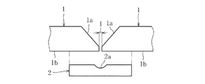
裏当金5は、溶接母材としての鋼板1と同じ材質の鋼板とされ、その板厚が鋼板1の板厚の略1/2〜1/3とされている。また、その長さは、鋼板1、1の溶接長さと同じとされ、その幅Wは、開先部即ち、対向する端面1a、1aの最大幅Lの略1.5倍程度とされている。図2に示すように鋼板1、1の裏側面1b、1bと対向する裏当金5の表側の面5aの中央には溶接裏波ビード幅Zよりも幅広の空間部としての溝5bが鋼板1、1の溶接方向(以下「長手方向」という)に沿って設けられている。
The
溝5bは、幅wが溶接裏波ビード幅Zの1.5倍以上(w≧1.5Z)とされ、深さYが開先幅lと略同じとされ、底面5cが平坦面とされている。尚、溝5bの底面5cと両側面とのなす隅部Rは、当該溝5bを加工する際に生ずるものであり、図示のように隅Rでもよく、或いは直角をなしてもよい。
また、溝5bの底面5cの中央に長手方向に沿ってマーキングライン5d(マーキング)が設けられている。このマーキングライン5dは、当該裏当金5の溝5bを例えば、押し出し成形により形成する場合は山形の凸条または凹条としてもよく、フライス盤により形成する場合には加工時にマーキングしてもよい。
The
A marking
以下に裏当金を用いた突合わせ片面溶接について説明する。
図1及び図2に示すように鋼板1、1の裏側面1b、1bに裏当金5の面5aを当接させ、溝5bの中央のマーキングライン5dを開先幅lの中央に位置するように配置し、不図示の治具により支持する。これにより、開先幅lの中央に裏当金5の溝5bの中央を簡単且つ正確に位置合わせすることができる。尚、この場合、裏当金5の長手方向に沿う一側の外縁部の両端、或いは長手方向に沿って適宜の箇所を対応する一側の鋼板1の裏側面1bにスポット溶接して仮止めしてもよい。そして、この状態において鋼板1、1の開先幅lの下方且つその両側に夫々幅2lをなし深さYをなす閉空間部Sが画成される。
Hereinafter, butt one-side welding using a backing metal will be described.
As shown in FIGS. 1 and 2, the
次いで、図2に示すように鋼板1、1の対向する開先部1a、1a及び開先幅lの部位を例えば、TIG溶接により溶接する。この溶接時に鋼板1、1の開先部1a、1a、及び裏当金5の溝5bの底部5cの中央部が溶融して溶着される。鋼板1、1の開先部1a、1aは、その表面から略開先幅l程度の厚みの部分1a'、1a'が溶接材3と共に溶融する(以下「溶融部1a'」という)。また、裏当金5の溝5bの底面5cは、略開先幅l程度の深さ部分5c'が溶接材3と共に溶融して溶着される(以下「溶融部5c'」という)。
Next, as shown in FIG. 2, the facing groove portions 1 a, 1 a and the groove width l of the
これにより、鋼板1、1の開先幅dの裏側に溶接裏波ビード3aが形成されてこれらの鋼板1、1が溶接される。また、裏当金5のマーキングライン5dにより鋼板1、1の開先幅lの中央に当該裏当金5の溝5bの中央部を容易に合致させることができるためにこれらの鋼板1、1の溶接不良を防止することが可能となる。
ところで、裏当金5の溝5bの幅wが裏波ビード幅Zの1.5倍以上とされていることで当該裏波ビード幅Zの両側に夫々略幅0.25Zの隙間(空間部)が形成された状態で溶接され、鋼板1の内側に張り出す溶接裏波ビード3aの付け根部3bから溝5bの左右両側の開口端までの間に空間部Saが残存することとなる。そして、この空間部Saが溶接時における断熱空間、及び裏当金5の変形可能空間として作用する。
Thereby, the
By the way, since the width w of the
即ち、開先部1a、1aの溶融時に発生した溶接熱は、空間部Saにより遮断されて裏当金5の溝5bの外側への伝達が抑えられ、これにより、裏当金5の急冷、溶接裏波ビード3aの収縮による付け根部3bからの亀裂(ビード割れ)の発生が有効に防止される。また、裏当金5の板厚が溶接母材である鋼板1の板厚の1/2〜1/3と薄いことで、当該裏当金5の剛性が低く、溶接裏波ビード3aの収縮時には図2に2点鎖線で示すように変形して残留応力の発生が大幅に低減される。
That is, the welding heat generated when the groove portions 1a and 1a are melted is blocked by the space portion Sa and is prevented from being transmitted to the outside of the
更に、鋼板1、1の溶融部1a'、1a'、及び裏当金5の溶融部5c'に至る溶接裏波ビード3aは、裏当金5の溝5bに向かって凸の曲面をなしていることから、付け根部3b即ち、鋼板1の裏側面1bと溶接裏波ビード3aの付け根部3bとのなす角θが鈍角となる。このため、前記付け根部3bにおける応力集中が少なくなり、負荷時に当該付け根部3bの部分の高応力の発生が有効に防止されて疲労強度が大幅に向上する。
Furthermore, the welded back
図4は、本発明の裏当金の他の実施形態を示し、裏当金6は、鋼板1、1の裏側面1b、1bと当接する表側の面6a中央に溶接方向(長手方向)に沿って一側方に開口させた形状の切欠6bを形成して空間部Sとしたものである。切欠6bの底面6cの中央には長手方向(溶接方向)に沿って断面三角形状をなす凸条のマーキングライン6dが設けられている。この裏当金6は、片持構造とされ、切欠6bの閉塞側の外側縁部6eを鋼板1の裏側面1bにスポット溶接等により仮止めする。
FIG. 4 shows another embodiment of the backing metal of the present invention, and the
このような形状の裏当金6は、例えば、円環状に形成して鋼管同士を突合わせ片面溶接する際に有効である。即ち、裏当金6の外側縁部6eを一側の鋼管の開口端の内側面にスポット溶接等で仮止めし、切欠6bの開口している側を他側の鋼管の開口端に挿入し、これらの鋼管の対向する開口端(開先部)を溶接し、溶接裏波ビードにより裏当金6を溶接する。
The
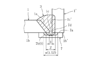
上述した実施例では、突合わせ片面溶接を例としたが、これに限るものではない。図5は、本発明の裏当金の他の実施形態を示し、隅肉溶接(角継手)に本発明の裏当金を採用したものである。裏当金7は、鋼板の開先部1aの下端1cと、鋼板1に対し略垂直に設けられた鋼板1'の開先部1c'が所定の開先幅(ルートギャップ)lを存して突き合うように配設されるレ形の開先形状を有した鋼板1、1'の裏側面1b及び端面1b'に表側の面7aが当接する。表側の面7aの中央に溶接裏波ビード幅Zよりも幅広(w≧1.5Z)の空間部Sとしての溝7bが鋼板1、1'の長手方向(溶接方向)に沿って形成され、溝7bの中央には長手方向(溶接方向)に沿って断面三角形状をなす凸条のマーキングライン7dが設けられている。この裏当金7は、該裏当金7の外側面を鋼板1、1'の端面1b、1b'に溶接等により仮止めする。
In the above-described embodiment, the butt one-side welding is taken as an example, but the present invention is not limited to this. FIG. 5 shows another embodiment of the backing metal of the present invention, in which the backing metal of the present invention is adopted for fillet welding (square joint). In the
本発明の実施形態では、開先形状がV形及びレ形のものを例としたが、これに限定されるものではない。例えば、他の開先形状(I形、U形、J形等)を適用した場合でも、本実施形態と同様の効果を奏することは勿論である。 In the embodiment of the present invention, the shape of the groove is V-shaped and L-shaped, but the present invention is not limited to this. For example, even when other groove shapes (I shape, U shape, J shape, etc.) are applied, it is a matter of course that the same effects as in the present embodiment can be obtained.
1、1' 鋼板(溶接母材)
1a 開先部
d 開先幅
3 溶接材
3a 溶接裏波ビード
3b 溶接裏波ビードの付け根部
5、7 裏当金
5b 溝(空間部)
5c 底面
5d、7d マーキングライン
S、Sa 空間部
6 裏当金
6b 切欠(空間部)
1, 1 'steel plate (welded base metal)
1a groove part
Claims (5)
前記裏当金の前記溶接母材側に、前記溶接母材の裏側に生成される裏波ビード幅より大きい空間部を設けたことを特徴とする溶接用裏当金の構造。 It is a structure of a welding backing metal used in a welding method in which the groove portions of the plate-like welding preforms to be welded are butted together and a backing metal that contacts the welding preform is disposed,
A structure of a welding backing metal, wherein a space larger than a width of a back bead generated on the back side of the welding base material is provided on the welding base material side of the backing metal.
Priority Applications (1)
| Application Number | Priority Date | Filing Date | Title |
|---|---|---|---|
| JP2005102268A JP2006281245A (en) | 2005-03-31 | 2005-03-31 | Structure of backing metal for welding |
Applications Claiming Priority (1)
| Application Number | Priority Date | Filing Date | Title |
|---|---|---|---|
| JP2005102268A JP2006281245A (en) | 2005-03-31 | 2005-03-31 | Structure of backing metal for welding |
Publications (1)
| Publication Number | Publication Date |
|---|---|
| JP2006281245A true JP2006281245A (en) | 2006-10-19 |
Family
ID=37403682
Family Applications (1)
| Application Number | Title | Priority Date | Filing Date |
|---|---|---|---|
| JP2005102268A Pending JP2006281245A (en) | 2005-03-31 | 2005-03-31 | Structure of backing metal for welding |
Country Status (1)
| Country | Link |
|---|---|
| JP (1) | JP2006281245A (en) |
Cited By (5)
| Publication number | Priority date | Publication date | Assignee | Title |
|---|---|---|---|---|
| JP2010120056A (en) * | 2008-11-20 | 2010-06-03 | Kobe Steel Ltd | Spot friction stir welding method of dissimilar metals |
| JP2012001153A (en) * | 2010-06-18 | 2012-01-05 | Shiroki Corp | Vehicle door frame and manufacturing method of the same |
| JP2017194088A (en) * | 2016-04-18 | 2017-10-26 | Kyb株式会社 | Pressure resistant apparatus and fluid pressure cylinder |
| WO2019164488A1 (en) * | 2018-02-22 | 2019-08-29 | Siemens Aktiengesellschaft | Welding tool and methodology for forming welding joints free of notch-induced cracking |
| JP2021030235A (en) * | 2019-08-14 | 2021-03-01 | 日本製鉄株式会社 | Welded structure |
Citations (1)
| Publication number | Priority date | Publication date | Assignee | Title |
|---|---|---|---|---|
| JPH03180275A (en) * | 1989-12-08 | 1991-08-06 | Sato Tekko Kk | One-side welding procedure |
-
2005
- 2005-03-31 JP JP2005102268A patent/JP2006281245A/en active Pending
Patent Citations (1)
| Publication number | Priority date | Publication date | Assignee | Title |
|---|---|---|---|---|
| JPH03180275A (en) * | 1989-12-08 | 1991-08-06 | Sato Tekko Kk | One-side welding procedure |
Cited By (6)
| Publication number | Priority date | Publication date | Assignee | Title |
|---|---|---|---|---|
| JP2010120056A (en) * | 2008-11-20 | 2010-06-03 | Kobe Steel Ltd | Spot friction stir welding method of dissimilar metals |
| JP2012001153A (en) * | 2010-06-18 | 2012-01-05 | Shiroki Corp | Vehicle door frame and manufacturing method of the same |
| JP2017194088A (en) * | 2016-04-18 | 2017-10-26 | Kyb株式会社 | Pressure resistant apparatus and fluid pressure cylinder |
| WO2019164488A1 (en) * | 2018-02-22 | 2019-08-29 | Siemens Aktiengesellschaft | Welding tool and methodology for forming welding joints free of notch-induced cracking |
| JP2021030235A (en) * | 2019-08-14 | 2021-03-01 | 日本製鉄株式会社 | Welded structure |
| JP7421061B2 (en) | 2019-08-14 | 2024-01-24 | 日本製鉄株式会社 | welded structures |
Similar Documents
| Publication | Publication Date | Title |
|---|---|---|
| JP5496152B2 (en) | Combined welding method of laser welding and arc welding of T type joint | |
| JP6354941B2 (en) | Method for suppressing groove shrinkage in automatic TIG back wave welding | |
| JPS58119481A (en) | Laser beam melting welding method | |
| CN112296494B (en) | Welding flux copper gasket method submerged-arc welding method for jointed boards with different thicknesses | |
| JP2004306084A (en) | Composite welding method of laser welding and arc welding | |
| JP2008043974A (en) | Longitudinal seam welded joint of uoe steel pipe | |
| JP2006281245A (en) | Structure of backing metal for welding | |
| JP6089323B2 (en) | Laser welding method for differential thickness materials | |
| JP2007268551A (en) | Multi-electrode one side submerged arc welding method | |
| WO2016163055A1 (en) | Fillet welding method for zinc plated steel | |
| US3688080A (en) | Welding | |
| JP5949539B2 (en) | Electrogas arc welding method | |
| JPH08243754A (en) | Inner face welding method of clad steel tube | |
| JP2006281246A (en) | Groove structure of fillet welding | |
| JP2002018583A (en) | Method of laser beam welding | |
| JP4202107B2 (en) | Welded joint structure | |
| JP5509798B2 (en) | Joining method | |
| JP6756253B2 (en) | Joining method | |
| JP7341937B2 (en) | Electroslag welding method | |
| JPH07266068A (en) | Method for laser beam welding aluminum or aluminum alloy member | |
| JP7434931B2 (en) | Lip forming method and welding method | |
| JP4128022B2 (en) | Groove butt welding method using insert member and insert member used therefor | |
| KR101091427B1 (en) | Method for fixing steel sheet in laser welding | |
| JP2001252781A (en) | Method of connection for clad steel | |
| KR102046957B1 (en) | High Efficient Welded Joint Having Excellent Brittle Crack Propagation Stopping Performance and Method for Manufacturing the Same |
Legal Events
| Date | Code | Title | Description |
|---|---|---|---|
| RD04 | Notification of resignation of power of attorney |
Effective date: 20060928 Free format text: JAPANESE INTERMEDIATE CODE: A7424 |
|
| A621 | Written request for application examination |
Free format text: JAPANESE INTERMEDIATE CODE: A621 Effective date: 20071226 |
|
| A977 | Report on retrieval |
Effective date: 20100312 Free format text: JAPANESE INTERMEDIATE CODE: A971007 |
|
| A131 | Notification of reasons for refusal |
Effective date: 20100317 Free format text: JAPANESE INTERMEDIATE CODE: A131 |
|
| A02 | Decision of refusal |
Free format text: JAPANESE INTERMEDIATE CODE: A02 Effective date: 20100721 |